

013749en
Operating Instruction Booklet
- Translation of the original instruction -
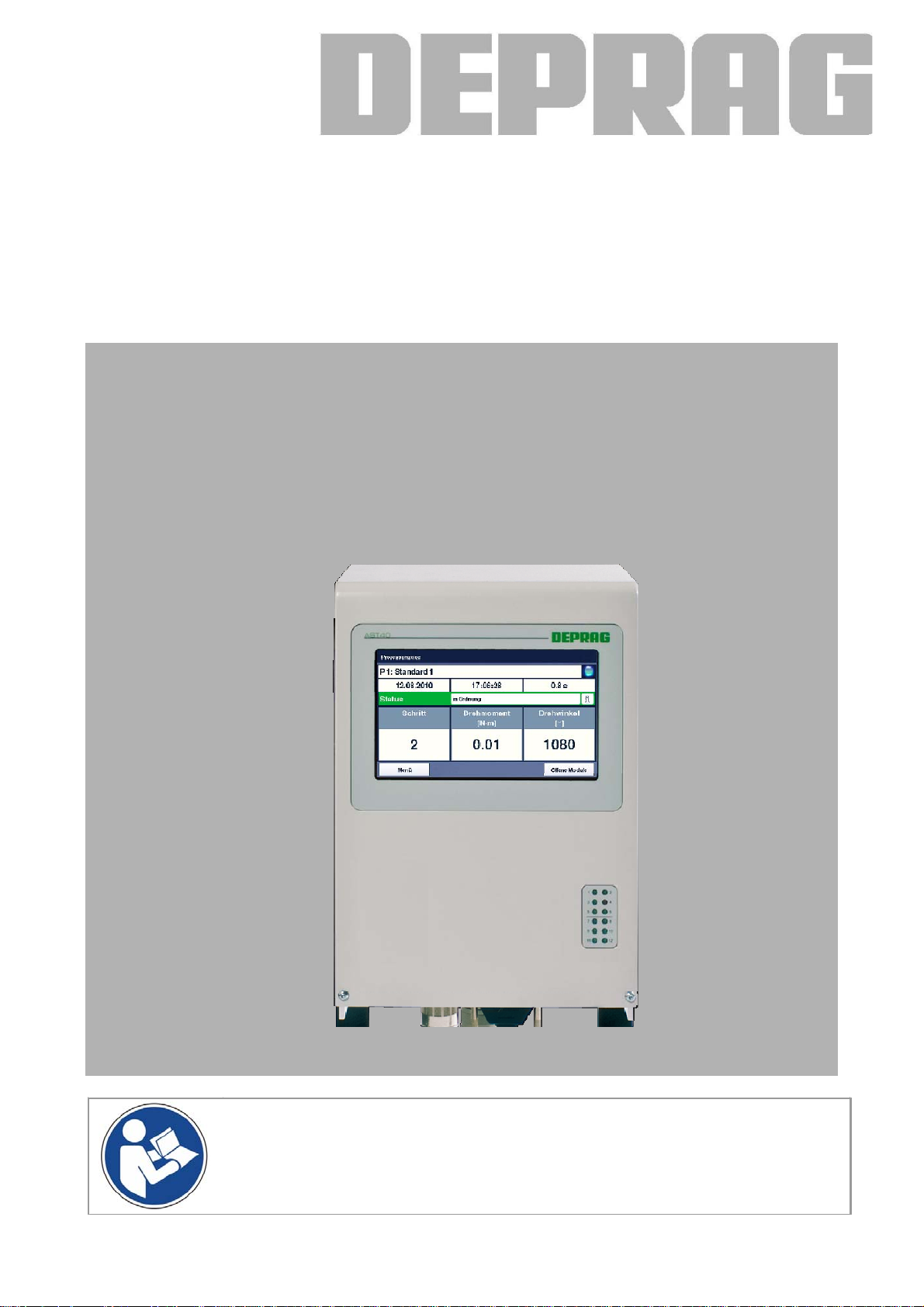
Sequence controller
AST40-1 385588 A
NOTICE ALL DOCUMENTATIONS !
Before beginning work this operating instru ction booklet and the enclosed
safety instructions (no. 01 6000, pink-colored boo klet) have to be read through
carefully. Always follow the instructions during operation. Give this operating instruction booklet and the ap propriate safety instructions to the operator.

Table of contents
1 DEFINITION OF SIGNAL WORDS AND SYMBOLS............................................................... 10
2 SAFETY INSTRUCTIONS........................................................................................................ 11
3 INTENDED USE .......................................................................................................................11
4 SCOPE OF DELIVERY............................................................................................................. 12
5 BRIEF DESCRIPTION.............................................................................................................. 12
6 HARDWARE DESCRIPTION................................................................................................... 13
6.1 AST40 Views ......................................................................................................................... 13
6.1.1 Front view........................................................................................................................ 13
6.1.2 Connection side .............................................................................................................. 13
6.2 Interface description............................................................................................................... 14
6.2.1 MINIMAT–EC-Servo Screwdriver ................................................................................... 14
6.2.2 Power Supply .................................................................................................................. 14
6.2.3 Ethernet........................................................................................................................... 14
6.2.4 USB................................................................................................................................. 14
6.2.5 Emergency Stop.............................................................................................................. 14
6.2.6 Printer (optional).............................................................................................................. 14
6.2.7 I/O interfaces................................................................................................................... 15
6.2.7.1 Voltage supply for I/O interfaces .................................................................................. 15
6.2.7.2 Interface SPS 1 ............................................................................................................ 15
6.2.7.3 Interface SPS 2 ............................................................................................................ 16
6.2.7.4 Interface 3 .................................................................................................................... 16
6.2.8 Fieldbus interface (optional)............................................................................................ 17
6.2.8.1 Profibus ........................................................................................................................ 17
6.2.8.2 Profinet......................................................................................................................... 17
6.2.8.3 EtherNet/IP................................................................................................................... 17
6.2.8.4 EtherCAT ..................................................................................................................... 17
7 START-UP................................................................................................................................ 18
7.1 Dimension sheet .................................................................................................................... 18
7.2 Assembly ............................................................................................................................... 19
7.3 Method of operation of the sequence controller AST40......................................................... 21
7.4 Instructions on programming the sequence controller ........................................................... 21
7.5 Connection to a higher level controller................................................................................... 21
7.6 Connection on a master controller via the Fieldbus (optional)............................................... 22
7.6.1 Profibus DP / Profinet...................................................................................................... 22
7.6.1.1 General Information ..................................................................................................... 22
7.6.1.2 Hardware configuration ................................................................................................ 22
7.6.1.3 Software ....................................................................................................................... 23
7.6.2 EtherNet/IP...................................................................................................................... 35
7.6.2.1 General Information ..................................................................................................... 35
7.6.2.2 Bus configuration ......................................................................................................... 35
7.6.2.3 Software - Import.......................................................................................................... 39
7.6.2.4 Software - description of data types............................................................................. 49
7.6.2.5 Ethercat........................................................................................................................ 56
8 USERS...................................................................................................................................... 57
9 OPERATION USING THE INTEGRATED TOUCH DISPLAY ................................................. 58
9.1 Control elements.................................................................................................................... 58
9.1.1 Buttons ............................................................................................................................ 58
9.1.2 Selecting between two options........................................................................................ 58
9.1.3 Selecting between several options.................................................................................. 59
9.1.4 Text and numerical input................................................................................................. 59
9.2 Description of the menu structure .......................................................................................... 60
9.2.1 Overview ......................................................................................................................... 60
2

9.2.2 Open modules................................................................................................................. 60
9.2.3 Registration ..................................................................................................................... 61
9.2.4 Process Data Menu Area ................................................................................................ 62
9.2.4.1 Process display ............................................................................................................ 62
9.2.4.2 Statistics....................................................................................................................... 63
9.2.4.3 Graphic......................................................................................................................... 64
9.2.5 System Menu Area.......................................................................................................... 65
9.2.5.1 System data ................................................................................................................. 65
9.2.5.2 System setup ............................................................................................................... 65
9.2.5.3 User Administration...................................................................................................... 70
9.2.5.4 Tool data ...................................................................................................................... 71
9.2.5.5 Screwdriver settings..................................................................................................... 72
9.2.5.6 Maintenance................................................................................................................. 72
9.2.6 Menu Area – Screwdriving Sequence............................................................................. 73
9.2.6.1 Screwdriving Sequence ............................................................................................... 73
9.2.7 Menu Area - Diagnosis.................................................................................................... 75
9.2.7.1 Tool status.................................................................................................................... 75
9.2.7.2 Tool test ....................................................................................................................... 76
9.2.7.3 I/O interface.................................................................................................................. 76
9.2.7.4 Fieldbus (optional)........................................................................................................ 80
9.2.7.5 System Image .............................................................................................................. 84
10 OPERATIONS USING THE WEB-BASED USER INTERFACE............................................ 86
10.1 Requirements....................................................................................................................... 86
10.1.1 Hardware....................................................................................................................... 86
10.1.2 Software ........................................................................................................................ 86
10.1.3 Connecting to the AST40 sequence controller.............................................................. 86
10.2 Preparing to use the web interface ...................................................................................... 86
10.2.1.1 Setting up the AST40 sequence controller................................................................. 86
10.2.1.2 Setting the browsers/operating systems .................................................................... 86
10.3 Description of the menus ..................................................................................................... 87
10.3.1 Start............................................................................................................................... 87
10.3.2 The menu structure ....................................................................................................... 89
10.3.3 System Menu Area........................................................................................................ 90
10.3.3.1 System data ............................................................................................................... 90
10.3.3.2 System settings.......................................................................................................... 90
10.3.3.3 Screwdriver data ........................................................................................................ 96
10.3.3.4 Screwdriver settings................................................................................................... 96
10.3.3.5 Tool status.................................................................................................................. 97
10.3.3.6 Maintenance............................................................................................................... 97
10.3.3.7 Log in ......................................................................................................................... 98
10.3.4 Menu Area – Screwdriving sequence ........................................................................... 98
10.3.4.1 Program Menu ........................................................................................................... 98
10.3.4.2 Create / Load Backup .............................................................................................. 101
10.3.5 Process Data Menu Area ............................................................................................ 102
10.3.5.1 Final values .............................................................................................................. 102
10.3.5.2 Statistics................................................................................................................... 102
10.3.5.3 Graphic..................................................................................................................... 103
10.3.6 Menu Area Extras ....................................................................................................... 104
10.3.6.1 Manuals.................................................................................................................... 104
10.3.6.2 Additional programs ................................................................................................. 104
10.3.6.3 Fieldbus.................................................................................................................... 105
10.3.6.4 Updates.................................................................................................................... 105
10.3.6.5 Unlocking ................................................................................................................. 106
10.3.6.6 System Image (only visible for logged in users)....................................................... 107
11 SETTINGS............................................................................................................................ 109
11.1 Description of the adjustable parameter ............................................................................ 109
11.1.1 Controller..................................................................................................................... 109
3

11.1.1.1 System Setting Parameters ..................................................................................... 109
11.1.1.2 Fieldbus system parameters (optional) .................................................................... 110
11.1.2 MINIMAT–EC-Servo Screwdriver ............................................................................... 111
11.2 Default values .................................................................................................................... 111
11.2.1 Controller..................................................................................................................... 111
11.2.1.1 Standard values for system settings ........................................................................ 111
11.2.1.2 Standard values for user data .................................................................................. 111
11.2.1.3 Standard values for fieldbus systems (optional) ...................................................... 112
11.2.2 MINIMAT–EC-Servo Screwdriver ............................................................................... 112
12 SCREWDRIVING STRATEGIES AND COMMANDS .......................................................... 113
12.1 Screwdriving Strategy ........................................................................................................ 113
12.1.1 Tighten / loosen to Torque .......................................................................................... 113
12.1.2 Extended screwdriving to torque................................................................................. 114
12.1.3 Screwdriving - tighten / loosen to angle ...................................................................... 115
12.1.4 Fasten / Loosen to external Stop-Signal ..................................................................... 117
12.1.5 Find ............................................................................................................................. 118
12.1.6 Friction Value Package (optional) ............................................................................... 119
12.1.6.1 Friction Value Measurement .................................................................................... 119
12.1.6.2 Screwdriving with a Differential Torque.................................................................... 120
12.1.6.3 Screw assemblies depending on friction.................................................................. 122
12.2 Commands......................................................................................................................... 125
12.2.1 Waiting for input .......................................................................................................... 125
12.2.2 Setting the output ........................................................................................................ 125
12.2.3 Resetting the output .................................................................................................... 125
12.2.4 Display values ............................................................................................................. 125
12.2.5 Save values................................................................................................................. 125
12.2.6 Statistics...................................................................................................................... 125
12.2.7 Waiting time ................................................................................................................ 125
12.2.8 Printing ........................................................................................................................ 126
12.2.9 Hold position ............................................................................................................... 126
13 DOCUMENTATION.............................................................................................................. 127
13.1 Final values........................................................................................................................ 127
13.2 Curve display ..................................................................................................................... 129
13.3 Statistic .............................................................................................................................. 130
13.4 Print output......................................................................................................................... 130
14 MAINTENANCE AND SERVICING...................................................................................... 133
14.1 General .............................................................................................................................. 133
14.2 Updating the software ........................................................................................................ 134
14.2.1 Main controller and display ......................................................................................... 134
14.2.2 Power Unit................................................................................................................... 134
14.2.3 Screwdriver Logic........................................................................................................ 134
14.3 Calibrating the touch display.............................................................................................. 135
15 ERROR DISPLAY AND TROUBLESHOOTING.................................................................. 136
15.1 System error ...................................................................................................................... 136
15.1.1 MINIMAT–EC-Servo Screwdriver ............................................................................... 136
15.1.2 Power unit ................................................................................................................... 136
15.1.3 Main controller............................................................................................................. 138
15.1.4 Communication ........................................................................................................... 138
15.1.5 I/O interface................................................................................................................. 138
15.2 Error in the Screwdriving Sequence................................................................................... 140
16 HELP WITH FAULTS........................................................................................................... 141
17 ACCESSORIES.................................................................................................................... 142
17.1 Power cord......................................................................................................................... 142
17.2 Emergency Stop Connector............................................................................................... 142
17.3 AST40 – PC Connection Cable.......................................................................................... 142
17.4 Fieldbus modules............................................................................................................... 142
4

17.4.1 Profibus ....................................................................................................................... 142
17.4.2 Profinet........................................................................................................................ 142
17.4.3 EtherCAT .................................................................................................................... 142
17.4.4 EtherNet/IP.................................................................................................................. 142
17.5 Printer Interface ................................................................................................................. 142
17.6 Stand.................................................................................................................................. 143
17.7 Touch-Pen ......................................................................................................................... 143
17.8 Optional software packages............................................................................................... 143
17.8.1 Friction value software package.................................................................................. 143
17.8.2 DataLogger ................................................................................................................. 144
17.8.3 GRAPH10 – curve overlapping ................................................................................... 145
17.8.4 TC30-PC Statistics...................................................................................................... 146
18 GLOSSARY.......................................................................................................................... 147
19 DECOMMISSIONING AND STORAGE................................................................................ 150
20 TECHNICAL DATA .............................................................................................................. 151
21 EC DECLARATION OF INCORPORATION ........................................................................ 152
22 SERVICE LOCATIONS AND AUTHORIZED PARTNERS.................................................. 153
5

List of figures
Figure 1: Front view of AST40 ..................................................................................................... 13
Figure 2: AST40 connection side................................................................................................. 13
Figure 3: Dimension sheet ........................................................................................................... 18
Figure 4: Hardware configuration of Profibus DP......................................................................... 22
Figure 5: Hardware configuration of Profinet ............................................................................... 23
Figure 6: Directory of the modules............................................................................................... 24
Figure 7: Creating Ethernet / IP - new module............................................................................. 36
Figure 8: Creating Ethernet / IP – select module ......................................................................... 37
Figure 9: Creating Ethernet / IP – confirm settings ...................................................................... 37
Figure 10: Import AST40.L5X – “Add-On-Instruction”.................................................................. 39
Figure 11: Import AST40.L5X – Confirm Import........................................................................... 40
Figure 12: Import AST40.L5X – “Final Name”.............................................................................. 40
Figure 13: Import AST40.L5X – Menu tree .................................................................................. 41
Figure 14: Import AST40_Cntrl.L5X – „Data Types“, „User-Defined“ and „Import Data Type“ .... 41
Figure 15: Import AST40_Cntrl.L5X – Confirm Import ................................................................. 41
Figure 16: Import AST40_Cntrl.L5X – Final Name ...................................................................... 42
Figure 17: Import AST40_Cntrl.L5X – Menu tree......................................................................... 42
Figure 18: Import Controller-Tags.csv – “Tags and Logic Comments” ........................................ 43
Figure 19: Import Controller-Tags.csv – “Import” ......................................................................... 43
Figure 20: Import Controller-Tags.csv – Error display ................................................................. 44
Figure 21: Import Controller-Tags.csv – Display controller tags .................................................. 44
Figure 22: Import AST40_Control.L5X – “Import Routine”........................................................... 45
Figure 23: Import AST40_Control.L5X – Confirm “Import”........................................................... 45
Figure 24: Import AST40_Control.L5X – Change „Final Name“ and „Description“ ...................... 46
Figure 25: Import AST40_Control.L5X – Menu tree..................................................................... 46
Figure 26: Import AST40_Control.L5X – Description of the module............................................ 47
Figure 27: Import AST40_Control.L5X – Add-On instruction call................................................. 48
Figure 28: Selecting between two options ................................................................................... 58
Figure 29: Selecting between several options ............................................................................. 59
Figure 30: Numerical block for numerical input............................................................................ 59
Figure 31: Keyboard for text input................................................................................................ 59
Figure 32: Main menu .................................................................................................................. 60
Figure 33: Open modules ............................................................................................................ 60
Figure 34: User log in................................................................................................................... 61
Figure 35: Process Data Menu Area............................................................................................ 62
Figure 36: Process display, Alternative 1..................................................................................... 62
Figure 37: Process display, Alternative 2..................................................................................... 63
Figure 38: Statistics ..................................................................................................................... 63
Figure 39: Graphic ....................................................................................................................... 64
Figure 40: System Menu Area ..................................................................................................... 65
Figure 41: System data................................................................................................................ 65
Figure 42: System setup – Language .......................................................................................... 66
Figure 43: System setup – Network............................................................................................. 66
Figure 44: System setup – Date / Time ....................................................................................... 67
Figure 45: System setup – General, Page 1................................................................................ 67
Figure 46: System setup – General, Page 2................................................................................ 68
Figure 47: System setup – Fieldbus, example without fieldbus ................................................... 68
Figure 48: System setup – Fieldbus, EtherCAT example ............................................................ 68
Figure 49: System setup – Fieldbus, EtherNet/IP example ......................................................... 69
Figure 50: System setup – Fieldbus, Profibus example............................................................... 69
Figure 51: System setup – Fieldbus, ProfiNet example ............................................................... 69
Figure 52: System setup – Process display selection.................................................................. 70
Figure 53: System setup – Setting standard values..................................................................... 70
Figure 54: System setup – Users................................................................................................. 71
Figure 55: Change user data ....................................................................................................... 71
6

Figure 56: Screwdriver Data, Page 1........................................................................................... 72
Figure 57: Screwdriver settings ................................................................................................... 72
Figure 58: Adjustment of the touch display.................................................................................. 73
Figure 59: Menu Area – Screwdriving Sequence......................................................................... 73
Figure 60: Creating a Default Program ........................................................................................ 74
Figure 61: Changing the Screwdriving Sequence........................................................................ 74
Figure 62: Menu Area - Diagnosis ............................................................................................... 75
Figure 63: Tool status – Page 1.................................................................................................. 75
Figure 64: Tool status – Page 2.................................................................................................. 76
Figure 65: Tooltest ....................................................................................................................... 76
Figure 66: Diagnosis I/O-Port, Inputs (Page 1)............................................................................ 77
Figure 67: Diagnosis I/O-Port, Program choice (Page 2)............................................................. 78
Figure 68: Diagnosis I/O-Port, Outputs (Page 3) ......................................................................... 78
Figure 69: Diagnosis I/O-Port, I/O interface (Page 4) .................................................................. 79
Figure 70: Diagnosis I/O-Port, Status (Page 5)............................................................................ 80
Figure 71: Diagnosis Fieldbus, Communication Flags (Page 1).................................................. 81
Figure 72: Diagnosis Fieldbus, Inputs (Page 2)........................................................................... 81
Figure 73: Diagnosis Fieldbus, Program Selection (Page 3) ....................................................... 82
Figure 74: Diagnosis Fieldbus, Outputs (Page 4) ........................................................................ 82
Figure 75: Diagnosis Fieldbus, Universal Inputs and Outputs (Page 5) ...................................... 83
Figure 76: System Image............................................................................................................. 84
Figure 77: The home page........................................................................................................... 87
Figure 78: Start page ................................................................................................................... 88
Figure 79: Web interface menu structure..................................................................................... 89
Figure 80: System data................................................................................................................ 90
Figure 81: Submenu items - System setup.................................................................................. 90
Figure 82: System setup .............................................................................................................. 91
Figure 83: System setup – Fieldbus, example without fieldbus ................................................... 92
Figure 84: System setup – Fieldbus, EtherCAT example ............................................................ 92
Figure 85: System setup – Fieldbus, EtherNet/IP example ......................................................... 93
Figure 86: System settings – Fieldbus, Profibus example ........................................................... 93
Figure 87: System setup – Fieldbus, ProfiNet example ............................................................... 94
Figure 88: Date / Time ................................................................................................................. 94
Figure 89: User Administration..................................................................................................... 95
Figure 90: Screwdriver data......................................................................................................... 96
Figure 91: Screwdriver settings ................................................................................................... 97
Figure 92: Tool status .................................................................................................................. 97
Figure 93: Adjustment of the touch display.................................................................................. 98
Figure 94: Submenu item – Screwdriving Sequence................................................................... 98
Figure 95: Screwdriving sequence – empty program................................................................... 99
Figure 96: Screwdriving Sequence – complete program ........................................................... 100
Figure 97: Final Values .............................................................................................................. 102
Figure 98: Submenu item Statistics ........................................................................................... 102
Figure 99: Statistics ................................................................................................................... 103
Figure 100: Downloading graphic .............................................................................................. 103
Figure 101: Manuals .................................................................................................................. 104
Figure 102: Additional programs................................................................................................ 105
Figure 103: Fieldbus .................................................................................................................. 105
Figure 104: Update .................................................................................................................... 106
Figure 105: Unlock Extension .................................................................................................... 106
Figure 106: System Image......................................................................................................... 107
Figure 107: Screwdriving Application to torque.......................................................................... 113
Figure 108: Extended screwdriving to Torque ........................................................................... 114
Figure 109: Screwdriving to Angle ............................................................................................. 115
Figure 110: Loosening on Angle ................................................................................................ 116
Figure 111: Fasten / Loosen to external Stop-Signal................................................................. 117
Figure 112: Friction Value Measurement................................................................................... 119
Figure 113: Screwdriving on differential Torque ........................................................................ 120
7

Figure 114: Screw assemblies depending on friction................................................................. 122
Figure 115: DataLogger ............................................................................................................. 144
Figure 116: GRAPH10E............................................................................................................. 145
Figure 117: TC30-PC Statistics program ................................................................................... 146
8

List of tables
Table 1: Scope of delivery ........................................................................................................... 12
Table 2: Configuration Interface Emergency stop........................................................................ 14
Table 3: Configuration Interface Printer ....................................................................................... 14
Table 4: Configuration I/O interface SPS1................................................................................... 15
Table 5: Assignment of LEDs to pins at interface SPS1.............................................................. 15
Table 6: Configuration I/O interface SPS2................................................................................... 16
Table 7: Configuration I/O interface 3 .......................................................................................... 16
Table 8: Configuration Interface Profibus .................................................................................... 17
Table 9: Modules and UDT's for the control................................................................................. 23
Table 10: Transfer parameters (FB12)......................................................................................... 24
Table 11: Data structure of the control signals (UDT21).............................................................. 26
Table 12: Data structure of the status signals (UDT22)............................................................... 29
Table 13: Status Signal Error Codes............................................................................................ 30
Table 14: Data structure of the screwdriving data (UDT22)......................................................... 33
Table 15: Creating Ethernet / IP – conform settings .................................................................... 38
Table 16: Software - Import.......................................................................................................... 39
Table 17: Import AST40_Control.L5X – Add-On Instruction ........................................................ 48
Table 18: Data structure AST40_Cntrl......................................................................................... 49
Table 19: Data structure AST40_IN_Signals ............................................................................... 51
Table 20: Data structure AST40_IN_FinalValues ........................................................................ 54
Table 21: Data structure AST40_OUT_Signals ........................................................................... 55
Table 22: Rights of the various user types................................................................................... 57
Table 23: Diagnosis I/O-Port, Inputs (Page 1) ............................................................................. 77
Table 24: Diagnosis I/O-Port, Program choice (Page 2).............................................................. 78
Table 25: Diagnosis I/O-Port, Outputs (Page 3) .......................................................................... 79
Table 26: Diagnosis I/O-Port, I/O interface (Page 4) ................................................................... 79
Table 27: Fieldbus, Inputs Diagnosis (Page 2) ............................................................................ 81
Table 28: Diagnosis Fieldbus, Program Selection (Page 3) ........................................................ 82
Table 29: Diagnosis Fieldbus, Outputs (Page 4) ......................................................................... 83
Table 30: Diagnosis Fieldbus, Universal Inputs and Outputs (Page 5)........................................ 84
Table 31: Adjustable parameters ............................................................................................... 110
Table 32: Configurable Profibus parameters ............................................................................. 110
Table 33: Configurable Profinet parameters .............................................................................. 110
Table 34: Adjustable EtherNet/IP Parameters ........................................................................... 110
Table 35: Adjustable Parameters MINIMAT–EC-Servo Screwdriver ......................................... 111
Table 36: Default values ............................................................................................................ 111
Table 37: Standard values - User data ...................................................................................... 111
Table 38: Default values for Profibus......................................................................................... 112
Table 39: Default values for Profinet.......................................................................................... 112
Table 40: Standard values EtherNet/IP...................................................................................... 112
Table 41: MINIMAT–EC-Servo Screwdriver Standard Values................................................... 112
Table 42: Structure of the data set in the files 1-7.csv and actual.csv....................................... 127
Table 43: Structure of the data set in the file actual_extended.csv............................................ 128
Table 44: Commands Printout ................................................................................................... 131
Table 45: System error MINIMAT–EC-Servo screwdriver ......................................................... 136
Table 46: System error - power unit........................................................................................... 137
Table 47: System error - Master control unit.............................................................................. 138
Table 48: System error – Communication.................................................................................. 138
Table 49: System Error - I/O Interface ....................................................................................... 139
Table 50: Sequence errors ........................................................................................................ 140
Table 51: Error Rectification....................................................................................................... 141
Table 52: Technical Data ........................................................................................................... 151
9

y
1 Definition of signal words and symbols
The signal words and symbols used in the technical documentation (safety instructions,
operat ing in struction b ooklet, et c.) have the follow ing meani ng:
DANG ER
Indicates an immediate danger which causes serious injuries or even
death if not avoided.
WARNING
Indicates a threatening danger which can cause serious injuries or even
death if not avoided.
CAUT ION
Indicates a dange r or uns a fe pr oc ed ur e which can cause injuries to a per-
son or material damages if not avoided.
NOTICE
Indicates a potentially dangerous situation which can cause damage to
the product or its surroundings if not avoided.
IMPORTANT
Ind i cates ti ps an d o ther usef ul i nformat ion.
In each case t he symbol used does not replace t he safety text. The text must always be
read full
. In some cases other symbols will be us ed with the signal words.
10
2 Safety instructions
Reading the enclosed safety instruction booklet no. 016000 (pink-coloured booklet) is
essential for working with the equipment.
WARNING
Fires, electric shocks and other injuries, or damages to components can be
caused if the safety guidelines are ignored.
WARNING
Risk of fatal injury due to electrocution!
Disconnect the electric equipment from the power supply before starting
any work on the tool (e.g. installation, changing of accessories or machine
tools, removal of covers prior to longer downtimes, maintenance works,
etc.).
Switch off the mains switch and pull out the mains plug!
3 Intended use
The sequence controller AST40 is designed exclusively for fittings in industrial use. And
must only be operated with DEPRAG MINIMAT–EC-Servo screwdrivers of the series
311E... . The system is especially suitable for applications requiring the highest demand of
quality, flexibility and documentation.
Use beyond its intended use is considered unauthorized and therefore improper.
Furthermore, DEPRAG is not liable for damage resulting from the misuse of the
instrument; the user alone is liable.
The correct use of the instrument includes compliance with all operating, maintenance and
repair instructions.
IMPORTANT
Please contact your DEPRAG Representative, our international service
centers or contact DEPRAG SCHULZ GMBH u. CO. directly if you have
any questions.
Visit our website at www.deprag.com
.
11
 Loading...