


No.C48431 00604A
INSTRUCTION MANUAL
ENGINE-DRIVEN AC GENERATOR
DCA-600P
IMPORTANT: READ AND UNDERSTAND THIS MANUAL
CAREFULLY BEFORE USE OF THIS MACHINE.
KEEP THIS MANUAL FOR YOUR FUTURE REFERENCE.
2-8-5 Nihonbashi-horidomecho, Chuo-ku, Tokyo, 103-8566 Japan

CONTENTS
A
pp
g
g
p
y p
g
g
g
g
p
y p
g
g
g
g
g
p
g
g op
pping
g
g
SAFETY PRECAUTIONS FOR GENER
TORS .................................................................... 2
1. DCA series ........................................................................................................................ 8
1-1 General ................................................................................................................... 8
1-2 Machine structure ................................................................................................... 8
1-3 Machine a
earance and internal component devices ........................................... 8
1-4 Control switches and meters ................................................................................... 10
1-4-1 En
1-4-2 En
ine start/stop controls ....................................................................................... 10
ine indicators .................................................................................................... 12
1-4-3 Generator controls and indicators ........................................................................... 19
2. Trans
2-1 Safet
ortation, storage and installation ............................................................................ 20
recautions for transportation, storage and installation ............................... 20
2-2 Transportation ......................................................................................................... 21
2-3 Stora
2-3-1 Stora
2-3-2 Preparin
e ................................................................................................................... 21
e method ...................................................................................................... 21
for operation ........................................................................................... 22
2-4 Installation ............................................................................................................... 23
2-4-1 Installation ............................................................................................................... 23
2-4-2 Checkin
3. O
eration .......................................................................................................................... 29
3-1 Safet
3-2 Connectin
3-2-1 Precautions in connectin
after installation ....................................................................................... 26
recautions for operation ............................................................................. 29
the load ................................................................................................ 31
the load ......................................................................... 31
3-2-2 Non-liner and sensitive loads .................................................................................. 31
3-2-3 Selection of cables .................................................................................................. 32
3-2-4 connectin
3-3 Groundin
3-4 Before startin
3-4-1 Checku
the load ................................................................................................ 33
............................................................................................................... 34
......................................................................................................... 34
before start-up ......................................................................................... 34
3-4-2 Instruction for Fuel Device ...................................................................................... 36
3-5 Startin
3-6 Durin
3-7 Sto
3-7-1 Stoppin
3-7-2 Emer
.................................................................................................................... 37
eration ..................................................................................................... 38
.................................................................................................................. 38
method ..................................................................................................... 38
ency stop ...................................................................................................... 38
3-7-3 Protection device .................................................................................................... 38
4. Fuel, coolant and lubricants ..............................................................................................40
5. Periodic checkup and maintenance .................................................................................. 43
5-1 Safety precautions for periodic checkup and maintenance ..................................... 43
5-2 Periodic chechup ..................................................................................................... 44
5-2-1 Maintenance schedule ............................................................................................ 44
5-2-2 Checking/every 250 hours ...................................................................................... 45
5-2-3 Checking/every 500 hours ...................................................................................... 46
5-2-4 Checking/every 1000 hours .................................................................................... 51
5-2-5 Table of periodical maintenance and checking ....................................................... 52
6. Troubleshooting .................................................................................................................. 53
7. Principal data ...................................................................................................................... 54
7-1 Readings on gauges ...............................................................................................54
7-2 Setting of switches .................................................................................................. 54
7-3 Reference conditions .............................................................................................. 54
7-4 Limitations ............................................................................................................... 54
7-5 General specifications ............................................................................................. 55
7-6 Conversion list of SI units into UK/US units ............................................................ 56

FOREWORD
• We are very thankful for your special choice of our MACHINE in the market.
• Please read this manual carefully and understand for proper use this machine.
• Please keep this manual at your prescribed location where operator can always take this manual.
• If you have any question or problem on this operation, please contact your nearest Distributors.
• Pay special attention to statements preceded by the following word.
DANGER: indicates an imminently hazardous situation which, if not heeded, will result in
WARNING: indicates a potentially hazardous situation which, if not heeded, could result in
death or serious injury.
death or serious injury.
CAUTION: indicates a hazardous situation which, if not heeded, may result in minor or
moderate injury or damage to the machine.
[ NOTE ]: indicates useful information for the machine operations.
- 1 -

SAFETY PRECAUTIONS FOR GENERATORS
In order to ensure safe operation, the following symbols are used for explanation of the
machine operation.
The following symbols, found throughout this manual, alert you to potentially dangerous
conditions to the operator, service personnel, or the equipment.
WARNING: This symbol refers to a hazard or unsafe practice which can result in severe
personal injury or death.
CAUTION: This symbol refers to a hazard or unsafe practice which can result in personal
injury or product or property damage.
[ NOTE ]: This symbols show handling precautions for effective operation and many years
of satisfactory operation.
Some of the items shown by “
CAUTION” may also cause death or serious injury.
Be sure to observe all the items, as they are important for safe operation.
• If the machine is used by an outsider, you are requested to explain him correct handling and
advise him to read this instruction manual carefully.
• Do not modify the machine at your discretion, as it affects the safety, performance or the life of
the machine.
• If the machine is modified or it is used incorrectly against this manual or unauthorized parts are
used, the warranty of manufacturer will become invalid.
- 2 -
SAFETY LABEL
Safety labels are attached to the following positions of the machine.
• Keep these safety labels clean at all times.
• When safety labels are spoiled or lost, contact distributor or our office specifying the nameplate
No. shown below and ask for new ones.
Parts name Parts number
CAUTION : Instruction manual B9111 0220
DANGER : Electric shock B4510 0250
WARNING : Fire/explosion B9045 0100
CAUTION : Burn B9111 0240
CAUTION : Moving parts B9040 0050
CAUTION : Hot coolant B9041 0020
CAUTION : Engine fan B9040 0060
WARNING : Engine exhaust B9042 0020
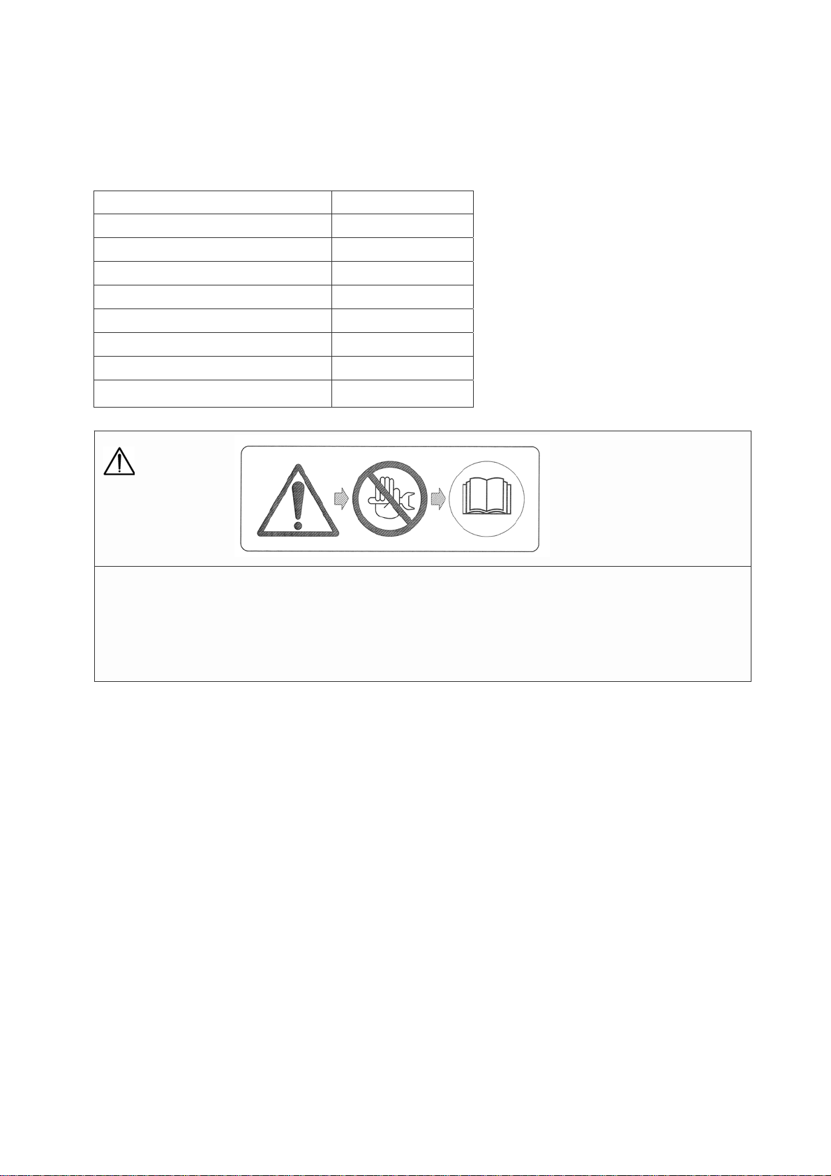
CAUTION:
Instruction manual
• Do not use machine before reading the instruction manual.
• Do access to machine in accordance with the instruction manual when machine is in fault.
• Do consult to authorized person for repair or maintenance to avoid incidents.
- 3 -

Do not touch the output terminals during operation to prevent decease due to electric shock.
DANGER: ELECTRIC SHOCK can kill.
• Never touch the output terminals during operation. If your hands or the machine are wet, it will result in
a death or serious injury.
• When a wiring work is required, be sure to turn OFF the circuit breaker and stop the machine.
• Keep the output terminal cover closed and the terminal bolts tightened while the machine is running.
• A low voltage is generated even when the machine is in low speed idle operation. Be sure to stop the
machine completely.
Do not touch the electrical parts in the machine during operation, as it may lead to death due to electric
shock.
• Always close the control panel and tighten the fixing bolts before operating the machine.
• Always close the side door and lock it before operating the machine.
• When opening the control panel for voltage selection, etc., turn OFF the circuit breaker and stop the
machine.
DANGER:
ELECTRIC SHOCK
by leak can kill.
Improper grounding may lead to death due to
electric shock.
• Be sure to execute the grounding of the machine
and the load according to the local rule.
CAUTION:
MOVING PARTS can
cause severe injury.
Rotary unit which runs at a high speed is located in
the machine. (Note that it is very dangerous if you
touch it.)
• Be sure to close the door and lock it during
operation.
• When the door needs to be opened during operation, do not get your hands and head in the
machine to prevent them from being caught in
the machine which may lead to injury.
• When making check or maintenance of the machine, be sure to stop the machine in advance.
- 4 -

Fuel and oil are flammable. Incorrect handling
results in danger of ignition or fire.
• When fuel needs to be supplied to the machine,
be sure to stop the engine. Refrain from smoking.
Keep the machine away from fire.
• Do not leave flammable objects (paper, wood
chips, etc.) and hazardous objects (oil, powder,
etc.) near the machine.
• Wipe off spilt fuel and oil.
WARNING: DIESEL
FUEL can cause fire
or explosion.
CAUTION:
HOT PARTS can burn
skin.
High temperature units are located in the machine.
(Note that these units are very dangerous if they are
used incorrectly.)
• Be sure to close the door and lock it during
operation.
• If the door needs to be opened during operation,
do not get your hands and head in the machine to
prevent unexpected burns.
• When making check or maintenance of the
machine, be sure to stop the machine.
• The bonnet is still hot even after the machine is
stopped. Be careful until the engine is completely
cooled.
CAUTION: ENGINE
EXHAUST can kill.
Insufficient ventilation may lead to death due to
lack of oxygen or poisoning by exhaust gases.
• Do not use the machine in a place of poor ventilation or in a place where exhaust gases stays.
• Do not use the machine indoors or in storehouse,
tunnel, ship hold, tank, etc. of poor ventilation.
• If it becomes necessary to use the machine in
the above places, the exhaust pipe should be
extended to a well ventilated place. In this case,
use a ventilator to ensure proper ventilation.
• Do not direct the exhaust outlet to nearby
pedestrians and houses.
CAUTION:
HOT COOLANT can
cause severe scalds.
If the radiator cap is opened while the water
temperature is high, steam or hot water will spout
out.
• During operation or immediately after stopping
the machine, do not open the radiator cap while
the water temperature is high.
• When cooling water needs to be checked or supplied, wait until the engine is cooled (50°C or less
as measured with the water temperature gauge).
CAUTION: Battery.
Battery generates flammable gases. Improper
handling may lead to explosion or serious injury.
• Battery should be charged in a well ventilated
location. Otherwise, flammable gases are accumulated which may be ignited and exploded.
• When connecting a booster cable, do not jumper
the terminals (+ and -). Otherwise, the flammable
gases generated from the battery may be ignited
and exploded by sparks.
• For maintenance of the machine, disconnect the
ground cable on the ground side.
The battery acid is dilute sulfuric acid. Improper
handling will cause unexpected burns.
• When the battery acid gets on your clothes or skin,
wash it out with a large volume of water immediately. If it gets in your eyes, wash with a large volume
of water immediately and consult your doctor.
In the worst case, it will put out your eyes.
• For checking or handling of the battery, be sure to
stop the engine and turn OFF the battery switch in
advance.
- 5 -
CAUTION: Operator.
Do not operate the machine if operator is tired too
much or drinks some alcohol or take some drugs.
• Otherwise, it may cause unexpected accidents or
injury.
During checking or maintenance, be sure to put on
suitable clothes and protectors.
• Do not put on baggy clothes, necklace, etc.,
because they are easily caught by projections
which may cause injuries.
CAUTION: Connection to house
Before connecting this machine to any building’s
electrical system, a licensed electrician must install
an isolation(transfer) switch.
• Serious injury or death may result without this
transfer switch.
wiring.
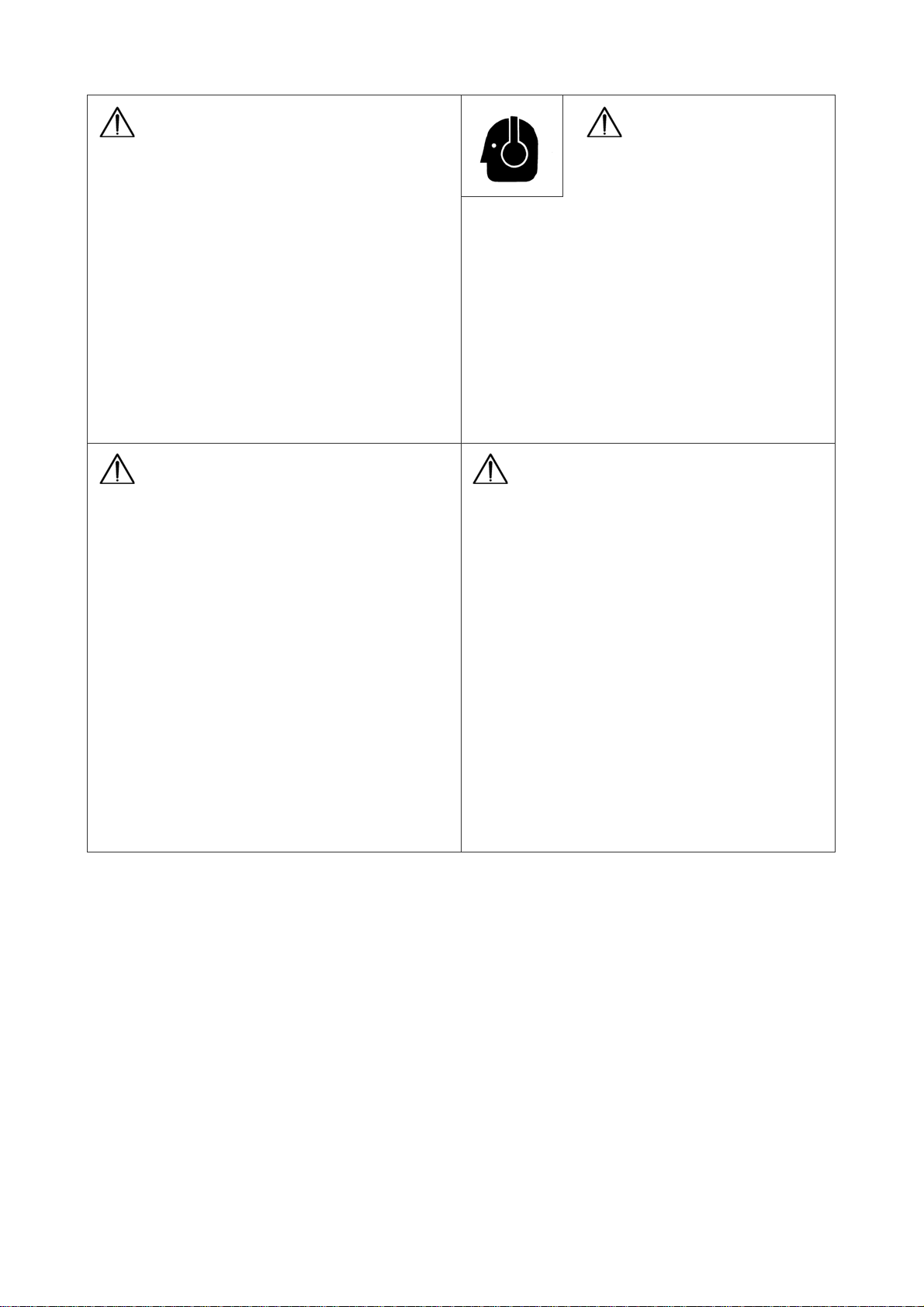
CAUTION:
Noise.
This machine generates large noise if the door is
open. Surrounding to large noise may cause hearing
trouble.
• Close and lock the door during operation.
• If opening the door is necessary during operation,
be sure to put on the ear protector.
CAUTION: Transportation.
Do not lift the machine except hanger of base
because it is not strong enough for lifting and
may cause a falling accident.
• When lifting the machine, use the hanger located
at the roof center.
• Keep out under the lifted machine.
Do not lift or do not transport the machine during
operation, as it may cause damage to the fan or
serious trouble.
• When loading the machine on the truck or the
like, fix the machine firmly by hanger on the
both side.
- 6 -

SAFETY LABEL
Model DCA-600P
Parts number
1 DANGER: Electric shock
2 WARNING: Fire/explosion
3 CAUTION: Burn
4 CAUTION: Moving parts
5 CAUTION: Instruction manual
6 CAUTION: Hot coolant
7 CAUTION: Engine fan
8 WARNING: Engine exhaust
This instruction manual
describes how to handle the
machine with a view to
promising safety run, maximum
efficiency and long durability.
Read the manual attentively
before starting the machine
operation for correct handling,
operation and appropriate
maintenance from the beginning.
The maintenance schedule
consists of a procedure of
keeping the machine in good
condition.
For the user, keep the manual
carefully for machine operation
and maintenance according to
the instructions. Observe all the
safety precautions including
ones stated in the manual.
Entrust the repair to trained
personnel of Denyo or its
distributor who are capable of
contacting us as required.
When consulting us, specify
the model and serial number
indicated on the nameplate.
For data not specified in the
manual, see “Principal data”.
The company reserves the right
to make changes without prior
notice.
- 7 -

SAFETY PRECAUTION:
• The user must carry out all safety precautions stated in the manual.
• If any statement in this book, especially with regard to safety, does not comply
with local legislation, the stricter of the two shall apply.
1. DCA SERIES
1-1 General
• DCA series generator is intended for generating power source where there is no power source.
• For further details, see “7 Principal data”.
1-2 Machine structure
• The generator which is directly driven by Perkins water-cooled diesel engine is mounted on
the common frame along with control equipment, radiator, battery(option), fuel tank(option)
and other auxiliary equipment. See Fig. 1.
1-3 Machine appearance and internal component devices
• There are the hanger at the base on its both sides. When lifting the machine, use the hanger.
Do not resort to winding rope because it is not strong enough. See Fig. 2.
• The engine cooling water refilling port and fuel refilling port(option) are located on the top
surface of the machine.
• The drain plugs for engine oil, cooling water and fuel(option) are located at the base side
under the machine. Tags of their respective names are attached there.
Fig. 1 Model DCA-600P
Parts number
1. AC generator
2. Diesel engine
3. Control box
4.
Fuel tank
5. Radiator
6.
Battery
7.
Muffler
8. Intercooler
(option)
(option)
(option)
- 8 -

Fig. 2 Model DCA-600P
Parts number
Parts number
1. Hanger 6. Radiator cooling water drain plug
2. Radiator cooling water refilling port 7. Engine exhaust port (without muffler)
3. Fuel tank refilling port (with fuel tank) 8. Engine exhaust port (with muffler)
4. Fuel drain plug (with fuel tank) 9. Fuel inlet (only without fuel tank)
5. Oil drain plug 10. Fuel outlet (only without fuel tank)
- 9 -

1-4 Control switches and meters
• The control panel is mounted on the bodywork with hinges and is fastened by screws.
Loosening the screws has access to repairing or replacing electrical parts in the control
box.
1-4-1 Engine start/stop controls
Fig. 3 Model DCA-600P
Parts number
Parts number
1. Frequency meter 8. Pilot lamp
2. Ac ammeter (U) 9. Engine indicator
3.
Ac ammeter (V) 10. Coolant level warning lamp
4. Ac ammeter (W) 11. Operation switch
5. Ac voltmeter 12. Start button
6. Voltage regulator
Speed regulator
13.
7. Circuit breaker (for main) 14. Emergency stop button
- 10 -

1. Operation switch
The switch is 2-position switch which can be operated with its specific key only.
RUNOFF/STOP
1) OFF/STOP
This switch should be set in this position unless the machine is in operation.
The key can be inserted or pulled out in this position.
OPERATION SWITCH
RUNOFF/STOP
2) RUN
This switch should be set in this position when the machine is in operation.
OPERATION SW ITCH
2. Start button
KEEP ON PU SHING
TO START ENGINE .
START BUTTON
3. Emergency stop button
BEFORE STARTING , CHECK
EMERGENCY STOP BUTTON I S RESET
RESET
EMERGENCY STOP BUTTON
4.Speed regulator
HIGH
SPEED REGULATOR
LOW
In this position, the preheating system is energized.
This button keep on pushing to start the engine.
The stop button is a push button to stop the engine in case of an emergency.
When the button is pressed, it must be unlocked by turning it anti-clockwise
before the engine can be re-started.
Turn the switch toward the “HIGH” side to increase the speed and toward the
“LOW” side to decrease it.
- 11 -

1-4-2 Engine indicators
5. Engine monitor
(1) Engine indicator
That indicates the numerical values of engine speed, engine oil pressure, run hours,
battery charging voltage, or engine coolant temperature.
Indicated Items Unit
engine speed min
-1
engine oil pressure ×100kPa
battery charging voltage V
engine coolant temperature ºC
1 - Engine Speed
• Revolutions per minute is indicated. 1500/1800 min
2 - Engine Oil Pressure
• 3.0 to 6.0 × 100 kPa should be indicated at normal engine operation.
• Higher value would be indicated in cold condition immediately after engine starts.
• Conduct a warning - up operation until it indicates normal value.
3 - Battery Charging Voltage
• That should indicate more than 26.0V at engine running.
4 - Engine Coolant Temperature
• That should indicate a temperature between 75 to 90°C at engine running.
[ NOTE ]: If that would indicate higher temperature, disconnect all loads, and wait until
the temperature comes down to normal value.
-1
is indicated at 50/60Hz.
- 12 -
(2) Fuel Level Indicator (Only with Fuel Tank)
That Indicates a fuel level in the fuel tank. All the lights are indicated green when the fuel
is full. The green lights stop indicating one by one as the fuel level decrease, finally the
red light will be indicated when it is only one green light is left. Replenish the tank when
there becomes only one lamp turned on. The table below shows the relation between
numbers of turn - on lamps and fuel level.
Numbers of lamps
turned-on
(3) Alarm and Memory at Abnormal Condition
When any abnormal condition occurs in engine oil pressure, battery charging voltage,
or engine coolant temperature, the indication will change as the following;
9
8
7
6
5
4
3
2
1
DCA-600P
Fuel level (L)
450 to full
405 to 450
345 to 405
295 to 345
245 to 295
195 to 245
165 to 195
120 to 165
0 to 120
1 - The Indicator shows its defect with blinking numbers.
2 - When the abnormal condition is corrected, the on - and - off indication will stop.
3 - If engine would stop urgently and automatically or stop manually with the abnormal
condition, the abnormal value will be memorized, and then indicated even after engine
is started again.
In this case, keep on pushing the button “RESET” for more than 5 seconds, and the
abnormal indication will be reset to normal.
- 13 -

(4) Warning Lamps
This monitor indicates the following failures, if any one of them occurs.
① High jacket water temperature (WATER TEMP)
This lamp goes on when the water temperature rises abnormally.
If the lamp goes on during operation, the emergency stop device
immediately operates to shut down the engine automatically.
② Low lubricating oil pressure (OIL PRESS)
If this lamp goes on during operation, the emergency stop device
immediately operates to shut down the engine automatically.
(5) Hour Meter
① When you turn the starter switch to “RUN” position, and push the selector button located
on the right side of the Hour Meter, you can see the numbers mentioned below;
• “ODO” Total running hour
• “TRIP A” Running hours “A” on a certain period
• “TRIP B” Running hours “B” on a certain period
② If you want to reset the Trip Meters, push the selector button for more than 1 second,
after selecting each meters.
- 14 -

(6) The hour meter has an internal battery
The engine monitor incorporates both a rechargeable internal battery as well as a
charging circuit.
While the generator is not in operation, the engine monitor will still indicate the hours
operated via its internal battery.
While the generator is in operation, the internal battery recharges.
When the generator remains unused for a long period of time, the battery will continue to
lose its charge. Once the charge is exhausted, the hour meter will not indicate hours, and
the battery will need to be recharged. From a completely exhausted state, recharging the
battery for 30 minutes will only result in a 30 minute charge to the battery.
However, if charged for 3 hours, the hour meter will indicate hours for more than 10 days
without another charge.
Please refer to the table below to see the relationship between battery time charging
versus length of indication by the hour meter.
6. Coolant level warning lamp
This lamp goes on when the coolant amount become
lower than the fixed amount.
If the lamp goes on during operation, the emergency stop device
Immediately operates to shut down the engine automatically.
7. Controller breaker
COOLANT LEVEL WARNING LAMP
This breaker protects engine hardware.
Before insert the key in the operation switch, switch this breaker to ON.
CONTROLLER
BREAKER
- 15 -

8. Switch and Lamp for Electronic Governor Controller (in the control box)
(1) Isochronous-Droop Change-over switch
The generating set can change the governor control between
”Isochronous Governor Control and Droop Governor Control”
by “Isochronous-Droop Change-over switch” where is equippped
with the control box.
The original position at factory shall be set in “Droop Governor
Control”. Operate the unit in condition of “Droop Control”
in common.
In case of starting with a heavy load, operate the unit in condition
of ” Droop Governor Control” because it is better for starting
efficiency than “Isochronous Governor Control “.
Explanation for the control
① “Isochronous Governor Control “----- Frequency is constant regardless of load.
When the generator is set in a frequency thet will be pointed in condition of NO-LOAD,
the governor controls the frequency constantly regardless of load.
② “Droop Governor Control “----- Frequency will be alternative depending on load.
” Droop Governor Control” means that frequency can be alternative depending on load.
When the rated frequency will be reduced at about 2.0 Hz against NO-LOAD.
Therefore, NO-LOAD frequency should be set at 52.0 to 52.5Hz.
(2) Frequency change – over switch
This is for switching the frequency from 50Hz to 60Hz or 60Hz to
50Hz.
SHUTDOWN LAMP ACTION AL ERT L AMP F AULT R ESE T
WARNING LAMP DIAGNOSTICS L AMP
FREQUENCY
CHANGE- OVE R S WITCH
50Hz ISOCHRONOUS
60Hz
DROOP
ISOCHRONOUS-DROOP
CHANGE-OVER SWITCH
ISOCHRONOUS-DROOP
CHANGE-OVER SWITCH
FREQUE NCY
CHANGE-OVER SWITCH
ISOCHRONOUS
DROOP
50Hz
60Hz
- 16 -

(3) Diagnostic Lamp
This lamp is sometimes called the check engine light.
The diagnostic lamp is used to warn the operator of the presence
of an active diagnostic code. The lamp may not be included in all
applications.
(4) Fault Reset
In case turn off the Diagnostic Lamp, push this button.
(5) Engine Monitoring
This engine monitoring system monitors the following parameters.
・ Engine oil pressure
・ Coolant temperature
・ Intake manifold air temperature
・ Engine speed
・ Boost pressure
・ Fuel temperature
The monitoring system has three levels of operation.
The levels are described below.
Warning Operation (lev el 1)
In the Warning condition, the ECM causes the warning lamp to
come ON. The warning lamp indicates that a fault has been
detected by the engine monitoring system. No further action by
the ECM or the engine occurs.
Action Alert Operation (level 2)
In the Action Alert condition, the ECM causes the action alert
lamp to come on. The Action Alert lamp indicates that a fault has
been detected by the engine monitoring system. This condition is
normally wired in order to cause a shutdown and the shutdown is
controlled by the control panel on the machine.
Shutdown Operation (level 3)
If the fault reaches the Shutdown condition, the ECM causes the
shutdown lamp to come on. Unless the engine is in a Critical
Override condition, the engine will shut down.
DIAGNOSTICS LAMP
FAULT RESET
WARNING LAMP
ACTION ALERT LAMP
SHUTDOWN LAMP
- 17 -

Settings for the Monito ring Sy stem
Parameter State Trip Point Delay Time
Low Engine Oil Pressure
Warn Operator On
Action Alert Always On
Engine Shutdown Always On
300 kPa
(43.5 psi)
250 kPa
(36.3 psi)
200 kPa
(29.0 psi)
60 seconds
2 seconds
2 seconds
High Engine Coolant Temperature
Warn Operator On 104°C (219°F) 60 seconds
Action Alert Always On 105°C(221°F) 10 seconds
Engine Shutdown Always On 108°C(226°F) 10 seconds
Engine Overspeed
Warn Operator On 2000 RPM 1 second
Action Alert Always On 2050 RPM 0 second
Engine Shutdown Always On 2140 RPM 0 second
High Intake Manifold Air Temperature
Warn Operator On 75°C (167°F) 60 seconds
Action Alert Always On 78°C (172°F) 10 seconds
High Fuel Supply Temperature
Warn Operator On 60°C (140°F) 60 seconds
Action Alert Always On 68°C (154°F) 60 seconds
High Boost Pressure
Warn Operator On
300 kPa
(43.5 psi)
60 seconds
Action Alert Always On Map 5 seconds
- 18 -

1-4-3 Generator controls and indicators
9. Frequency meter
This meter indicates the frequency of the outputted voltage. Make sure that it reads
50Hz or 60Hz when running.
10. Ammeter (U, V, W)
This meter indicates the current going to the connected load. It must not exceed the
rated current.
11. Voltmete r (Include voltmeter change-over switch)
The voltmeter indicates the outputted line voltage.
12. Three-phase circuit breaker
The circuit breaker is a safety device interrupting the mains when an overload or a
short circuit occurs at the load side connected to the receptacles. It also serves
as a main switch for supplying energy from the generator to the load connected to the
output receptacles.
Do not use this circuit breaker to turn on or off the load.
When tripped, the breaker must be reset manually by switching it to OFF and then to
ON after eliminating the cause of the trouble.
13. Voltage regulator knob
The output voltage is controlled by a regulator with rotating knob. Turning clockwise
increases the voltage and vice versa.
14. Pilot lamp
The lamp will be turned on if a dynamo generates electricity.
- 19 -

2. TRANSPORTATION, STORAGE AND INSTALLATION
2-1 Safety precautions for transportation, storage and installation
WARNING
• When lifting or transporting the machine, use only appropriate devices which comply with
the local safety codes and regulations.
• When lifting the machine, use the hanger of base.
• Do not resort to rope winding because it is not strong enough.
• Before lifting, close and fix covers and other moving parts and clear away the machine
interior and top.
• Do not slip under a lifted machine.
• The electrical connections shall comply with the local codes.
• Earth the machine properly.
• The engine exhaust gas is lethal and toxic. Do not operate in places where the aeration is
poor. Discharge the exhaust sufficiently by a ventilating system. Never direct the engine
exhaust towards passers-by.
• Do not operate the machine in an atmosphere containing toxic or combustible gas. Otherwise,
fire or explosion might occur in the machine. (Example: Near volatilizing paint solvent.)
• Fuel and oil are combustible and undiluted anti-freeze solution is inflammable. Do not
smoke while handling or refilling them. Do not get fire or heated objects near them. Do not
spill or leave fuel, oil, anti-freeze solution or cleansing agent in or around the machine.
If spilled, be sure to wipe off properly.
• If necessary, provide a spark arrestor to trap incendiary exhaust sparks.
CAUTION
• Install the machine on a well ventilated, horizontal, flat, dry and solid floor. If the floor is
not horizontal enough to keep the machine leveled, consult your sales distributor. When
installing the machine on a trailer, fasten the trailer and fix the wheels by stoppers.
• Do not remove or unduly modify safety devices, guards, covers or insulating materials from
the machine.
• When servicing batteries, always wear protecting clothing and glasses. The battery electrolyte is
a diluted sulphuric acid which can cause severe burns. Get it away from eye, skin and clothing.
• When charging batteries, an explosive gas forms above the cells and escapes through the
vents. Do not smoke near batteries just after having been charged. Never make or break
live circuits or battery terminals, because a spark usually occurs.
• Before checking the machine, stop the engine and wait for at least 10 minutes so that it will
cool down completely. If done while running or immediately after shutdown, you might get
burnt or injured.
- 20 -

2-2 Transportation
• When lifting or transporting the machine, use only appropriate devices which comply with
the local safety codes and regulations.
For dimensions and weight of the machine, refer to “7 Principal Data”.
See Fig 5 for the center of gravity. (without optional parts)
Fig. 5
Model L W H
DCA-600P 1970 mm 20 mm 700 mm
• When lifting the machine, use the hanger of base.
Never use the rope hanger because it is not strong enough to lift.
• Before lifting, close and fix the covers, and other moving parts and clear away the machine
interior and top.
• Do not slip under a lifted machine.
• Before transporting by truck or others, wind ropes on the machine to fasten it securely.
• Put covers so as to protect the machine from rain or moisture when transporting.
2-3 Storage
2-3-1 Storage method
1. Store the generator in a sufficiently ventilated, dry room which is free from frost, salt and dust.
Storage environment: Atmospheric temperature -15 to 55°C, humidity 95% or lower.
2. Run the engine once a week until warm.
- 21 -

3. If it is impossible to run the engine regularly, extra precautions must be taken.
1) Consult the instruction manual for the engine.
2) Remove the battery. Store it in the same environment as for the machine. Keep the
battery clean and coat its terminals lightly with petroleum jelly. Recharge the battery
regularly.
3) If the electrolyte has dropped to the specified level, refill it.
4) Clean the generator. Oil or fuel spillage is not allowed. Protect all electrical components
against penetration by moisture.
5) Enclose the generator, except the bottom, with a plastic bag.
2-3-2 Preparing for operation
Before operating again the generator kept unused for a long time, remove the plastic bag,
VCI paper from the openings and silica gel from inside and check the generator thoroughly.
Further maintain the following items.
1. Consult the instruction manual for the engine.
2. Measure the insulation resistance of the generator with a 500-V insulation resistance tester.
The resistance must exceed 1 MΩ.
In case of measuringwith an insulation resistance tester over 500VDC current, disconnect
all connectors from the AVR located in the control box before measuring.
3. Replace the fuel filter cartridge and fill the fuel tank.
Vent the fuel system.
4. Reinstall and connect the battery. If necessary, recharge it.
5. Check the fan belt condition and tension; adjust if required.
6. Check and, if required, refill cooling water and oil.
7. Submit the generator to a test run.
- 22 -

2-4 Installation
2-4-1 Installation
1. Install the generator on a well ventilated, horizontal, even and solid floor. If the floor is not horizontal
enough to keep the machine leveled, consult your sales distributor. When installing the machine on a
trailer, fasten the trailer and fix the wheels by stoppers. Avoid a site exposed to rain or high temperature.
The operating ambient conditions are atmospheric temperature of
-5 to 46°C, humidity of 85% or lower and altitude of 1000m or ower.
If the machine do not conform with the above conditions, consult your sales distributor.
2. Avoid a dusty site. If it is inevitable, provide protective devices.
3. Do not operate the machine in an atmosphere containing toxic or combustible gas. Otherwise
fire or explosion might occur in the machine. (Example: Near volatilizing paint solvent.)
4. Leave space for operation, inspection and maintenance; at least 1200 mm each on machine
front and rear and sides. See Fig. 6
Fig. 6
[ NOTE ]: If the machine is operated in a smaller space than that shown above, the room
temperature will rise. Please reduce the generator output in such condition. Therefore
proper power reduction is necessary.
If the space required above the machine is not uniform, make a decision so that:
• The radiator can be refilled with cooling water.
• The exhaust pipe can be introduced.
• The exhaust can smoothly be discharged.
- 23 -

5. Do not direct the exhaust towards passers-by or residences, etc.
6. Install an exhaust pipe of sufficient diameter to let the engine exhaust gas out directly.
7 . Check for sufficient ventilation and position the ventilator so that the exhaust from the machine
will not be re-circulated in the room even if the ventilation is proper.
8. Check that the inner earthing system is in compliance with the local regulations.
9. Also connect the load bodyworks to ground.
- 24 -

Model DCA-600P
Fig. 7
1. Oil level gauge 6. Alternator
2. Oil refilling port cap 7. Fuel pre filter
3. Oil drainr 8. Fuel filter
4. Expansion tank cooling water 9. Air cleaner
5. Fan belt
- 25 -

.
2-4-2 Checking after installation
(1) Check engine oil
(Read the instruction manual for the engine furnished separately.)
①
[ NOTE ]: Oil is consumed gradually during operation. When the ma-
Check the level of engine oil by the dipstick. Make sure the oil level
is always between H and L.
② When it is below the low limit, supply oil immediately.
③ At the same time, check condition of oil by the dipstick
chine is to be used continuously for a long time, be careful
with lack of oil.
(2) Check engine cooling water
(Read the instruction manual for the engine furnished separately.)
①
② Maintai the coolant level at the bottom of the filler pipe.
③.Clean the filler cap and check the condition of the cap gaskets.
Remove the filler cap from the expansion tank slowly to relieve
the pressure.
Renew the filler cap if the gaskets are damaged. Fit the filler cap.
[ NOTE ]: When closing the radiator cap after water level is checked or
water is supplied, turn the cap fully clockwise so that it can be
firmly tightened.
Otherwise, cooling water is evaporated which results in serious
damage to the engine.
(3) Check fan belt
(Read the instruction manual for the engine furnished separately.)
①
②
Check the belt for tension and elongation. Also, check it for damage.
Replace if necessary.
For adjustment or replacement of the belt, refer to the instruction
manual for the engine.
Press (about 6kg) the position shown by arrow mark (middle of belt) with
your thumb.
The bend should be within the range of 10 mm.
Parts number of fan belt:
Parts name
Parts number Parts number of manufacture
Fan Belt Y06020 15287 CH11186
Alternator Belt Y06020 15288 CH11037
(4) Check fuel level
①
②
Be sure to check the quantity of fuel prior to operation to
prevent lack of fuel during operation.
Loosen the drain plug of the fuel tank from time to time,
and remove sediment’s and water at the bottom of the tank.
- 26 -
CAUTION
B
attery
• The battery acid is dilute sulfuric acid. Improper handling will cause unexpected burns.
• When the battery acid gets on your clothes or skin, wash it out with a large volume of
water immediately. If it gets in your eyes, wash with a large volume of water immediately
and consult your doctor.
• In the worst case, it will put out your eyes.
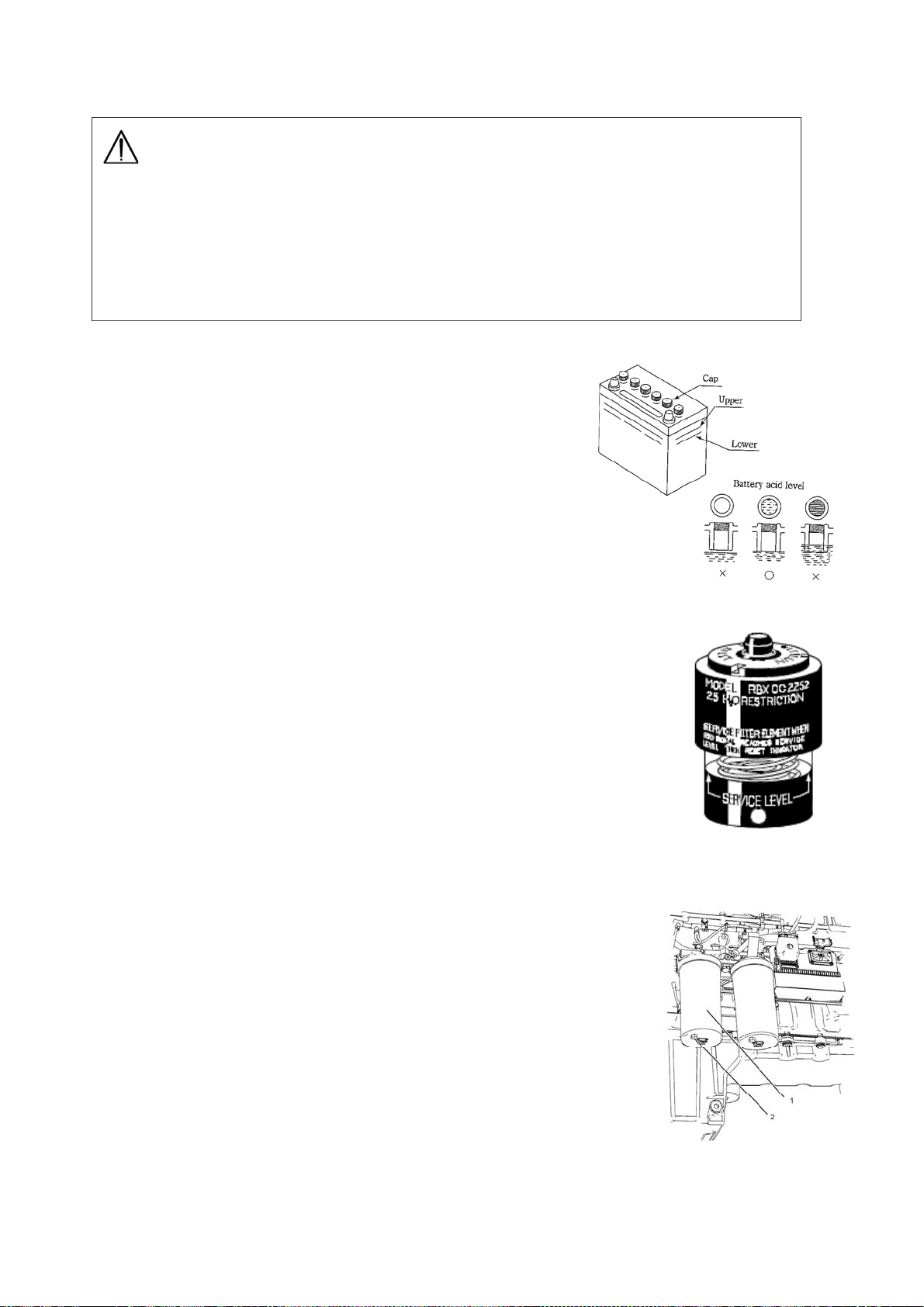
(5) Check battery acid level
Remove the battery acid plug(cap) and check the liquid
level (10-12 mm above the electrodes). Supply distilled
water if necessary.
(6) Check air cleaner service indicator
This engine may be equipped with a different service indicator.
This engine are equipped with a differential gauge for inlet air
pressure. The differential gauge for inlet air pressure displays
the difference in the pressure that is measured before the air
cleaner element and the pressure that is measured after the air
cleaner element. As the air cleaner element becomes dirty, the
pressure differential rises. If your engine is equipped with a different
type of service indicator, follow the OEM recommendations in order
to service the air cleaner service indicator.
The service indicator may be mounted on the air cleaner housing or
in a remote location.
Observe the service indicator. The air cleaner element should be
cleaned or the air cleaner element should be replaced when the
following condition occurs:
・ The red piston locks in the visible position.
(7) Drain water in fuel primary filter
1. Place a suitable container below the primary fuel filter assembly (1).
2. Remove the drain plug (2). Allow the fluid to drain into the container.
Check the O ring seal on the drain plug for damage. If necessary,
replace the O ring seal.
3. When clean fuel drains from the primary fuel filter install the drain
Plug. Tighten the drain plug to the following torque 1.2 N-m (11 lb in).
Dispose of the drained fluid correctly.
(8) Check for leak of water and oil
Check the machine for the trace of leak of oil or water.
If a leak is found, check the location of leak and stop it.
When the leak cannot be stopped, contact our service
factory.
- 27 -

(9) Check for loose parts
Check for loose bolts and nuts. Loose parts should be tightened firmly. Particularly, make
check on (the fitting of air cleaner, muffler, turbo-charger, etc.), disconnection of electric wiring,
short-circuit and loose terminals.
(10) Removal of foreign objects in machine
• Check that tools and cleaning cloth are not left in the machine. Remove if necessary.
• Check the surroundings of the muffler and engine for presence of dust and flammable
objects. Remove if necessary.
- 28 -

3. OPERATION
3-1 Safety precautions for operation
DANGER
• When the machine is running, never touch output terminals, internal wiring or other electrical
parts.
• Do not use the machine in a humid place. An excessive humidity is very dangerous.
Never touch the machine if the machine or your body is wet.
• The electrical connections shall comply with the local regulations.
• Use cables which are not damaged. Make sure that all electrical connections are securely
fastened. Damaged cables or loose connections might cause electric shocks.
WARNING
• The engine exhaust gas is lethal and toxic. Do not operate in places where the aeration is poor.
Discharge the exhaust by a ventilation facility. Do not direct the engine exhaust towards passersby, residences, etc.
• Do not operate the machine in an atmosphere containing toxic or combustible gas. Otherwise,
fire or explosion might occur in the machine. (Example: Near volatilizing paint solvent.)
• Do not refill fuel or oil while the machine is running but after stopping the engine.
• Fuel and oil are combustible and undiluted anti-freeze solution is inflammable. Do not smoke
while handling or refilling them. Do not get fire or heated object near them.
• Do not spill or leave fuel, oil, anti-freeze solution or cleansing agent in or around the machine.
• Never remove the cover of the output terminals during operation. Before connecting or
disconnecting the cables, switch off the load and machine circuit breakers, stop the machine
and make sure that the machine cannot be started inadvertently.
• Eelectric shock by leak can kill.
Improper grounding may lead to death due to electric shock.
*Be sure to execute the grounding of the machine and the load according to the local rule.
- 29 -

CAUTION
• Avoid overloading the generator.
The generator is provided with circuit breakers for overload protection. When a circuit breaker
has tripped, reduce the concerned load before re-starting.
• Do not connect the output voltage from the machine to facilities wired to the commercial power
supply.
• Before connecting a load, turn off a corresponding circuit breaker and make sure that the
frequency, voltage and power factor of the load to connect match the generator ratings.
• Before checking the machine, stop the engine and wait for at least 10 minutes so that it will cool
down completely. If done while running or immediately after shutdown, you might get burnt or
injured.
• Do not operate the machine beyond the range given in the main specification table.
• In room or environment where the sound pressure level reaches or exceeds 90 dB (A), use ear
protectors.
• During the operation, keep all panels closed.
• Periodically check that:
1. All guards are in place and securely fastened.
2. All hoses and/or pipes are in good condition, not bent and not rubbing.
3. There are no leaks of fuel, oil, cooling water, etc.
4. All fasteners are tight.
5. All electrical leads are secure and in good order.
6. The electrical cables are not damaged.
[ NOTES ]: • Do not remove any of, or tamper with, the sound-damping material.
• Whenever an abnormal condition arises, e.g., excessive vibration, noise, odour,
etc., switch the circuit breakers to OFF and stop the engine. Correct the faulty
condition before re-starting.
- 30 -

3-2 Connecting the load
3-2-1 Precautions in connecting the load
• The switchgear, switching equipment, load and generator in the plant must be connected in
compliance with local codes of low voltage power installation (1000 or less).
• Before starting or before connecting a new load, make sure that the generator is earthed.
Use the earthing rod or, if effective, use an existing earthing installation. Any protective devices
against electric shock and leakage would be useless if earthing is poor.
• Avoid overloading the generator. The generator is provided with circuit breakers for overload
protection when a breaker has tripped, reduce the concerned load before restarting.
• Never connect the generator output voltage to an installation which is also connected to a
commercial power supply.
• Before connecting a load, turn off the corresponding circuit breaker, and check whether
frequency, voltage and power factor comply with the ratings of the generator.
• Distribution board
If the outlets provided on the machine are insufficient, provide an auxiliary switchgear and
connect it with the output terminals. The distribution board must comply with the local rule of
power installation.
• Be sure to provide a load ON/OFF switch between the power outlets and load. Do not use the
generator circuit breaker to turn on/off the load.
• Before connecting the load, stop the engine and turn off the generator circuit breaker.
• The load connecting cable must not get in contact with other output terminals on the terminal
board.
3-2-2 Non-linear and sensitive loads
Non-linear loads draw currents with high contents in harmonics causing distortion in the wave form
of the voltage generated by the synchronous generator.
In general, non-linear type loads generate a high frequency current which adversely affects the
performance of inverters used to feed power voltage to variable speed motors or loads such as
thyristor/rectifier controlled UPS.
Loads most sensitive to voltage distortion include incandescent lamps, discharge lamps,
computers, X-ray equipment, audio amplifiers and elevators.
Consult your sales distributors for measures against the adverse influence of non-linear and
sensitive loads.
- 31 -

3-2-3 Selection of cables
Use cables having sufficient size in consideration of the allowable current of the cables and the
distance between the machine and the load.
If the load current exceeds the allowable current of cables, the cable may be damaged by overheat.
Also, if the cables are too small in size for the length, the input voltage of the load drops which
lowers the working efficiency or causes failure in operation.
Select the length and size of cable so that the voltage drop “e” obtained by the following equation
is within 5% of the rated voltage.
* Equation to obtain 3-phase, 3-wire system voltage drop “e” from the length and size of cable
and operating current is as follows.
L = Length of one wire (m)
I = Generator rated current (A)
S = Cable thickness (mm
e = Voltage drop (V)
2
)
- 32 -

3-2-4 Connecting the load
1. Check whether frequency, voltage and current conform with the ratings of the generator.
2. Install for the load cable, without excessive length, and lay it out in a safe way without forming
coils.
1. Cable clamp
2. Cable outlet
3. Ground terminal(for bonnet)
4. Output terminal U
5. Output terminal V
6. Output terminal W
7. Output terminal O
Fig. 8
3. When connecting output terminals (See Fig. 8.)
• Remove the protection cover of output terminals.
• Loosen the cable clamp and push the wire ends of the load cable through the clamp and cable
outlet.
• Connect the wires to the proper terminals: U/V/W, and if
required O, for 3-phase load
O/U, O/V and O/W for single-phase load
• Tighten the bolts securely.
• Reinstall the protecting cover in front of the output terminal board.
• Tighten the clamp to fasten the cable.
- 33 -

3-3 Grounding
Execute the grounding certainly to prevent the electric shock by leak.
1. Case grounding of the machine
Use the grounding wire which sectional area conforms to the local rule.
Provide the grounding resistance which conforms to the local rule.
2. Case grounding of the load
Execute the grounding for the load similarly.
Provide the grounding rod to satisfy the grounding resistance which conforms to the local rule.
3. Precaution in grounding
1) Select a shady and highly moist place, and burry the grounding rod in such way
that its top end is completely hidden in the ground.
2) If burying the grounding rod on the place that many pedestrians walk on, clamp
the lead wire to prevent catching on it.
3) If the lead wire is not long enough for the connection, connect it as directed below:
* Connect the lead wire and the extension wire by soldering or sleeve coupling
securely and apply insulating tape to the connection.
* Do not burry the connection in the ground.
4) Avoid the places within 2m of lighting conductor grounding location for burying of grounding rod.
5) Do not use a telephone set grounding conductor.
3-4 Before starting
The generators are factory-adjusted to operate at 50/60 Hz, i.e. 1500/1800 min-1.
3-4-1 Checkup before start-up
1. Checking the oil level
• Check the engine oil level or contamination by the dipstick. The oil level must be near to,
but not exceed, the high mark on the dipstick. If required, refill or change the oil.
• If necessary, pour oil up to the specified level through the oil refilling port provided on the
engine.
• For oil change, loosen the oil drain plug from the generator base to drain and, thereafter, pour
oil the same as refilling. Dispose of the discharged oil in compliance with the local regulations.
• After supplying oil, run for several minutes, then stop the engine and make sure that the oil level is
between the high and low marks.
• For the oil volume, see the lubricant volume in the specification table.
- 34 -

2. Checking the cooling water in engine radiator
• Remove the filler cap and check that the water level is bottom of the filler pipe. Refill if short.
• Use soft water as engine cooling water. Use anti-freeze solution where the atmospheric tem- perature is
low.
Mixing volume of anti-freeze solution = total cooling water volume×mixing anti-freeze solution
concentration. For the total cooling water volume, see the engine specification table.
For anti-freeze solution concentration at the temperature, see “Fuel coolant and lubricants”.
• For making up water, remove the radiator cap. Thereafter, securely install the cap so as to be airtight.
3. Checking the fan belt tension
• Check the fan belt tension and elongation. By a thumb, depress (approx. 6kg) the middle point
of the belt. The deflection must be 10-15 mm. At the same time, check whether the belt is
scratched or not. If abnormal, adjust or replace it. For belt checkup, adjustment and
replacement.
4. Checking the fuel (The fuel tank of this machine is the option.)
• Check the fuel level. Refill if required.
• If the fuel remainder is small, dew might be formed in the tank and mix with the fuel.
To avoid such inconvenience, it is recommended to refill the tank fully after the day’s work.
• Loosen the drain plug from the fuel tank to drain water and sediment from the tank.
Dispose of the sediments, etc. in compliance with the local codes.
5. Checking the battery (The battery of this machine is the option.)
• Check whether the electrolyte level is within the specified range or not. If short, add distilled
water.
• If plates are exposed to air for a long time, the battery life would shorten. Keep them dipped.
• Do not pour battery electrolyte beyond the UPPER LEVEL.
• After refilling, securely tighten the caps.
• Give attention to the connection of battery plus (+) and minus (-) terminals. Reverse wiring of
the terminals will cause damage to generator instruments.
6. Checking the wiring
• Check whether the wiring is securely tightened or rubbed.
If abnormal, repair or replace.
7. Checking the piping
• Check whether the piping is securely tightened or leaky. Make sure that the hoses are not
worn. If abnormal, repair or replace.
- 35 -

8. Checking the bolts and nuts
• Check whether bolts and nuts are securely tightened or not especially for the air cleaner,
muffler mounting section. If loose, retighten them.
3-4-2 Instruction for Fuel Device
(1) Setting Procedure for Separate Tank
Where fuel source is a separate tank placed outside the machine, disconnect the tank
connection plug and change the connection as shown in the Fig.9.
(2) Caution on Setting
① For the piping, use oil-resistant hose of 9.6 mm or more internal diameter. Under Cold environ- ment,
use the hose of lager diameter.
② Install the separate fuel tank as near the machine as possible.
③ Set the suction end in the separate tank at the position of 15 to 20 mm upper than the bottom
level (as shown in Section-A of the Fig.9), so that water or sediment may not come into the
suction.
④ While feeding the fuel into the separate tank, do not allow water or dust to come in.
Fig. 9
- 36 -

3-5 Starting
1. Insert the key in the operation switch. Turn the key to RUN keep on pushing start button to
start engine.
• Do not engage the starter for more than 10 seconds at a time; if the engine does not fire, wait
2 minutes before restarting.
• Consult your sales distributor if starting is in extremely cold conditions.
• If the engine would not start after several tries, check whether the fuel level is too low, air is
not bled sufficiently or the battery is discharged.
2. Make sure that the engine warning lamps is extinguished. If alight, stop the engine, check the
item for which it is alight and eliminate the cause.
• Check the engine indicator for normal readings.
3. Check whether the frequency meter read as shown below or not.
Frequency
50Hz operation 50.0Hz 51.3~51.8Hz
60Hz operation 60.0Hz 61.5~62.1Hz
Isochronous Droop
• Check the voltmeter indication and, when the voltage is deviated from the rated voltage,
please contact your nearest Distributor.
4. Check the voltmeter indication and, if required, adjust with the voltage regulator knob.
Turning clockwise increases the voltage and vice versa.
5. When three-phase voltage is supplied, switch the three-phase circuit breaker to ON.
6. Switch on the load and check the frequency meter and voltmeter once more.
Adjust voltage if necessary.
Frequency (3-phase) Voltage
50Hz operation 50 Hz 190~220V or 380~440V
60Hz operation 60 Hz 190~240V or 380~480V
- 37 -

3-6 During operation
1. Periodically check that
• Indications of the engine monitor, indicator lamps and meters are normal.
• Oil, fuel and cooling water do not spill.
• The engine exhaust color is normal. There are no unusual sound and vibration.
• A light load is not applied for a long time. Otherwise, the engine output might drop.
• Each single-phase load is connected in balance whenever it is used.
• The engine oil level checked daily is normal. Refill if necessary.
[ NOTE ]: If the circuit breakers are tripped during operation, switch off the load and stop the
engine. Check and, if necessary, decrease the load.
3-7 Stopping
3-7-1 Stopping method
1. Switch the load circuit breakers to OFF.
2. Switch the generator circuit breaker to OFF.
3. Let the engine run for about 5 minutes to cool down.
4. Stop the engine by turning the key to STOP.
5. If the machine is not used any longer, withdraw and keep the key.
3-7-2 Emergency stop
To stop the engine in an emergency, press the emergency stop button.
3-7-3 Protection device
Protection devices and emergency stop devices are provided for protection of the machine against
trouble during operation.
When the warning lamp lights, stop the engine immediately. Check and remove the cause of
trouble.
- 38 -

Table of protection device
warning
oil pressure failure
(OIL PRESS.)
high jacket water
temperature
(WATER TEMP.)
Battery charging
failure
overcurrent of
generator
fuel level failure
(FUEL LEVEL)
(Optional apparatus)
air filter blinding
(AIR FILTER)
over speed of engine
(OVER SPEED)
coolant level failure
action
turn OFF
the circuit
breaker
– –
– stop
– –
–
– – ※
– –
– – –
– stop – set point: 2140 min
– stop
※
Abnormal value and unit will be indicated lighting on and off.
Stop the
engine
stop
indicate by
warning
lamp
※
※
function
set point: 300kPa
set point: 200kPa
set point: 103°C
set point: 108°C
set point: 26.0V
– –
When overcurrent flows, the
device acts.
When fuel supply is necessary
because of fuel shortage, the
device acts.
When replace or cleaning of
air filter is necessary because
of blinding of filter, the device
acts.
-1
When coolant supply is
necessary because of coolant
shortage, the device acts.
- 39 -
B
4. FUEL, COOLANT AND LU
RICANTS
Engine oil selection:
For engine oil, use API grade : CG-4, ACEA grade : E5 or EMA grade : DHD-1.
The brands/types of oil described PERKINS’s instruction manual can be used regardless
of specified API, ACEA or EMA grade above.
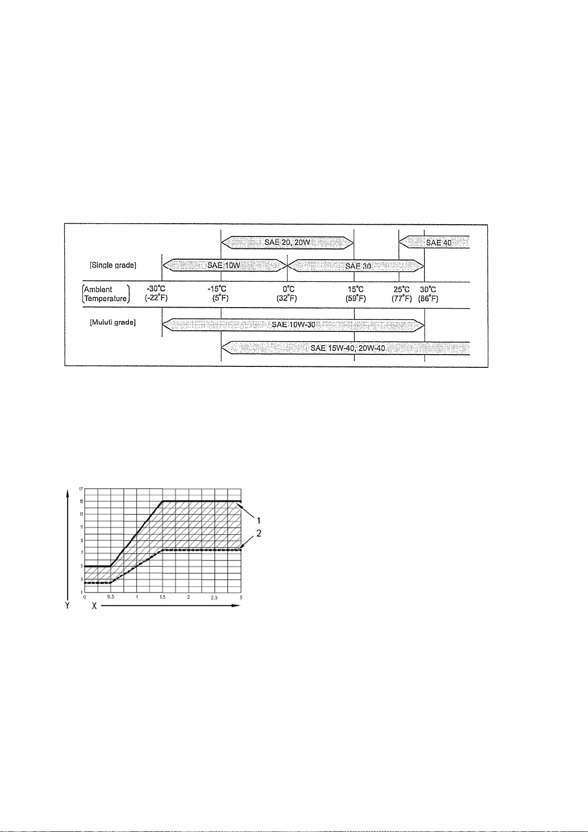
Oil viscosity:
Engine oil viscosity largely affect engine startability, performance, oil consumption, speed of
wearing and occurrence of seizure, etc. Using lubricants whose viscosity selected according to
the atmospheric temperature is important.
Total Base Number (TBN) and Fuel Sulfur Levels for Direct Injection (DI) Diesel Engines
The Total Base Number (TBN) for an oil depends on the fuel sulfur level. For direct injection
engines that use distillate fuel, the minimum TBN of the new oil must be 10 times the fuel sulfur
level. The TBN is defined by “ASTM D2896”. The minimum TBN of the oil is 5 regardless of fuel
sulfur level. Illustration 19 demonstrates the TBN.
(Y) TBN by “ASTM D2896”
(X) Percentage of fuel sulfur by weight
(1) TBN of new oil
(2) Change the oil when the TBN deteriorates to
50 percent of the original TBN.
Use the following guidelines for fuel sulfur levels that exceed 1.5 percent:
• Choose an oil with the highest TBN that meets one of these classifications:
API CG-4, ACEA E5 and EMA DHD-1.
• Reduce the oil change interval. Base the oil change interval
on the oil analysis. Ensure that the oil analysis includes the condition of the oil and a wear
metal analysis.
Excessive piston deposits can be produced by an oil with a high TBN. These deposits can
lead to a loss of control of the oil consumption and to the polishing of the cylinder bore.
- 40 -

[ NOTE ]: Operating Direct Injection (DI) diesel engines with fuel sulphur levels over
0.5 percent will require shortened oil change intervals in order to help maintain
adequate wear protection.
Percentage of Sulfur in the fuel
Lower than 0.5 Normal
0.5 to 1.0 0.75 of normal
Greater than 1.0 0.50 of normal
Fuel selection:
The following specific advantages are required for the diesel fuel.
1) Must be free from minute dust particles.
2) Must have adequate viscosity.
3) Must have high cetane value.
4) Must have high fluidity at low temperature.
5) Must have low sulfur content.
6) Must have little residual carbon.
Applicable Standard
Recommendation
Oil change interval
JIS (JAPANESE INDUSTRIAL STANDARD)
ASTM D975
BS2869-1997
BS EN590 1997
In fuel other than the specified one is used, engine function will be lowered.
NO. 2
No. 1-D or 2-D
Class A-2
- 41 -

The modern, high pressure fuel injection system used on the 2800 Series engines
a high level of fuel cleanliness to ensure correct operation and reliability.
The fuel must conform to all aspects of the ASTM D975 specification, but in
particular to the requirement for number 2-D to have less than 0.05% water and
sediment. The fuel should also be free biological growth. For long term storage of
fuel, the recommendations given in ASTM D975 must be followed where
appropriate.
The use of fuels which do not conform to the above standards can cause: difficully
with starting, poor combustion, deposits in the fuel injectors or combusiton
chamber, reduced service life of the fuel system and filters, reduced engine life
and could affect the warranty.
Cooling water :
Always refer to the chart to determine the correct cooling water to antifreeze solution
mixing ratio.
- 42 -

5. PERIODIC CHECKUP AND MAINTENANCE
5-1 Safety precautions for periodic checkup and maintenance
WARNING
• Before checking or maintaining the machine, stop the engine, wait for it to cool down and
remove all loads from the machine. Make sure that the machine would not accidentally start.
Otherwise, you might be dead or injured by electric shock, burn, catching of hand or clothing,
etc.
• Do not carry out work which will produce heat near fuel, oil, anti-freeze solution or combustible
substances. If such is absolutely required (steam washing, for example), keep away combustible
substances. Keep a fire-extinguisher in the vicinity.
• Take safety precautions against fire. Fuel, oil and anti-freeze solution are combustible. Handle
them with care. When handling them, do not smoke or do not get naked flame near them. Keep
a fire-extinguisher in the vicinity.
CAUTION
• Do not use combustible solvents or carbon tetrachloride for cleaning the machine or parts. Take
safety precautions against toxic fumes of cleansing agent.
• When checking or maintaining, protect the air filter, electrical parts, meters, etc. from moisture or
humidity. Pay attention so that moisture humidity will not penetrate any part.
• When checking or maintaining, cover the replacing parts and generator openings with clean
cloth, paper, tape, etc. so that the parts and generator interior will not he contaminated or moistened. Particularly, the air cleaner, electrical parts and terminals shall not be splashed with water.
• Before removing the radiator cap, stop the engine and wait for at least 10 minutes for it to cool
down. If done while, or immediately after the end of, running, you might get burnt or injured.
• When servicing batteries, always wear protection clothing and glasses. The electrolyte is a
sulphuric acid which can cause severe burns. Get it away from eye, skin and clothing.
• When charging batteries, an explosive gas forms above the cells and escapes through the vents.
Do not smoke near batteries being, or just after having been charged. Never make or break live
circuits or battery terminals, because a spark usually occurs.
• Do not leave tools, parts, rags etc. in or on the machine. Do not leave rags, paper, etc. near the
air intake port of the machine.
• All sound-damping materials of the machine shall be normal. If damaged, repair them to prevent
the sound pressure level from rising. Do not remove or tamper with them.
[ NOTES ]: • Do not reuse gaskets, O-rings, packings, etc. removed for checkup or maintenance.
• Do not remove, tamper with or remodel covers, protective devices, etc. without our
permission. Use only genuine parts for replacement, repair, supply, etc.
- 43 -

• Use only the correct tools for maintenance and repair work. After checkup or
maintenance, carry out a test run to make sure that the generator, controls, circuit
breakers, etc. operate properly.
The periodic checkup and maintenance are outlined. Read the relevant section
beforehand. Only personnel so qualified are allowed to carry out checkup and
maintenance.
• Routine checkup and maintenance items for the engine are described here.
For further details, see the instruction manual for the engine.
• The “Long Interval” checks must include the “Shorter Interval” checks.
• For checkup and maintenance, wear protecting clothing, glasses, etc.
5-2 Periodic checkup
5-2-1 Maintenance schedule
250 hours: Checking/every 250 hours
• Cleaning of air cleaner element
• Measurement of generator insulation resistance (once a month)
• Checking on battery specific gravity
500 hours: Checking/every 500 hours
• Inspection, adjustment and replacement of alternator and fan belt.
• Replacement of engine oil
• Replacement of engine oil filter element
• Replacement of fuel filter element (primary filter and secondary filter)
• Cleaning of radiator and intercooler
• Inspection and replacement of air cleaner element
• Checking for terminal and connection of the circuit
• Checking/every 250 hours is also required.
• Checking on rubber suspension
• Inspection and replacement of the coolant hose, air hose and hose clips.
1000 hours: Checking/every 1000 hours
• Cleaning inside fuel tank (only with fuel tank)
• Checking/every 250 and 500 hours are also required.
On the engine system, main checking items only are shown in this manual.
For details, refer to the instruction manual for the engine furnished separately.
- 44 -

5-2-2 Checking/every 250 hours
(1) Cleaning of air cl eaner element
This element should be cleaned, regardless of operating
time, when the red piston of service indicator locks in the visible position.
- Dry dust clings on element Remove the air cleaner element and clean the element
with dry and clean compressed air.
• While it is being cleaned, check the element for any
damage. Replace if necessary.
• Before installing the air cleaner, wipe off dirt on the
element cover.
• When insert the element, insert the element completely pressing equal edge of element.
(2) Measurement of insulation resistance
A 500-V insulation resistance tester is required to
measure the insulation resistance of the generator.
In case of measuring with an insulation resistance
tester over 500VDC current, disconnect all connectors
from the AVR located in the control box before measuring.
Remove the load cables and earthing cable for the leakage relay.
Turn on the 3-phase circuit breaker, connect the insulation resistance tester between
bodywork earthing terminal and output terminal for measurement.
The result must be more than 1
Consult the distributor.
MΩ.
Otherwise, there is a risk of electric shock or fire.
(3) Check on battery specific gravity
Measure the battery gravity if there is a suspicion that battery leakage has occurred especially
where there have been instances where the machine would not start.
The relationship between Battery Gravity and Battery Charging at 20℃.
battery Gravity battery Charging
Over 1.28 Over charged (need adjustment)
1.25 – 1.28 Optimal charging
1.24 – 1.25 Average
Below 1.24 Low charged (need adjustment)
In determining the specific gravity at a temperature other than 20℃, use the following formula:
S
= St + 0,0007 (t-20)
20
where S
20
St : is the measured specific gravity
t : is the battery solution temperature reading.
: is the calculated specific gravity at 20℃.
- 45 -

5-2-3 Checking/every 500 hours
Checking/every 250 hours is also required.
(1) Inspection, adjustment and replacement of alternator and fan belt
1. Inspection
Check all drive belts and replace a belt if it is worn or damaged.
Where more than one belt is used between two pulleys, all of the
belts must be replaced together. Maximum belt life will be obtained
only if the belts are kept at the correct tensions. Where more than
one belt is used, check/adjust the tension on the tightest belt.
2. Fan Belt Adjustment
Remove the fan guards and proceed as follows.
Use a Borroughs belt tension gauge to check the tension at position
(1). It should be 714 N (160 lbf). To adjust the tension, proceed as
follows:
① Loosen the large lock nut on the belt tensioner and turn the
adjustment setscrew (2) until the correct tension is obtained. Fully
tighten the large lock nut to 280 Nm (207 lbf ft) and check the
tension of the belts again. If the tension is correct, loosen the adjustment setscrew (2) just enough to
release the tension.
② Fit the fan guards and run the enginr for 15 minutes. With the engine stopped, remove the guards
and check again the tension.
③ When the correct tension is obtained, fit the fan guards.
3. Alternator Belt Adjustment
Remove theaccess panel in the fan guard and proceed as follows.
Use a Borroughs belt tension gauge to check the tension at (5). It should be 625 N (461 lbf). To
Adjust the tension, proceed as follows:
① Loosen the alternator to obtain the correct belt tension and tighten the bolt/setscrews to 70 Nm
(51.63 lbf ft).
② Fit the access panel to the guard and run the engine for 15 minutes. Remove the access panel and
check again the tension.
③ When the correct tension is oftained, fit the access panel to the fan guard.
4. Replacement of the Fan Drive Belt
① Remove the belt guard.
② Remove the six setscrews which secure the fan and hub assembly to the pulley and remove the
assembly.
Caution: Take care during the removal of the fan; ensure that the radiator dose not become damaged.
③ Loosen the belt tensioner and remove the old belts. Ensure that the grooves of the pulley are
free from grease and dirt and fit a new set of belts.
④ Fit the fan and tighten the setscrews securely to 46 Nm (33.93 lbf ft). Adjust the fan belts to the
correct tension, see “Fan Belt Adjustment”, and fit the fan guards.
5.Replacement of the Alternator Belt
① Remove the fan guards.
② Remove the six setscrews which secure the fan and hub assembly to the pulley and remove the
assembly.
Caution: Take care during the removal of the fan; ensure that the radiator dose not become damaged.
③ Loosen the adjustment bolt/setscrews to selease the tension on the alternator belt and remove
the old belt. Check that the pulley grooves are clean and fit new belt.
④ Fit the fan and tighten the setscrews securely to 46 Nm (33.93 lbf ft). Adjust the alternator belts
to the correct tension, see “Alternator Belt Adjustment”, and fit the fan guards.
- 46 -

(2) Replacement of engine oil
① Remove the engine oil drain plug and discharge oil completely.
It can be discharged easily when the engine is warm.
② After engine oil is discharged, tighten the plug firmly.
③ Charge new engine oil from the oil filler until it reaches
the notched line of the "H" on the dipstick.
④ After engine oil is supplied, run the engine for a few minutes.
Check that oil is supplied to the level between H and L .
(3) Replacement of engine oil filter element
① Ensure that the oil filter assembly is clean before the procedure
for removing the filter element is carried out.
② Use a suitable container in order to drain the oil filter. Remove
the drain plug (2) and drain the oil. Check the O ring seal on the
drain plug. If necessary, replace the O ring seal.
③ Remove the filter bowl (1) and the filter element from the engine.
Discard the old filter element and the old O ring seal. Clean the
filter bowl.
④ Install the filter element into the filter bowl. Ensure that the insert
(3) on the oil filter aligns to the square (4) in the filter bowl.
[ NOTE ]: Do not fill the oil filters with oil before installing them.
This oil would not be filtered and could be contaminat-ed.
Contaminated oil can cause accelerated wear to engine
components.
⑤ Install the O ring seal (5). Lubricate the threads on the filter bowl with
CV60889 Special Lubricant.
⑥ Install the filter bowl and the element. Tighten the filter bowl (1) to a
torque of 90 N-m (66 lb ft).
⑦ Install the drain plug (2) and tighten to 1.2 N-m (11 lb in).
Parts number of oil filter element:
Parts number manufacture Parts number of manufacture
Y06020 41265 Perkins CH10929
- 47 -

(4) Replacement of fuel filter element (primary filter and secondary filter)
1. Replacement of Primary filter
[ NOTE ]: Do not allow dirt to enter the fuel system. Thoroughly
clean the area around a fuel system component that
will be disconnected. Fit a suitable cover over discon nected fuel system component.
① Turn the fuel supply valva (if equipped) to the OFF position.
Place a suitable container under the primary fuel filter
assembly. Clean the outside of the primary fuel filter
assembly.
② Drain the primary fuel filter. Refer to this Operation and
Maintenance Manual, “Fuel System Primary Filter/Water
Separator-Drain” in order to drain the primary fuel filter.
③ Remove the filter bowl (1) from the assembly.
Remove the filter element and the old O ring seal.
Discard both items. Clean the filter bowl.
[ NOTE ]: The filter element for the primary fuel filter is different
from the filter element for the secondary fuel filter.
Ensure that the correct filter elements are installed
into the filter system.
④ Ensure that the insert (3) is the same shape as the tab (2).
⑤ Align the insert to the tab. Install the element into the filter bowl.
⑥ Install the new O ring seal (4). Lubricate the threads on the
bowl assembly with CV60889 Special Lubricant.
⑦ Install the bowl assembly. Tighten the assembly to a torque
of 80 N・m (59 lb ft).
⑧ Remove the container and dispose of the fuel safely. Turn
the fuel supply valve (if equipped) to the ON position.
⑨ Prime the fuel system. Refer to the Operation and Maintenance
Manual, “Fuel System-Prime” for more information.
⑩ Operate the engine and check for fuel leaks.
2. Replacement of Secondary filter
[ NOTE ]: Do not allow dirt to enter the fuel system. Thoroughly
clean the area around a fuel system component that
will be disconnected. Fit a suitable cover over discon nected fuel system component.
① Turn the fuel supply valva (if equipped) to the OFF position.
Place a suitable container under the fuel filter assembly.
Clean the outside of the secondary fuel filter assembly.
② Remove the drain plug (1). Allow the fuel to drain from the
filter. Check the O ring seal on the drain plug for damage.
If necessary, replace the O ring.
③ Remove the secondary filter bowl (2) from the assembly.
Remove the filter element and the O ring seal.
Discard both items. Clean the filter bowl.
- 48 -

[ NOTE ]: The filter element for the secondary fuel filter is
different from the element for the primary fuel filter.
Ensure that the correct elements are installed
into the filter system.
④ Ensure that the insert (4) is the same shape as the tab (3).
⑤ Align the insert to the tab and Install the element into the
filter bowl.
⑥ Install the new O ring seal (5). Lubricate the threads on the
bowl assembly with CV60889 Special Lubricant.
⑦ Install the bowl assembly. Tighten the bowl assembly to a
torque of 80 N・m (59 lb ft). Install the drain plug and tighten
to the following torque 1.2 N・m (11 lb in).
⑧ Turn the valves for the fuel lines (if equipped) to the ON position.
Prime the fuel system. Refer to the Operation and Maintenance
Manual, “Fuel System-Prime” for more information.
⑨ Remove the split fuel and dispose of the fuel safely.
⑩ Operate the engine and check for fuel leaks.
3. Air bleeding procedure
[ NOTE ]: Use a suitable container to catch any fuel that might
spill. Clean up any spilled fuel immediately.
[ NOTE ]: Do not allow dirt to enter the fuel system. Thoroughly
clean the area around a fuel system component that
will be disconnected. Fit a suitable cover over discon nected fuel system component.
① Turn the operation switch to the “OFF” position.
② Ensure that the fuel tank is full with clean diesel fuel.
Place a suitable container under the fuel filters in
order to catch any split fuel.
③ Loosen the union (2).
[ NOTE ]: Do not remove the union completely. Open the union
enough to allow the air that is trapped to be purged
from the fuel system.
④ Unlock the hand priming pump (1). Operate the hand
priming pump until fuel free from air flows from the union.
⑤ Tighten the union securely.
⑥ Operate the hand priming pump until a strong pressure
is felt on the pump. Push the priming pump plunger inward
and tighten the plunger by hand. Remove the container
and clean any split fuel.
⑦ Start the engine.
[ NOTE ]: Do not crank the engine continuously for more than
30 seconds. Allow the starting motor to cool for 30
seconds before cranking the engine again.
⑧ If the engine will not start, allow the starting motor to cool
for 30 seconds. Repeat steps 3 to 6 in order to eliminate
air from the fuel system.
- 49 -

⑨ Continue to eliminate air from the fuel system if these
events occur:
• The engine starts, but the engine does not run evenly.
• The engine starts, but the engine continues to misire or smoke.
⑩ Run the engine with no load until the engine runs smoothly.
Parts number of fuel primary filter cartridge:
Parts number Manufacture Parts number of manufacture
Y06020 42446 Perkins CH10930
Parts number of fuel main filter cartridge :
Parts number Manufacture Parts number of manufacture
Y06020 42445 Perkins CH10931
(5) Cleaning of radiator and intercooler
When the fin or tube is blinded, it should be cleaned
with steam or high pressure water.
[ NOTE ]: When a high pressure washer is used, spray water from
a place about 1.5m away to prevent damage to the fin or
tube.
(6) Replacement of air cleaner element
The element should be replaced referring to
Parts number of air cleaner element:
“Cleaning of air cleaner element”.
Parts number Manufacture Parts number of manufacture
Y06020 46676 Perkins SEV551F/4
(7) Checking for terminal and connection of the circuit.
Check for main and sub circuit, whether there are no
abnormality such as loosening, corrosion and burning, etc.
(8) Checking on rubber suspension
Check on the rubber suspension, whether it is damaged or deformed by the oil.
Contact distributor or our office to replace the rubber suspension, if necessary.
(9) Inspection and replacement of the coolant hose, air hose and hose clips
Check on the coolant hose, air hose and hose clips, whether they are hardened or deteriorate.
Contact distributor or our office to replace the hose and hose clips, if necessary.
- 50 -

5-2-4 Checking/every 1000 hours
Checking/every 250 and 500 hours is also required.
Cleaning inside fuel tank (Only with fuel tank)
Drain the fuel in the fuel tank completely,
and wash out deposits and water collected
inside the tank.
- 51 -

g
5-2-5 Table of periodical maintenance and checking
: Check or Clean 〇: Replacement
Engine
List of maintenance and inspection daily every
Checking on oil level and stain of oil
Checking on cooling water
Checking on fan belt
Checking on fuel and drain
Checking on battery acid level
Checking on air cleaner service indicator
Checking on for water and oil leakage
Checking on bolts and nuts for loosness
Checking on exhaust color, sound and
vibration
Checking on meters and warning lamps
Drain water in fuel primary filter
Clean air cleaner element
Checking on specific gravity of battery
※ Inspection and adjustment of engine
valve lash
Inspection, Adjustment and Replacement
of alternator and fan Belt
Replacement of engine oil
Replacement of engine oil filter element
Cleaning radiator and intercooler
Replacement of fuel filter
※ Lubricate of fan drive Bearin
Cleaning fuel tank (Only with fuel tank)
Inspection and replacement of air cleaner
element
every
250h
◇
◇
◇
◇ ◇
◇
◇
◇
◇
◇
◇
◇
◇
◇
500h
◇
◇
〇
〇
◇
〇
◇
◇
every
1000h
every
2 year
〇
◇
※ Inspection of electronic unit injector
Checking on rubber suspension
Inspection and replacement of the coolant
hose, air hose and hose clips
Checking on lining
Generator
Checking on generator case grounding
Checking on insulation resistance
Checking on terminal and
connected section
Checking on the operation of the
leakage relay
◇
◇
◇
※ Contact distributor or our office.
☆ It shortens it by the situation of the management replenishment of the fuel.
- 52 -
◇
◇
◇
◇
◇

6. TROUBLE SHOOTING
- 53 -

g
7. PRINCIPAL DATA
7-1 Readings on gauges
Marking
Engine speed
Hour meter
Engine temperature
Engine oil pressure
Battery charging voltage
Frequency
Load current
Voltage
Reading
1500 / 1800
Adding up
below 95
Between 2.0 and 6.0
more than 26.0
50 / 60
Below max. rating
indicates
Phase-to-phase
volta
e
1)
If the engine is cold, the pressure may be higher during starting.
7-2 Sett ing of switches
Switch
Engine oil pressure
Engine coolant temperature
Function Breaks at
Alarm 3.0
Shut-down 2.0
Alarm 108
Unit
-1
min
H
°C
1)
x100kPa
V
Hz
A
V
Unit
×100kPa
×100kPa
°C
Shut-down 108 °C
Engine coolant level Shut-down Coolant level
is low
Engine Overspeed
7-3 Reference conditions
Shut-down
2140
min-1
Absolute inlet pressure………………………………………………………... 100kPa
Relative air humidity…………………………………………………………... 60%
Air inlet temperature…………………………………………………………....27°C
Generator load……………………………………………………………….....continuous
7-4 Limitations
Maximum ambient temperature……………………………………….......... 46°C
Maximum altitude……………………………………………………………… 1000m Maximum relative
air humidity………………………………………….................................…...85%
- 54 -

7-5 General specifications
Voltage class 200V 400V
1. Engine
Perkins, type 2806A
No-load speed (50/60Hz), approx………….min
1500 / 1800 (Isochronous)
Load speed (50/60Hz), approx……………..min
Electrical system……………………………..V 24
Batteries:
• Number 2
-1
-1
1560 / 1870 (Droop)
1500 / 1800
• Voltage……………………………..……....V 24
• Capacity………………………………….. 210H52×2
Oil circuit capacity…………………………....ℓ 62
Cooling circuit capacity……………………...ℓ 61
Fuel tank capacity, approx…...…………......ℓ 490 (Optional opparatus)
2. Generator
Type…………………………………………… DF-6600P
Rated output 50/60Hz…………………..…….kVA 550 / 600
Voltage (range), line-to-neutral
50/60Hz…………………………………………...V 115 / 127 230 / 254
Voltage (range), line-to-line
50/60Hz…………………………………………...V 200 / 220 400 / 440
Frequency…………………………………...Hz 50 / 60
Speed (50/60Hz)…………………………min
Power factor………………………………….... 0.8
Number of phases…………………………….. 3 phases
Winding connection………………………..….. star
Temperature specification………….………°C -5~40
-1
1500 / 1800
- 55 -

Voltage class 200V 400V
Insulation………………………………....Class
Insulation armature winding class………….... F
Insulation field winding, class……………...…. F
Setting of main circuit breaker………………A 1600
Length, approx…………………………..…mm 3630
F
3. Unit (without optional part and lifting hunger)
Width, approx…………………………...….mm 1725
Height, approx…………………………...…mm 1980
Net mass (dry), approx………………...…...kg 4790
7-6 Conver sion list of SI units into UK/US units
1 bar = 14.504 psi 1 kW = 1.341 hp
(UK and US)
1 m = 3.281 ft 1 N = 0.225 lbf
800
1 g = 0.035 oz 1ℓ = 0.264 US gal 1 mm = 0.039 in 1 Nm = 0.738 lbf.ft
1 kg = 2.205 lb 1ℓ = 0.220 lmp gal (UK) 1 m3/min = 35.315 cfm x°C = (32+1.8x)°F
1 km/h = 0.621 mile/h 1ℓ = 0.035 cu.ft 1 mbar = 0.401 in wc
1 bar = 100kPa
△t1°C = 1.8°F
- 56 -
 Loading...