

Denver CAT-131 Instruction Manual
INSTRUCTION MANUAL
Car Stereo
DVD/SVCD/VCD/CD/MP3/MP4 Player
with PLL FM Stereo Radio
Radio Data System
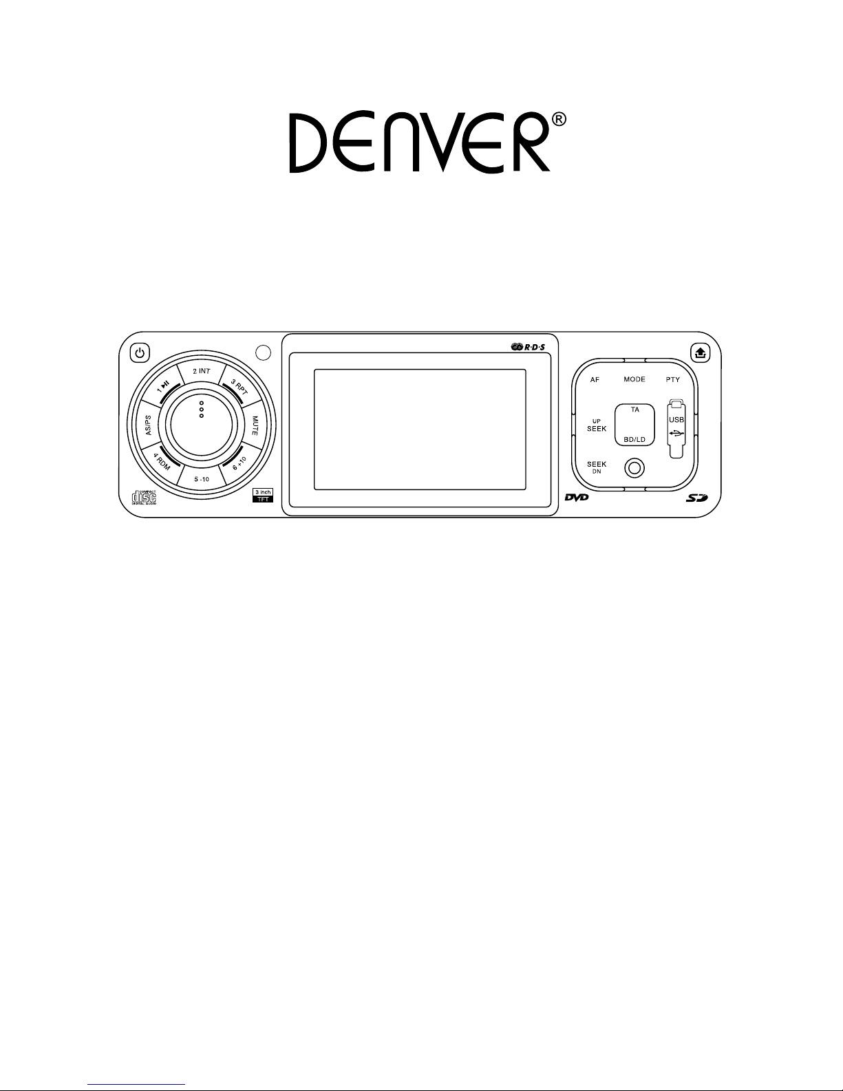
3” (7,6cm) TFT-LCD Display
USB / SD / MMC Card Input
Front AUX IN
Flip Down/Detachable Front Panel
CAT-131

EN1
BEFORE YOU BEGIN
PRECAUTIONS:
CAUTION:
USE OF CONTROLS OR ADJUSTMENT OR PERFORMANCE OF PROCEDURES OTHER
THAN THOSE SPECIFIED HEREIN MAY RESULT IN HAZARDOUS RADIATION EXPOSURE.
THE USE OF OPTICAL INSTRUMENTS WITH TH IS PRODUCT WILL I NC RE AS E EYE
HAZARD.
• Keep this manual handy as a reference for operating procedures and precautions.
• Always keep the volume low enough so you can hear sounds outside of the car.
• Protect this product from moisture.
• If the battery is disconnected or discharged, the preset memory will be erased and must be
reprogrammed.
FEATURES:
DVD video playback
It is possible to play back DVD video, DVD+-R, DVD+-RW and DVD+-DL.
Video CDs featuring PBC compatibility
It is possible to play back Video CDs featuring PBC (playback control).
CD playback
Music CD/CD-R/CD-RW playback is possible.
MP3/WMA le playback
It is possible to play back MP3/WMA les recorded on CD-ROM/CD-R/CD-RW.
MP4 le playback
It is possible to play back MP4 les.
PAL/NTSC compatibility
This unit is PAL/NTSC system compatible. When connecting other components to this unit, be
sure components are compatible with the same video system or else images will not be correctly
reproduced.
Multi-audio
You can switch between multiple audio systems recorded on a DVD as desired.
Multi-subtitle
You can switch between multiple subtitle languages recorded on a DVD as desired.
Multi-angle
You can switch between multiple viewing angles of a scene recorded on a DVD as desired.
When an operation is prohibited
When you are watching a DVD and attempt to perform an operation, it may not be performed by
the programming on the disc. When this happens, this unit indicates on the screen.
EN2
1
< 10°
2
182mm
53mm
3
4
TAP
1
2
3
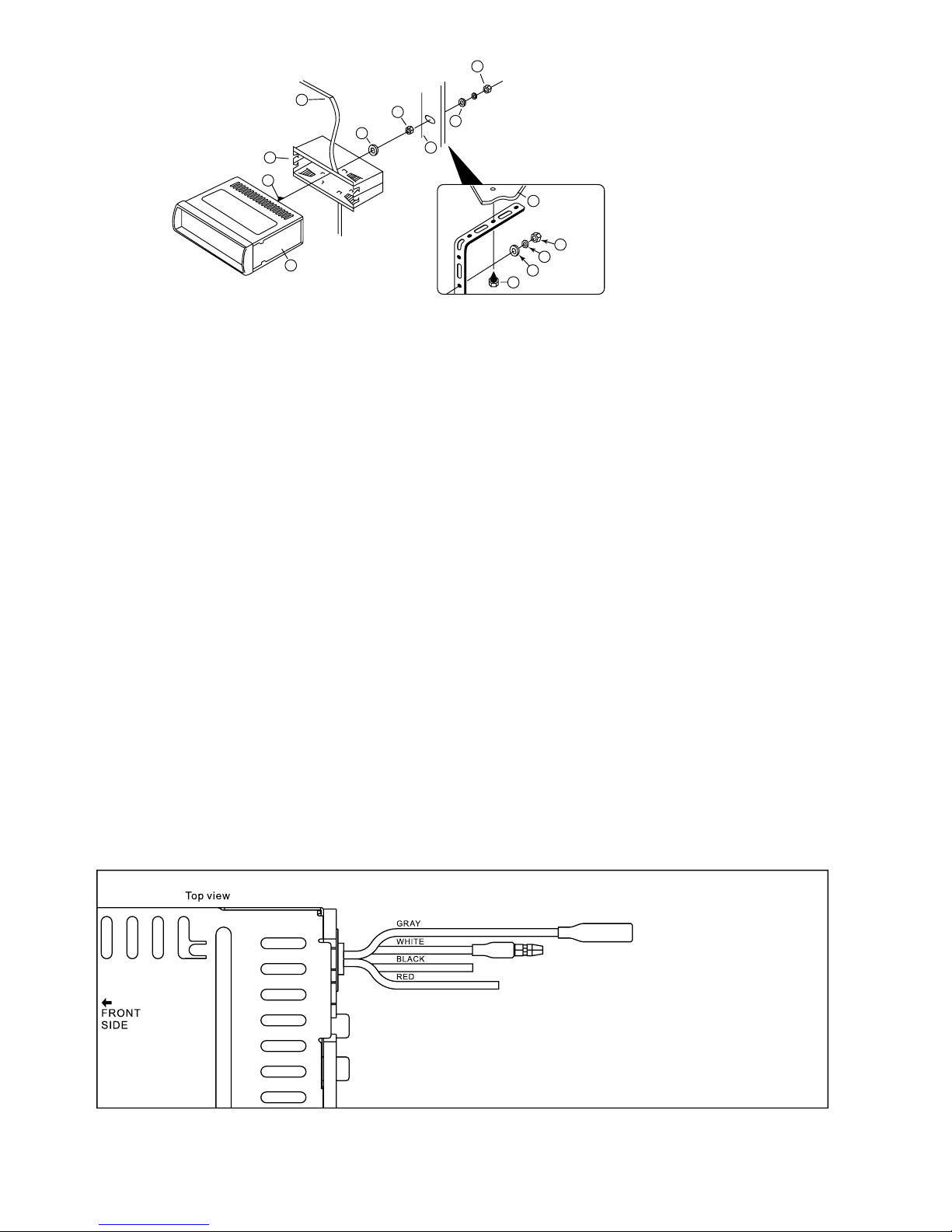
INSTALLATION
PRECAUTIONS
• Choose the mounting location carefully so that the unit will not interfere with the normal driving functions
of the driver.
• Avoid installing the unit where it would be subject to high temperatures, such as from direct sunlight
or hot air from the heater, or where it would be subject to dust, dirt or excessive vibration.
• Use only the supplied mounting hardware for a safe and secure installation.
• Be sure to remove the front panel before installing the unit.
NOTE :Inclination angle for car radio installation must not exceed 30˚ otherwise the front panel will not open.
NOTE: Keep the release key in the safe place as you may need it in future to remove the unit from the car.
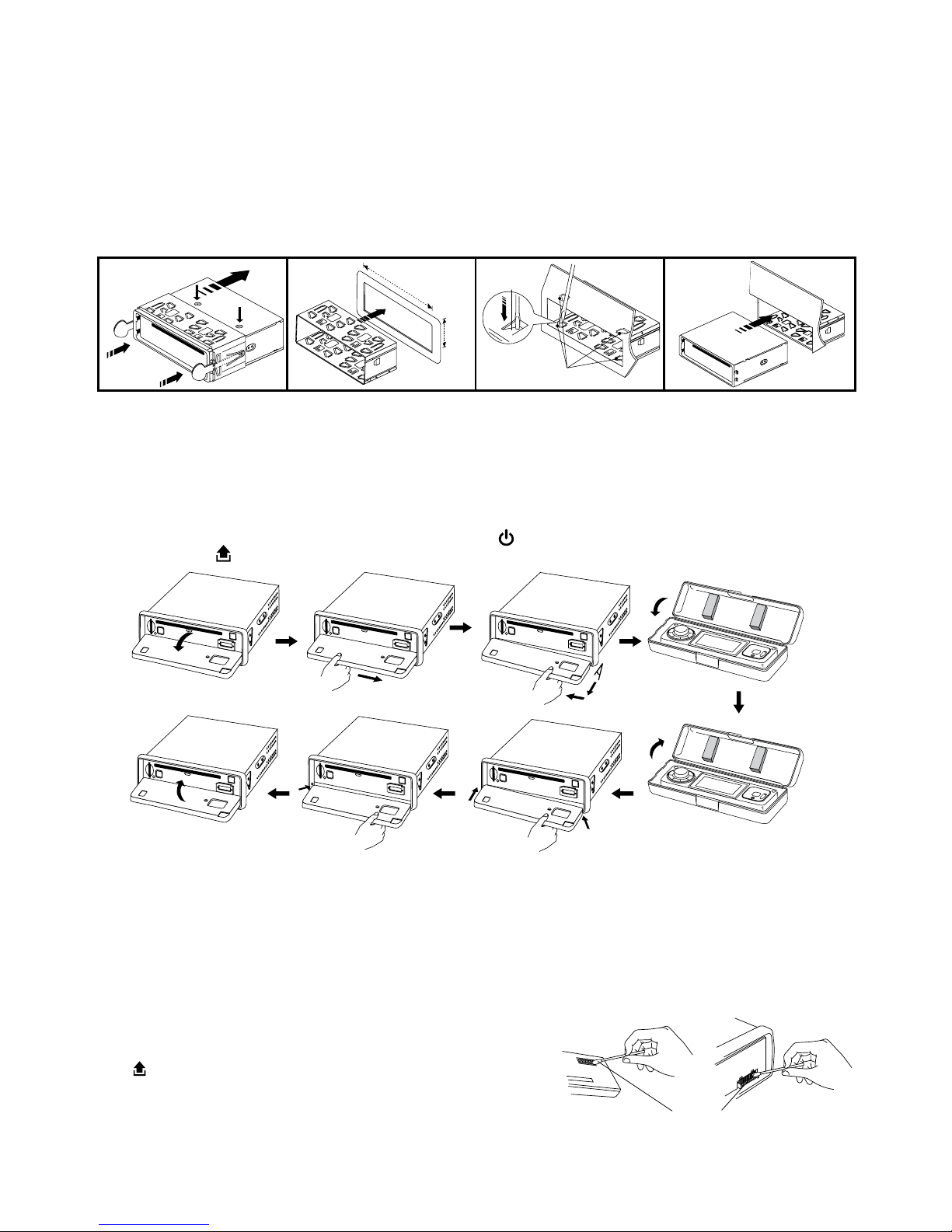
Detaching and attaching the front panel
The front panel of this unit can be detached in order to prevent the unit from being stolen.
FOLDING DOWN AND DETACHING/ATTACHING THE FRONT PANEL
Before detaching the front panel, be sure to press the button (1) OFF rst.
Then press the button and detach the panel by pulling it towards you as illustrated.
Notes:
• Do not press the front panel hard against the unit when attaching it. It can be easily attached by
pressing it lightly against the unit.
• When you carry the front panel with you, put it in the supplied front panel case.
• Do not press hard or give excessive pressure to the display window of the front panel when attaching
it to the unit.
CLEANING THE CONNECTOR
The unit may not function properly if the connectors between the
unit and the front panel are contaminated with dirt. In order to
prevent this from happening, detach the front panel by pressing
the
button and clean the connector from time to time.
Clean the connector with a cotton swab together with contact
cleaner as illustrated. Be sure to clean them carefully pin by pin
and make sure not to damage the connecting points.
Bend these
claws, if necessay
Release screw and
bracket
1
Cotton Swab
Rear of
front panel
Main unit
EN3
To Hand brake switch
10
7
1
2
3
4
4
4
5
5
6
6
8
9
1. UNIT
2. RELEASE CASE
3. DASH BOARD
4. HEX NUT
5. LOCK WASHER
6. PLAIN WASHER
7. CAR BODY
8. REAR SUPPORT STRAP
9. TAPPING SCREW
10. M5 X 15 HEX BOLT
Dashboard
WIRE CONNECTION
IN / OUT CONNECTOR
DVD Audio Out: White (L) Red (R)
Connect this wire to rear seat A/V monitor system to enjoy
DVD movie
Audio Out (Front): White (L) Red (R)
Audio Out (Rear): White (L) Red (R)
CONTROL WIRE
Parking (Gray) : Connect this wire to car hand brake system
Tel mute (Black) : Connect to mobile phone unit
When receiving calls, audio sound will be muted.
Rear camera (Red) : Connect to back rear camera
During back gear condition, this wire should be connected to high voltage.
DRIVING WITHOUT VIDEO DISPLAY
Follow the installation below so when the car is in motion, no video will come out from the LCD screen.
Only sound can be heard from speaker.
Note:
- Only sound can be heard when car is in motion.
- Refer and follow your country’s law regarding driving with video.
Caution:
- Do not attempt to install it by yourself if the instruction is not clear to you. Consult you dealer concerning
the installation procedures.
TO SUPPORT THE UNIT
Video Out (1/2) : Yellow
Connect to external A/V system to display
Video In : Yellow
Connect to external Video equipment
Rear camera In : Blue
Connect to rear camera output
Steps:
1. Connect the gray wire to the hand brake system.
2. Check your hand brake switch and make sure it
is connected to car bod y c hassis and pro pe rly
grounded.
EN4
To rear camera video out
To reverse gear control switch
To Hand brake switch
ANTENNA
CONNECTOR
FRONT
REAR
AUDIO OUT
CAMERA IN
VIDEO IN
VIDEO OUT 1
VIDEO OUT 2
R
L
L R
L R
ISO CONNECTOR
B
A
1234567
8
4
5 7
8
REAR
UT
CAMERA IN
VIDEO IN
R
L
L R
To Hand brake switch
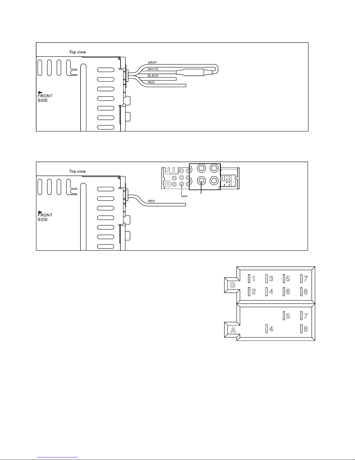
DRIVING WITH VIDEO DISPLAY
By following the installation below, video will always be shown on LCD screen no matter the car is in
motion or not.
INSTALLING REAR CAMERA FOR PARKING/REVERSE MOTION
You can install an separate camera at the car rear end so when doing parking or reverse motion, the unit
will automatically switch the video to the rear camera to guide the driver.
CONNECTOR A
4. MEMORY +12V
5. AUTO ANTENNA OUTPUT
7. +12V (TO IGNITION KEY)
8. GROUND
NOTE: (connector A no. 7) must be connected by car ignition key
in order to avoid that car battery becomes weak when the car will
be not used for long period.
CONNECTOR B
1. REAR RIGHT SPEAKER (+)
2. REAR RIGHT SPEAKER (-)
3. FRONT RIGHT SPEAKER (+)
4. FRONT RIGHT SPEAKER (-)
5. FRONT LEFT SPEAKER (+)
6. FRONT LEFT SPEAKER (-)
7. REAR LEFT SPEAKER (+)
8. REAR LEFT SPEAKER (-)
Maintenance
FUSE REPLACEMENT
If the fuse blows, check the power connection and replace the fuse. If the fuse blows again after the
replacement, there may be an internal malfunction. In this case, consult your nearest repairing center.
Warning
Use the specied amperage fuse for each lead. Use of a higher amperage fuse may cause serious damage.
B
1 3 5 7
2 4 6 8
5 7
4 8
A
Steps: Connect the GRAY wire to the WHITE wire.
Steps:
1. Connect the Rear Camera IN plug to the rear camera’s
video out plug.
2. Connect the RED wire to “REVERSE” gear control switch.
3. Check your gear control switch and make sure it is
connected to +12V.
 Loading...