

Denver CAD-495 Instruction Manual
INSTRUCTION MANUAL
CAR STEREO CD/CDR/CDRW/MP3/WMA PLAYER
WITH PLL FM STEREO RADIO
RDS
USB / SD / MMC CARD INPUT
DETACHABLE FRONT PANEL
CAD-495
PTY
AFTA
63
54
RELEASE
21
DISP
A/PS
PWR
BAND
TUNE/TRACK
SCN PAU INT RPT RDM
EJ
MD
V
O
L
P
U
S
H
S
E
L
E
C
T
E2
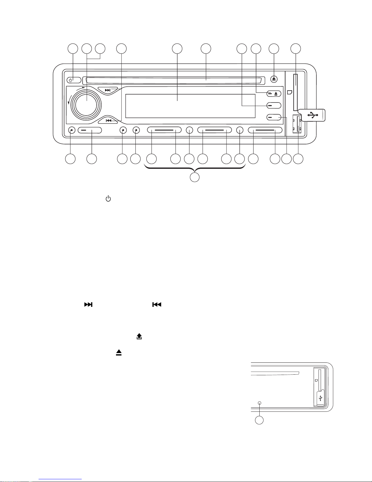
LOCATION OF PARTS AND CONTROLS
1. POWER ON/OFF ( )
2. FUNCTION SELECT BUTTON: BASS/TREBLE/BALANCE/FADER / TA SEEK/MASK DPI/
RETUNE/AUDIO DSP/LOUDNESS/CD MULTI/BEEP/SEEK/STEREO/LOCAL
3. VOL UP/VOL DOWN FOR BASS/TREBLE/BALANCE/FADER / TA SEEK/MASK DPI/RETUNE/
AUDIO DSP/LOUDNESS/CD MULTI/BEEP/SEEK/STEREO/LOCAL
4. PRESET STATIONS (1,2,3,4,5,6)
5. ‘AF’ function (ALTERNATIVE FREQUENCIES)
6. ‘TA’ function (TRAFFIC ANNOUNCEMENT)
7. ‘PTY’ function (PROGRAM TYPE)
8. DISPLAY BUTTON (DISP)
9. MODE BUTTON (MD)
10. BAND BUTTON (BAND)
11. AUTOMATIC OR MANUAL TUNING
(FREQ UP OR FREQ DOWN )/CD TRACK/SEARCH BUTTON
12. AUTO SEEK SEARCH TUNING (A/PS)
13. ‘SCAN’ AUTOMATIC TUNING CONTROL (SCN)
14. LCD DISPLAY
15. PANEL RELEASE BUTTON ( )
16. CD SLOT
17. CD EJECT BUTTON ( )
18. PAUSE BUTTON
19. INTRO BUTTON (Preview all Tracks)
20. REPEAT BUTTON
21. RANDOM BUTTON
22, 23. + 10 TRACK SEARCH DOWN/UP
24. USB PORT
25. MULTI-MEDIA CARD (MMC) / SD CARD SLOT
26. RESET BUTTON
PTY
AFTA
63
54
RELEASE
21
DISP
A/PS
PWR
BAND
TUNE/TRACK
SCN PAU INT RPT RDM
EJ
MD
V
O
L
P
U
S
H
S
E
L
E
C
T
4
(1-6)
15179
25161 2 3 1411
245 762322212019181310812
PTY
AFTA
63
54
RELEASE
21
DISP
A/PS
PWR
BAND
TUNE/TRACK
SCN PAU INT RPT RDM
EJ
MD
V
O
L
P
U
S
H
S
E
L
E
C
T
PTY
AFTA
63
54
RELEASE
21
SCN PAU INT RPT RDM
EJ
MD
4
(1-6)
15179
25161 2 3 1411
245 762322212019181310812
PTY
AFTA
63
54
RELEASE
21
SCN PAU INT RPT RDM
EJ
MD
26
RESET
E3
10
7
1
2
3
4
4
4
5
5
6
6
8
9
53mm
182mm
3
2
182mm
53mm
1
2
1
3
4
release screw and
bracket
Bend these
claws, if necessary
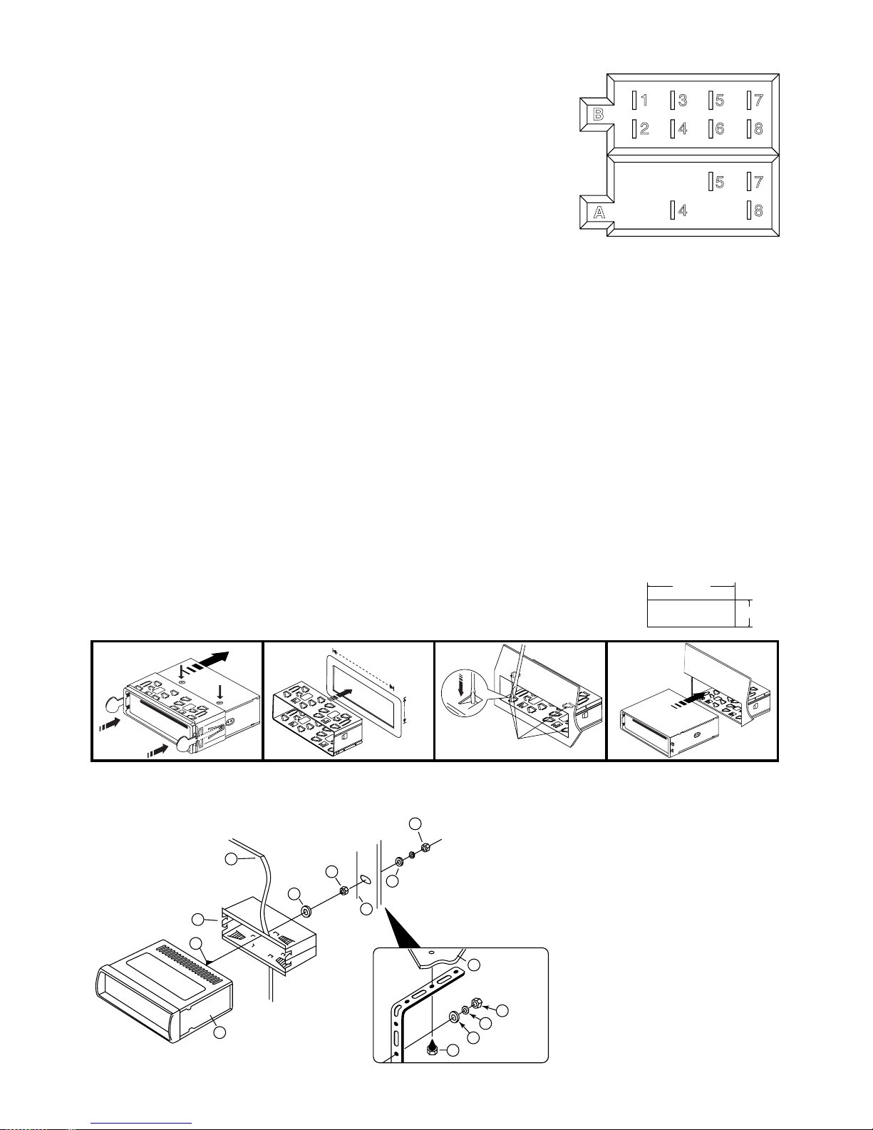
ISO CONNECTOR
RCA Line Out: Red (right) White (left)
RCA Line In: Red (right) White (left)
CONNECTOR A
4. MEMORY +12V
5. AUTO ANTENNA OUTPUT
7. +12V (TO IGNITION KEY)
8. GROUND
Note: (connector A no. 7) must be connected by car ignition key in order to avoid
that car battery becomes weak when the car will be not used for long period.
CONNECTOR B
1. REAR RIGHT SPEAKER (+)
2. REAR RIGHT SPEAKER (-)
3. FRONT RIGHT SPEAKER (+)
4. FRONT RIGHT SPEAKER (-)
5. FRONT LEFT SPEAKER (+)
6. FRONT LEFT SPEAKER (-)
7. REAR LEFT SPEAKER (+)
8. REAR LEFT SPEAKER (-)
Maintenance
FUSE REPLACEMENT
If the fuse blows, check the power connection and replace the fuse. If the fuse blows again after the replacement, there
may be an internal malfunction. In this case, consult your nearest repairing center.
Warning
Use the specied amperage fuse for each lead. Use of a higher amperage fuse may cause serious damage.
B
1 3 5 7
2 4 6 8
5 7
4 8
A
1. UNIT
2. RELEASE CASE
3. DASH BOARD
4. HEX NUT
5. LOCK WASHER
6. PLAIN WASHER
7. CAR BODY
8. REAR SUPPORT STRAP
9. TAPPING SCREW
10. M5 X 15 HEX BOLT
Dashboard
INSTALLATION
PRECAUTIONS
• Choose the mounting location carefully so that the unit will not interfere with the normal driving functions of the
driver.
• Avoid installing the unit where it would be subject to high temperatures, such as from direct sunlight or hot air from
the heater, or where it would be subject to dust, dirt or excessive vibration.
• Use only the supplied mounting hardware for a safe and secure installation.
• Be sure to remove the front panel before installing the unit.
NOTE : Inclination angle for car radio installation must not
exceed 30˚ otherwise the front panel will not open.
Note: Keep the release key in a safe place as you may need it in future to remove the unit from the car.
TO SUPPORT THE UNIT
 Loading...