

Denver CAD-471, CAD-452 Bluetooth Instruction Manual
INSTRUCTION MANUAL
Car Stereo CD/CDR/CDRW/MP3 Player
with PLL FM Stereo Radio
RDS
USB / MMC / SD Card Input
Bluetooth Function in Mobile Phone
Flip Down and Detachable Front Panel System
CAD-471
E1
8 6 27262524222014 151013 23 12
16 17751 9 2 311 21
4
(1-6)
28
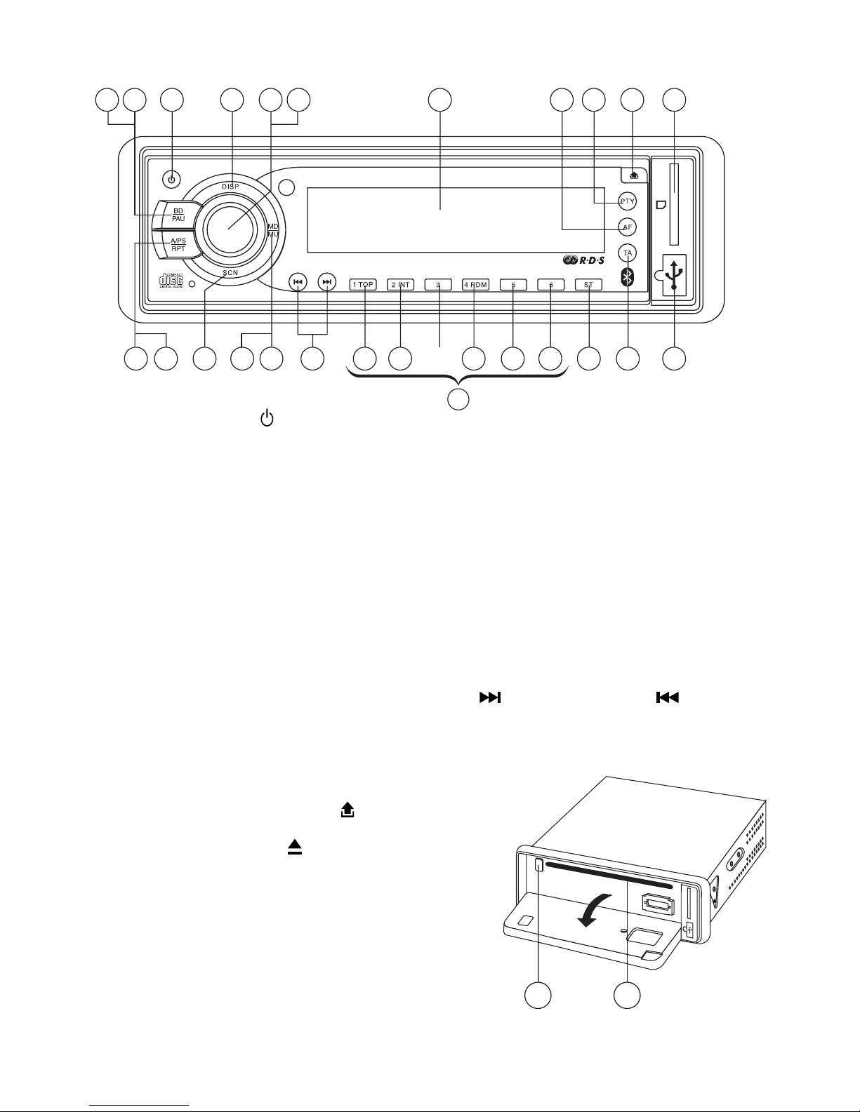
LOCATION OF PARTS AND CONTROLS
1. POWER ON/OFF ( )
2. FUNCTION SELECT BUTTON: BASS/TREBLE/BALANCE/FADER/TA SEEK/MASK DPI/
RETUNE/AUDIO DSP/LOUDNESS/ESP/CD MULTI/SCROLL/BEEP/STEREO/
LOCAL/PAIRING
3. VOL UP/VOL DOWN FOR BASS/TREBLE/BALANCE/FADER/TA SEEK/MASK DPI/
RETUNE/AUDIO DSP/LOUDNESS/ESP/CD MULTI/SCROLL/BEEP/STEREO/
LOCAL/PAIRING
4. PRESET STATIONS (1,2,3,4,5,6)
5. ‘AF’ function (ALTERNATIVE FREQUENCIES)
6. ‘TA’ function (TRAFFIC ANNOUNCEMENT)
7. ‘PTY’ function (PROGRAM TYPE)
8. STEREO/MONO BUTTON (ST)
9. DISPLAY BUTTON (DISP)
10. MODE BUTTON (MD)
11. BAND BUTTON (BD)
12. AUTOMATIC OR MANUAL TUNING (FREQ UP OR FREQ DOWN /
CD TRACK/SEARCH BUTTON
13. AUTO SEEK SEARCH TUNING (A/PS)
14. ‘SCAN’ AUTOMATIC TUNING CONTROL (SCN)
15. MUTE BUTTON (MU)
16. LCD DISPLAY
17. PANEL RELEASE BUTTON ( )
18. CD SLOT
19. CD EJECT BUTTON ( )
20. TOP BUTTON
21. PAUSE BUTTON
22. INTRO BUTTON (Preview all Tracks)
23. REPEAT BUTTON
24. RANDOM BUTTON
25, 26. + 10 TRACK SEARCH DOWN/UP
27. USB PORT
28. MULTI-MEDIA CARD (MMC) / SD CARD SLOT
19 18
8 6 27262524222014 151013 23 12
16 17751 9 2 311 21
4
(1-6)
28
E2
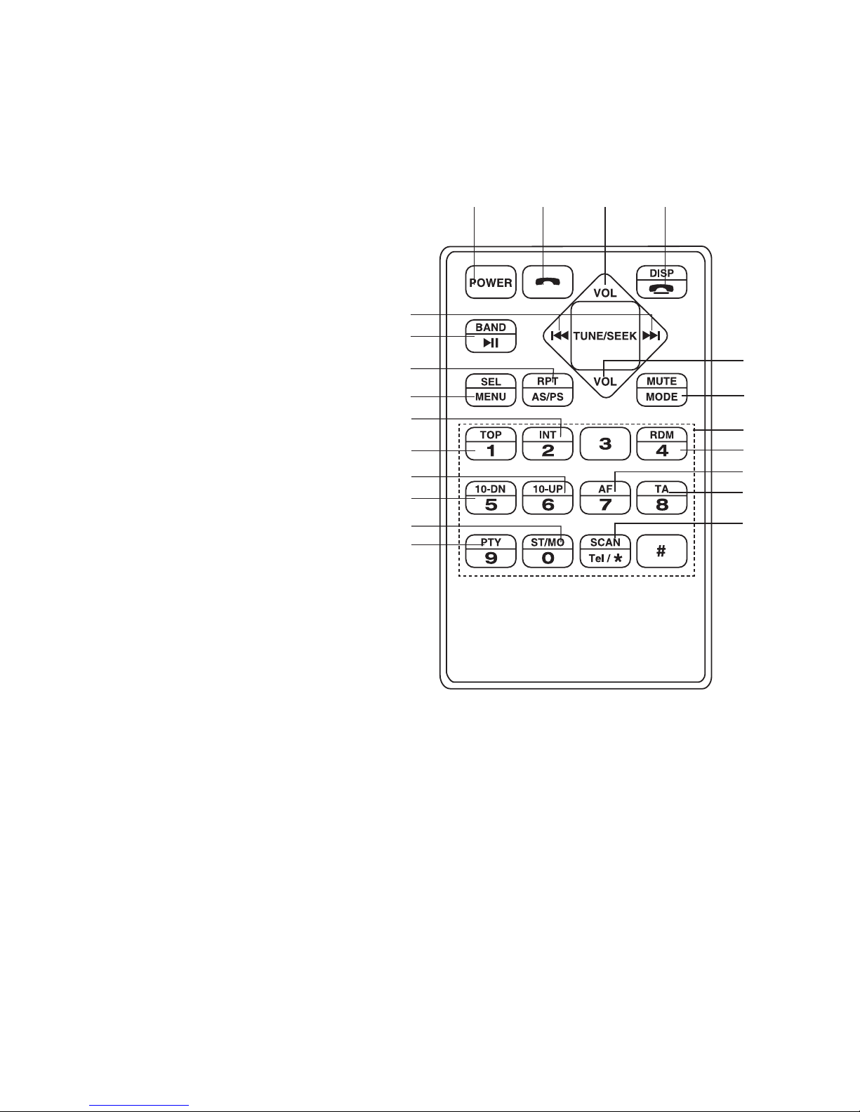
1. POWER ON / OFF
2. ANSWER A CALL
3. VOLUME +
4. DISP / END A CALL
5. BAND / CD PLAY / PAUSE
6. TUNE / SEEK
7. SEL / MENU
8. CD REPEAT /
AUTO STORE / PRESET SCAN
9. VOLUME -
10. MUTE / MODE
11. CD PLAYER FIRST SONG
12. CD INTRO
13. PHONE NUMBER /
BUTTON 1-6: STATION
PRESETS
14. CD RANDOM
15. 10 TRACK DOWN SELECT
16. 10 TRACK UP SELECT
17. ALTERNATIVE FREQUENCIES
18. TRAFFIC ANNOUNCEMENT
19. PROGRAM TYPE
20. STEREO / MONO MODE
21. RADIO SCAN / PHONE
1
5
32 4
6
7
8
9
10
11
12
13
14
15
16
20
21
17
18
19
REMOTE CONTROLS FUNCTIONS
E3
53mm
182mm
3
2
182mm
53mm
1
2
1
3
4
INSTALLATION
PRECAUTIONS
• Choose the mounting location carefully so that the unit will not interfere with the normal
driving functions of the driver.
• Avoid installing the unit where it would be subject to high temperatures, such as from direct
sunlight or hot air from the heater, or where it would be subject to dust, dirt or excessive
vibration.
• Use only the supplied mounting hardware for a safe and secure installation.
• Be sure to remove the front panel before installing the unit.
NOTE : Inclination angle for car radio installation must not
exceed 30˚ otherwise the front panel will not open.
Note: Keep the release key in a safe place as you may need it in the future to remove the
unit from the car.
Bend these
claws, if necessary
release screw and
bracket
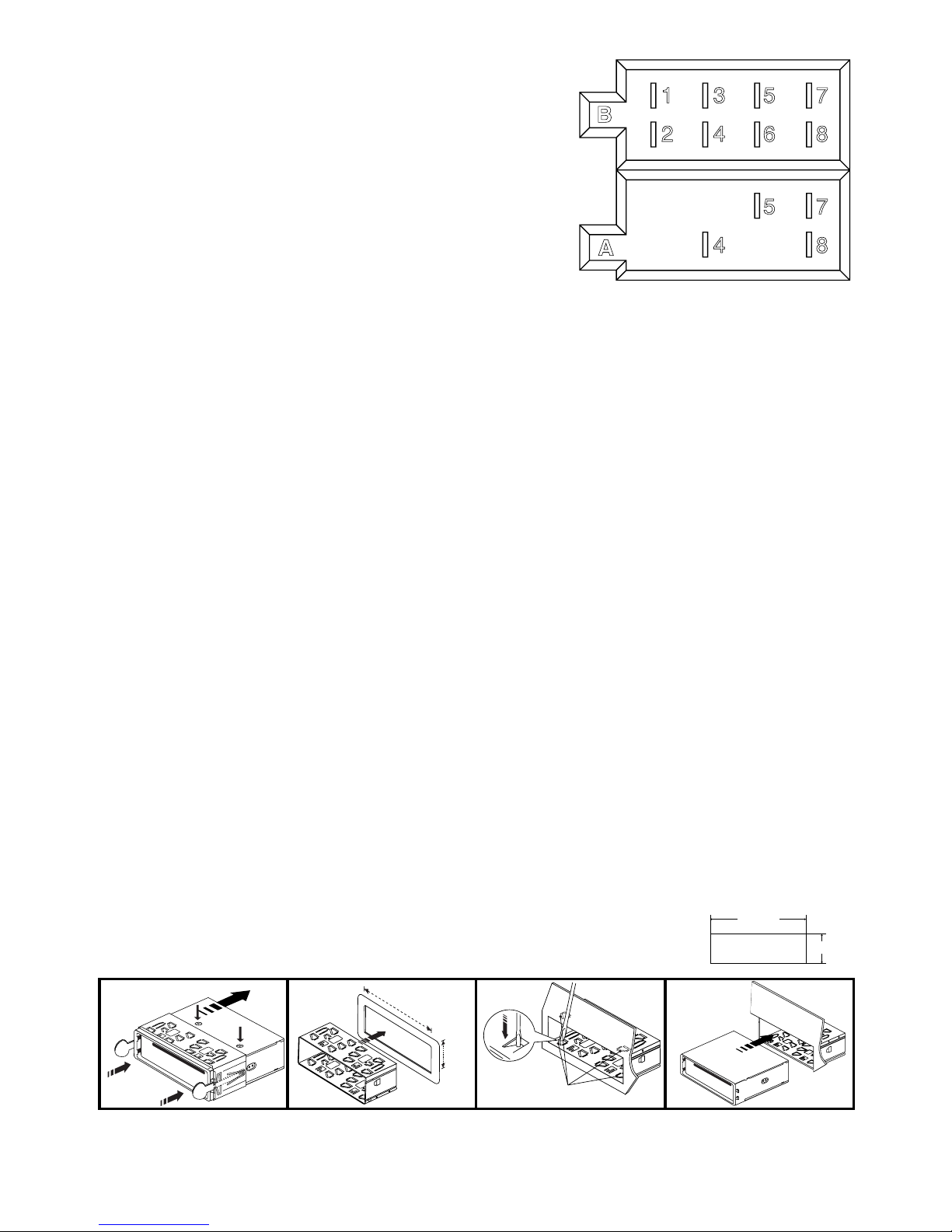
ISO CONNECTOR
RCA Jack Line Out : Red (right) White (left)
RCA Jack Line In : Red (right) White (left)
CONNECTOR A
1.
2.
3.
4. MEMORY +12V
5. AUTO ANTENNA OUTPUT
6.
7. +12V (TO IGNITION KEY)
8. GROUND
Note: (connector A no. 7) must be connected by car ignition key in order to avoid that car
battery being drained when the car will be not used for long period.
CONNECTOR B
1. REAR RIGHT SPEAKER (+)
2. REAR RIGHT SPEAKER (-)
3. FRONT RIGHT SPEAKER (+)
4. FRONT RIGHT SPEAKER (-)
5. FRONT LEFT SPEAKER (+)
6. FRONT LEFT SPEAKER (-)
7. REAR LEFT SPEAKER (+)
8. REAR LEFT SPEAKER (-)
Maintenance
FUSE REPLACEMENT
If the fuse blows, check the power connection and replace the fuse. If the fuse blows again after the
replacement, there may be an internal malfunction. In this case, consult your nearest repair center.
Warning
Use the specied amperage fuse for each lead. Use of a higher amperage fuse may cause serious damage.
B
1 3 5 7
2 4 6 8
5 7
4 8
A
 Loading...