

Denver CAD-350 Instruction Manual
E1
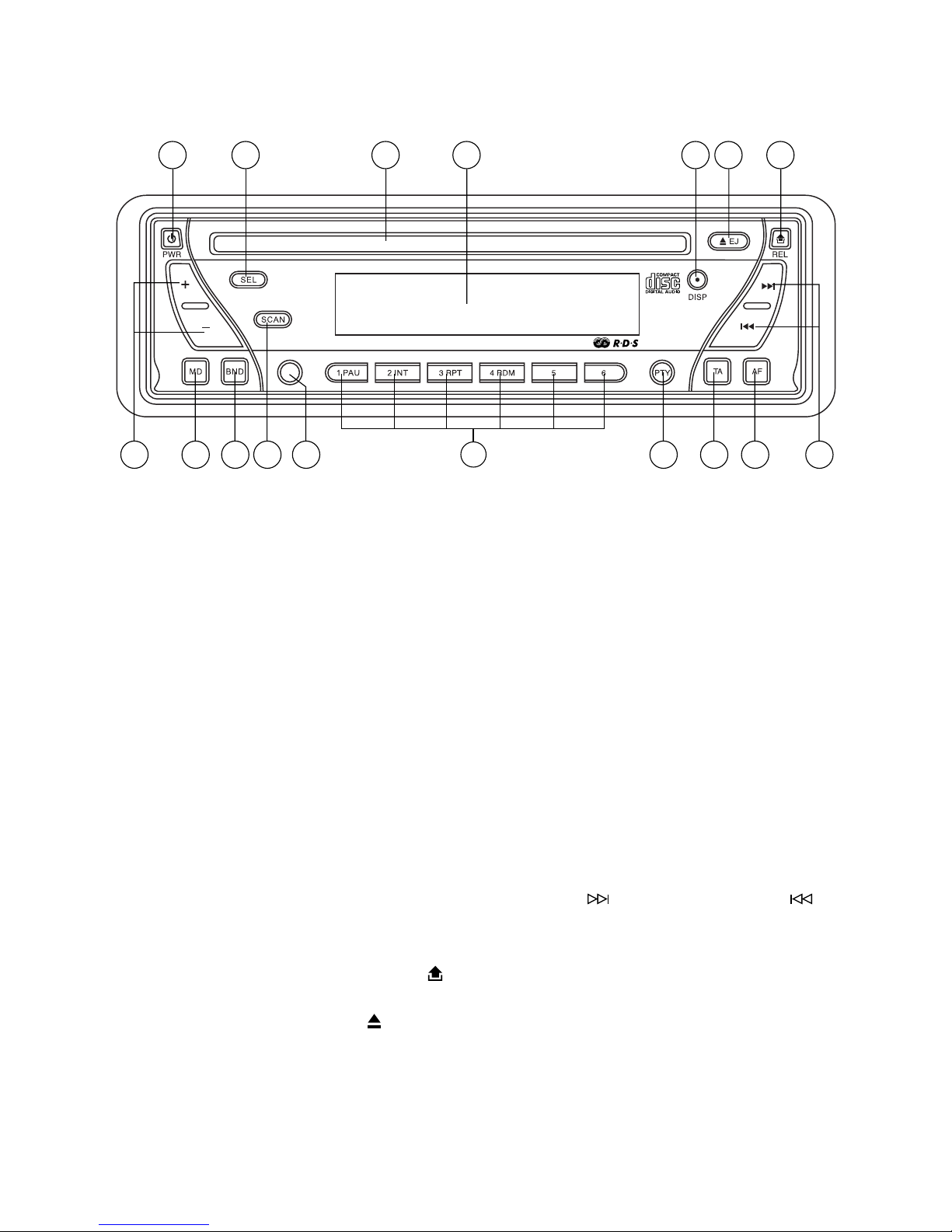
LOCATION OF PARTS AND CONTROLS
1. POWER ON/OFF (PWR)
2. FUNCTION SELECT BUTTON: BASS/TREBLE/BALANCE/F ADER/T A SEEK/
MASK DPI/RETUNE/AUDIO DSP/LOUDNESS/ESP/BEEP/SEEK/STEREO/
LOCAL/VOL LAST (SEL)
3. VOL UP/VOL DOWN FOR BASS/TREBLE/BALANCE/FADER/TA SEEK/
MASK DPI/RETUNE/AUDIO DSP/LOUDNESS/ESP/BEEP/SEEK/STEREO/
LOCAL/VOL LAST (+/-)
4. PRESET STATIONS (1,2,3,4,5,6)
5. 'AF' function (ALTERNATIVE FREQUENCIES)
6. 'TA' function (TRAFFIC ANNOUNCEMENT)
7. 'PTY' function (PROGRAM TYPE)
8. DISPLAY (DISP)
9. MODE BUTTON (MD)
10. BAND (BND)
1 1. AUTOMATIC OR MANUAL TUNING (FREQ UP
OR FREQ DOWN )
12. AUTO SEEK SEARCH TUNING (A/PS)
13. ‘SCAN’ AUT OMA TIC TUNING CONTROL (SCAN)
14. PANEL RELEASE BUTTON (
)
15. LCD DISPLAY
16. CD EJECT BUTTON (
)
17. CD SLOT
A/PS
1 17 15 16 1482
93 10 7 6 5 111213
4
(1-6)
E2
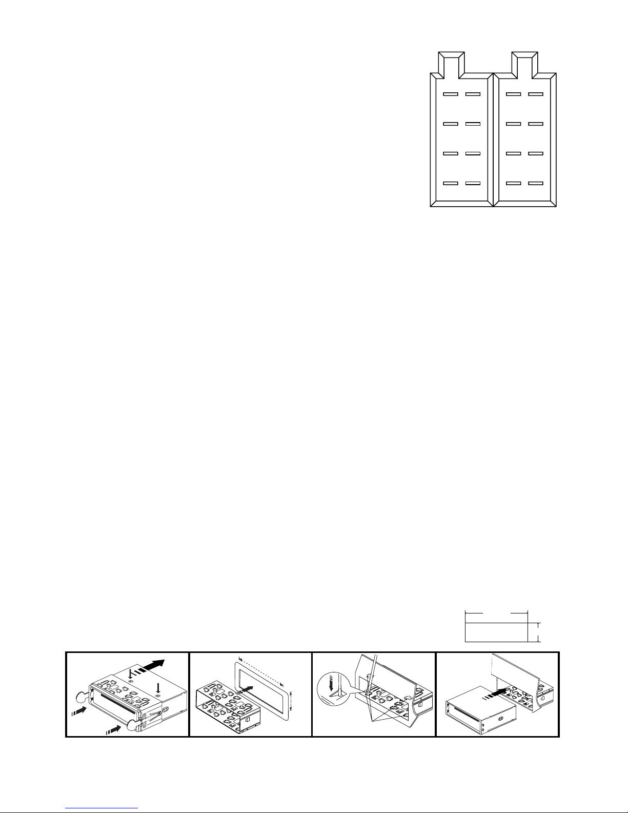
INSTALLATION
PRECAUTIONS
• Choose the mounting location carefully so that the unit will not interfere with the normal
driving functions of the driver.
• Avoid installing the unit where it would be subject to high temperatures, such as from
direct sunlight or hot air from the heater, or where it would be subject to dust, dirt or
excessive vibration.
• Use only the supplied mounting hardware for a safe and secure installation.
• Be sure to remove the front panel before installing the unit.
NOTE : Inclination angle for car radio installation must not
exceed 30˚ otherwise the front panel will not open.
Note: Keep the release key in the safe place as you may need it in future to remove the unit
from the car.
Bend these
claws, if necessay
release screw and
bracket
53mm
182mm
3
2
182mm
53mm
1
2
1
3
4
ISO CONNECTOR
RCA Jack Line Out: RCA Jack Line In:
: Red (right) : Red (right)
: White (left) : White (left)
CONNECTOR A
1.
2.
3.
4. MEMORY +12V
5. AUTO ANTENNA OUTPUT
6.
7. +12V (TO IGNITION KEY)
8. GROUND
Note: (connector A no. 7) must be connected by car ignition key in order to avoid that car
battery becomes weak when the car will be not used for long period.
CONNECTOR B
1. REAR RIGHT SPEAKER (+)
2. REAR RIGHT SPEAKER (-)
3. FRONT RIGHT SPEAKER (+)
4. FRONT RIGHT SPEAKER (-)
5. FRONT LEFT SPEAKER (+)
6. FRONT LEFT SPEAKER (-)
7. REAR LEFT SPEAKER (+)
8. REAR LEFT SPEAKER (-)
Maintenance
FUSE REPLACEMENT
If the fuse blows, check the power connection and replace the fuse. If the fuse blows again after the
replacement, there may be an internal malfunction. In this case, consult your nearest repairing center.
Warning
Use the specified amperage fuse for each lead. Use of a higher amperage fuse may cause serious
damage.
B
12
34
56
78
12
34
56
78
A
E3
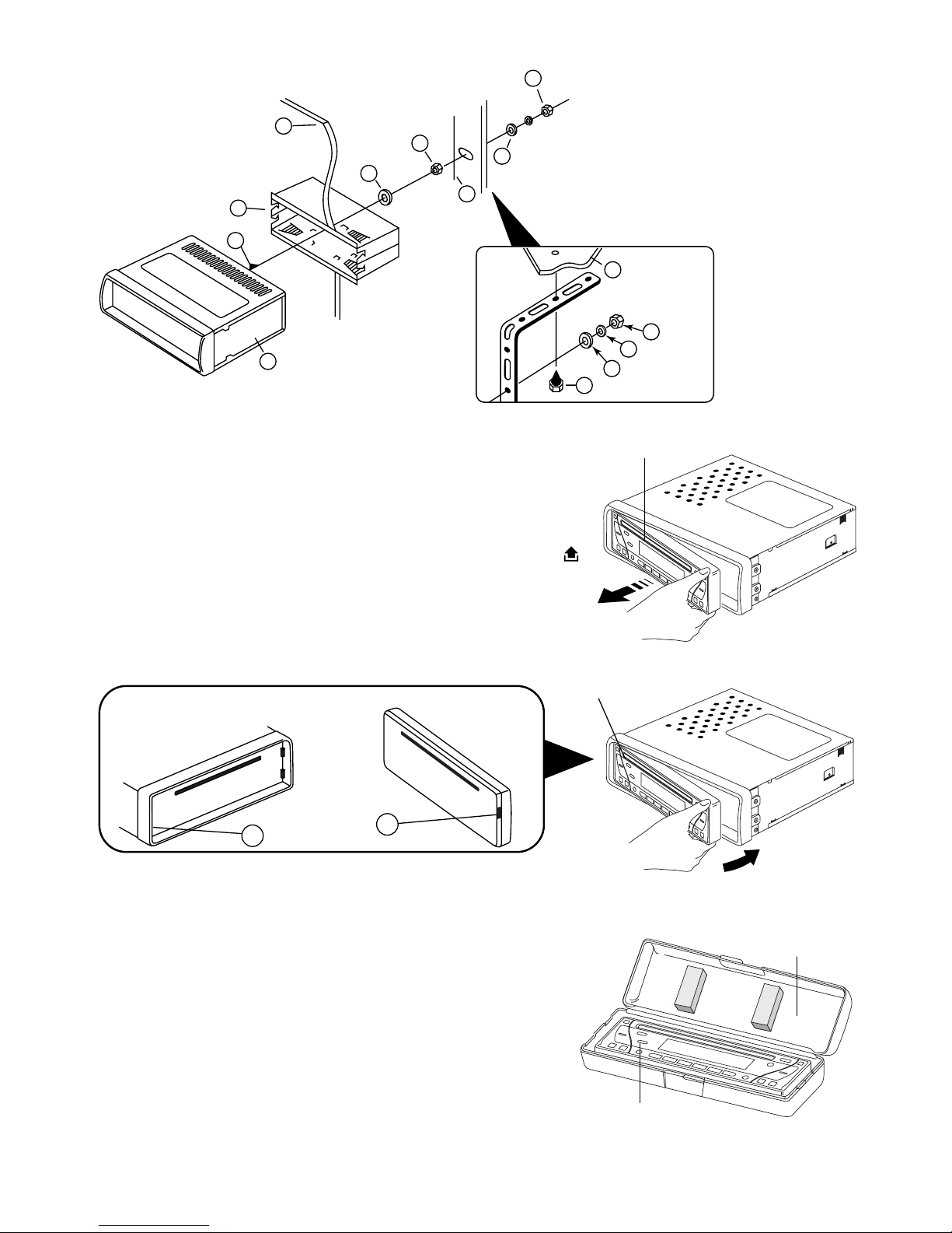
TO SUPPORT THE UNIT
Detaching and attaching the front panel
The front panel of this unit can be detached in order to
prevent the unit from being stolen.
DETACHING THE FRONT PANEL
Before detaching the front panel, be sure to press the
POWER OFF button first. Then press the button (14)
and detach the panel by pulling it towards you as
illustrated.
Note:
Be sure not to drop the panel when detaching it from the
unit.
Notes:
• Make sure that the front panel is the right way up
when attaching it to the unit as it cannot be attached
upside down.
• Do not press the front panel hard against the unit
when attaching it. It can be easily attached by
pressing it lightly against the unit.
• When you carry the front panel with you, put it in the
supplied front panel case.
• Do not press hard or give excessive pressure to the
display window of the front panel when attaching it
to the unit.
B
A
Front panel
Main unit
Rear of the front panel
Front panel
1. UNIT
2. RELEASE CASE
3. DASH BOARD
4. HEX NUT
5. LOCK WASHER
6. PLAIN WASHER
7. CAR BODY
8. REAR SUPPORT STRAP
9. T APPING SCREW
10.M5 X 15 HEX BOLT
Dashboard
10
7
1
2
3
4
4
4
5
5
6
6
8
9
Panel case
Front panel
 Loading...