

Page 1
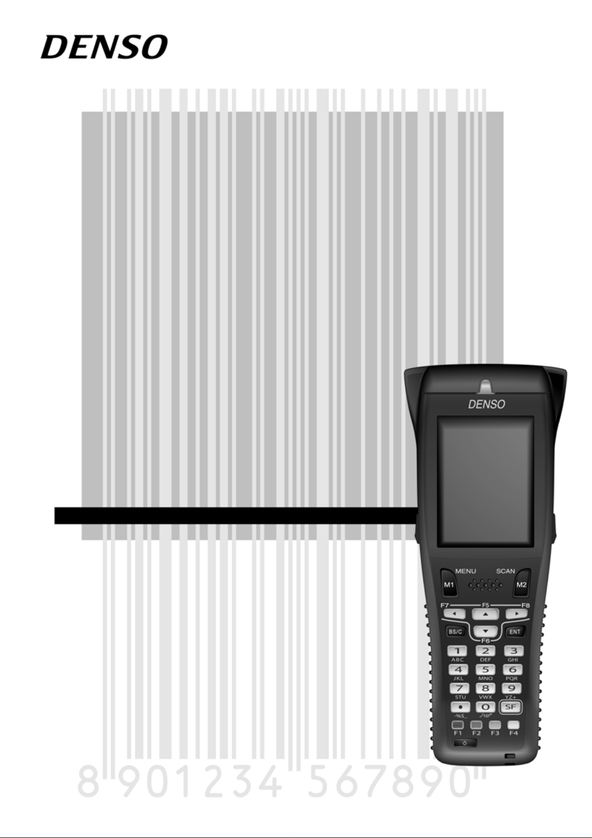
Barcode Handy Terminal
BHT-805B
User’s Manual
Page 2

BHT-805B
Preface
Thank you for using the BHT-805B DENSO WAVE Barcode Handy Terminal.
Please read this manual thoroughly prior to operation to ensure full use of the product’s functionality, and store safely
in a convenient location for quick reference even after reading.
Liability Limitations
• DENSO WAVE INCORPORATED ("DENSO WAVE") does not assume any product liability (including damages
for lost profits, interruption of operations, or the loss of business-related information) arising out of, or in
connection with, the use of, or inability to use the BHT system software or related manuals.
• DENSO WAVE takes reasonable precautions to ensure its products do not infringe upon any patents or other
intellectual property rights of other(s). However, DENSO WAVE cannot be responsible for any patent or other
intellectual property right infringement(s) or violation(s) arising from any of the following.
1) The use of DENSO WAVE's products in connection or in combination with other components, products,
devices, data processing systems or software not supplied by DENSO WAVE.
2) The use of DENSO WAVE's products in a manner for which they were not intended nor designed.
3) The modification of DENSO WAVE's products by parties other than DENSO WAVE.
• If it is judged by DENSO WAVE that malfunction of the product is due to the product having been dropped or
subjected to impact, repairs will be made at a reasonable charge even within the warranty period.
i
Page 3

Barcode Handy Terminal
Customer Registration and Inquiries
Customer Registration
To allow us to provide our customers with comprehensive service and support, we request that all customers
complete a Member Registration Form. Registered members will be offered the following privileges.
• The latest upgrade information
• Free exhibition and event information for new products
• Free web-information service "QBdirect".
QBdirect Service Contents
Information search
service (FAQ)
Download service The latest OS systems for the BHT series, repair software, and sample
E-mail inquiries Product related queries can be sent in by e-mail.
* Please note that these privileges may be subject to change without prior notice.
− How to Register
Access the URL below and follow the instructions provided.
http://www.qbdirect.net/
Offers detailed information on each product.
programs can be downloaded.
Inquiries
− Technical Inquiries (QBdirect)
• BHT product programming method
• Product setup method, usage
• Other technical questions
Inquires relating to the above can be made at our exclusive Web site for registered users (QBdirect).
Access the link below to log on or register.
http://www.qbdirect.net/
ii
Page 4

BHT-805B
About this Manual
• Due to changes and improvements, the content of this manual may be subject to change without prior notice.
• The reproduction or duplication of the whole or part of this manual is strictly prohibited without prior consent.
• Every attempt has been made to ensure that the content of this manual is thorough and up to date, however, we
kindly ask you to report any questionable descriptions, mistakes, or omissions, if any, to DENSO WAVE.
• The copyright for this User’s Manual belongs to DENSO WAVE INCORPORATED.
Manual Composition
This manual is made up of the following 9 chapters.
Chapter 1 Outline
Describes the BHT system and provides an overall outline of the BHT.
Chapter 2 BHT Preparation
Describes information required by the user and procedures that must be performed prior to
commencing operation.
Chapter 3 Basic Operation
Describes basic operations performed by the operator and how to make basic changes to settings such
as the volume.
Chapter 4 System Operation
Describes how to initialize and update the system, start up a user program, and operate System Mode.
Chapter 5 Communication
Describes interfaces and communication specifications.
Chapter 6 Maintenance
Describes battery cartridge replacement and daily procedures for taking care of the BHT.
Chapter 7 Error Messages
Describes causes and countermeasures for error messages expected to occur during basic operation.
Chapter 8 Specifications
Describes specifications for hardware, readable barcodes, and interfaces.
Appendices-1 CU-800 Specifications (Option)
Describes the main specifications for the CU-800 Series (option).
Appendices-2 When File Transfer is Not Possible Using the Transfer Utility
Describes causes and countermeasures when unable to transfer files.
iii
Page 5
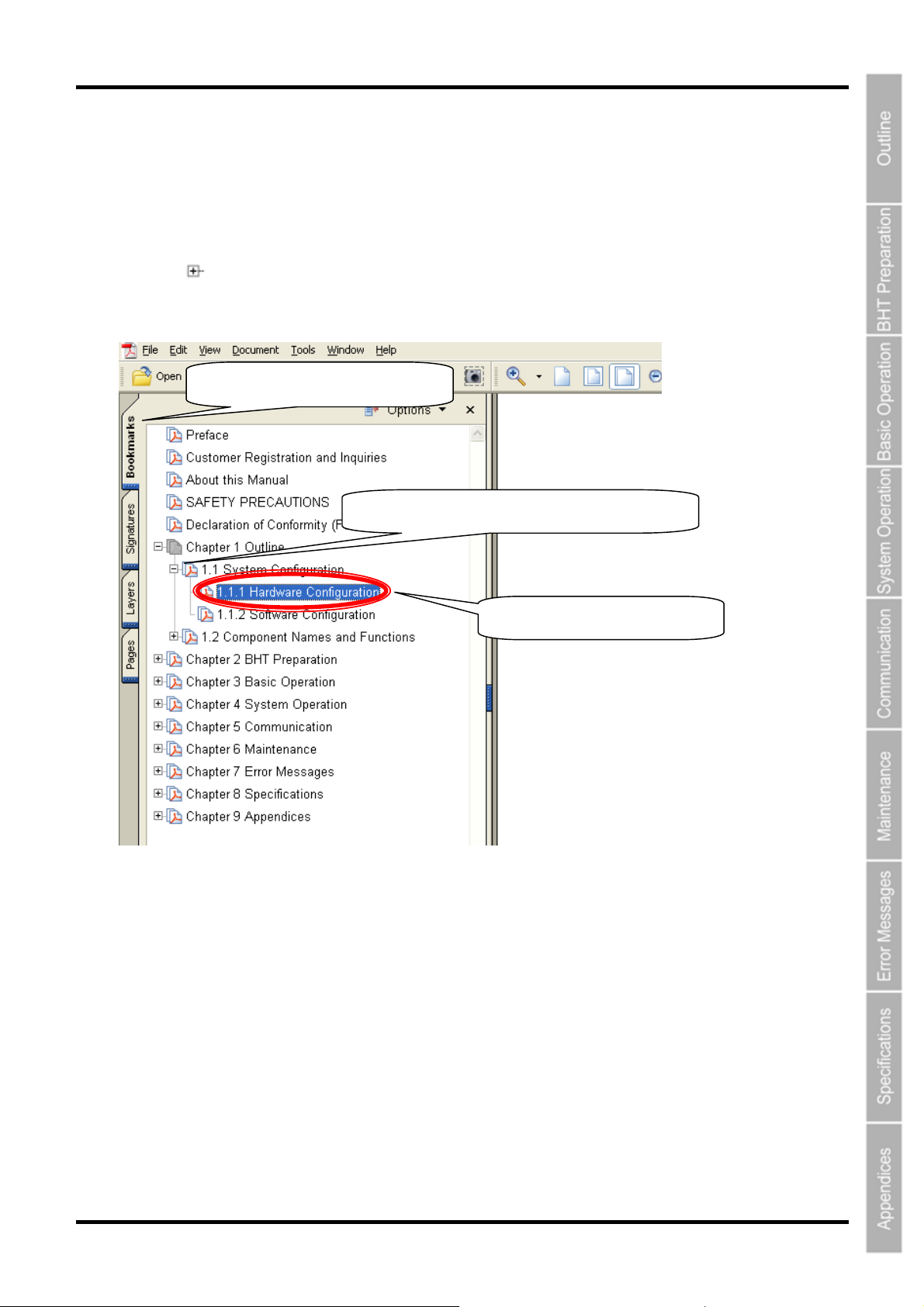
Viewing this Manual
− About the Bookmark
The PDF Bookmark function can be used to jump to the Contents page.
<Procedure>
(1) Click the “Bookmark” tab.
(2) Click
(3) Click the item to be read.
to search for the desired item.
(1) Click the “Bookmarks” tab.
(2) Click “+” to search for the desired item.
(3) Click the item to be read.
Barcode Handy Terminal
iv
Page 6
BHT-805B
805
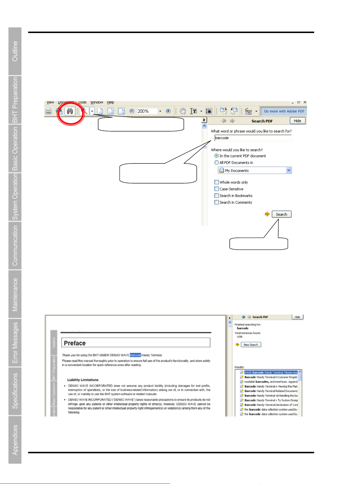
− Searching by Word
The PDF search function can be used to jump to the target page by entering words or characters related to the
item being searched.
(1) Click the Search icon. (Or select “Edit” – “Search”.)
(2) Enter the word(s) or character(s) to be searched for.
(3) Click [Search].
<Search Results Example>
BHT-
B
(1) Click the Search icon.
(2) Enter the search word(s)
or character(s).
(3) Click [Search].
v
Page 7

Related Documentation
• BHT-BASIC Programmer’s Manual (BHT-800 Series)
This is an instruction manual used to create handy terminal programs with BHT-BASIC.
• BHT-BASIC 4.0 Transfer Utility User’s Guide
This is an instruction manual for software relating to data transfer between the computer and BHT-800 and
comes bundled with the BHT-BASIC 4.0 Transfer Utility.
Barcode Handy Terminal
vi
Page 8
BHT-805B
SAFETY PRECAUTIONS
Be sure to observe all these safety precautions.
Please READ through this manual carefully. It will enable you to use the BHT and CU correctly.
Always keep this manual nearby for speedy reference.
Strict observance of these warnings and cautions is a MUST for preventing accidents that could result in bodily injury
and substantial property damage. Make sure you fully understand all definitions of these terms and symbols given
below before you proceed to the text itself.
Alerts you to those conditions that could cause serious bodily injury or death if the instructions
are not followed correctly.
Alerts you to those conditions that could cause minor bodily i njury or substantial property
damage if the instructions are not followed correctly.
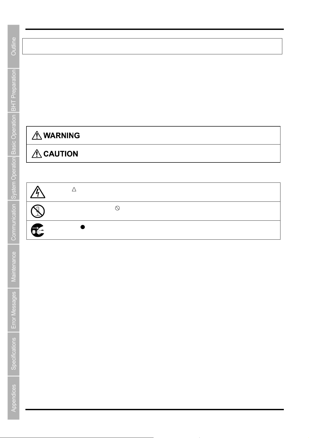
Meaning of Symbols
A triangle (
shock.
A diagonal line through a circle (
inside. Here you see a screwdriver inside the circle, meaning that you should not disass emble.
A black circle (
MUST unplug the power cord.
) with a picture inside alerts you to a warning of danger. Here you see the warning for electrical
) warns you of something you should not do; it may or may not have a picture
) with a picture inside alerts you to something you MUST do. This example shows that yo u
vii
Page 9
Handling the battery cartridge
• Never disassemble or heat the battery cartridge, nor put it into fire or water; doing so could cause
battery-rupture or leakage of battery fluid, resulting in a fire or bodily injury.
• Do not carry or store the battery cartridge together with metallic ball-point pens, necklaces, coins,
hairpins, etc.
Doing so could short-circuit the terminal pins, causing the batteries to rupture or the battery fluid to leak,
resulting in a fire or bodily injury.
• Never put the battery cartridge into a microwave oven or high-pressure container.
Doing so could cause the batteries to break, generate heat, rupture or burn.
• Avoid dropping the battery cartridge or letting it undergo any shock or impact.
Doing so could cause the batteries to break, generate heat, rupture or burn.
• Never charge the rechargeable battery cartridge where any inflammable gases may be emitted; doing
so could cause fire.
Barcode Handy Terminal
• Only use the dedicated charger for charging the rechargeable battery cartridge.
Using a different type of charger could cause battery-rupture or leakage of battery fluid and result in a
fire, bodily injury, or serious damage to property.
Handling the BHT
• Never put the BHT into a microwave oven or high-pressure container.
Doing so could cause the BHT to break, generate heat, rupture or burn.
viii
Page 10
BHT-805B
Handling the CU
• If smoke, abnormal odors or noises come from the CU, immediately unplug the AC adapter from the
wall socket or CU and contact your nearest dealer.
Failure to do so could cause fire or electrical shock.
• If foreign material or water gets into the CU, immediately unplug the AC adapter from the wall socket or
CU and contact your nearest dealer.
Failure to do so could cause fire or electrical shock.
• If you drop the CU so as to damage its housing, immediately unplug the AC adapter from the wall
socket or CU and contact your nearest dealer.
Failure to do so could cause fire or electrical shock.
• Never use the CU for charging anything other than the specified battery cartridges.
Doing so could cause heat, battery-rupture, or fire.
• Never bring any metals into contact with the output terminals.
Doing so could produce a large current through the CU, resulting in heat or fire, as well as damage to
the CU.
• Never use the CU on the line voltage other than the specified level.
Doing so could cause the CU to break or burn.
• Use the dedicated AC adapter only.
Failure to do so could result in fire.
• If the power cord of the AC adapter is damaged (e.g., exposed or broken lead wires), stop using it and
contact your nearest dealer.
Failure to do so could result in a fire or electrical shock.
ix
Page 11
To System Designers:
• When introducing BHTs in those systems that could affect human lives (e.g., medicines management
system), develop applications carefully through redundancy and safety design which avoids the
feasibility of affecting human lives even if a data error occurs.
Handling the battery cartridge
• Never charge a wet or damp rechargeable battery cartridge.
Doing so could cause the batteries to break, generate heat, rupture or burn.
Handling the BHT
• If smoke, abn ormal odors or noises come from the BHT, immediately turn off the power, pull out the
battery cartridge, and contact your nearest dealer.
Failure to do so could cause smoke or fire.
• If foreign material or water gets into the BHT, immediately turn off the power, pull out the battery
cartridge, and contact your nearest dealer.
Failure to do so could cause smoke or fire.
Barcode Handy Terminal
Never dis-
assemble
• If you drop the BHT so as to damage its housing, immediately turn off the power, pull out the battery
cartridge, and contact your nearest dealer.
Failure to do so could cause smoke or fire.
• Do not use batteries or power sources other than the specified ones; doing so could generate heat or
cause malfunction.
• When using the hand strap or neck strap, exercise due care to avoid getting th em caught in other
objects or entangled in rotating machinery.
Failure to do so could result in accident or injury.
• Never disassemble or modify the BHT; doing so could result in an accident such as breakage or fire.
• Never put the BHT in places where there are excessively high temperatures, such as inside closed-up
automobiles, or in places exposed to direct sunlight.
Doing so could affect the housing or parts, resulting in a fire.
• Avoid using the BHT in extremely humid or dusty areas, or where there are drastic temperature
changes.
Moisture or dust will get into the BHT, resulting in malfunction, fire or electrical shock.
• In environment s w here static electricity can build into significant charges (e.g., if you wipe off the plastic
plate with a dry cloth), do not operate the BHT. Doing so will result in malfunction or machine failure.
• When connecting or disconnecting the direct-connect interface cable to/from the BHT, do not plug or
unplug it at an angle and do not pull the cable strongly. Doing so will result in a machine failure.
• Do not place magnetic cards or the like near the BHT speaker. Doing so may result in the loss of
magnetic data from cash cards, credit cards, etc.
• Do not place your ear near the speaker when tones are being emitted. Doing so may result in
hearing loss.
• Do not apply excessive force when inserting or removing the rechargeable battery cartridge. Doing so
will result in damage.
x
Page 12
BHT-805B
• If the BHT has been stored in a hot (50°C to 60°C, 122°F to 140°F) and humid place, allow it to sit at
room temperature and humidity for at least one day before use. Using the BHT with its inside being hot
will result in a reading or machine failure.
xi
Page 13
Handling the CU
• Never disassemble or modify the CU; doing so could result in an accident such as fire or malfunction.
• Never put the CU in places where there are excessively high temperatures, such a s inside closed-up
automobiles, or in places exposed to direct sunlight.
Doing so could affect the housing or parts, resulting in a fire.
• Avoid using the CU in extremely humid or dusty areas, or w here there are drastic temperature cha nges.
Moisture or dust will get into the CU, resulting in malfunction, fire or electrical shock.
• Never cover or wrap up the CU or AC adapter in a cloth or blanket.
Doing so could cause the unit to heat up inside, deforming its housing, resulting in a fire.
Always use the CU and AC adapter in a well-ventilated area.
• Do not place the CU a nyplace where it may be subjected to oily smo ke or steam, e.g., near a cooking
range or humidifier.
Doing so could result in a fire or electrical shock.
Barcode Handy Terminal
• Keep the power cord away from any heating equipment.
Failure to do so could melt the sheathing, resulting in a fire or electrical shock.
• Do not insert or drop foreign materials such as metals or anything inflammable through the openings or
vents into the CU.
Doing so could result in a fire or electrical shock.
• If you are not using the CU for a long time, be sure to unplug the AC adapter from the wall socket for
safety.
Failure to do so could result in a fire.
• When caring for the CU, unplug the AC adapter from the wall socket for safety.
Failure to do so could result in an electrical shock.
xii
Page 14

805
BHT-
Chapter 1
B
Outline
This chapter describes the BHT system and provides an overall outline of the BHT.
1.1 System Configuration ···················································································2
1.1.1 Hardware Configuration ···················································································2
1.1.2 Software Configuration····················································································· 4
1.2 Component Names and Functions ·······························································6
1.2.1 BHT Front/Rear ································································································6
1.2.2 Keypad ·············································································································7
1.2.3 BHT Screen······································································································9
Page 15
BHT-805B
1.1 System Configuration
This section describes the hardware required for the barcode data collection system used by the BHT and the BHT
software.
1.1.1 Hardware Configuration
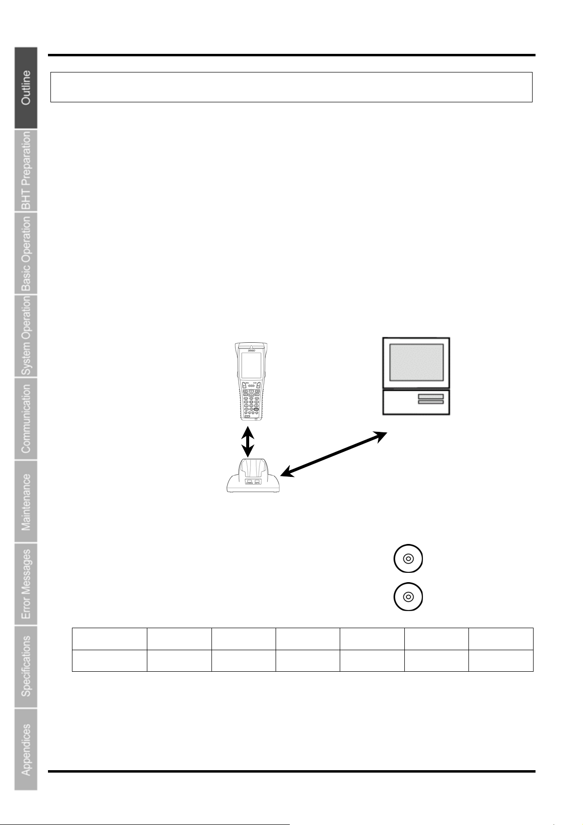
In addition to the BHT, the following hardware and software are required for the barcode data collection
system used by the BHT.
Please note that certain components of the required hardware will differ depending on the type of
communication used.
• Host computer
• CU-800 Series (option): Communication unit
• Software: BHT-BASIC 4.0 Development Pack (Option) and BHT-BASIC 4.0 Transfer Utility (Option)
● : Required for system configuration
IrDA
communication
Host computer BHT CU
● ● ● — ●
BHT
IrDA
communication
CU (option)
Wireless LAN
access point
Host computer
BHT-BASIC 4.0
Development Pack
(Option)
BHT-BASIC 4.0
Transfer Utility
(Option)
Software Ref. Page
Page 32
2
Page 16

Barcode Handy Terminal
Host Computer
Allows you to edit, manage and download user programs and data, as well as downloading system
programs.
Models : PC/AT Compatible
Operating Systems and Optional Application Programs
Operating Systems (OS) Windows 98
BHT-BASIC4.0 Development
Pack
BHT-BASIC4.0 Transfer Utility* √ √ √ √ √
– – √ √ √
Windows NT
3.51/4.0
*This application does not activate any built-in IrDA interface port.
Windows 2000
Professional
Windows XP
32bit edition
CU-800 Series (Option)
Used for communication between the BHT and host computer.
Communication with the BHT is performed by IrDA communication, and communication with the host
computer is performed with an RS-232C, Ethernet or USB interface.
The following three types of CU are available depending on the interface used to communicate with the
host computer.
• CU-801: RS-232C interface
• CU-811: Ethernet
• CU-821: USB interface
Connection Cable (Option or Commercially Available Product)
Used to connect the host computer and CU-800 Series.
Select a cable suited to the CU-800 Series interface being used.
Supported CU-800 Series Cables
• CU801: RS-232C cable (Option)
• CU-811: Ethernet (10BASE-T) cable (commercially available product)
• CU-821: USB cable (Option)
BHT-BASIC 4.0 Development Pack (Option) and BHT-BASIC 4.0 Transfer Utility
Windows Vista
32bit edition
(Option)
Refer to “Software Configuration” on the following page.
3
Page 17
BHT-805B
1.1.2 Software Configuration
This section describes the software used for BHT Series application development and application in
addition to the software used at the BHT unit.
Please note that the above-mentioned software can be downloaded (Certain versions may be for trial
use.) from the QBdirect service discussed at “Customer Registration” on page ii.
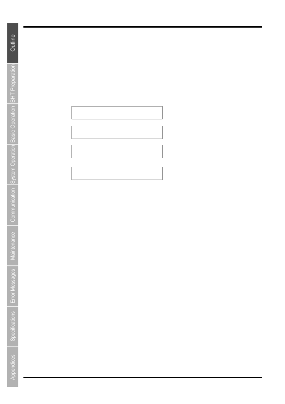
[1] Application Development Procedure
The procedure for BHT Series program development is as follows.
Program creation
Program generation (compiling and linking)
Program download
Program execution and debugging
[2] Software Used for Application
BHT-BASIC Programmer’s Manual for BHT-800 Series
This is an instruction manual used to create handy terminal programs with BHT-BASIC.
BHT-BASIC 4.0 Development Pack (Option)
This is a package containing four software products required for BHT Series application development
and accessories.
The BHT-BASIC 4.0 Development Pack contains the following products.
• BHT-BASIC 4.0 Compiler
Compiles and links a source program written in BHT-BASIC 4.0 to create a user program executable
on the BHT (*.PD4).
• BHT-BASIC4.0 Transfer Utility
Transfers files between the host computer and BHT at the host computer.
YMODEM or BHT-Ir protocol is used for file transfer.
BHT-BASIC 4.0 specification files such as application programs and data files are transferred using
YMODEM protocol.
BHT-BASIC4.0 Transfer Utility (Option)
This is the same BHT-BASIC 4.0 Transfer Utility that comes bundled with the BHT-BASIC 4.0
Development Pack.
4
Page 18
Barcode Handy Terminal
r
[3] Software Used at the BHT Unit
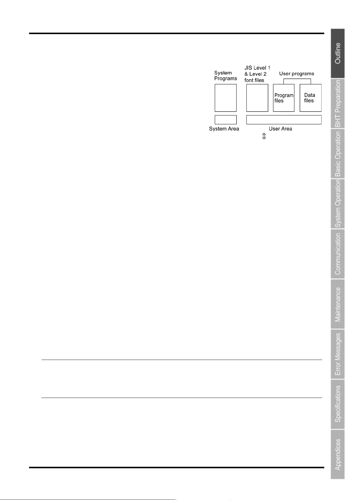
The BHT unit FLASH memory has a system area and
user area, with the system program stored in the
system area and font files and user programs stored in
the user area.
The BHT unit is shipped with the system program and font
files stored in their respective areas.
Application programs (*.PD4) stored in the user area are run by the system program in order to use the
BHT.
It is necessary to download application programs (*.PD4) and data files (product master files etc.) required
to run application programs (*.PD4) to the BHT user area prior to use.
System Program
• Driver
Driver is a set of programs that directly controls the BHT hardware. It can be called up by the
BHT-BASIC Interpreter or System Mode.
• BHT-BASIC Interpreter
This program interprets application program (*.PD4) command language and controls the BHT unit
hardware via drivers.
• System Mode
This program is used to operate files, make system environment settings, and perform various types of
tests.
Refer to “Chapter 4 System Operation” –“4.4 System Mode” for further details.
Font File
These files are required to display JIS 1 and 2 standard Kanji characters at the BHT unit LCD display.
By using font files, the BHT unit is able to display 16 to 40 dot Kanji in application programs (*.PD4).
− Point − If you do not need to display Kanji characters, you may delete these JIS font files. After deletion, the
memory area which was occupied by these files can be used as a user area. For the deleting
procedure, refer to "Chapter 4 System Operation" - "4.1.4 Performing System Initialization"o
"4.5.11 Deleting Font Files (DELETE FILE Menu)."
The names of the font file: FNTFSHG.FN4 (JIS Level 1 and 2 font, 16-dot to 40-dot)
Host computer
User Programs
Application programs and data files are downloaded to the BHT user area and are collectively known
as user programs.
To download a BHT-BASIC 4.0 specification user program to the BHT unit, the BHT-BASIC 4.0
Transfer Utility is required.
5
Page 19
BHT-805B
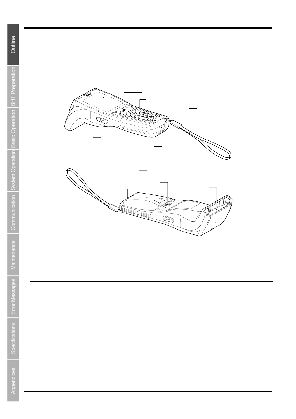
1.2 Component Names and Functions
1.2.1 BHT Front/Rear
(2)
(1)
(5)
(4)
(3)
(6)
(11)
(8)
(9)
No. Name Function and Description
(7)
(10)
(1) LCD (Liquid crystal display) Displays the characters and graphic patterns.
(2) Indicator LED Indicates the barcode read status.
Illuminates in blue when the BHT has successfully read a barcode.
(3)
Trigger switch
(4)
(M3 and M4 Magic keys)
(5) Speaker Emits sound.
(6) IrDA interface port Used to exchange data/programs with the communication unit CU-800 or other BHTs.
(7) Hand strap Wear this strap around your wrist to prevent you from dropping the BHT accidentally.
(8) Battery cover Remove this cover to replace the battery cartridge.
(9) Battery cover lock Use this to lock or unlock the battery cover.
(10) Barcode reading window Align the reading window with barcodes to perform barcode reading.
(11) Charge terminal Place on the CU to charge the BHT.
6
Press when reading a barcode.
The SF and ENT key functions can be assigned to these magic keys by making settings at the
SYSTEM MENU.
Character strings can be assigned at user programs.
* Refer to “Chapter 4 System Operation” for details on how to operate the SYSTEM MENU.
Page 20
(3)
(2)
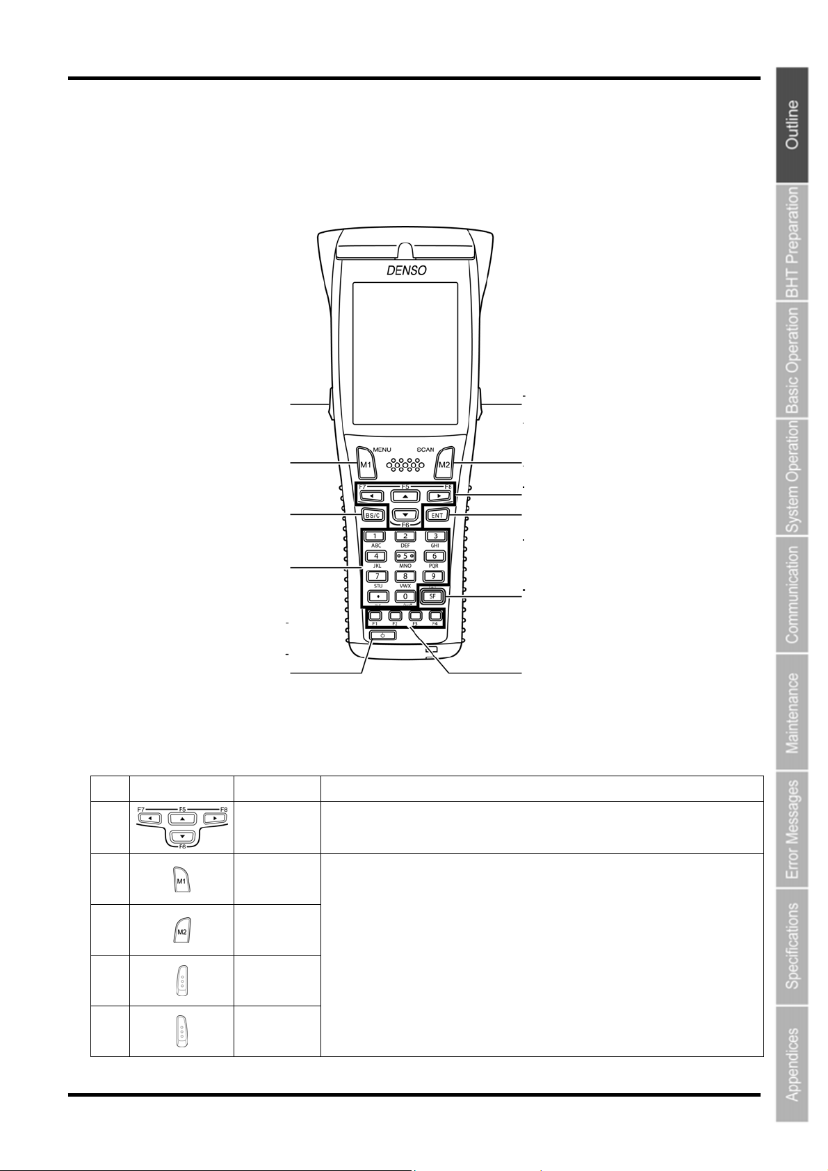
1.2.2 Keypad
The BHT key functions can be set at user programs.
The diagram below shows an example of settings for each key function.
Key Name Function and Description
No.
(4)
(10)
(6)
(9)
Barcode Handy Terminal
(5)
(1)
(7)
(11)
(8)
(1)
(2)
(3)
(4)
(5)
Cursor keys
Magic key
[M1]
Magic key
[M2]
Magic key
[M3]
Magic key
[M4]
Used to move the cursor and select menus.
• Each of the M3 and M4 keys is assigned a trigger switch by default.
• The SF, ENT, Backlight, MENU or C key functions can be assigned with SYSTEM
MENU.
• Character or character strings can also be assigned with the user programs.
• Hold down the M1 key to display the following setting screens when set to the default.
- Volume
- Vibrator
- LCD display brightness
- Power save
7
Page 21
BHT-805B
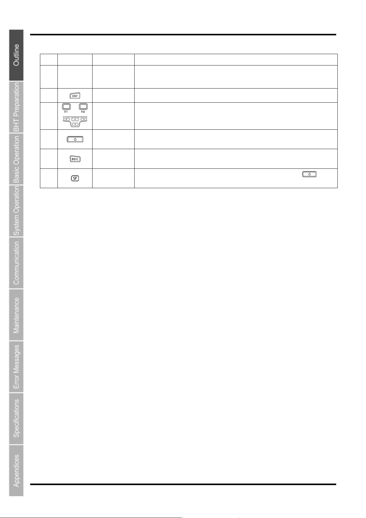
Key Name Function and Description
No.
(6)
(7)
(8)
(9)
(10)
(11)
-
Numerical keys
Enter key
Function keys
Power key Turns ON or OFF.
Backspace/clear
key
Shift key
Used to enter data.
Press to finalize entered data or execute operations.
Used to select functions. *Function key functions are assigned at user programs. Refer to
the “BHT-BASIC Programmer’s Manual (For BHT-800 Series)”.
Deletes the last entered character (backspace). When pressed and held for 1 second or
more, cancels entry and returns the LCD display to the previous screen (clear.)
Used in combination with other keys such as the numerical keys and
special input procedures.
key for
8
Page 22
Barcode Handy Terminal
A
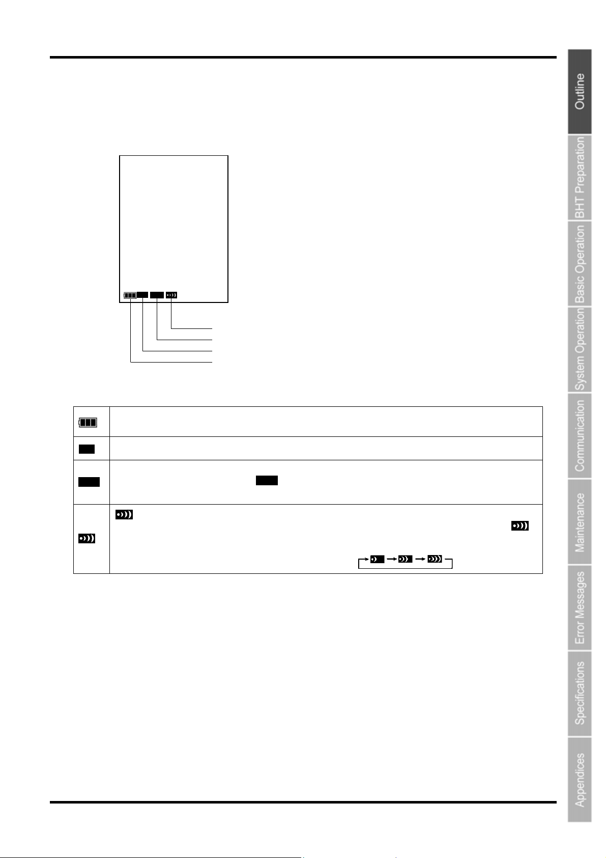
1.2.3 BHT Screen
If the system display is set to ON at the system settings or in the user program, icons display at the bottom of the
screen (default) indicating the key shift status, alphabet entry status, and status of the link with the CU-811.
SF ALP
Link status with CU-811
lphabet entry status
Key shift status
Battery icon
This is the battery icon.
Indicates the current battery power level.
SF
Displays when the SF key is pressed and the keys are in the shift status.
When the SF key is pressed while set to alphabet entry mode at the user program, the entry mode changes from
ALP
“numeric entry” to “alphabet entry” and displays.
Alphabet entry is used when performing FTP settings.
ALP
displays when a link is established with the CU-811.
When an attempt is made to perform communication with the CU-811 when no link has been established, the
icon flashes.
When there is no response from the CU-811, when waiting for the link with the CU-811 to be established, or when
waiting for the link to be disengaged, the icon displays in the order .
9
Page 23

BHT-805B
10
Page 24

805
BHT-
Chapter 2
B
BHT Preparation
This chapter describes inserting and charging the battery cartridge, turning
the BHT power ON and OFF, and use of the hand strap.
2.1 “BHT Preparation” Procedure ·····································································12
2.2 Inserting and Charging the Battery Cartridge ·············································12
2.2.1 Battery Power Level Indicator ········································································18
2.3 Wearing the Hand Strap ·············································································19
2.3.1 Attaching the Hand Strap ··············································································· 19
2.3.2 Holding the BHT ·····························································································19
2.4 Initial Setup ·································································································20
2.5 Turning OFF the Power ··············································································21
2.5.1 Normal Power OFF ························································································21
2.5.2 Turning the Power OFF after Data Back-up ··················································21
2.5.3 Auto Power OFF ····························································································21
2.5.4 If the BHT Is Shut Down Abnormally······························································ 22
2.5.5 If Broken Files Are Found ··············································································24
Page 25
BHT-805B
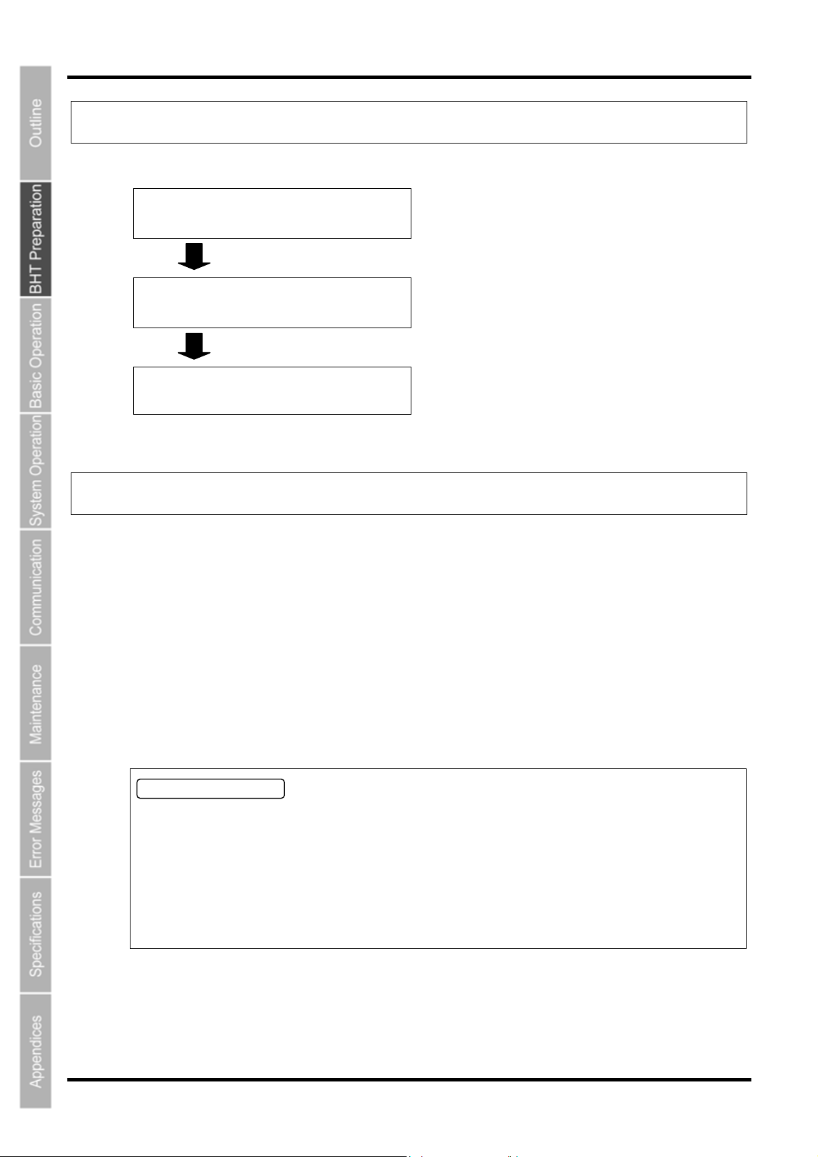
2.1 “BHT Preparation” Procedure
Follow the steps below to prepare the BHT for use.
2.2 Inserting and Charging the Battery
Cartridge(Page 14)
2.3 Wearing the Hand Strap
(Page 21)
2.4 Initial Setup
(Page 22)
First insert and charge the battery cartridge.
Wear the hand strap at your wrist to prevent the BHT
from being dropped.
Set the calendar clock when the power is turned ON for
the first time.
2.2 Inserting and Charging the Battery Cartridge
The battery cartridge is not charged when purchased and should therefore be charged prior to use.
The chargers that can be use with the BHT are the communication units (CU-801, CU-811 and CU-821) and battery
chargers (CH-201A, CH-851, CH-704 and CH-854).
* The CH-201A and CH-704 are chargers to separately charge the battery cartridge on its own, while the
CH-851 and CH-854 are stationary model (same type as CU (communication unit)) for directly charging
the battery cartridge placed in the BHT.
The charging time is approximately 3 hours.
• The charging time is approximately 7 hours using the CU-821 with power supplied via the USB port.
• This time will be reduced for a battery cartridge with low discharge capacity.
Charging Precautions
• Do not touch any terminal of BHT, battery, or charger by hand or stain them. Doing so could result
in a contact failure or prevent charging.
• Never charge the battery near fire or in a high-temperature environment.
High-temperatures may activate the charger’s protective device, preventing from charging, and lead
to protective device damage, overheating, blowout or combustion.
• Terminate charging if not completed even after the specified time has elapsed.
• Do not use battery cartridges other than that specified by DENSO WAVE.
12
Page 26
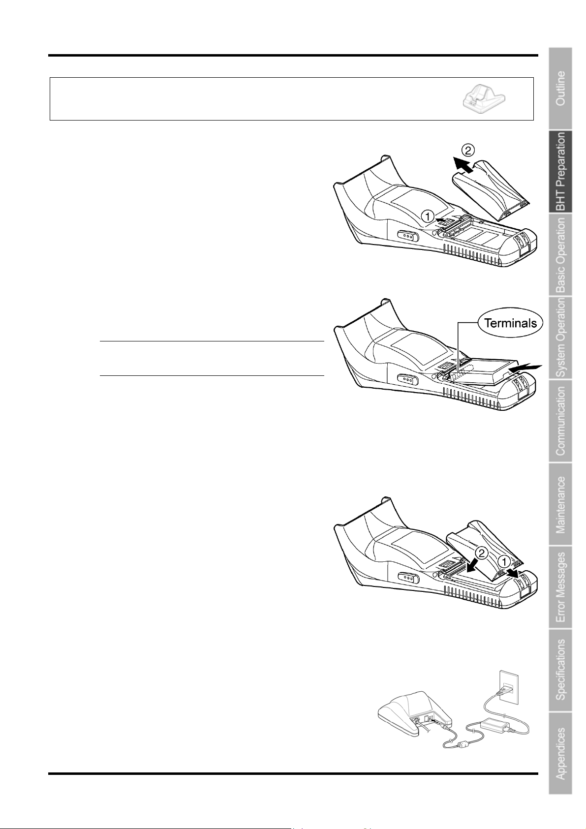
Charging with the communication unit (CU-801, CU-811 and CU-821)
or battery charger (CH-851 and CH-854)
1. Slide the battery cover lock (1) in the direction
indicated by the arrow and remove the battery
cover (2).
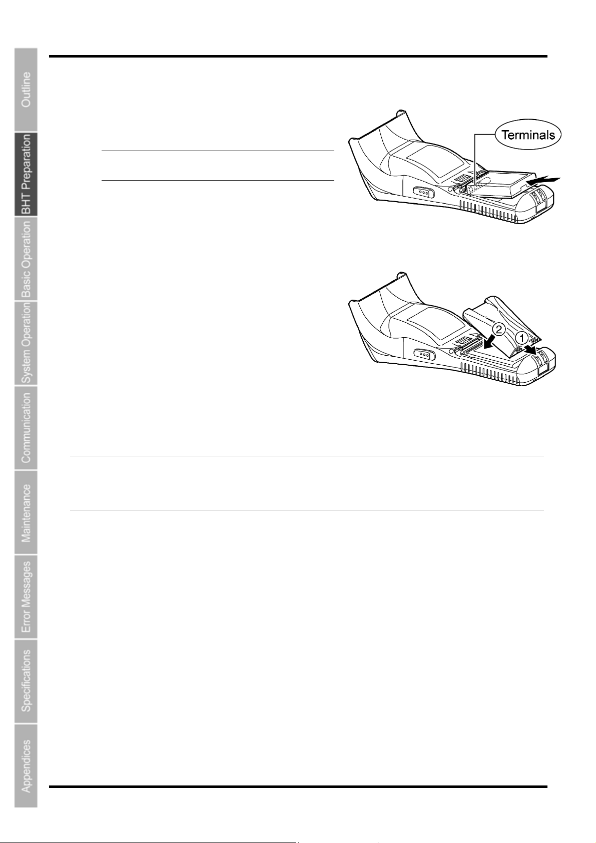
2. Insert a new battery cartridge in the direction
indicated by the arrow. Make sure that the battery
cartridge is in the right orientation.
Barcode Handy Terminal
− Point − Do not use battery cartridges other than
those specified by DENSO WAVE.
3. Insert the battery cover tab (1), and then close the
battery cover (2). The battery cover is now locked
in position.
4. Connect the dedicated AC adapter to the DC input connector on the charger and plug the
adapter into the wall socket.
The charger Power LED (green) turns ON.
13
Page 27
BHT-805B
r
r
BHT-805B
− Note − Power for the CU-821 can be obtained from a USB connection port (host computer or hub),
however, charging is not possible while the host computer is in suspend mode. Charging is
resumed when suspend mode is exited. This can be avoided using a dedicated AC adapter to
supply power. Suspend mode is a power saving function used to temporarily put the computer on
standby when not in use.
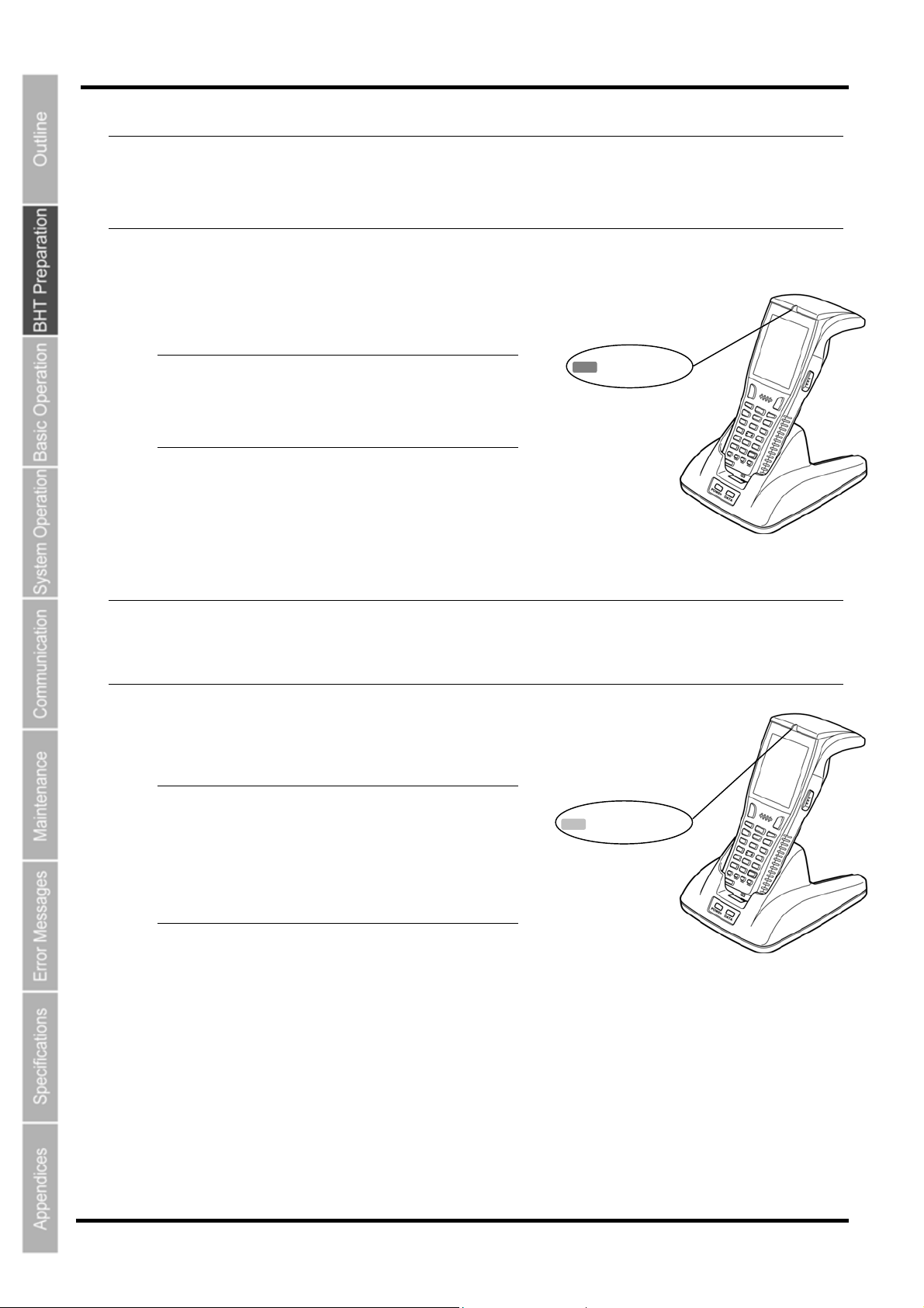
5. Place the BHT on the charger.
The indicator LED illuminates in red and charging begins.
− Point − After placing the BHT on the charge
*When the BHT is set on the charger, the LCD screen will
momentarily turn gray.
− Note − The BHT is equipped with a back-up battery used to back-up the internal memory and calendar
clock. The internal back-up battery is charged first when charging is commenced.
Do not remove the BHT from the charger for at least 10 minutes when using the BHT for the first
time or when using after long periods of time.
when using the BHT for the first time or
when left unused for long periods of time,
do not remove from the charger fo
approximately 10 minutes.
Red LED ON
6. The BHT indicator LED will change to green
when charging is complete.
− Point − Charging takes approx
Charging takes approx
when using t
supplied via th
An only slightly discharged battery
cartridge should take this time to
become fully charged.
he CU-821 with power
e USB port.
imately 3 hours.
imately 7 hours
Green LED ON
14
14
Page 28
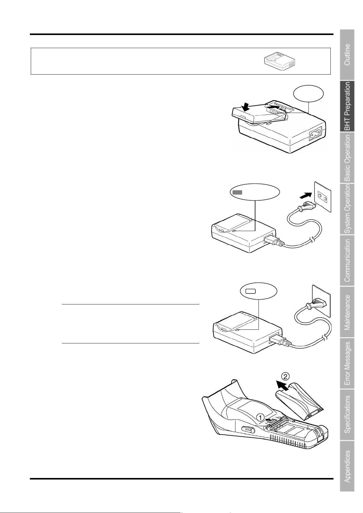
Ch arging w h the battery charger (CH-201A and CH-704) it
Barcode Handy Terminal
1. Check the battery cartridge terminals and insert the
artridge.
c
2. Connect the power cable to the CH-201A and
connect the plug to a
(230 V AC).
The LED will turn red when charging is commenced.
commercial AC power source
Terminal
Red LED ON
3. The LED will turn OFF when charging is comp
− Point − Charging takes approximately 3
hours.
An only slightly discharged battery
cartridge should take this time to
become fully charged.
4. Slide the battery cover lock (1) in the direction
indicated by the arrow and remove the battery
cover (2).
lete.
OFF
15
Page 29
BHT-805B
5. Insert a new battery cartridge in the direction
indicated by the arrow. Make sure that the battery is
in right orientation.
− Point − Do not use battery cartridges other than
those specified by DENSO WAVE.
6. Insert the battery cover tab (1), and then close the
battery cover (2). The battery cover is now locked in
osition.
p
− Note − The BHT is equipped with a back-up battery use
clock. The internal back-up battery is charged first mmen
Do not remove the BHT from the charger for at least 10 minutes when using the BHT for the first
time or when using after long periods of time.
d to back-up the internal memory and calendar
when charging is co ced.
16
Page 30
Barcode Handy Terminal
r
f
r
r
r
f
Mishandling of the charger may result in charger overheating, smoke generation, blowout o
combustion. Please read the following items prior to use.
Never disassemble or modify the battery cartridg
Never connect the battery cartridge (+) and (-) t
wire.
Never carry or store the battery cartridge together with metallic necklaces, hairpins and so on.
e ply heat.
N ver expose the battery cartridge to fire or ap
Never use or leave the battery cartridge in the vicinity of high-temperature locations (60° C o
higher) such as a fire or stove.
Never place the battery cartridge into or soak it in water or seawater.
Never charge the battery cartridge in the vicinity of fire or under a scorching sun.
Never hammer nails into the battery cartridge, hit it with a hammer, or trample on it.
Never apply strong impact to or throw the battery cartridge.
Never use significantly damaged or deformed battery cartridges.
Never apply solder directly to the battery cartrid
If battery fluid leaked from the battery cartridge g
skin, wash thoroughly with clean water such as tap water without rubbing, and obtain medical
treatment immediately. Failure to do so will result in eye or skin injuries.
Mishandling of the charger may result in charger overheating, smoke generation, blowout o
combustion. Please read the following item prior to use.
Terminate charging if not completed even after the specified time has elapsed.
e.
erminals with a metal object such as a piece o
ge.
ets into the eyes or comes into contact with the
− Note − The BHT is equipped with a back-up battery used to back-up the internal memory and calendar
clock when the battery cartridge is removed or the battery voltage falls below the stipulated
level.
It is therefore necessary to charge the internal back-up battery when using the BHT for the first
time or when left unused for long periods of time.
The back-up battery is charged automatically when a fully-charged battery cartridge is loaded.
To ensure that the back-up battery is fully charged, do not remove the battery cartridge for at
least 10 minutes when using the BHT for the first time or when using after long
If you leave the BHT without a battery cartridge loaded for a long time, the memory contents will
no longer be backed up so that the me
ssage "Contact your administrator. Note the erro
periods of time.
number. (XXXX)" or "Set the current date and time." may appear on the LCD.
Refer to “Chapter 6 Maintenance” – “6.3 Using the BHT after Long Periods” for details o
handling the BHT after long periods of time.
Avoid storing the battery cartridge in high-temperature locations. The battery capacity may
decrease.
Do not touch the BHT, battery, or charger terminals by hand or stain them. Doing so may result
in a BHT operation defect or battery cartridge charging failure. It is recommended that dirt on
the battery cartridge terminals or BHT battery terminals be periodically wiped with a soft, dry
cloth.
17
Page 31
BHT-805B
2.2.1 Batt
ery Power Level Indicator
Confir
The batte
screen.
The bat
The bat
.
rtridge.
Confir
The batte
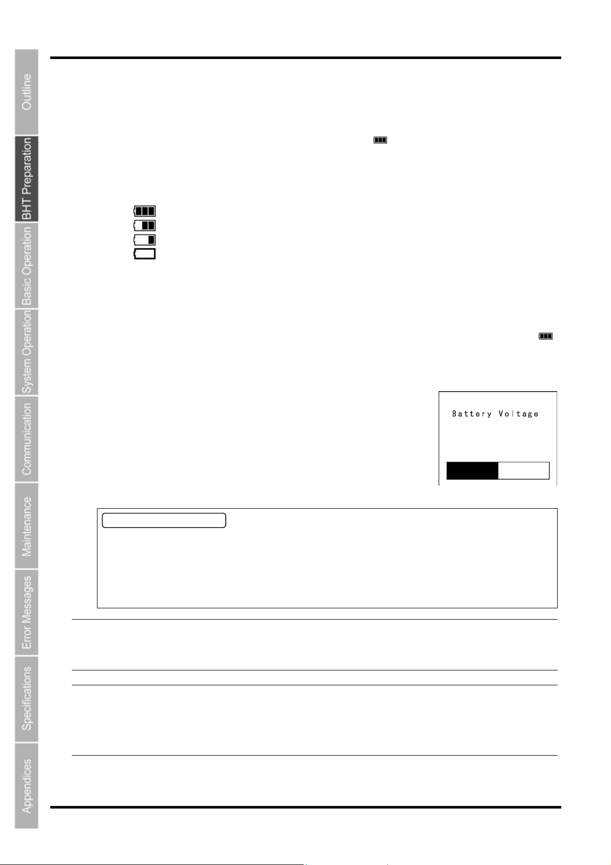
The "Battery Voltage" screen displays the battery power level in more detail than the battery icon
displaye
Display
ming at the Power Level Icon
ry power level can be confirmed at the battery icon ( ) displayed in the bottom left of the LCD
tery power is indicated in four levels.
tery power level indicator tells you when to charge the battery cartridge.
:Sufficient battery power remains.
:The battery power is partially depleted. Making early charge is recommended
:The battery power is almost depleted. Charge the battery immediately.
:The battery power is totally depleted.
Charge immediately or replace with a fully charged battery ca
ming at the “Battery Voltage” Screen
ry power level can also be confirmed at the "Battery Voltage" screen.
( )
d in the LCD screen.
the "Battery Voltage" screen using the following procedure.
2. Hold down the SF key and press the ENT key.
Ba
The " ttery Voltage" screen displays while the keys are pressed.
About the Battery Level
• The b
• The b
• Ensure
− Point − If the BHT is placed in the alphanumeric entry system in user programs, the combination of the
− TIP − In user programs, you may select the key to be used for displaying the battery voltage level
attery power level indicator does not accurately reflect the battery residual power and should
only be
occur
used as a guideline.
attery power level will fluctuate due to BHT operation, and therefore disparities may
between the actual battery voltage and the display indicator.
to charge the battery as soon as possible before the battery power is depleted.
SF and ENT keys cannot be used for displaying the battery voltage level. This is because in the
alphanumeric entry system the SF key and ENT keys are used for switching between the numeric
and alphabet entry modes.
(instead of the default: combination of SF and ENT keys).
The displayed battery level shows the terminal voltage of the battery, not how much power is left.
The actual voltage level varies depending upon the operation of the BHT, so the displayed level
also may vary.
18
Page 32
2 .3 Wearing the Hand Strap
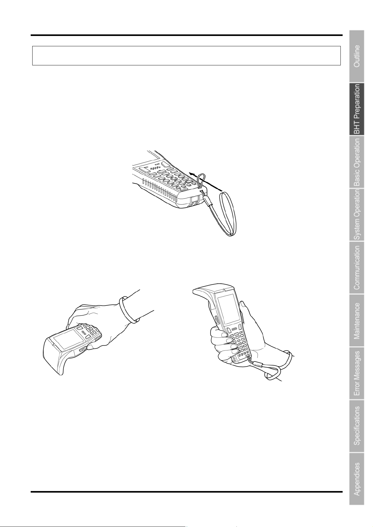
Always put
the hand strap around your wrist to prevent the BHT from being accidentally dropped during the operation.
Barcode Handy Terminal
2.3.1
Attaching the Hand Strap
Attach the hand strap to the BHT as shown below.
2.3.2 Holding the BHT
Wear the hand strap at your wrist and hold the BHT as shown below.
or
19
Page 33
BHT-805B
2.4 Initial Setup
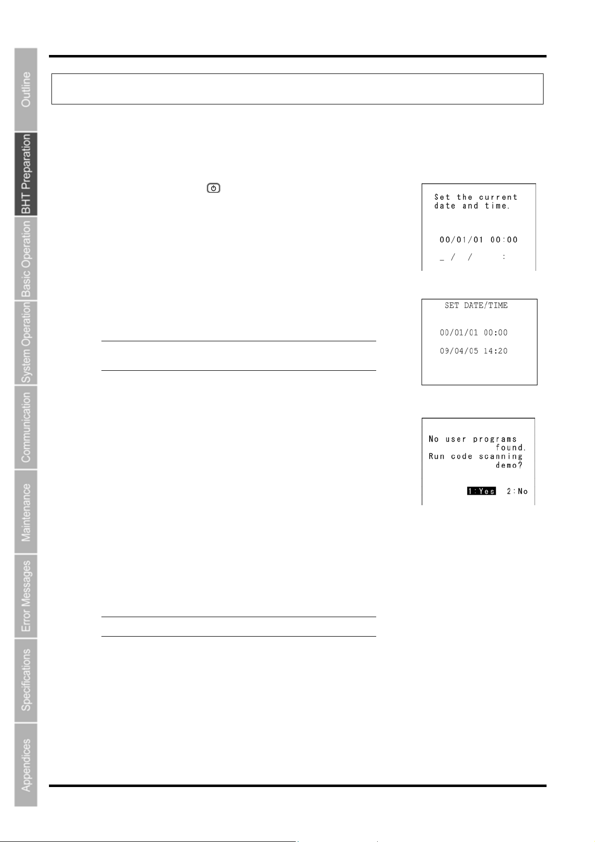
Turn ON the power after inserting the fully charged battery cartridge into the BHT.
The date and time are not set at the time of purchase. You are required to set the date and time when turning ON the
power for the first time.
1. Press the Power key ( ) to turn ON the BHT.
The screen to the right displays.
2. Enter the date and time using the numeric keys.
[Ex.] : April 5, 2009, 14:20
− Point − Enter the last two digits for the year, and enter the
time in 24-hour clock format.
3
. Press the ENT key to set the date and time.
The screen to the right displays when the date and time are set.
4. Press numeric key 1 and the ENT key. Then, select [1:Yes].
A scanning demo commences.
The scanning demo is a program that allows barcodes to be scanned without a user program. Press the
trigger switch to enable barcode scanning.
Refer to "Chapter 3 Basic Operation" – “3.1 Scanning Barcodes” and scan a barcode .
− Point − The power turns OFF by selecting [2:No].
20
Page 34
Barcode Handy Terminal
f
2.5 Turning OFF the Power
You can turn off the BHT in one of the following three methods.
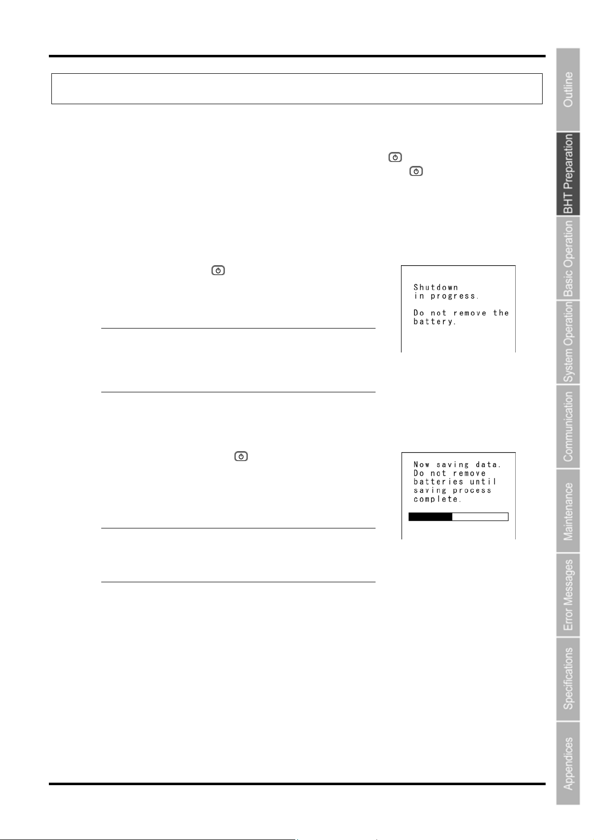
Normal power OFF → Press the Power key (
Turning the power OFF after data back-up → Hold down the Power key (
A turns OFF itself w
uto power OFF → The power hen the BHT is not used for
the specified pe
riod of time set at the user program.
2.5.1 Normal Power OFF
).
) for at least 3 seconds.
1. Press the Power key (
The BHT turns OFF after the message on the screen g
right displays.
− Point − Do not remove the battery cartridge while the
2. ata Back-up
5.2 Turning the Power OFF after D
1. old down the Power key (
H ) for at least 3 seconds.
he message shown on the appears and data back-up is
T
ommenced.
c
The pow
− Point − Do not remove the battery cartridge while the
message on the right is displayed.
Otherwise, a message reques
administrator may appear when the power is turned
ON next time.
er turns OFF automatically when the back-up is complete.
message on the rig
The back-up process may take several tens o
seconds depending on the amount of data.
).
iven to the
ting you to contact the
ht is displayed.
2.5.3 Auto Power OFF
The po
p
This is set to 3 minutes at default when the BHT is shipped from the factory.
* Refer to “BHT-800 Programmer’s Manual” for details of auto power OFF.
wer turns OFF itself when the BHT is not used for the specified period of time set at the user
rogram.
21
Page 35
BHT-805B
2.5.4 If the BHT Is Shut Down Abnormally
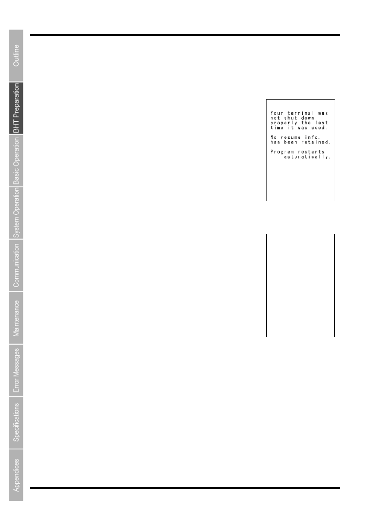
If the BHT is shut down abnormally* and is left without a battery cartridge or with a discharged battery
cartridge loaded, then unsaved data may be lost.
(*"Normally shut down" refers to "2.5 Turning OFF the Power.")
1. The right you load a charged battery
message will appear when
cartridge and turn the BHT on.
2. Next, the tes right. In
some instan y take up to 20 to 30 seconds. When
ting message will appear as in the screen to the
ces testing ma
complete, the system starts.
Testing
22
Page 36
Barcode Handy Terminal
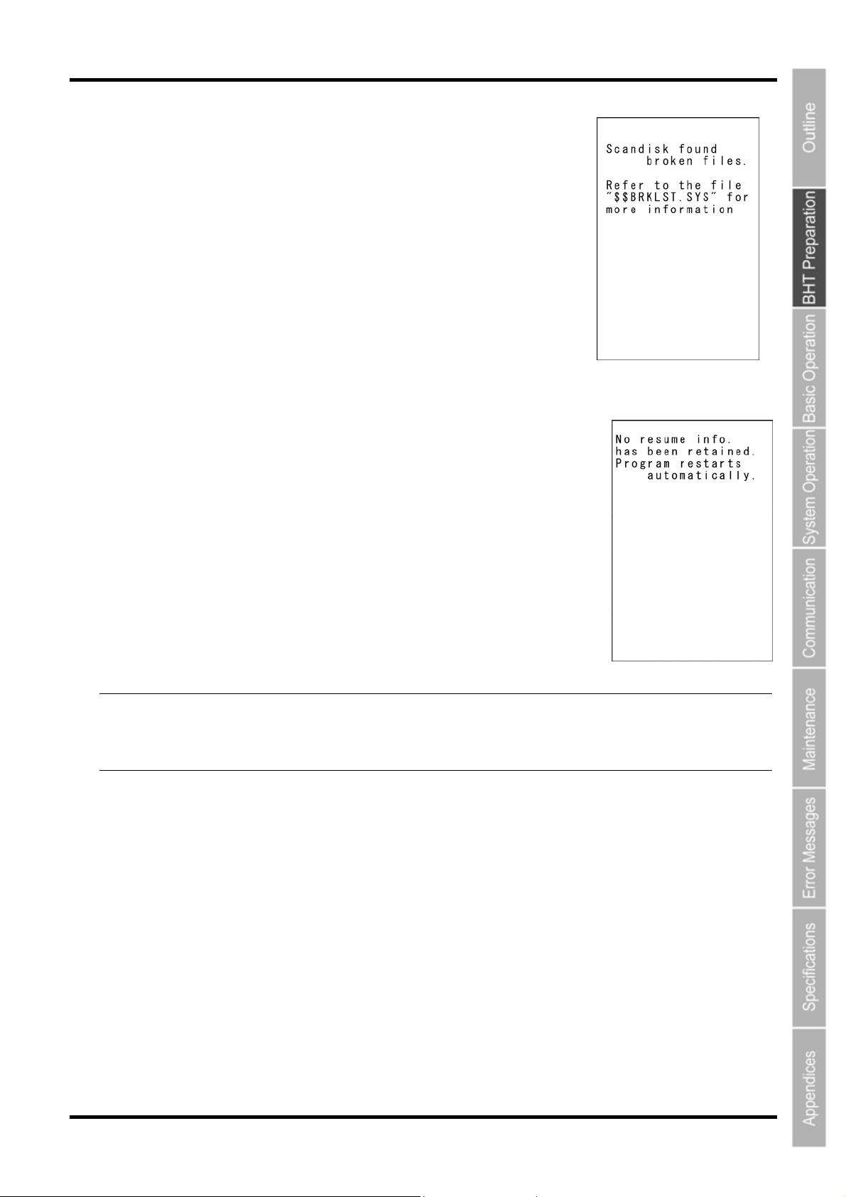
If Scandisk finds a broken file(s), the right screen will appear.
(As long as a broken file exits, the screen displays every time the BHT
System is started up.)
(Refer to “About “$$BRKLST.SYS” on the following page.)
candisk when the resume function is enabled
S
Scandisk runs when the resume function is enabled, the screen given right
If
ay appear.
m
he BHT displays the screen for three seconds and then automatically runs
T
the execution program from the beginning.
(The screen may also appear when the calendar clock built in the BHT stops,
even without running Scandisk.)
− Point − The resume function is used to return the display to the status (screen) where the power was last
turned OFF when the power is next turned ON.
Resume function settings are made at the “SET SYSTEM” menu. Refer to “Chapter 4 System
Operation” - “4.5.5 System Environment Settings (SET SYSTEM Menu)” for further details.
23
Page 37

BHT-805B
About “$$BRKLST.SYS”
If Scandisk finds a broken file(s), it will automatically create the "$$BRKLST.
o check the contents of the file, upload the file in System Mode to th
T
4 System Operation" – “4.5.3 Uploading Files (UPLOAD ME
ontents of the “$$BRKLST.SYS” file
C
ecords (1) File name
R
x.]
[E
SAMPLE1.DAT + 01000-01050
SAMPLE1.DAT + 01200-01250
SAMPLE1.DAT + 01600-01650
SAMPLE2.DA
AMPLE3.DAT * 00100-00150
S
(1)
(2) Error factor + (Broken since the BHT has not been turned off normally)
* (Broken due to any other causes)
(3) Broken records e.g. 01000-01200 (Data in records numbered 1000 to 1200 is lost)
T * 00250-00275
↑
↑
(2)
↑
(3)
If more than one se
same file, they will
records in the "$$BRKLST.SYS."
NU).")
quence of records is broken in a
be written into the subsequent
e host computer. (Refer to “Chapter
SYS" file.
2.5.5 If Broken Files Are Found
ven broken files can be uploaded, so upload them to the host computer according to your needs.
E
fter uploading,
A
Delete those broken files.
•
(Refer to “Chapter 4 System Operation" – “4.5.10 Deleting Program/Data Files (DELETE FILE
MENU).")
Dow
nload valid files having the same names as the broken ones.
•
e
fer to “Chapter 4 System Operation" – “4.5.2 Downloading Files (DOWNLOAD MENU).") (R
24
Page 38

805
BHT-
Chapter 3
B
Basic Operation
This chapter describes basic operations such as barcode reading, numerical data
entry and item selection using the BHT, basic changes to settings, and BHT data
transmission.
3.1 Reading Barcodes ····················································································26
3.2 Numeric Data Entry···················································································28
3.3 Task Selection ··························································································28
3.4 Changing the Default Settings ··································································29
3.4.1 Procedure·······································································································29
3.5 Transmitting Data······················································································31
3.5.1 IrDA Communication ······················································································32
Page 39
BHT-805B
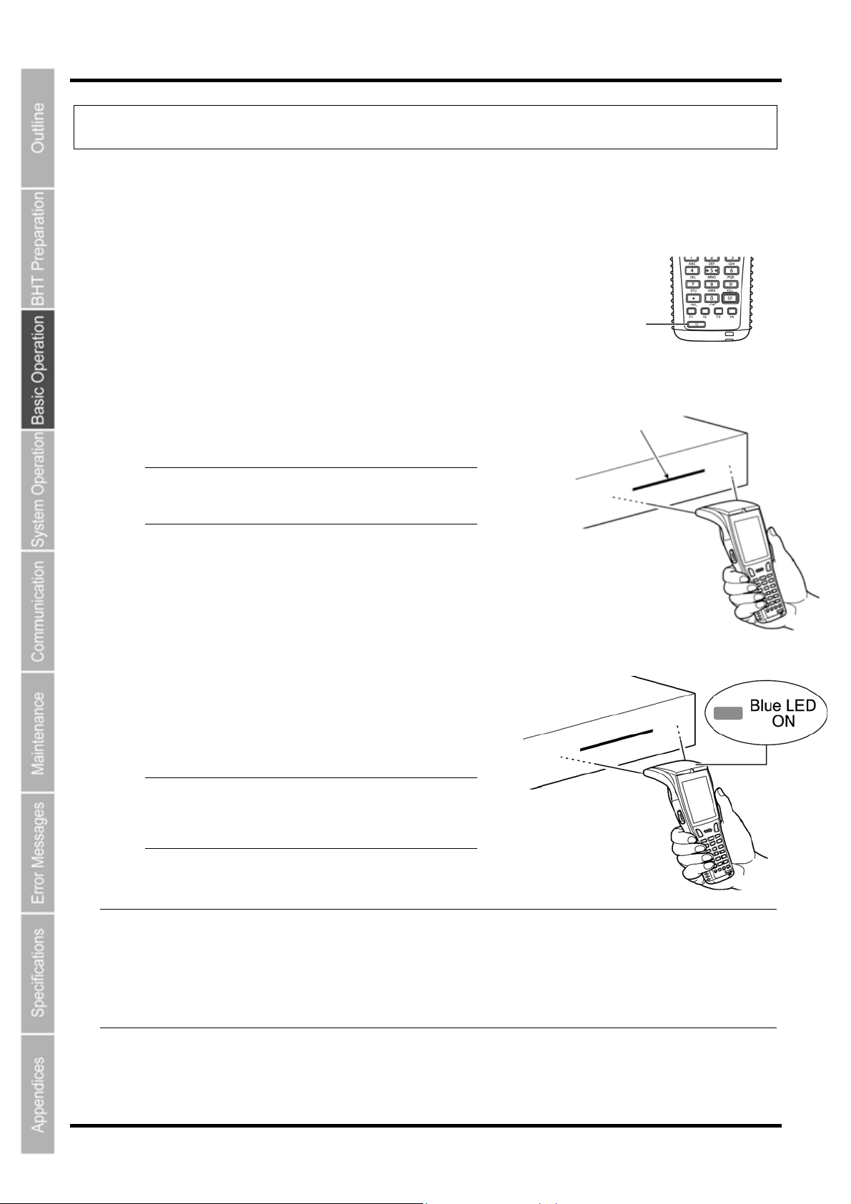
3.1 Reading Barcodes
Follow the procedure below to read barcodes.
1. Turn the BHT power ON.
Power key
2. Press the trigger switch.
The BHT emits a light for reading.
− Point − The trigger switch is assigned to magic
keys M3 and M4 when shipped from the
factory.
3. Hold the BHT close to the barcode within the reach of
light.
When the BHT has read the barcode successfully, the
indicator LED will illuminate in blue.
− Point − The barcode reading method may differ
depending on the application. Select the
most appropriate option in accordance
with the User’s Manual.
Light
26
− Note − If required, clean dirty labels before reading.
It may not be possible to perform reading in direct sunlight.
If the barcode is on a curved surface, perform reading in the center of the light for reading
emission range.
If the barcode reading window is pulled away from the barcode, the readable barcode range will
become narrower than that of the light emission.
Page 40
Barcode Handy Terminal
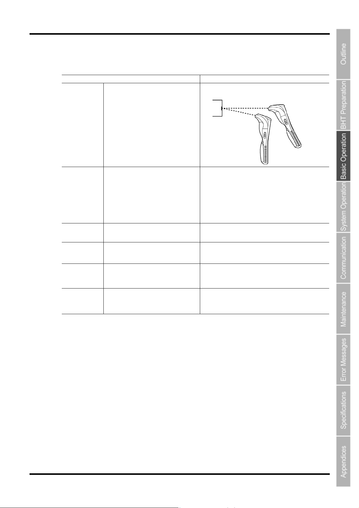
When unable to successfully read barcodes…
Cause Countermeasure
Change the BHT reading angle and try again.
Move the BHT slowly away from the barcode and try again.
Bar code reading is possible from a maximum distance* of 62
cm.
* Under the following conditions:
• Ambient illuminance: 500Lux(fluorescent lamp)
• ITF conforming to the UPC Shipping Container Code
• PCS value: 0.9 or more
• Minimum narrow bar width: 1.2 mm min.
Specular
reflection
Distance from
barcode
When the light is focused on the printed
surface of the barcode from directly above,
the BHT may not read the barcode due to
specular reflection.
The barcode may not be read if it is too close
to or too far from the BHT reading window,
even when the barcode is within the read
area.
Barcode surface
curvature
Barcode surface
dirt
Barcode reading
window dirt
Direct sunlight,
ambient light
The barcode may not be read if its surface
is extremely curved.
The barcode may not be read surface is
dirty.
The barcode may not be read if the
barcode reading window is dirty.
Barcode reading may be adversely
affected by direct sunlight or the
brightness of the surrounding light.
Read the barcode at the center of the barcode reading
window.
Wipe the dirt from the barcode and try again.
Blow any dust away with an airbrush, and then gently
wipe the reading window with a cotton swab or similar soft
object.
Read the barcode away from direct sunlight. Adjust the
brightness of the surrounding light when reading indoors.
27
Page 41
BHT-805B
3.2 Numeric Data Entry
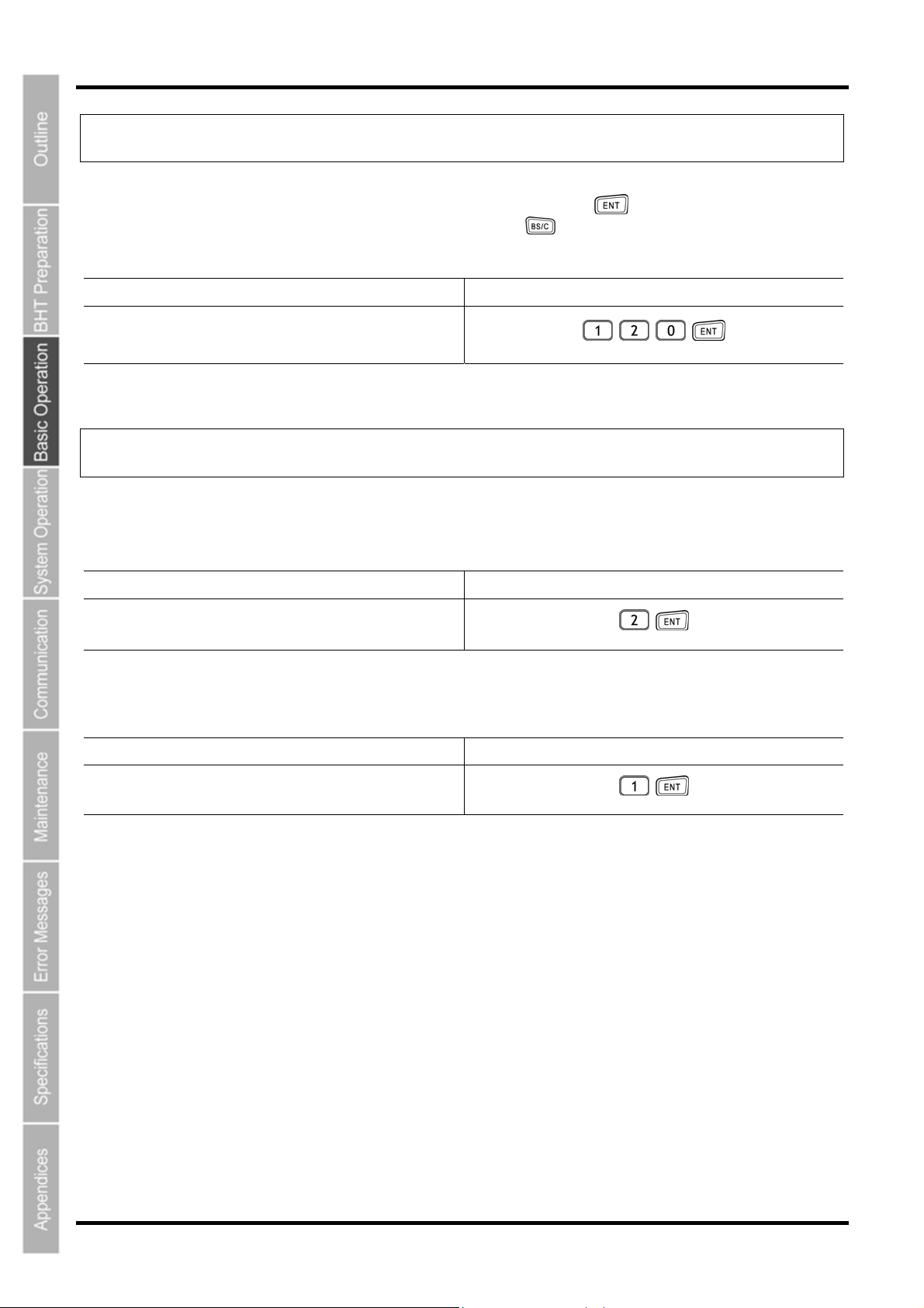
Enter numeric data such as product volume with the numeric keys and Enter ( ) key.
If numeric data is entered incorrectly, use the backspace/clear key ( ) to delete the data and then reenter with the
numeric keys.
When Entering “120” Key Operation
Press numeric keys 1, 2, and 0 followed by the Enter
key.
3.3 Task Selection
If a selection item "such as “1:XXX 2:XXX” with numeric values displays, enter the values with the numeric entry
keys and then press the Enter key.
When Selecting Task 2:XXX Key Operation
Press numeric key 2 followed by the Enter key.
If a YES/NO selection screen such as “1:YES 2:NO” displays, press numeric key [1] to select “YES”, and [2] to
select “NO”.
When Selecting “1:YES” Key Operation
Press numeric key 1 followed by the Enter key.
28
Page 42
Barcode Handy Terminal
3.4 Changing the Default Settings
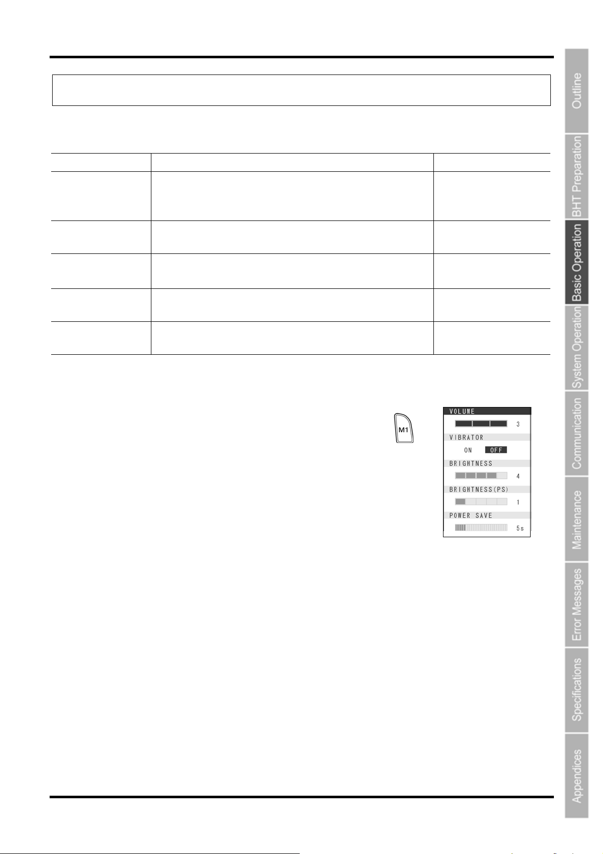
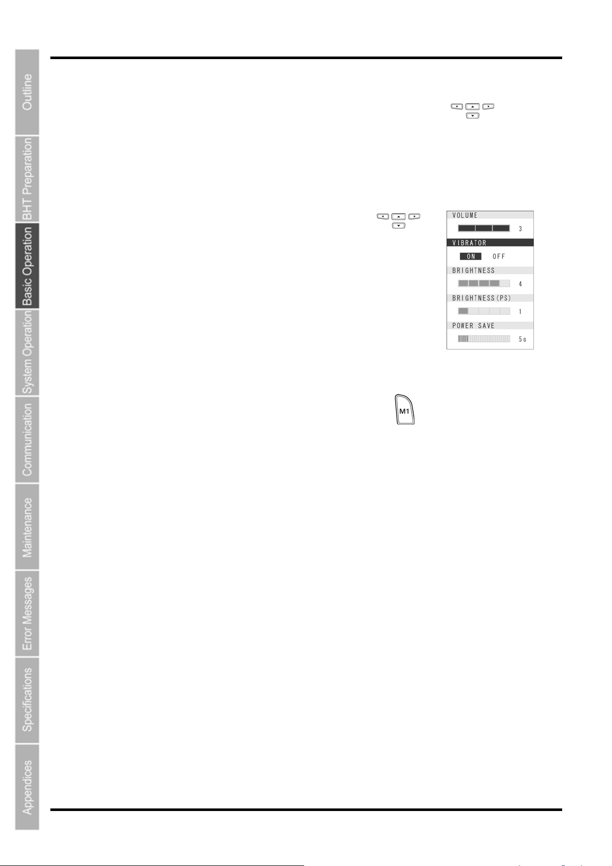
The volume, vibrator, LCD display brightness and power save settings can be changed at the MENU screen.
Item Details Setting
Used to set the volume of the speaker that notifies the user
VOLUME
when barcode reading is complete.
The volume can be adjusted in 4 levels: Hi, Lo, Mid and Mute.
Mute→Lo→Mid→Hi
VIBRATOR
BRIGHTNESS
BRIGHTNESS(PS)
POWER SAVE
Used to turn ON/OFF the vibrator that notifies the user when
barcode reading is complete.
Used to set the backlight brightness of the LCD display.
The brightness can be adjusted in 5 levels.
Used to set the backlight brightness of the LCD display during
power save mode. The brightness can be adjusted in 6 levels.
Used to set the time until the LCD display backlight is dimmed
when not in use in order to save power.
3.4.1 Procedure
1. Hold down magic key M1 for at least 1 second.
The MENU screen displays
ON, OFF
Levels 1 to 5
Levels 0 to 5
1-second units
(max. 30 seconds)
29
Page 43
BHT-805B
2. Use the [▲] and [▼] cursor keys to select the item to be changed.
The selected item is highlighted.
3. Use the [◄] and [►] cursor keys to select the setting.
4. Press any of the following keys to exit the settings screen.
● M1 key long press
● Backspace/clear key
● Enter key
The settings screen is exited.
30
Page 44
Barcode Handy Terminal
3.5 Transmitting Data
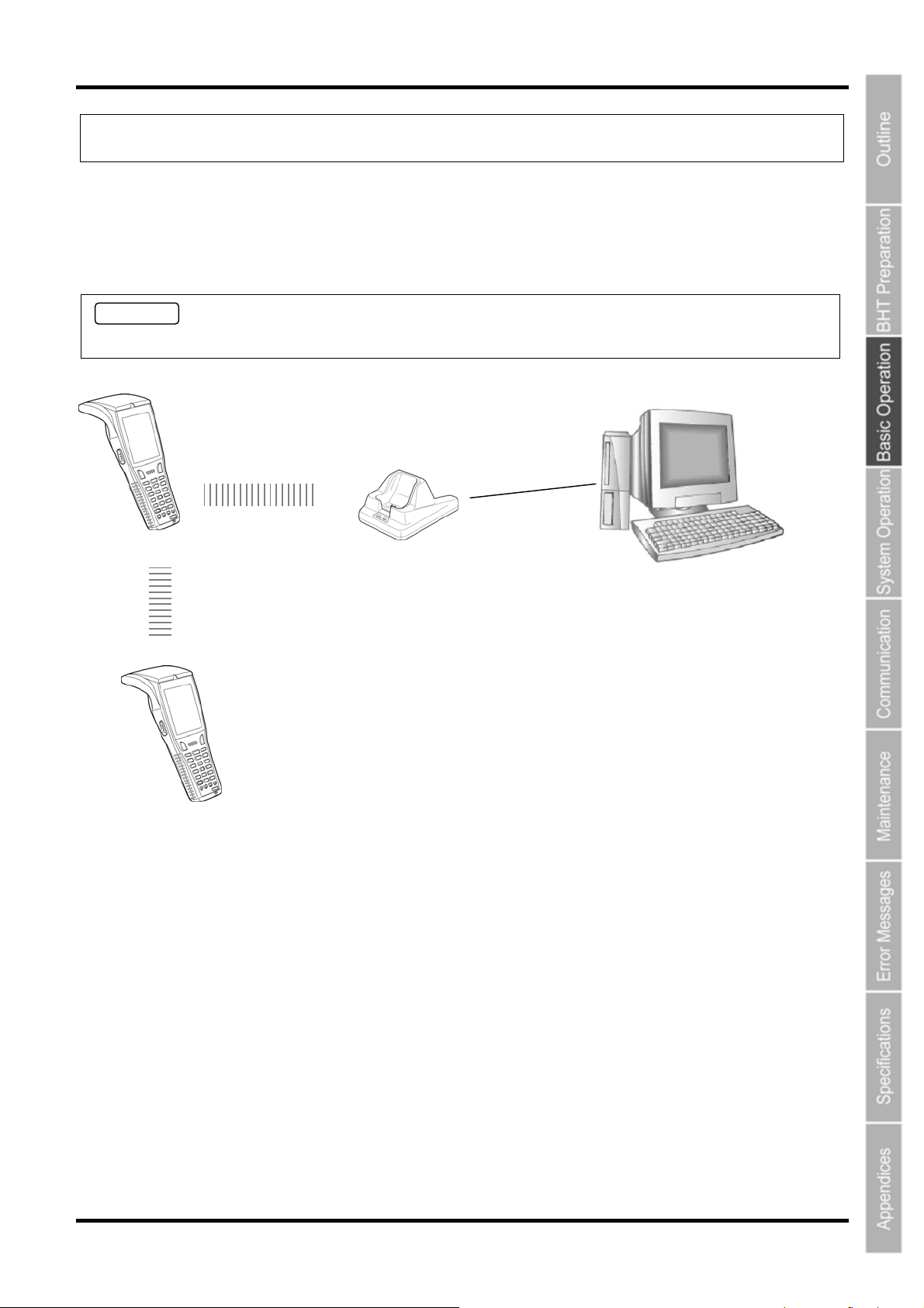
Data gathered by the BHT can be transmitted to the host computer by IrDA communication.
The data transmission method and BHT setting method will differ depending on the system used, and therefore the
system administrator should be contacted for details of operation.
Request
Data gathered by the BHT should be promptly uploaded to the host computer.
IrDA
communication
IrDA
communication
CU-801
CU-821
CU-811
CU-801: RS232C
CU-821: USB
CU-811: Ethernet
Host computer
31
Page 45
BHT-805B
3.5.1 IrDA Communication
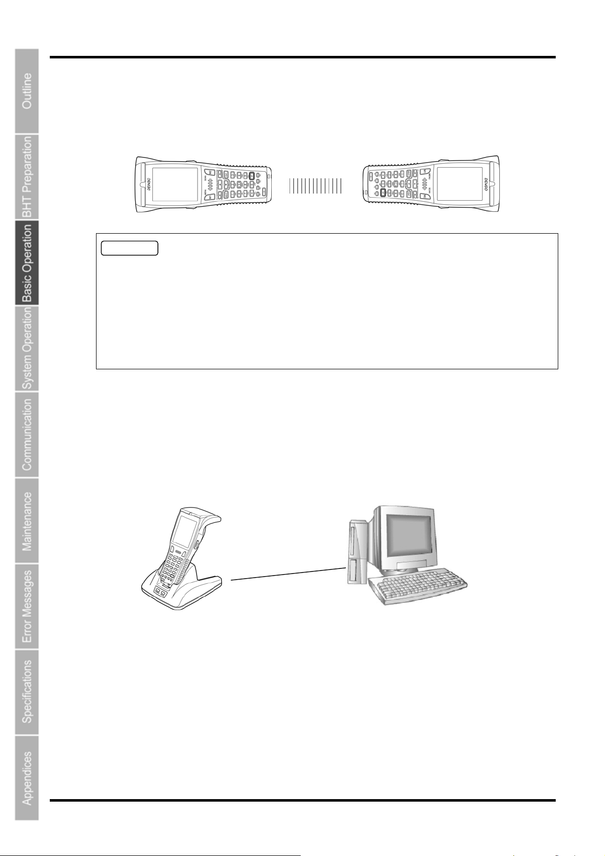
When performing data communication between BHT units
Point the BHT IrDA communication ports toward each other and perform communication.
Requests
• Make sure that the light path between the BHT and any target stations is not obstructed.
• Perform communication within the effective infrared emission range (15 cm).
• Do not operate remote control units for televisions and so forth in the vicinity of IrDA communication.
This may result in comunication failure.
• Perform communication in locations where the BHT units will not be exposed to light interference from
sources such as intense ambient lighting (inverter-driven fluorescent lighting, in particular) or direct
sunlight. This may result in comunication failure.
When performing data communication with the host computer
Place the BHT on the communication unit (CU-801, CU-811 or CU-821) and transmit data.
In case of using the CU-601 or CU-621, the BHT-BASIC 4.0 Development Pack (Option) and BHT-BASIC
4.0 Transfer Utility (Option) software is required.
In case of using the CU-611, FTP communication environment is required.
CU-801: RS232C
CU-811: Ethernet
CU-821: USB
32
Page 46

805
r
BHT-
Chapter 4
B
System Operation
This chapter describes how to initialize and update the system, start up a use
program, and operate System Mode.
4.1 Initializing the BHT System·········································································34
4.1.1
Selecting the Memory Area to be Initialized···················································35
4.1.2 Selecting the Message Version (English or Japanese) ·································36
4.1.3 Confirming the Memory Area Selected for Initialization································· 36
4.1.4 Performing System Initialization·····································································37
4.2 Updating the System ··················································································38
4.2.1 Updating the BHT System··············································································38
4.2.2 CU-811 System Update ·················································································39
4.3 Executing User Programs···········································································40
4.3.1 Executing from the SYSTEM MENU “EXECUTE PROGRAM”····················· 40
4.3.2 Automatically Executing the Program Set at the SYSTEM
MENU when Turning the Power ON
4.3.3 Executing the First Registered Program by Turning the Power ON
(BHT System Directory Management Program Function)······························40
4.3.4 Executing by Wake-up ···················································································42
4.3.5 Executing by Remote Wake-up······································································42
4.4 System Mode······························································································43
4.4.1 Starting Up System Mode ··············································································43
4.4.2 System Mode Basic Operation ······································································44
4.4.3 SYSTEM MENU Configuration ······································································46
4.5 SYSTEM MENU ·························································································50
4.5.1 Executing Setup (SETUP Menu) ···································································50
4.5.2 Executing User Programs (EXECUTE PROGRAM Menu) ····························54
4.5.3 Downloading Files (DOWNLOAD Menu)························································55
4.5.4 Uploading Files (UPLOAD Menu)··································································58
4.5.5 Copying Files between 2 BHT Units ·····························································61
4.5.6 System Environment Settings (SET SYSTEM Menu) ··································64
4.5.7 BHT Operation Test (TEST Menu) ································································88
4.5.8 System Information (SYSTEM INFORMATION Menu)·······························110
4.5.9 Downloading/Uploading Files by FTP (FTP MENU)··································· 113
4.5.10 Deleting Program/Data Files (DELETE FILE Menu)································ 119
4.5.11 Deleting Font Files (DELETE FILE Menu)··················································120
4.5.12 Downloading/Uploading the BHT System Parameter File
(SYSTEM PARAMETER Menu)
4.5.13 Setting the Remote Wake-up (SET REMOTE WAKEUP Menu) ················125
4.5.14 Downloading/Uploading the System Message File
(SYSTEM MESSAGE Menu)
4.5.15 Updating the System (MODIFY MENU) ·····················································129
·····························································40
·································································122
·····································································126
Page 47
BHT-805B
4.1 Initializing the BHT System
By initializing the system, program files and data files downloaded to the BHT user area are deleted, and system
settings are returned to the default status when shipped from the factory.
The system must be initialized when:
• Deleting all program files and data files downloaded to the BHT user area (font files are also deleted by
selecting the area subject to initialization.)
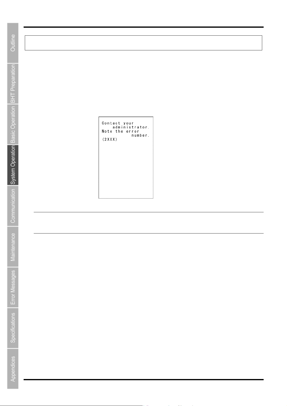
• The following message displays on the screen when the BHT is turned on.
- Point - By initializing the system, all files in the user area are deleted, and therefore all files that need to be
backed up should be uploaded to the host computer and so on beforehand.
Refer to section “4.5.3 Uploading Files (UPLOAD Menu)” for details of uploading.
The initialization procedure is described on the following pages.
Perform operation in accordance with the procedure for each item.
ν Selecting the Memory Area to be Initialized
↓
ν Selecting the Message Version (English or Japanese)
↓
ν Confirming the Memory Area to be Selected for Initialization
↓
ν Performing System Initialization
34
Page 48
Barcode Handy Terminal
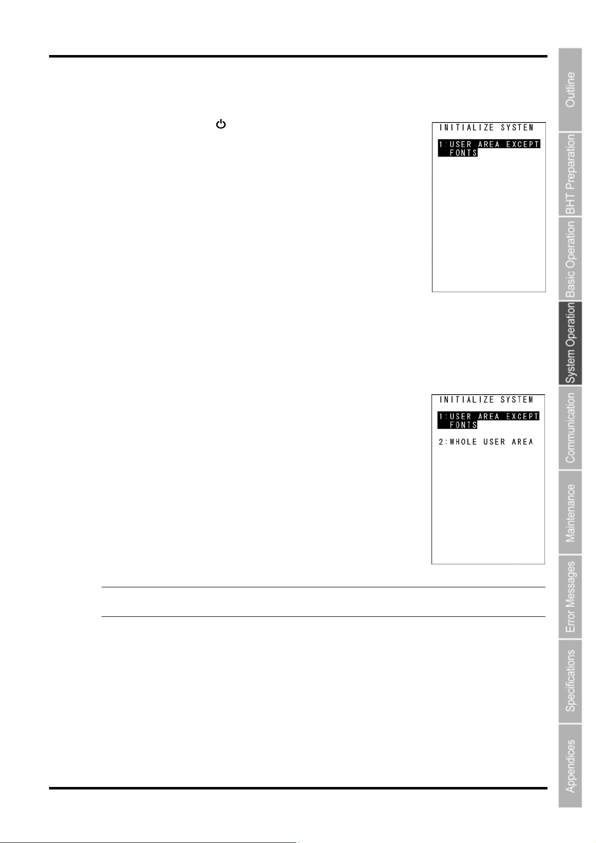
4.1.1 Selecting the Memory Area to be Initialized
1. Press the Power key ( ) while holding down the SF, M1 and 0
keys together.
The screen displays as shown on the right.
2. Select the memory area to be initialized.
(1) To exempt font files from deletion:
Ensure that “1:USER AREA EXCEPT FONTS” is selected and press the ENT key.
The screen changes to the “4.1.3 Confirming the Memory Area Selected for Initialization”.
(2) To delete font files:
Press the 2 key while holding down the SF key.
The screen displays as shown on the right.
Next, press the 2 key, select “2:WHOLE USER AREA”, and press the ENT
key.
The screen changes to the “4.1.2 Selecting the Message Version (English
or Japanese)”.
“1: USER AREA EXCEPT FONTS”
The user area is initialized without deleting file fonts.
“2: WHOLE USER AREA”
The entire user area is initialized and therefore file fonts are also
deleted.
- Point - If a “Contact the administrator. (2XXX)” message displays when the BHT power is ON,
select ”2: WHOLE USER AREA”.
35
Page 49
BHT-805B
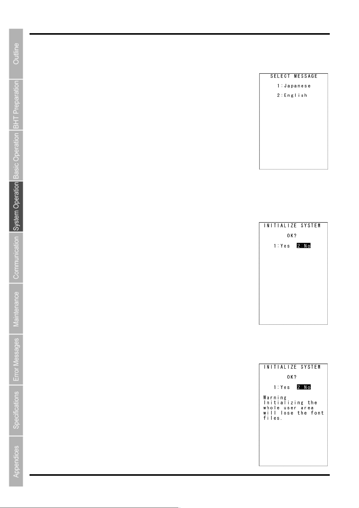
4.1.2 Selecting the Message Version (English or Japanese)
1. When the screen displays as shown on the right, select the
message display language with the numerical keys.
“1: Japanese” Changes the message language to Japanese.
“2: English” Changes the message language to English.
2. Press the ENT key.
Proceed to the operation at section “4.1.3 Confirming the Memory Area
Selected for Initialization”.
4.1.3 Confirming the Memory Area Selected for Initialization
(1) To exempt font files from deletion:
When the screen displays as shown on the right, select the item and
press the ENT key.
Press the BS/C key to return to the screen to select the area for
initialization.
“1: Yes”:
The system will be initialized without deleting font files.
“2: No”:
Cancels system initialization and turns the BHT power OFF.
(2) To delete font files:
When the screen displays as shown on the right, select the item and
press the ENT key.
36
Press the BS/C key to return to the screen to select the area for
initialization.
“1: Yes”:
The system will be initialized, and all files in the user area, including font
files, will be deleted.
“2: No”:
Cancels system initialization and turns the BHT power OFF.
Page 50
Barcode Handy Terminal
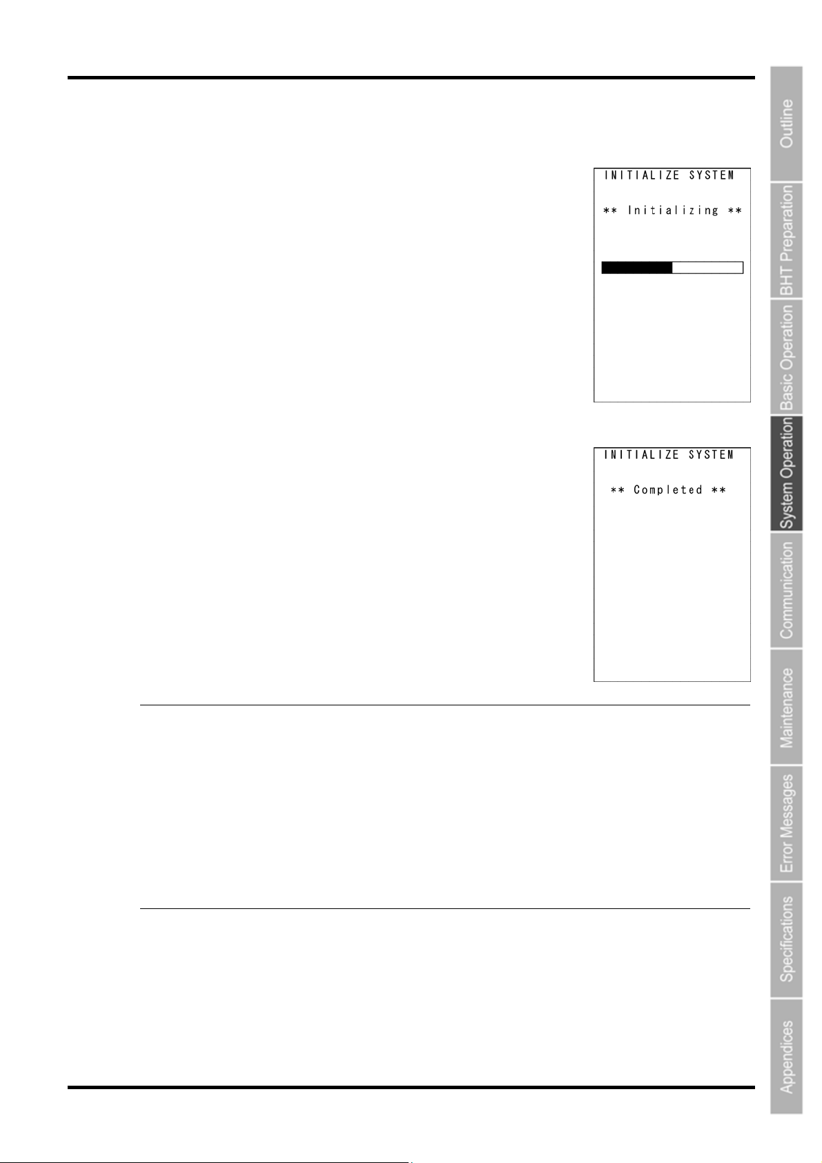
4.1.4 Performing System Initialization
1. The screen displays as shown on the right during system
initialization.
2. Upon completion of system initialization, the BHT displays the
screen on the right for a second and then turns OFF automatically.
- Point - • Never turn OFF the BHT power during system initialization. Turning the power OFF too
early will interrupt the process, requiring initialization to be performed again.
• If a “Contact your administrator. Note the error number. (XXXX)” message displays even
although initialization has been completed, initialize the BHT again.
• Following initialization, all programs and data files stored in the target memory area will be
lost. Download them again if necessary. (Refer to section “4.5.2 Downloading Files
(DOWNLOAD Menu)” for details of downloading.)
• Always set the calendar clock following initialization. (Refer to “Chapter 2 BHT
Preparation“ – “2.4 Initial Setup”.)
• Initialization will restore the display contrast level, communication conditions and other
settings to their default values when shipped from the factory, and therefore they should
be edited if necessary.
37
Page 51
BHT-805B
4.2 Updating the System
4.2.1 Updating the BHT System
The BHT system update procedure is as follows.
BHT System Update File Download
↓
BHT System Update
BHT System Update File Download
Refer to sections “4.5.3 Downloading Files (DOWNLOAD Menu)” and ”4.5.9 Downloading/Uploading Files
by FTP (FTP MENU)”, and download the BHT system update file to the BHT.
- Note - The BHT system update file can be downloaded from the following Web site.
http://www.denso-wave.com/en/
BHT System Update
Refer to section “4.5.16 Updating the System (MODIFY MENU)” and update the BHT system.
- Important -
In order to prevent the battery running low during the system update process, perform the
system update with the battery sufficiently charged, or with the BHT placed in the CU-800
Series. If the BHT power turns OFF due to a low battery and so on during the system
update, the system update will continue when the power is next turned ON. Furthermore,
during system update, the power will not turn OFF even if the Power key (
Wait until the system update process is complete before operating the BHT.
) is pressed.
38
Page 52

4.2.2 CU-811 System Update
The CU-811 system update procedure is as follows.
CU-811 System Update File Download
↓
CU-811 System Update
CU-811 System Update File Download
Refer to sections “4.5.3 Downloading Files (DOWNLOAD Menu)” and ”4.5.9 Downloading/Uploading Files
by FTP (FTP MENU)”, and download the CU-811 system update file to the BHT.
Download the CU-811 system update file as a data file with field length of 64 bytes.
- Important - If the Transfer Utility is used to download in BHT protocol, select the “Perform binary file
transfer (F)” check box at the Transfer Utility Options screen and then download.
- Note - The CU-811 system update file can be downloaded from the following Web site.
http://www.denso-wave.com/en/
Barcode Handy Terminal
CU-811 System Update
Refer to section “4.5.16 Updating the System (MODIFY MENU)” and update the CU-811 system.
The CU-811 LED flashes during CU-811 system update.
- Important - Never remove the BHT from the CU-811 or turn the BHT power OFF during the system
update process.
If the BHT is removed from the CU-811 or the BHT power turned OFF during system update,
a system update error will occur, and the CU-811 will wait for the update to be retried.
In such a case, either perform the CU-811 system update again, or reboot the CU-811.
- Point - If the CU-811 power is turned OFF during the system update, when the power is next turned
ON, either the system prior to updating or system after updating will run.
The system running can be verified at the CU-811 System Information display.
(Refer to section ”4.5.8 System Information (SYSTEM INFORMATION Menu)” for details.)
39
Page 53
BHT-805B
4.3 Executing User Programs
User programs (application programs) can be executed using the following methods.
Select the most appropriate method to meet the objective.
4.3.1 Executing from the SYSTEM MENU “EXECUTE PROGRAM”
Select the program to be executed at the SYSTEM MENU “EXECUTE PROGRAM” menu.
In such a case, the selected program will always be executed from the start.
Refer to section ”4.5.2 Executing User Programs (EXECUTE PROGRAM Menu)” for details.
4.3.2 Automatically Executing the Program Set at the SYSTEM MENU
when Turning the Power ON
Select the program to be executed at the SYSTEM MENU “EXECUTE PROGRAM” menu, and then turn
the BHT power OFF. The selected program will executed automatically the next time the BHT power is
turned ON.
If the resume function has been set, the BHT will resume from the position in the program that was
stopped when the BHT power was last turned OFF.
Refer to section ”4.5.6 System Environment Settings (SET SYSTEM Menu)” for details.
4.3.3 Executing the First Registered Program by Turning the Power ON
(BHT System Directory Management Program Function)
If no program has been selected at the SYSTEM MENU “EXECUTE PROGRAM” menu and the BHT
power is turned ON, control will switch to the directory management program, and the first of the programs
(.PD4) registered in the BHT will be executed.
If the resume function has been set, the BHT will resume from the position in the program that was
stopped when the BHT power was last turned OFF.
If downloading multiple programs after system initialization, programs are registered in the system in the
order in which they are downloaded, and therefore ensure that the program to be executed is the first
program downloaded.
If a program is later downloaded for purpose of upgrading the version, use the same program name. The
order in which programs are registered in the system will not change, and therefore the same program will
be executed even after upgrading the version. (∗)
∗ The system directory management program also manages files with other extensions simultaneously. If
the top file from the first registered program is deleted and a new program is downloaded, the new
program will be registered in the position vacated by the deleted file and therefore caution is advised. It
is recommended that the program to be execute after turning on the BHT power is first downloaded
following system initialization.
40
Page 54
Barcode Handy Terminal
r
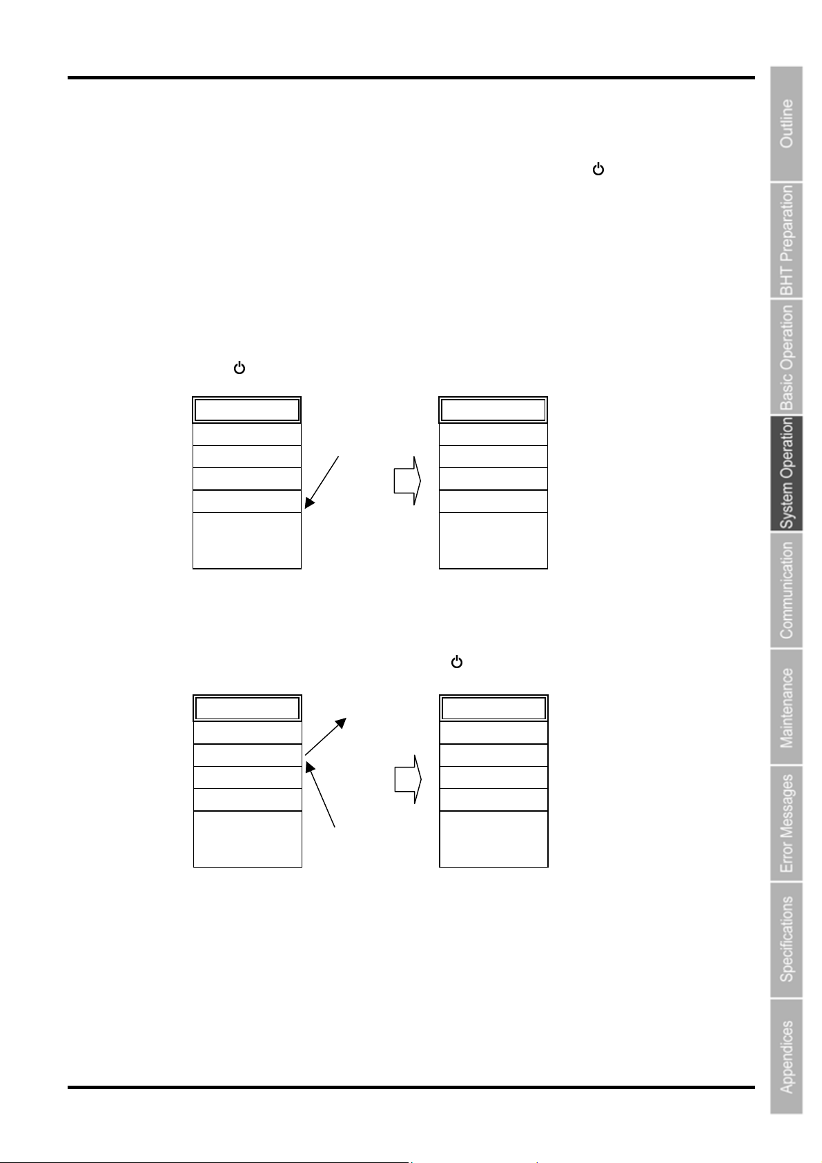
Several directory management program examples are given below.
The names of the files used in these examples are as follows.
MAIN.PD4 : Program to be executed by pressing the Power key (
SUBMAIN.PD4 : Program chained from MAIN.PD4 using the BHT-BASIC CHAIN
statement
USER.PD4 : New program
AAAAAAAA.DAT : Data file 1 used at the user program
BBBBBBBB.DAT : Data file 2 used at the user program
(Example 1) When downloading the MAIN.PD4 and SUBMAIN.PD4 upgrade version
In the above case, the registration order does not change and therefore MAIN.PD4 starts up by pressing
the Power key (
).
) only
AAAAAAAA.DAT
BBBBBBBB.DAT
MAIN.PD4
SUBMAIN.PD4
:
:
:
• MAIN.PD4
(Upgrade ver.)
• SUBMAIN.PD4
(Upgrade ver.)
Download
Directory infoDirectory info
AAAAAAAA.DAT
BBBBBBBB.DAT
MAIN.PD4
SUBMAIN.PD4
:
:
:
(Example 2) When newly downloading USER.PD4 after deleting BBBBBBBB.DAT
In the above case, USER.PD4 is registered after BBBBBBBB.DAT, and therefore USER.PD4 will be
the first registered program. Press the Power key (
Di
ectory info
AAAAAAAA.DAT
BBBBBBBB.DAT
MAIN.PD4
SUBMAIN.PD4
:
:
Delete
Download
USER.PD4
) to start up USER.PD4.
Directory info
AAAAAAAA.DAT
USER.PD4
MAIN.PD4
SUBMAIN.PD4
:
:
41
Page 55
BHT-805B
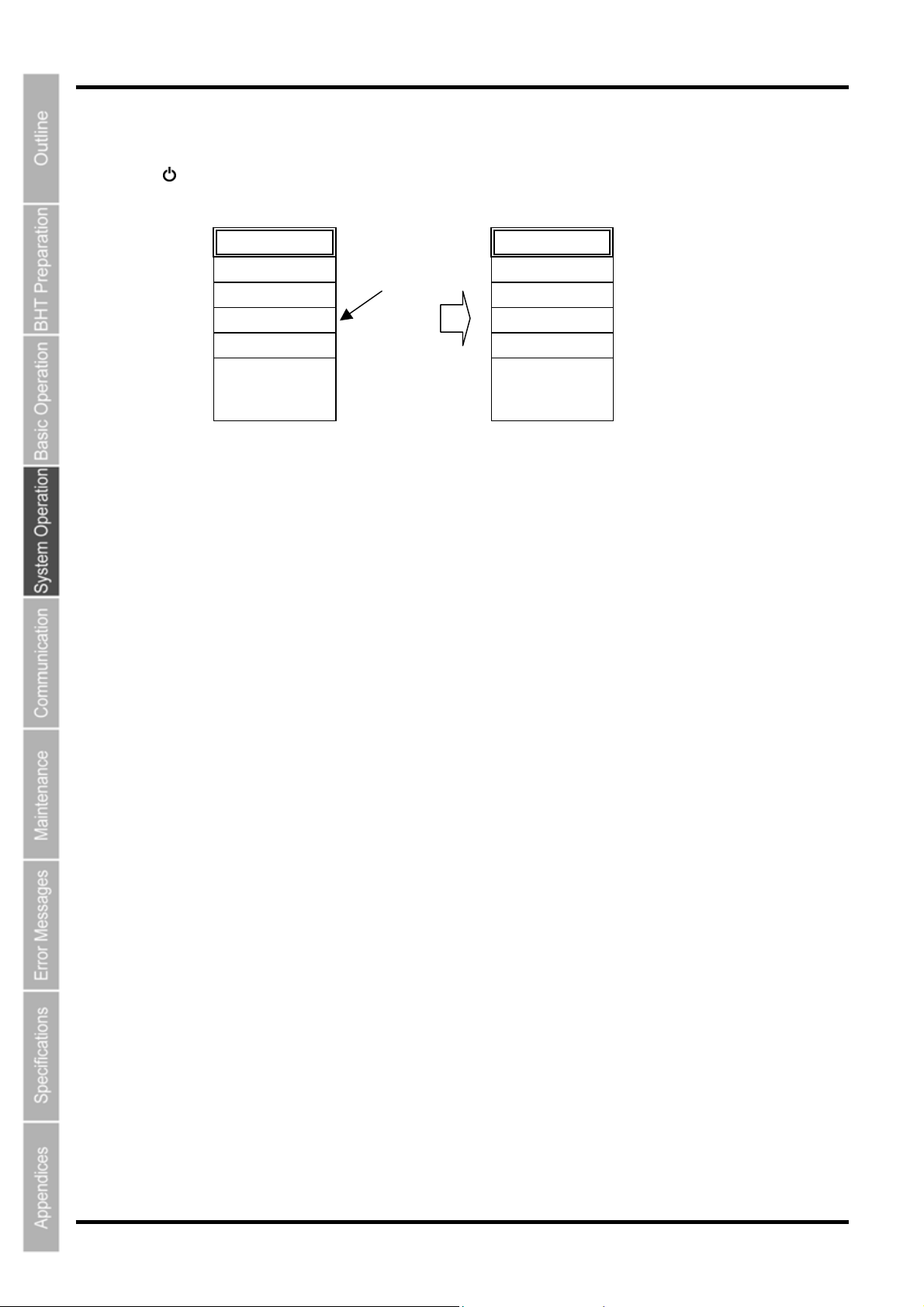
(Example 3) Recommended download method
After system initialization, first download the program to be executed simply by pressing the Power key
(
). In this case, this program is always registered at the beginning of the system directory management
unless the program has been deleted and another file downloaded.
<Status following system initialization>
Directory info
:
:
:
(1) MAIN.PD4
(2) SUBMAIN.PD4
(3) AAAAAAAA.DAT
(4) BBBBBBBB.DAT
4.3.4 Executing by Wake-up
Download in
the order (1),
(2), (3), (4).
Directory info
MAIN.PD4
SUBMAIN.PD4
AAAAAAAA.DAT
BBBBBBBB.DAT
:
:
:
By specifying the wake-up time at the user program, the BHT can be started up at the wake-up time and a
program executed.
If an auto-start execution program has been selected at the System Mode ”4.5.6 [1] Setting the auto-start
execution program”, the selected program will be executed.
If no auto-start execution program has been selected, the first registered program from among the
programs (.PD4) registered in the BHT will be executed.
Refer to the “BHT-BASIC Programmer’s Manual” for details.
4.3.5 Executing by Remote Wake-up
If remote wake-up is enabled, the BHT can be started up by receiving a control command from the host
computer. If a fixed file called “BHTRMT.PD4” exists in the BHT at this time, BHTRMT.PD4 will be
executed.
In other words, it is possible to execute the desired program by chaining from BHTRMT.PD4 using a
BHT-BASIC CHAIN statement.
Refer to ”4.5.14 Setting the Remote Wake-up (SET REMOTE WAKEUP Menu)” and the “BHT-BASIC
Programmer’s Manual” for details.
42
Page 56
Barcode Handy Terminal
4.4 System Mode
By starting up the BHT in System Mode and selecting each menu, the following operations can be performed
individually.
• Setup initialization
• Executing user programs
• File download/upload
• System environment setting
• BHT operation test
• System information display
• Downloading/uploading files by FTP
• File deletion
• Font file deletion
• System settings parameter file download/upload
• Remote wake-up setting
• System message file download/upload
• System update
Refer to each item at the “4.5 SYSTEM MENU” for details of the above operations.
4.4.1 Starting Up System Mode
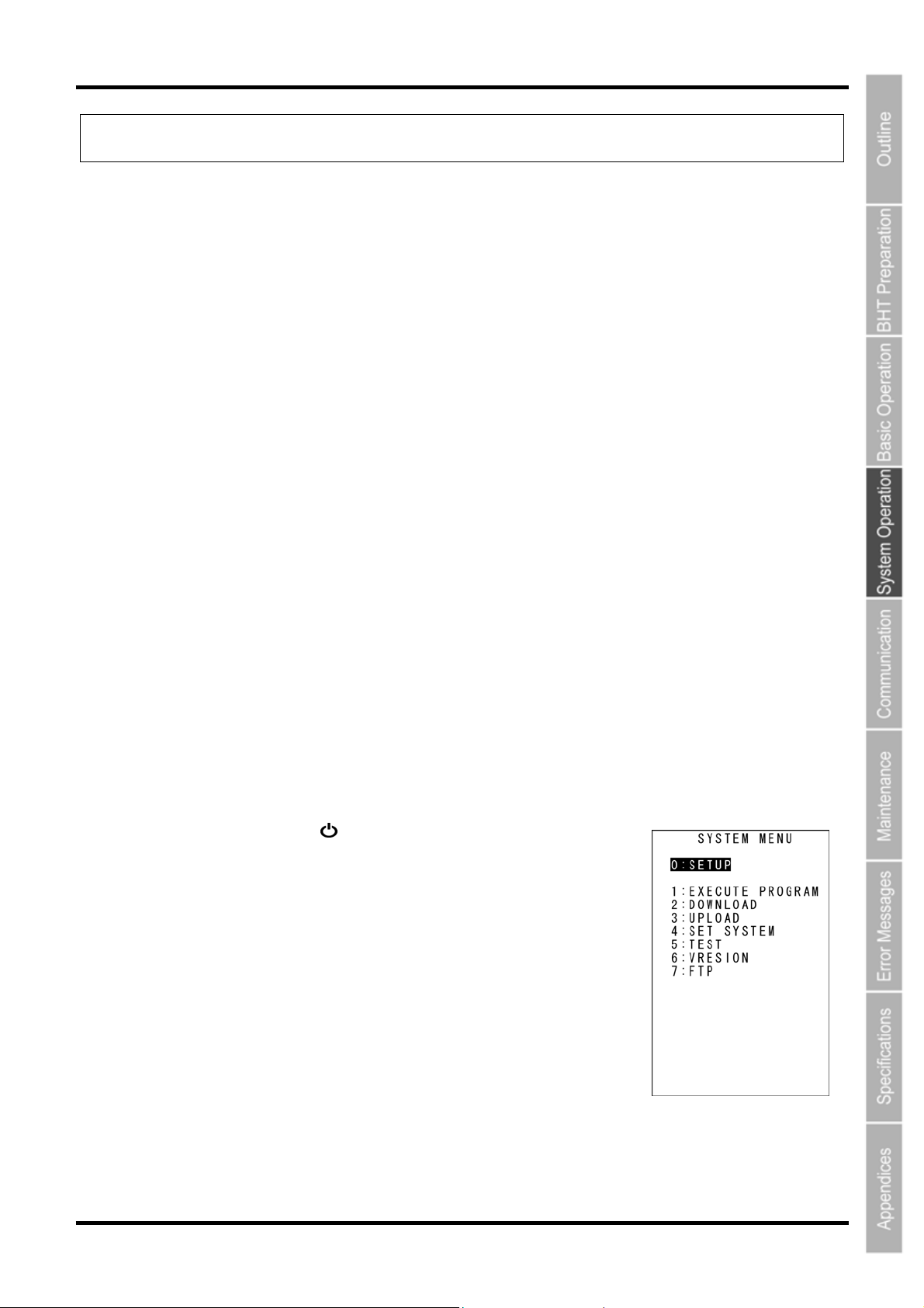
Use the following procedure to start up System Mode.
1. Press the Power key ( ) while holding down the SF and 1 keys.
System Mode starts up and the SYSTEM MENU (screen on right)
displays.
Select and display each menu from the SYSTEM MENU and perform
each operation.
Hold down the SF key and press the appropriate numerical key to display
items not displayed at the SYSTEM MENU.
Refer to ”4.4.3 SYSTEM MENU Configuration” for details.
43
Page 57
BHT-805B
4.4.2 System Mode Basic Operation
Menu Selection and Display
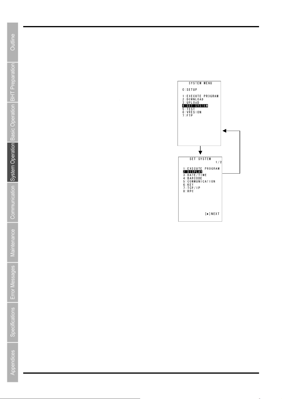
Use the following procedure to select and display each menu.
1. Press the numerical key
corresponding to the menu to
be selected.
Alternatively, press the cursor
keys ([▲] [▼]) to select the
menu.
The selected menu item will be
highlighted.
”SETUP” will be highlighted when
System Mode is started up.
Select [4:SET SYSTEM] with
Select [4: SET SYSTEM] with
the [4] or [▲]/[▼] keys.
the [4] or [▲]/[▼] keys.
Operation example
2. Press the ENT key.
The selected item is set and the
next screen displays.
Press the BS/C key to return to
the previous screen.
The selected item will be
highlighted when returning to the
previous screen.
3. Repeat the above operation to
display the target menu.
ENT key
Select [5:COMMUNICATION]
Select [2: DISPLA
with the [5] or [▲]/[▼] keys.
[2] or [
▲]/[▼] keys.
Y] with the
BS/C key
[BS/C] key
44
Page 58
Barcode Handy Terminal
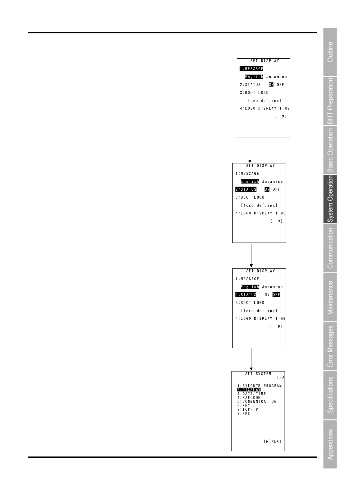
Setting Value Selection
Use the following procedure to select setting values.
1. Press the numerical key corresponding to the item to be
selected.
Alternatively, press the cursor keys ([▲] [▼]) to select the item.
The selected item will be highlighted.
2. Select the setting value with the cursor keys ([◄] [►]).
3. Press the ENT key.
The selected setting value will be set.
Operation example
Select the setting item with the
[2] key or [▲]/[▼] keys.
Select the setting value with
the cursor keys ([◄] [►]).
ENT key
45
Page 59
BHT-805B
4.4.3 SYSTEM MENU Configuration
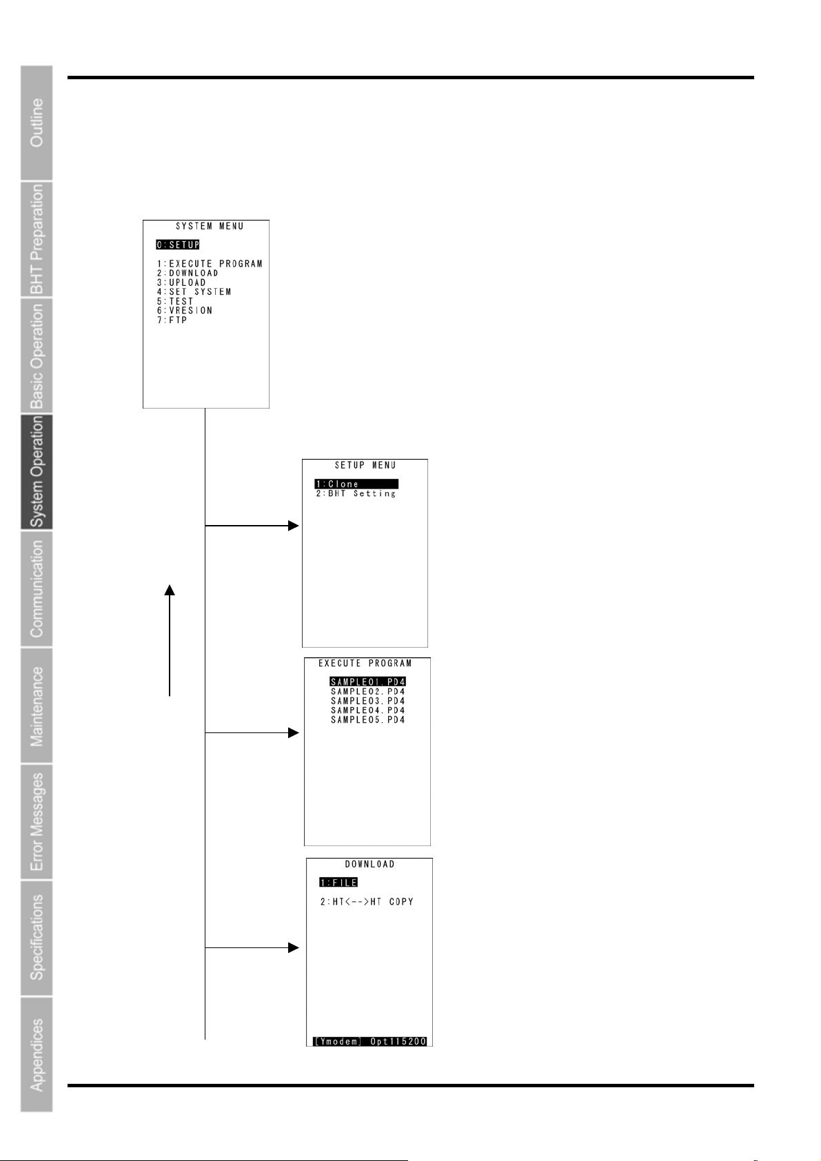
Menu Configuration for Items Displayed at the SYSTEM MENU Screen
Select the item with the numerical keys or cursor keys ([▲] [▼]) and press the ENT key.
BS/C
key
0 and ENT keys
1 and ENT keys
2 and ENT keys
SYSTEM MENU
Setup Menu
Refer to section “4.5.1 Setup”.
Executing Programs
Refer to section “4.5.2 Executing User Programs”.
Downloading
Refer to section “4.5.3 Downloading Files”.
46
Page 60
Barcode Handy Terminal
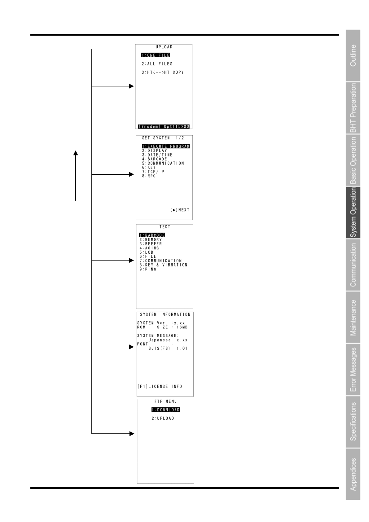
y
Uploading
Refer to section “4.5.4 Uploading Files”.
3 and ENT keys
System Environment Setting
Refer to section “4.5.6 System Environment Setting”.
4 and ENT keys
BS/C
key
Testing
Refer to section “4.5.7 BHT Operation Test”.
5 and ENT keys
System Information Display
Refer to section “4.5.8 System Information Display”.
6 and ENT keys
7 and ENT keys
Downloading/Uploading by FTP
Refer to section “4.5.9 Downloading/Uploading Files b
FTP”.
47
Page 61
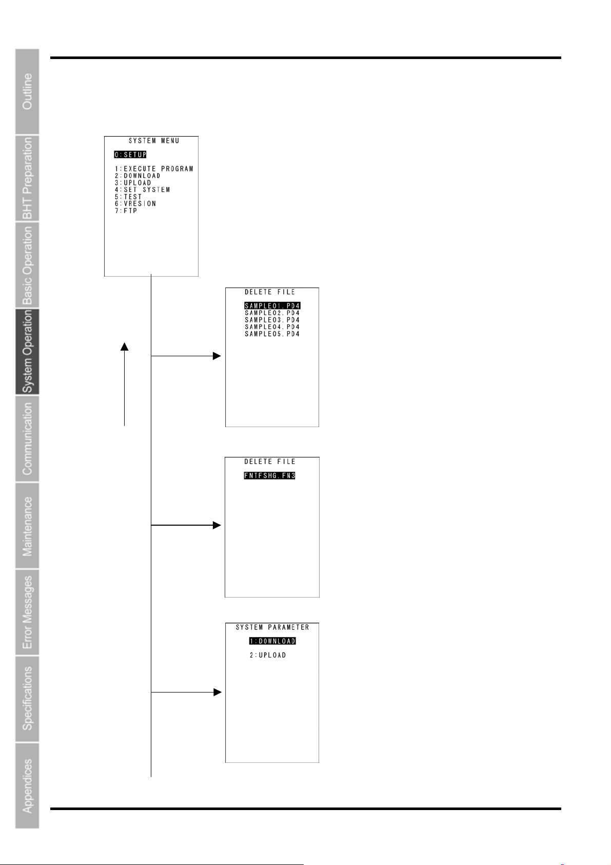
BHT-805B
T
Menu Configuration for Items Not Displayed at the SYSTEM MENU Screen
Press the corresponding numerical key while holding down the SF key.
BS/C
key
0 with SF
held down
2 with SF
held down
3 with SF
held down
SYSTEM MENU
Deleting Program/Data Files
Refer to section “4.5.11 Deleting Program/Data Files”.
Deleting Font Files
Refer to section “4.5.12 Deleting Font Files”.
Downloading/Uploading the BHT System Parameter File
Refer to section “4.5.13 Downloading/Uploading the BH
System Parameter File”.
48
Page 62
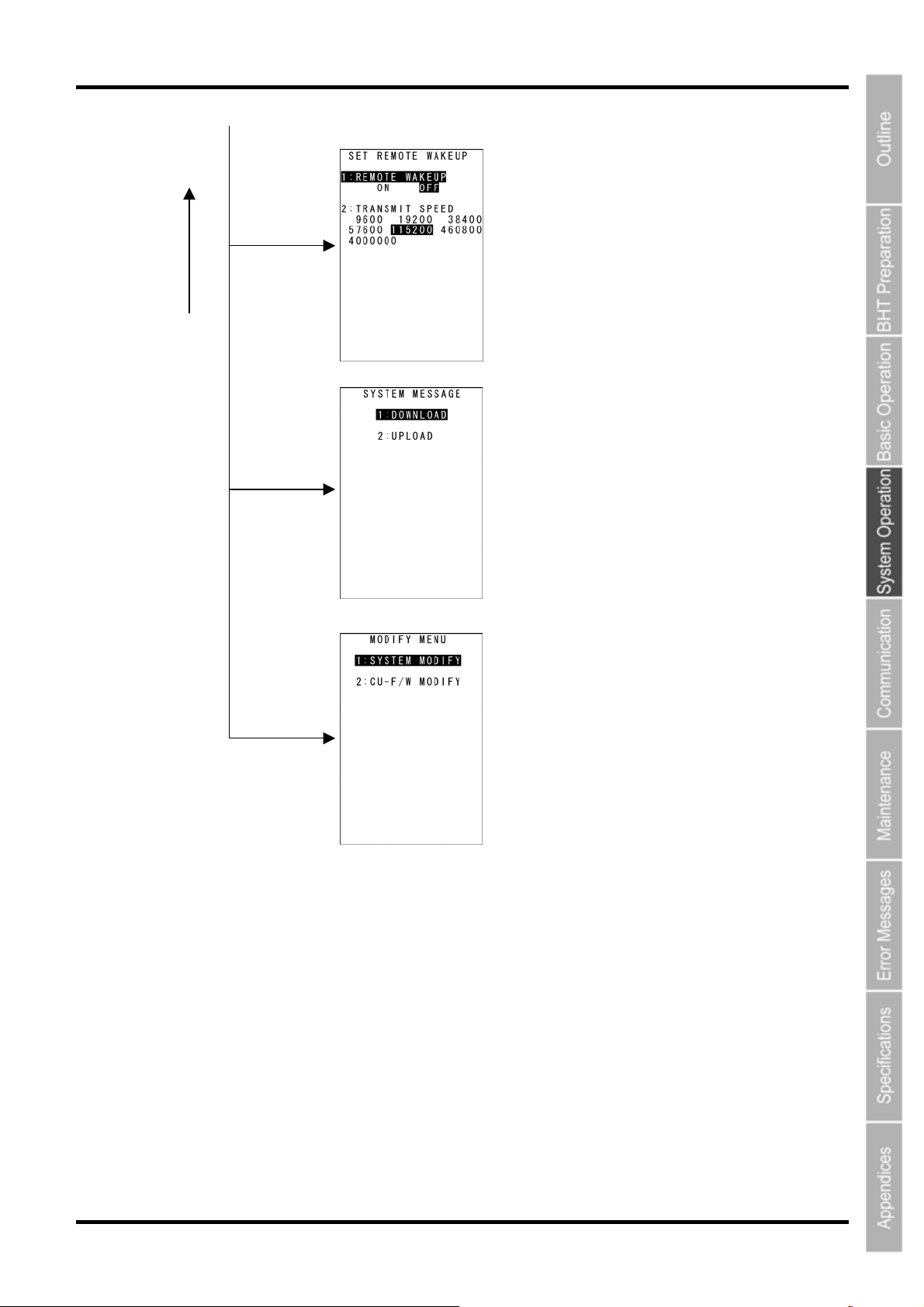
Barcode Handy Terminal
BS/C
key
4 with SF
held down
6 with SF
held down
Dot [.]
with SF held
down
Setting Remote Wake-up
Refer to section “4.5.14 Setting Remote Wake-up”.
Downloading/Uploading the System Message File
Refer to section “4.5.15 Downloading/Uploading System
the Message File”.
Updating the System
Refer to section “4.5.16 Updating the System”.
49
Page 63
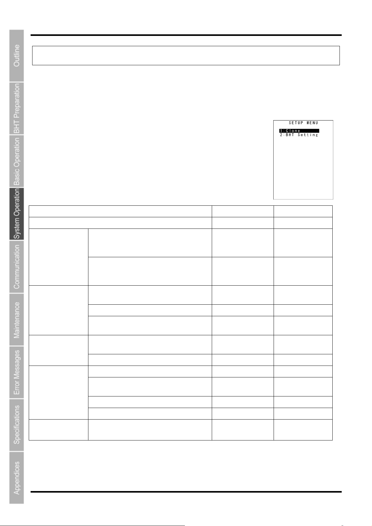
BHT-805B
4.5 SYSTEM MENU
4.5.1 Executing Setup (SETUP Menu)
The BHT setup can be effectively executed using the BHT Setting and clone functions.
The following explains setup using two BHTs with the clone function. Use the procedure below for BHT
setup.
1. Select “0: SETUP” at the SYSTEM MENU and then press the ENT key.
The screen displays as shown on the right.
“1: CLONE”:
Select to use two BHTs to create a BHT clone (s).
The clone function resembles the conventional HT-HT copy function,
but differs according to the points in the table below.
“2:BHT Setting”:
For details, refer to the “BHT Setting User’s Manual.”
Function Clone HT-HT Copy
OS Copy Available Not Available
Overwrite copy
Available Available
Available Not Available
Available Available
Available Not Available
Displayed for Each
Item
Designations
Available
File Forwarding
Progression Only
No Designations
Available
File Copy
OS Setting Values
Copy
Display
Setting Values
(The file in the receiving device is overwritten
by the file from the transmitting device.)
Clone
(Files in both the receiving and transmitting
devices are identical.) [Default]
General system setting values (excluding the
items below.)
Password settings for wireless/FTP, etc. Available Not Available
IP characteristic value (only when “0.0.0.0")
copy
Progressive display
History (usage history) Available Not Available
Target clone selection (OS) Available Not Available
Post-function execution operations (reboot
designations, etc.)
Copy mode (overwrite/clone) Available Not Available
Authentication key (*1) Available Not Available
Operational
Environment
(*1): The authentication key is protected due to password cloning for wireless/FTP, etc.
Press the BS/C key to return to the SYSTEM MENU.
50
Communication settings
Fixed
(IrDA: 460800)
Optional
Page 64
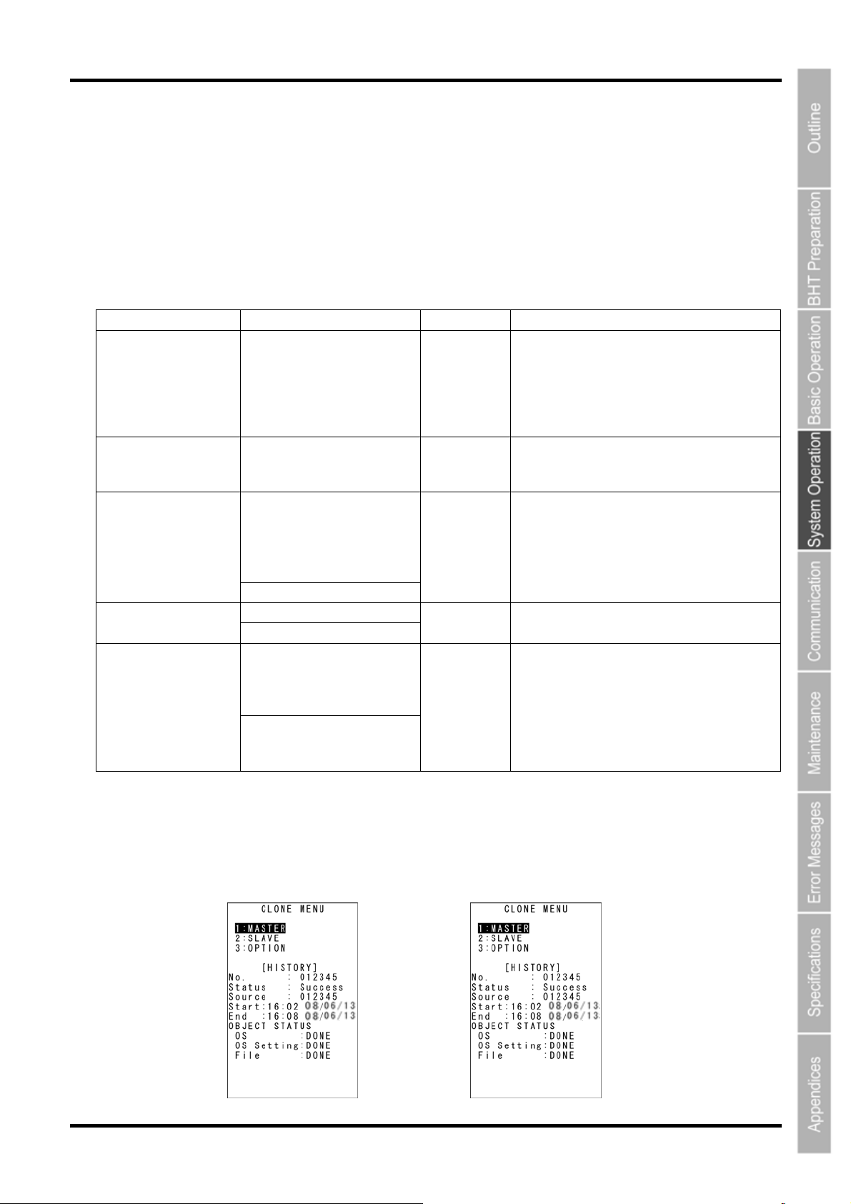
Barcode Handy Terminal
2. Execute the master-side setup.
Setup is performed with the BHT Setting and other SYSTEM MENU functions.
3. Perform the settings for the master-side clone using “2: CLONE” and “3:OPTION” from the
SETUP menu.
Use the “OPTION” menu to perform settings such as the clone number, and authentication key.
“OPTION” menu content is as per the table below.
Item Setting Content Default Remarks
Differentiates whether or not the beginning
of the number is padded with a “0” so that
1: CLONE NO.
2: SOFTWAVE TO
CLONE
3: AUTH KEY
4: SLAVE ACTION
5: FILE COPY MODE
1 to 6-digit numeric values “0”
OS YES
Used
0 to 16 one-byte
alphanumeric characters
(Entry possible in ALP
mode.)
Not used
Clone menu
BHT reboot
Clone mode
Makes the slave-side file
structure identical to the
master-side structure.
HT-HT copy mode
Leaves a copy of the
slave-side files.
Not used
Clone menu
Clone mode
the not only sequential numbers, but date
settings can be performed as well.
Ex.: The function differentiates
between ”1” and ”000001”.
There are also OS settings and additional
files, but the aforementioned items are
always cloned.
BHT reboot: Restarts the BHT, then starts
the applications.
4. Select “1: MASTER” from the master-side CLONE MENU.
5. Select “2: SLAVE” from the slave-side CLONE MENU.
Master Side Slave Side
51
Page 65
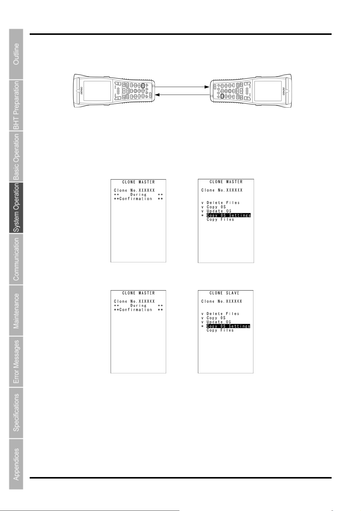
BHT-805B
(
6. Align the BHTs as shown below, and then press ENT on the transmitting device.
The data transmission progress status is shown as per the screens below.
• “∨”: Data transmission complete.
• “*”: When flashing, data transmission is in progress.
Master Side
Data
15 cm or less
Slave Side
Tes t U s e)
Master Side
→
Slave Side
→
52
Page 66
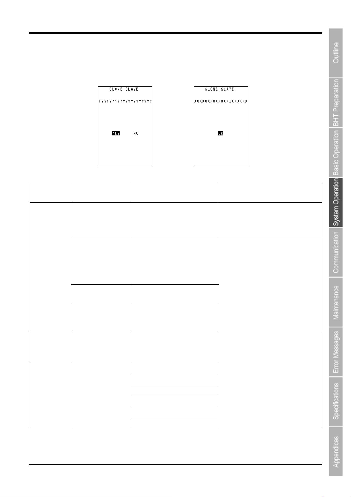
Barcode Handy Terminal
When communication is complete, the screen will return to the CLONE MENU (the previous screen.)
In the event of a communication error, “Screen 2” below will appear.
Screen 1: Error occurrenceScreen 2: Error/correctly completed
List of possible errors when cloning
Processing
Phase
Directly After
Clone Start
When Clone is
Complete
Outline Displayed Message Operations Following Error
BHT models are
different.
OS update not
possible (when
HT-HT copy mode
esignations, and
d
initialization are
required.)
Number of files
exceeded
Memory capacity
exceeded
OS settings cannot
be performed. (No
item/outside value
range.)
Different model on master side
(slave side).
Continue?
OS cannot be updated.
Cloning will be stopped.
Too many files.
Cloning will be stopped.
Insufficient memory on
slave side.
Cloning will be stopped.
Some items could not be set on
slave side. (N items)
When screen 1 appears, select Yes/No.
Y: Continue processing ( the OS and OS
settings will not be copied.)
N: Suspend processing
Screen 2 appears, and processing is
suspended.
During
Communication
Communication error
Out of memory
File mismatch
Too many files
File error
Program file error
Communication error
Screen 2 appears, and processing is
complete.
53
Page 67
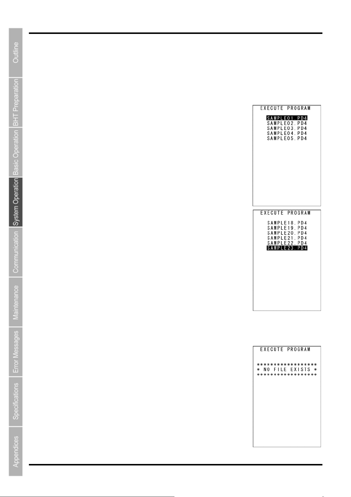
BHT-805B
4.5.2 Executing User Programs (EXECUTE PROGRAM Menu)
Individually select and execute user programs downloaded to the BHT.
Use the following procedure to execute user programs.
1. Select “1: EXECUTE PROGRAM” at the SYSTEM MENU and then
press the ENT key.
The screen displays as shown on the right.
Press the BS/C key to return to the SYSTEM MENU.
2. Use the cursor keys ([▲] [▼]) to select the target program.
The selected program will be highlighted.
Use the [▼] key to scroll down when more than 18 programs have been
downloaded to the user area.
The screen on the right shows an example in which 23 programs have
been downloaded.
3. When the target program is highlighted, press the ENT key.
The selected program will be executed.
The screen displays as shown on the right when no program files exist in
the user area.
Press the BS/C key to return to the SYSTEM MENU.
54
Page 68
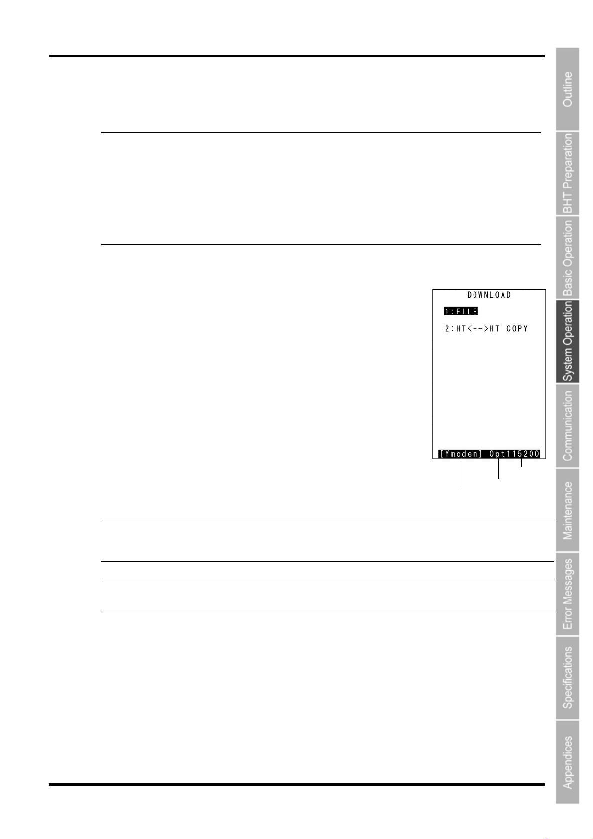
4.5.3 Downloading Files (DOWNLOAD Menu)
Download files to the BHT user area from other devices such as the host computer.
- Point -
Use the following procedure to download files.
• If a file with the same name as one already used in the user area of the target memory in
the BHT is downloaded, the newly downloaded file replaces the old one.
• If an auto-start execution program has not been specified (See 4.5.6 [1] Auto-start
Execution Program Settings), the directory management program will execute the first
managed program from among the programs (.PD4) downloaded to the BHT when the
BHT power is turned ON. (Program displayed at the top of the “EXECUTE PROGRAM”
menu) Take this into account when determining the file download order.
Refer to “4.3 Executing User Programs” for details.
1. Select “2: DOWNLOAD” at the SYSTEM MENU and then press the
ENT key.
The screen displays as shown on the right.
“1: FILE”:
Select to download a specific file.
“2: HT<-->HT COPY”:
Select to download a file from another BHT.
Refer to “4.5.5 Copying Files between 2 BHT Units” for details.
Press the BS/C key to return to the SYSTEM MENU.
The current communication settings display at the bottom of the screen.
Communication protocol type Ymodem
BHT-Ir
BHTp
Ymodem protocol
BHT-Ir protocol
BHT protocol
Barcode Handy Terminal
Transmit speed
Interface used
Communication protocol type
Interface used Opt IrDA interface
Transmit speed 9600 to 460800 Transmission speed corresponding to each
protocol
Refer to “4.5.6 (5) System Environment Settings (SET SYSTEM Menu)” for details of communication
environment settings.
55
Page 69
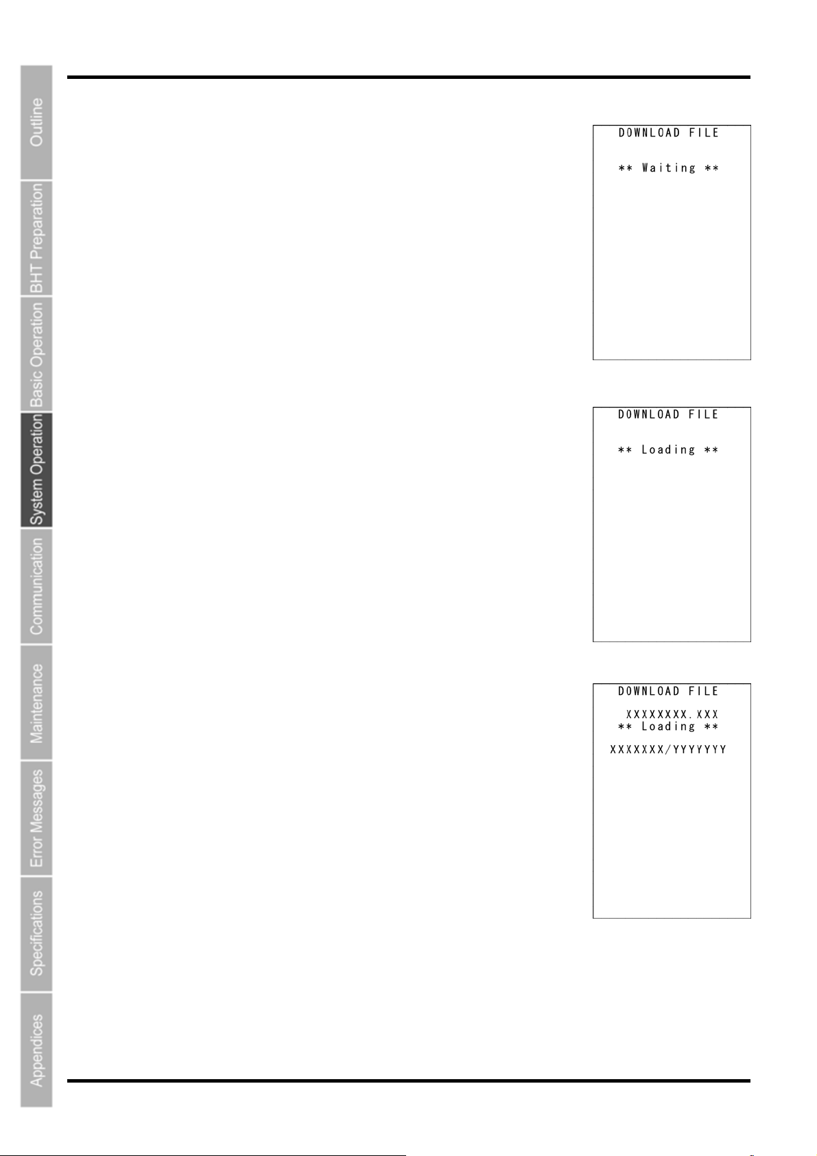
BHT-805B
2. Select either “1: FILE” or ”2: HT<-->HT COPY” and press the ENT
key.
The screen displays as shown on the right indicating that the BHT is waiting
for the file to be downloaded.
The screen displays as shown on the right only when “1: FILE” is selected.
If “2: HT<-->HT COPY” is selected, “HT<-->HT” displays in the center of the
second row of the screen.
3. By executing the BHT-BASIC 4.0 Transfer Utility or similar program,
the screen displays as shown on the right and file downloading is
commenced.
(Refer to the “BHT-BASIC 4.0 Transfer Utility User’s Guide.”)
4. The screen displays as shown on the right during downloading.
The screen displays as shown on the right indicating the file name and the
number of received records/the total number of records.
(When using the Ymodem protocol, the received file size/the total file size
(units: KB) displays.)
Press the BS/C key to abort the download process and return to the
DOWNLOAD menu.
56
Page 70
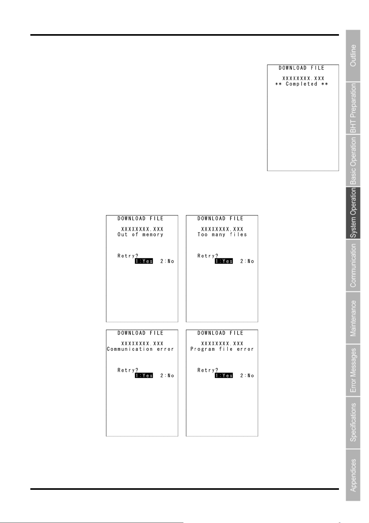
Barcode Handy Terminal
5. When downloading is complete, the speaker sounds once and the scr
een displays as shown on
the right.
When the number of received records equals the total number of records,
downloading is complete.
(When using the Ymodem protocol, the received file size equals the total
file size.)
Press the BS/C key to return to the DOWNLOAD menu.
With this screen displayed on the BHT, downloading another new file from
the host computer allows the BHT to begin receiving.
(Refer to the “BHT-BASIC 4.0 Transfer Utility User’s Guide.”)
If “2: HT<-->HT COPY” is selected, repeat the above operation until all files are downloaded.
If an error message (screen below) displays during downloading, refer to “Chapter 7 Error Messages”.
57
Page 71
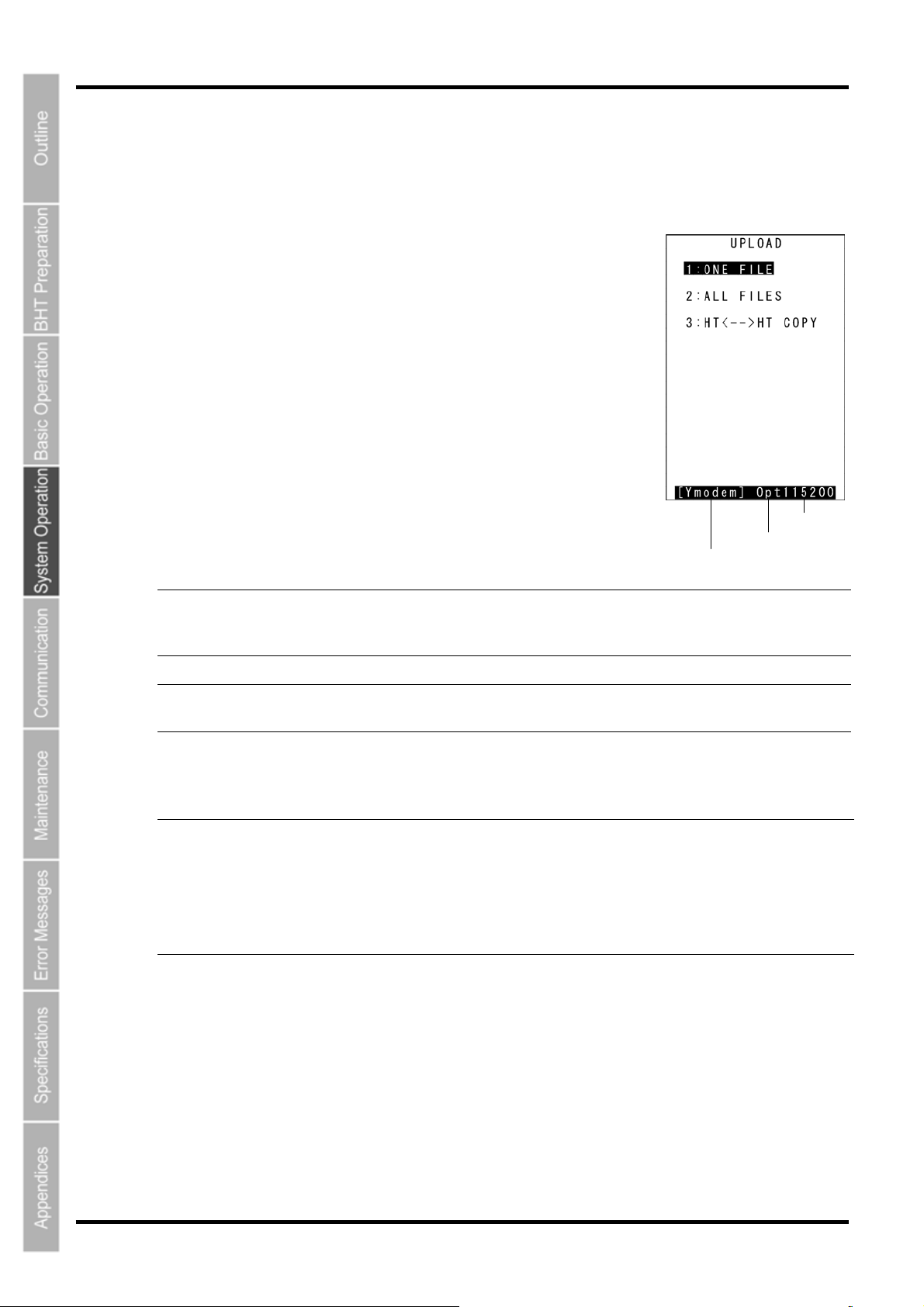
BHT-805B
r
4.5.4 Uploading Files (UPLOAD Menu)
Upload files stored in the BHT user area to another device.
Use the following procedure to upload files.
1. Select “3: UPLOAD” at the SYSTEM MENU and then press the
ENT key.
The screen displays as shown on the right.
“1: ONE FILE”:
Select to upload a specific file.
“2: ALL FILES”:
Select to upload all files, excluding font files.
“3: HT<-->HT COPY”:
Select to upload a file to another BHT.
Refer to “4.5.5 Copying Files between 2 BHT Units” for details.
Press the BS/C key to return to the SYSTEM MENU.
The current communication settings display at the bottom of the screen.
Communication protocol type Ymodem
BHT-Ir
BHTp
Ymodem protocol
BHT-Ir protocol
BHT protocol
Transmit speed
Interface used
Communication protocol type
Interface used Opt IrDA interface
Transmit speed 9600 to 460800 Transmission speed corresponding to each
protocol
Refer to “4.5.6 System Environment Settings (SET SYSTEM Menu)” for details of communication
environment settings.
- Point -
If BHT protocol or BHT-Ir protocol is selected for the communication protocol, BHT-BASIC
4.0* specification files will not display at the file selection screen, and therefore cannot be
downloaded.
(*Applications with extension “.PD4”, extension libraries with extension “.FN4”, and data files
that have any of the following structures: the number of fields is 17 or more, the total of the
number of fields and each field length is 255 or more, and the number of records is 32768 o
more)
58
Page 72
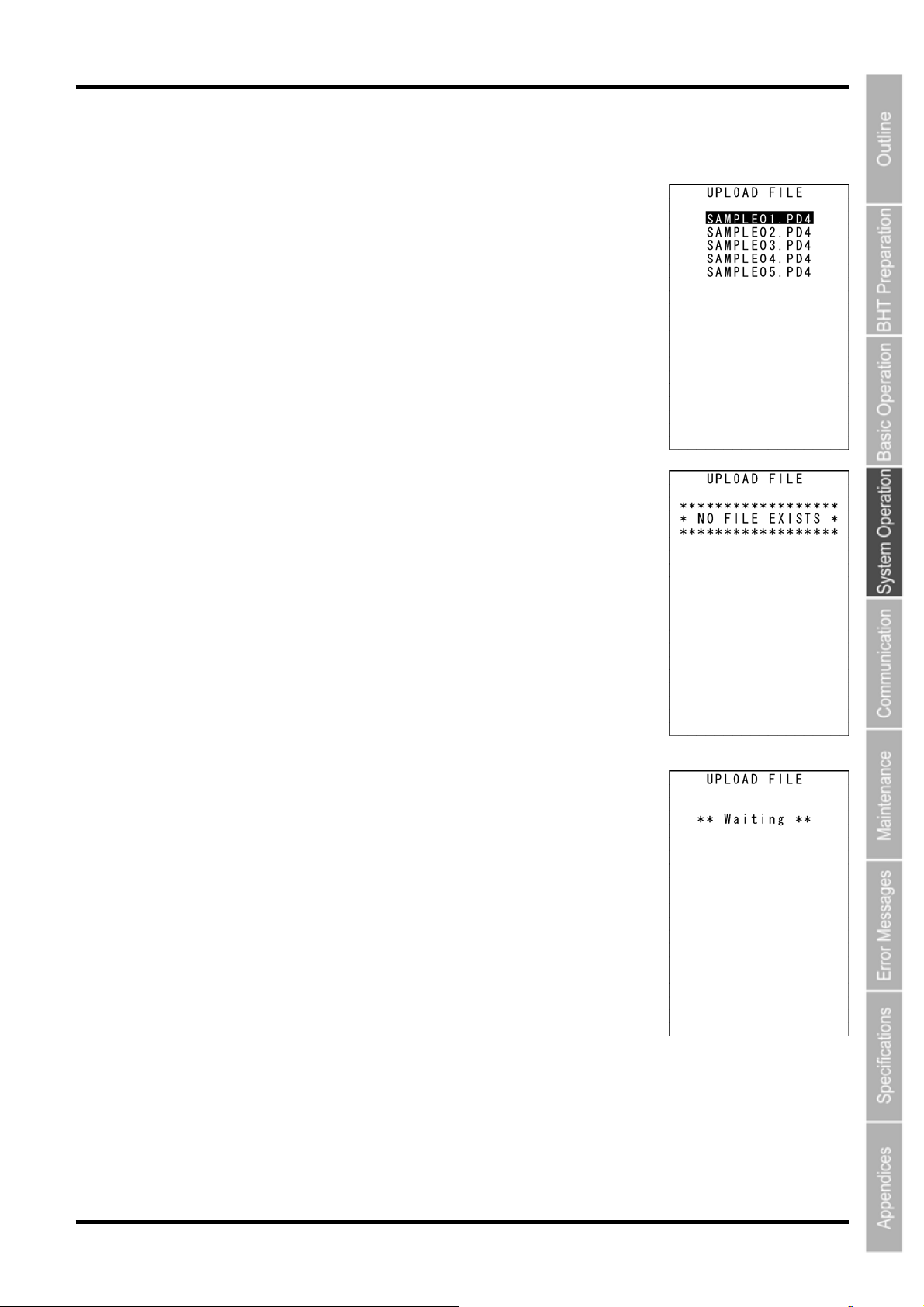
Barcode Handy Terminal
2. Select “1: FILE”, ”2: ALL FILES” or ”3: HT<-->HT COPY” and press the ENT key.
When “1: FILE” is selected:
The screen displays as shown on the right. Select the file to be uploaded
and press the ENT key.
Next, proceed to step 3.
When “2: ALL FILES” or ”3:HT<-->HT COPY” is selected:
Proceed to step 3.
The screen displays as shown on the right
exist in the user area.
Press the BS/C key to return to the UPLOAD menu.
if no files that can be uploaded
3. The screen displays as shown on the right indicating that the BHT is
waiting for the file to be uploaded.
The screen displays as shown on the right only when “1: FILE” is selected.
If “2:ALL FILES” is selected, “ALL” displays in the center of the second row
of the screen.
If “3: HT<-->HT COPY” is selected, “HT<-->HT” displays in the center of the
second row of the screen.
59
Page 73
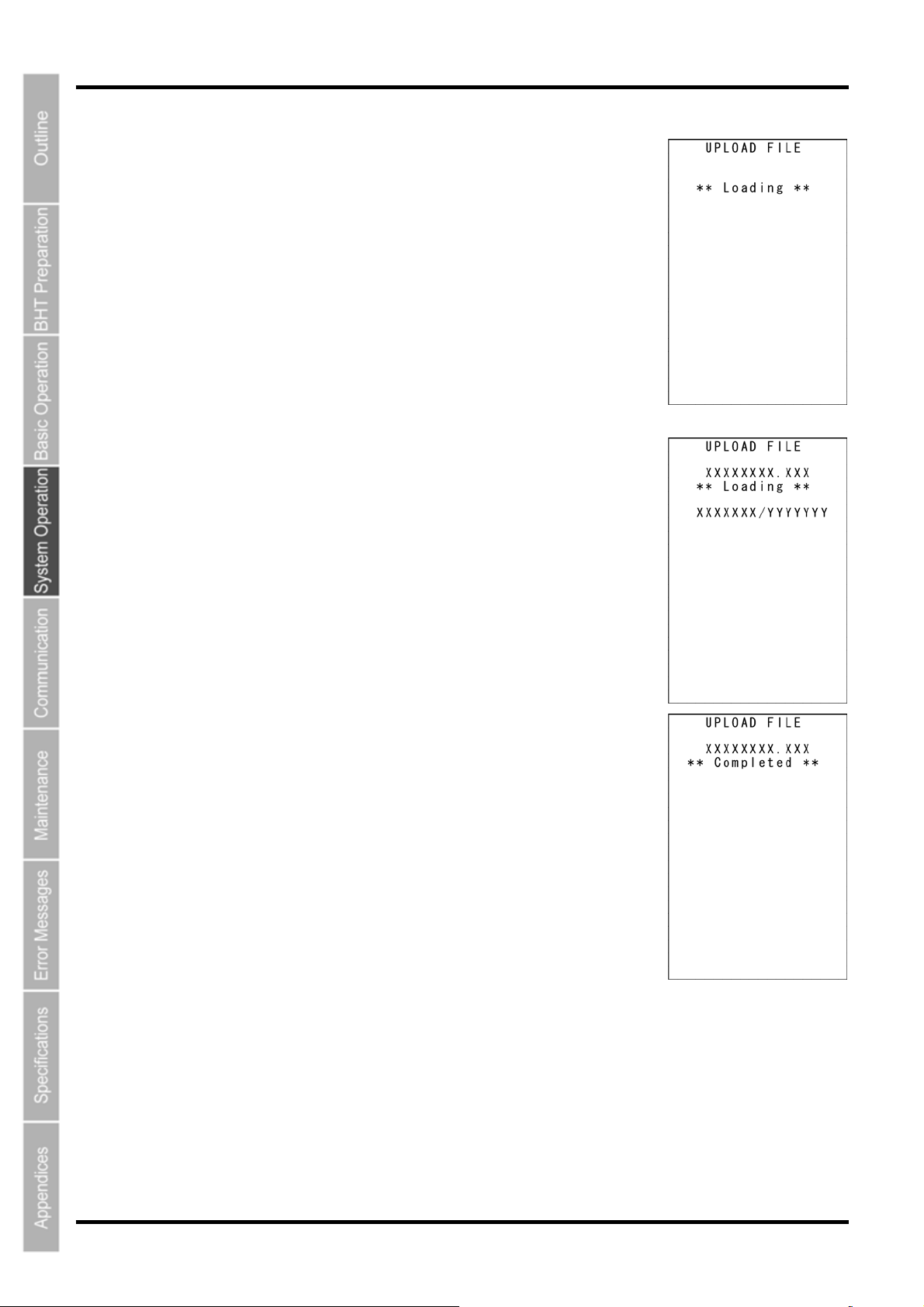
BHT-805B
4. By executing the BHT-BASIC 4.0 Transfer Utility or similar program,
the screen displays as shown on the right and file uploading is
commenced.
(Refer to the “BHT-BASIC4.0 Transfer Utility User’s Guide.”)
5. The screen displays as shown on the right during uploading.
The screen displays as shown on the right indicating the file name and the
number of sent records/the total number of records.
(When using the Ymodem protocol, the sent file size/the total file size
(units: KB) displays.)
Press the BS/C key to abort the download process and return to the
UPLOAD menu.
6. When uploading is complete, the speaker sounds once and the
screen displays as shown on the right.
When the number of sent records equals the total number of records,
downloading is complete.
(When using the Ymodem protocol, the sent file size equals the total file
size.)
Press the BS/C key to return to the UPLOAD menu.
If “2: ALL FILES” or ”3: HT<-->HT COPY” is selected, repeat the above
operation until all files are uploaded.
If an error message displays during uploading, refer to “Chapter 7 Error
Messages”.
60
Page 74

Barcode Handy Terminal
4.5.5 Copying Files between 2 BHT Units
Copy “all files (excluding font files)”, “setting data”, and the “date and time” stored in the BHT user area to
another BHT.
Use the following procedure to copy files between 2 BHT units.
1. Set the same interface at both BHT units.
An IrDA communication (Optical) interface is used.
.
2. Set “COMMUNICATION PROTOCOL OPTION” → “FIELD SPACE” (space at the end of the
field) to “Ignore” at both BHT units.
The default setting is “Ignore”.
Refer to “4.5.6 System Environment Settings (SET SYSTEM Menu)” when changing the interface.
3. Ensure that the BHT IrDA communication ports are facing one another.
4. Select “2: DOWNLOAD” → ”2: HT<-->HT COPY” at the SYSTEM MENU of the BHT that is
downloading to await downloading.
Refer to “4.5.3 Downloading Files (DOWNLOAD Menu)” for details.
When copying only the system parameter file, use the SYSTEM PARAMETER transfer menu. Refer to
“4.5.13 Downloading/Uploading the BHT System Parameter File (SYSTEM PARAMETER Menu)” for
details.
5. Select “3: UPLOAD” → ”3: HT<-->HT COPY” at the SYSTEM MENU of the BHT that is
uploading to await uploading.
Refer to the “4.5.4 Uploading Files (UPLOAD Menu)” for details.
When copying only the system parameter file, use the SYSTEM PARAMETER transfer menu. Refer to
“4.5.13 Downloading/Uploading the BHT System Parameter File (SYSTEM PARAMETER Menu)” for
details.
6. Preparation at both BHT units is now complete and file copying will be commenced.
61
Page 75
BHT-805B
- Note - The following setting data is copied when copying between BHT units.
LCD contrast level
Volume
Switching between speaker and vibrator
Program to be executed automatically when the BHT is turned ON
Message version (English or Japanese)
Backlight brightness of the LCD display
Backlight brightness of the LCD display during power save mode
Display font size
System status display
Date
Time
Setting of black-and-white inverted label reading function (enable/disable)
Decode level
Minimum number of digits to be read for ITF
Minimum number of digits to be read for STF
Minimum number of digits to be read for Codabar (NW-7)
Interface port to be used in user programs
Interface port to be used in System Mode
Communication parameters for the IrDA interface
Communication protocol options for the IrDA interface
Communication protocol type
Shift key function definition
M1 key function definition
M2 key function definition
M3 key function definition
M4 key function definition
Resume function
Remote wake-up setting (enable/disable)
Transmission speed for remote wake-up
Remote wake-up history
YMODEM option
IP address of FTP server
User name of FTP server
Password of FTP server
Default directory for FTP server
62
Page 76

FTP option, Line delimiters (CR/LF)
FTP option, Handling of line delimiters
FTP option, Handling of trailing spaces in data fields
FTP option, Upload mode
FTP option, Verbose mode
IP address of host computer for ping-test
Data size of echo request
Echo request intervals
Timeout period for echo request
No. of echo requests to be sent
Echo request send timing
TCP/IP operation device
TCP/IP link layer
Transmission speed between BHT and CU
No. of retries for link establishment command to be sent
Link establishment command intervals
No. of retries for link release command to be sent
Link release command intervals
Link release period
Maximum DHCP IP address acquisition wait time
Barcode Handy Terminal
63
Page 77
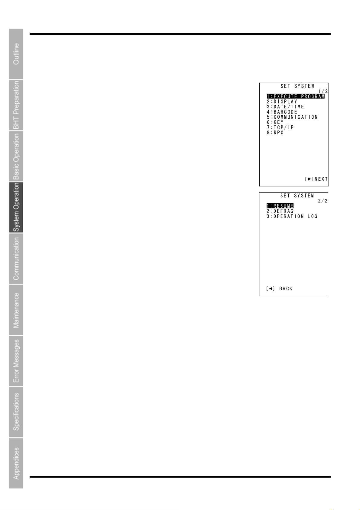
BHT-805B
4.5.6 System Environment Settings (SET SYSTEM Menu)
Use the following procedure to set the system environment.
1. Select “4: SET SYSTEM” at the SYSTEM MENU and then press the
ENT key.
The SET SYSTEM menu screen on the right displays.
SYSTEM MENU 1/2
“1: EXECUTE PROGRAM”:
Sets the auto-start execution program to be executed when the power is
turned ON.
“2: DISPLAY”:
Sets the message version (English or Japanese).
“3: DATE/TIME”:
Sets the calendar clock (date and time).
“4: BARCODE”:
Sets the barcode reading conditions (black/white inverted label reading
function and decode label) and minimum number of read digits for read
codes (ITF, STF, Codabar).
“5: COMMUNICATION”:
Sets the communication environment (interface port and communication
parameters).
“6: KEY”:
Defines the functions of the shift key and magic keys.
“7: TCP/IP”:
Displays the TCP/IP, FTP, and DHCP settings menu.
“8: RPC”:
Sets the communication method with the BHT Manager.
SYSTEM MENU 2/2
“1: RESUME”:
Sets the resume function.
“2: DEFRAG”:
Performs drive optimization.
“3: OPERATION LOG”:
Sets whether or not to create a log from data collected by the BHT Manager.
Refer to the following section for details of the above items.
Press the BS/C key to return to the SYSTEM MENU.
64
Page 78
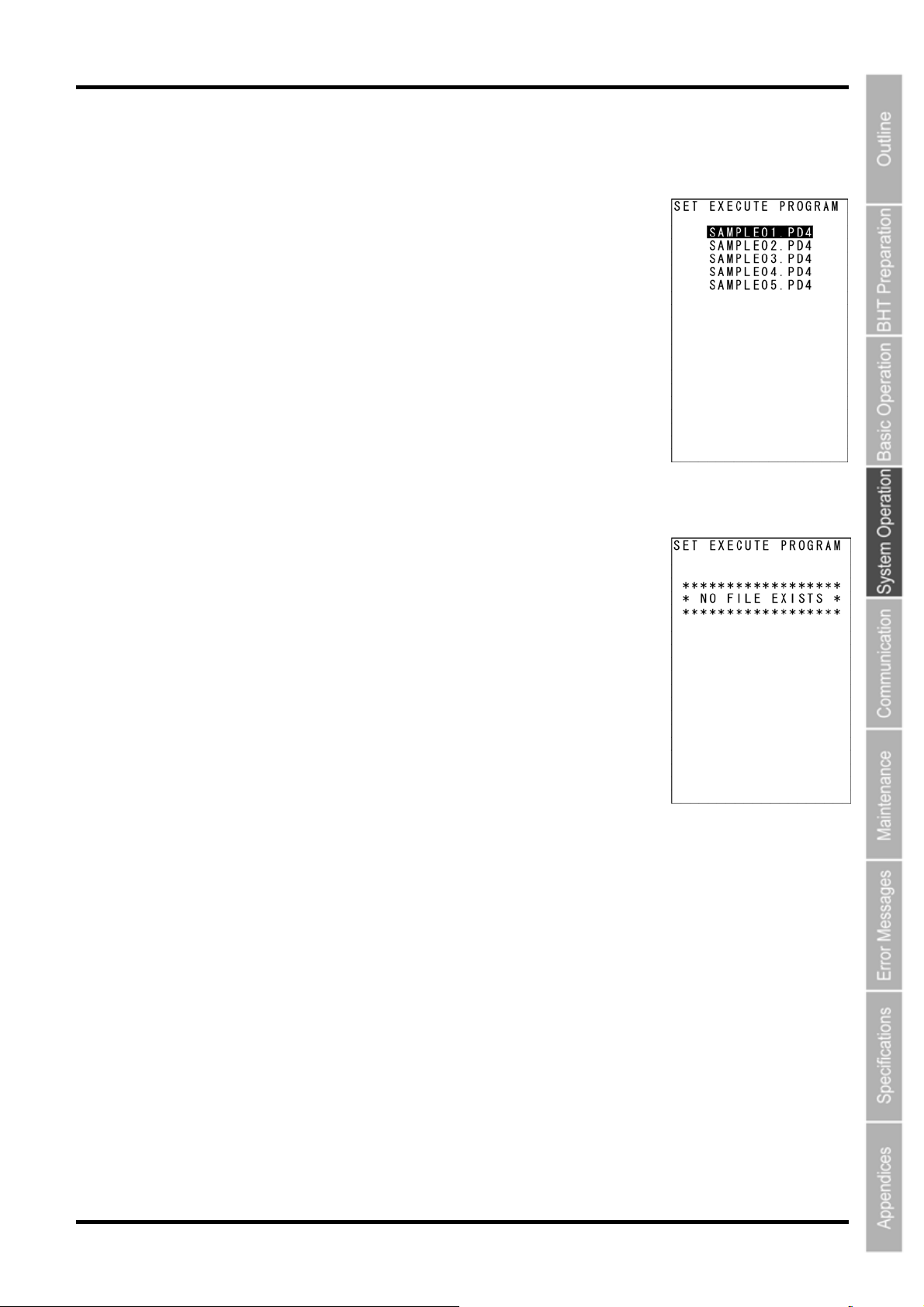
Barcode Handy Terminal
[1] Setting the auto-start execution program
Use the following procedure to set the auto-start execution program.
1. Select “1: EXECUTE PROGRAM” at the SET SYSTEM menu and
then press the ENT key.
The SET EXECUTE PROGRAM menu screen on the right displays.
The highlighted program will be the program currently set as the auto-start
execution program.
2. Use the cursor keys ([▲] [▼]) to highlight the target program.
3. Press the ENT key.
The selected program will be set as the auto-start execution program.
Press the BS/C key to return to the SET SYSTEM menu.
The screen displays as shown on the right if no programs have been
downloaded.
Press the BS/C key to return to the SET SYSTEM menu.
65
Page 79
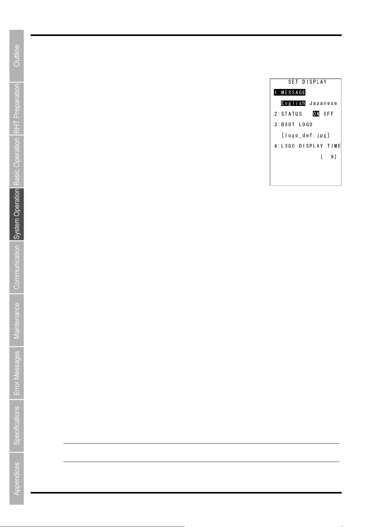
BHT-805B
r
[2] Setting the message version, system status indication and screen display compatible mode
Use the following procedure to set the display language, system status indication and screen display
compatible mode.
1. Use the cursor keys ([▲] [▼]) or numerical keys ([1] [2] [3] [4]) to
highlight ”1: MESSAGE”, ”2: STATUS”, “3: BOOT LOGO”, or “LOGO
DISPLAY TIME”.
2. Highlight the target setting with the cursor keys ([◄] [►]) and press
the ENT key.
Press the BS/C key to return to the SET SYSTEM menu.
“1: MESSAGE”:
Sets whether messages displayed at the screen are displayed in English
or Japanese.
The default is the message version selected at the system initializing process.
The English and Japanese display changes at the following messages.
• System error messages
• Indications relating to the LCD contrast
• Speaker volume
• Switching between speaker and vibrator
• Battery voltage level screens
“2: STATUS”:
Sets whether to display or hide the system status displayed at the bottom of the screen.
Refer to “System Status Indication” on the following page for details of the system status indication.
• “ON”: The system status is displayed.
• “OFF”: The system status is hidden.
“3: BOOT LOGO”:
Selects the logo displayed at startup.
The JPG file for the logo is downloaded, and then this menu is used to display the selected JPG file
upon startup.
“4: LOGO DISPLAY TIME”:
Sets the minimum time the selected logo is displayed.
• The time can be set between 9 and 100 (x 100 ms).
• When a number between 0 and 9 (x 100 ms) is set, the value is treated as a “9”.
• The display time varies according to the logo file size.
- Note - The system status indication can be turned ON or OFF using the OUT statement in use
programs. Refer to the “BHT-BASIC Programmer’s Manual.”
66
Page 80
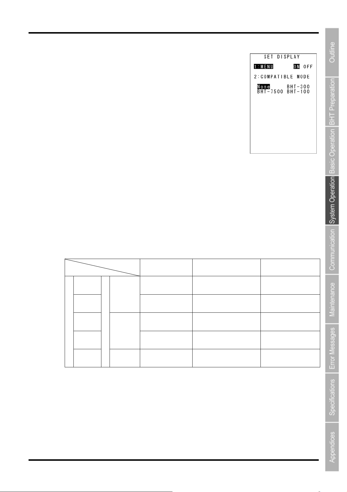
Barcode Handy Terminal
3. Simultaneously press the SF key and “1: MESSAGE” at the SET
DISPLAY menu.
The SET DISPLAY menu on the right displays.
The highlighted settings will be the current settings.
4. Use the cursor keys ([▲] [▼]) or numerical keys ([1] [2]) to
highlight ”1: MENU” or ” 2: COMPATIBLE MODE”.
5. Highlight the target setting with the cursor keys ([◄] [►]) and press
the ENT key.
Press the BS/C key to return to the SET SYSTEM menu.
“1: MENU”:
Sets whether to permit or prohibit the menu screen (speaker volume, vibrator, screen brightness, power
saving) starting up while application program is running.
• “ON”: Permits menu screen display.
• “OFF”: Prohibits menu screen display.
“2: COMPATIBLE MODE”:
Sets compatible mode for screen display with the BHT-100, BHT-300, or BHT-7500.
This allows BHT-100 Series, BHT-300 Series, or BHT-7500 Series application programs to run at the
BHT-805B without changing or correcting the font size.
BHT-300 BHT-7500 BHT-100
Standard
font
Small
font
Standard
font
Font Size
Small
font
ANK
mode
Kanji
mode
Screen mode
Reduced
Kanji
22 x 9 char.
(6 x 8 dots)
22 x 12 char.
(6 x 6 dots)
8 x 4 char.
(16 x 16 dots)
11 x 6 char.
(12 x 12 dots)
11 x 4 char.
(12 x 16 dots)
26 x 20 char.
(6 x 8 dots)
26 x 26 char.
(6 x 6 dots)
10 x 10 char.
(16 x 16 dots)
13 x 13 char.
(12 x 12 dots)
(Not supported) (Not supported)
16 x 25 char.
(12 x 12 dots)
16 x 25 char.
(12 x 12 dots)
12 x 19 char.
(16 x 16 dots)
16 x 25 char.
(12 x 12 dots)
67
Page 81
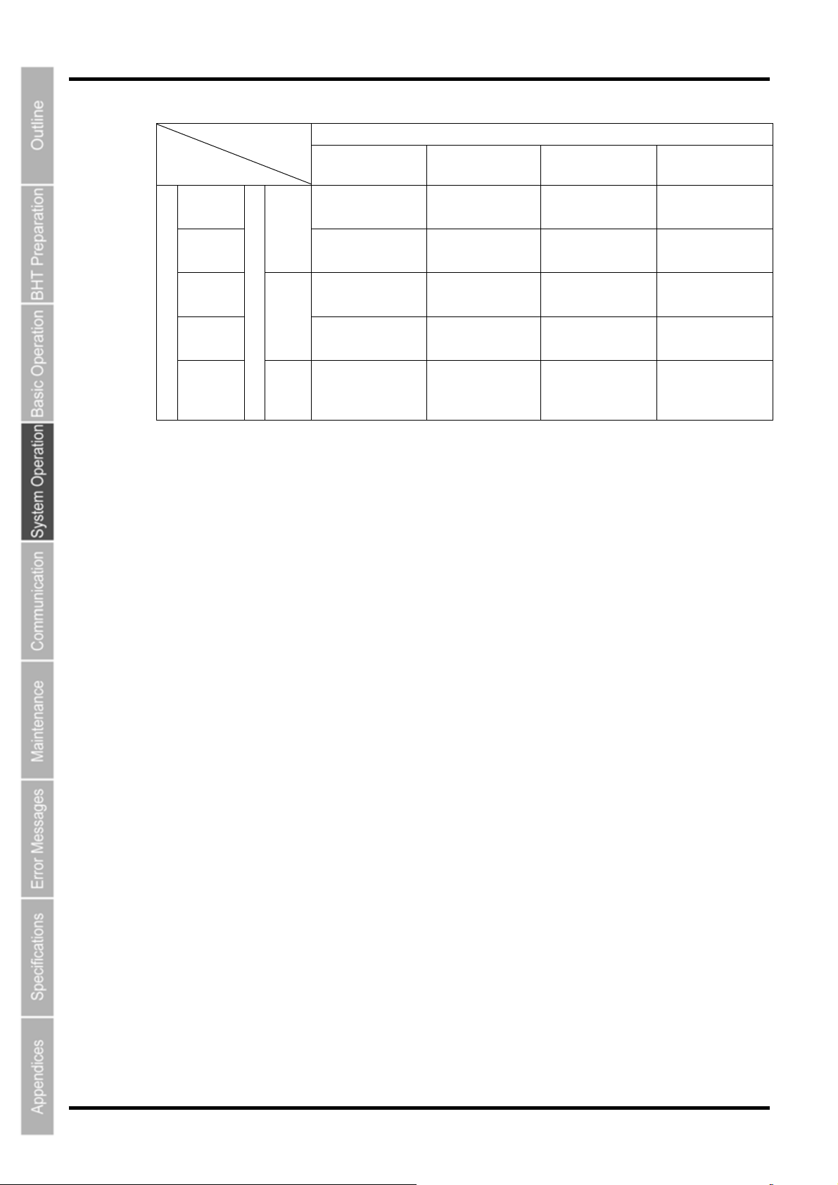
BHT-805B
Standard
font
Small
font
BHT-805B
ANK
mode
BHT-300
Mode
22 x 16 char.
(10 x 20 dots)
22 x 21 char.
(10 x 15 dots)
BHT-7500
Mode
26 x 26 char.
(9 x 12 dots)
26 x 26 char.
(9 x 12 dots)
BHT-100
Mode
20 x 26 char.
(12 x 12 dots)
20 x 26 char.
(12 x 12 dots)
Normal
Mode
20 x 20 char.
(12 x 16 dots)
20 x 20 char.
(12 x 16 dots)
Standard
font
Font size
Small
font
Kanji
mode
Screen mode
Redu
ced
Kanji
8 x 8 char.
(28 x 40 dots)
11 x 10 char.
(20 x 30 dots)
11 x 8 char.
(20 x 40 dots)
10 x 13 char.
(24 x 24 dots)
13 x 17 char.
(18 x 18 dots)
(Not supported) (Not supported) (Not supported)
15 x 20 char.
(16 x 16 dots)
20 x 26 char.
(12 x 12 dots)
8 x 10 char.
(30 x 30 dots)
10 x 13 char.
(24 x 24 dots)
68
Page 82
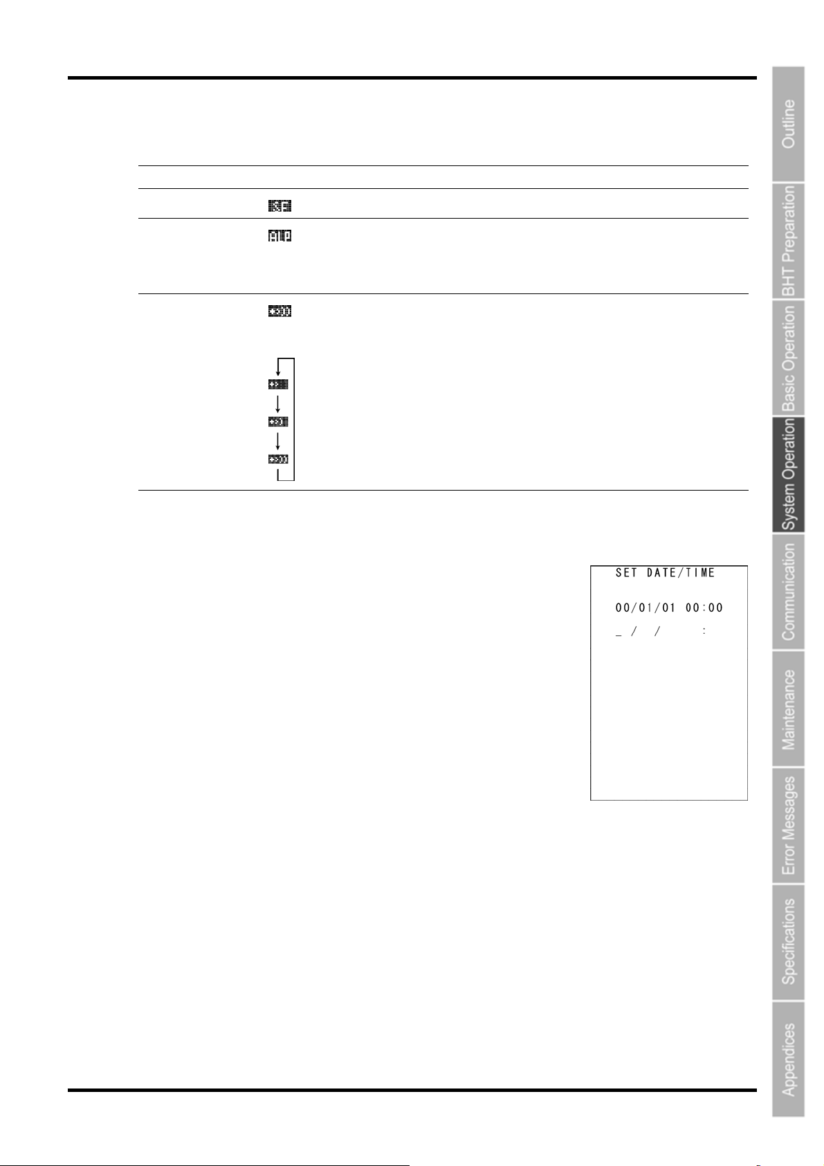
Barcode Handy Terminal
System Status Indication
Turning ON the system status indication displays the following icons at the bottom of the screen.
Indication Icon Description
Key Shift status
Alphabet
entry mode
Communication link
with the CU-811
Displays when the keys on the keypad are in Shift mode.
Displays when the BHT is set to alphabet entry mode.
(If the alphanumeric entry system has been selected in user programs,
pressing the SF key switches from the numeric entry mode to alphabet
entry mode.)
Displays when a communication link is established with the CU-811.
Flashes when the BHT tries to communicate with a CU-811 that has not
been linked with the BHT.
Displays cyclically when the BHT receives no response from the
CU-811, or when it is waiting for the link to be established with or
severed from the CU-811.
[3] Setting the calendar clock
When resetting the date and time, refer to “Chapter 2 BHT Preparation” “2.4 Initial Setup.”
Select ”3: DATE/TIME” at the SET SYSTEM menu and press the ENT key
to display the SET DATE/TIME menu screen on the right.
69
Page 83
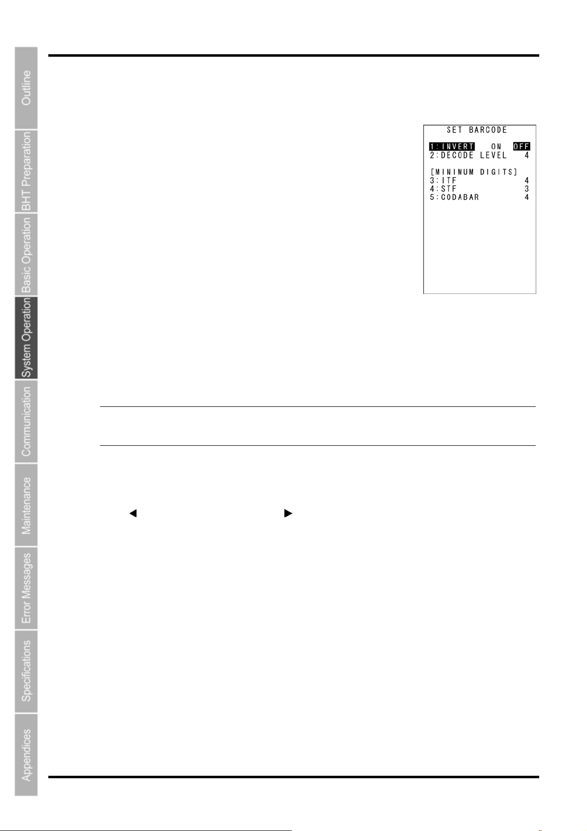
BHT-805B
[4] Setting the special barcode reading parameters
Use the following procedure to set the barcode reading conditions.
1. Select “4: BARCODE” at the SET SYSTEM menu and then press the
ENT key.
The SET BARCODE menu screen on the right displays.
The highlighted display and displayed values will be the current settings.
2. Use the cursor keys ([▲] [▼]) or numerical keys ([1] [2] [3] [4] [5]) to
highlight the item to be set.
3. Change settings with the cursor keys ([◄] [►]) and press the ENT
key.
Press the BS/C key to return to the SET SYSTEM menu.
“1: INVERT”: Black/white inverted label reading function
Enable or disable black/white inverted label reading.
“ON”: Enables black/white inverted label reading.
“OFF”: Disables black/white inverted label reading.
- Point - By enabling black/white inverted label reading, it will also be possible to read black/white
inverted labels, however, there is higher chance of barcodes being incorrectly read.
This should normally be set to “OFF” (black/white inverted label reading disabled).
“2: DECODE LEVEL”: Decode level
Set the decode level (barcode reading tolerance level).
Press [
Decreasing the level increases the barcode reading efficiency, however, the BHT may incorrectly read
low-quality (split or stained) barcodes.
On the other hand, increasing the level decreases the barcode reading efficiency, but will decrease the
possibility of incorrect reading.
] to decrease the setting value and [ ] to increase the setting value.
Decode level entry range: 1 - 9(Default: 4)
70
Page 84
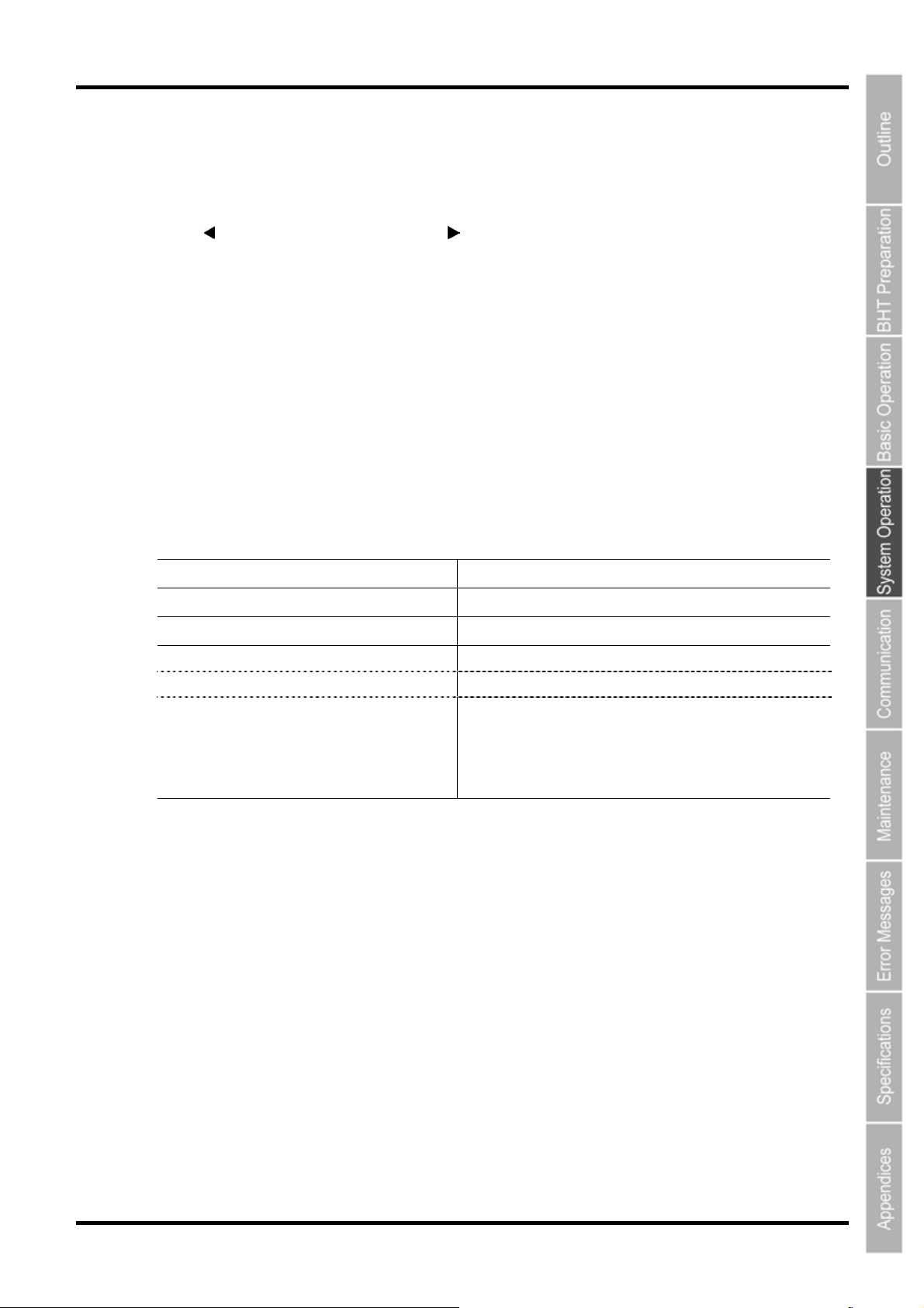
Barcode Handy Terminal
“3: ITF”: Minimum number of digits to be read for ITF
“4: STF”: Minimum number of digits to be read for STF
“5: CODABAR”: Minimum number of digits to be read for Codabar
Set minimum number of digits for the code to be read.
Press [
Setting a small number of digits increases the frequency of missing digits when reading, or incorrectly
reading depending on how barcodes are read, or the quality of barcodes. On the other hand, setting a
large number will decrease the possibility of such errors.
[5] Setting the communication environment
The communication environment settings following system initialization are follows.
Do not change these settings unless necessary.
] to decrease the setting value and [ ] to increase the setting value.
ITF entry range: 2 - 20(Default: 4)
STF entry range: 1 - 20(Default: 3)
Codabar entry range: 3 - 20(Default: 4)
Item Default
Interface port Optical (IrDA interface port)
Communication protocol Ymodem protocol
IrDA interface port
TRANSMIT SPEED Baud rate 115200 bps
PROTOCOL Protocol options SERIAL No.: ON (Adds serial numbers to data
blocks.
H. PARITY: ON (
LINKUP TIME: 30
FIELD SPACE: Ignore (
Adds horizontal parity.)
seconds
)
Trim)
71
Page 85
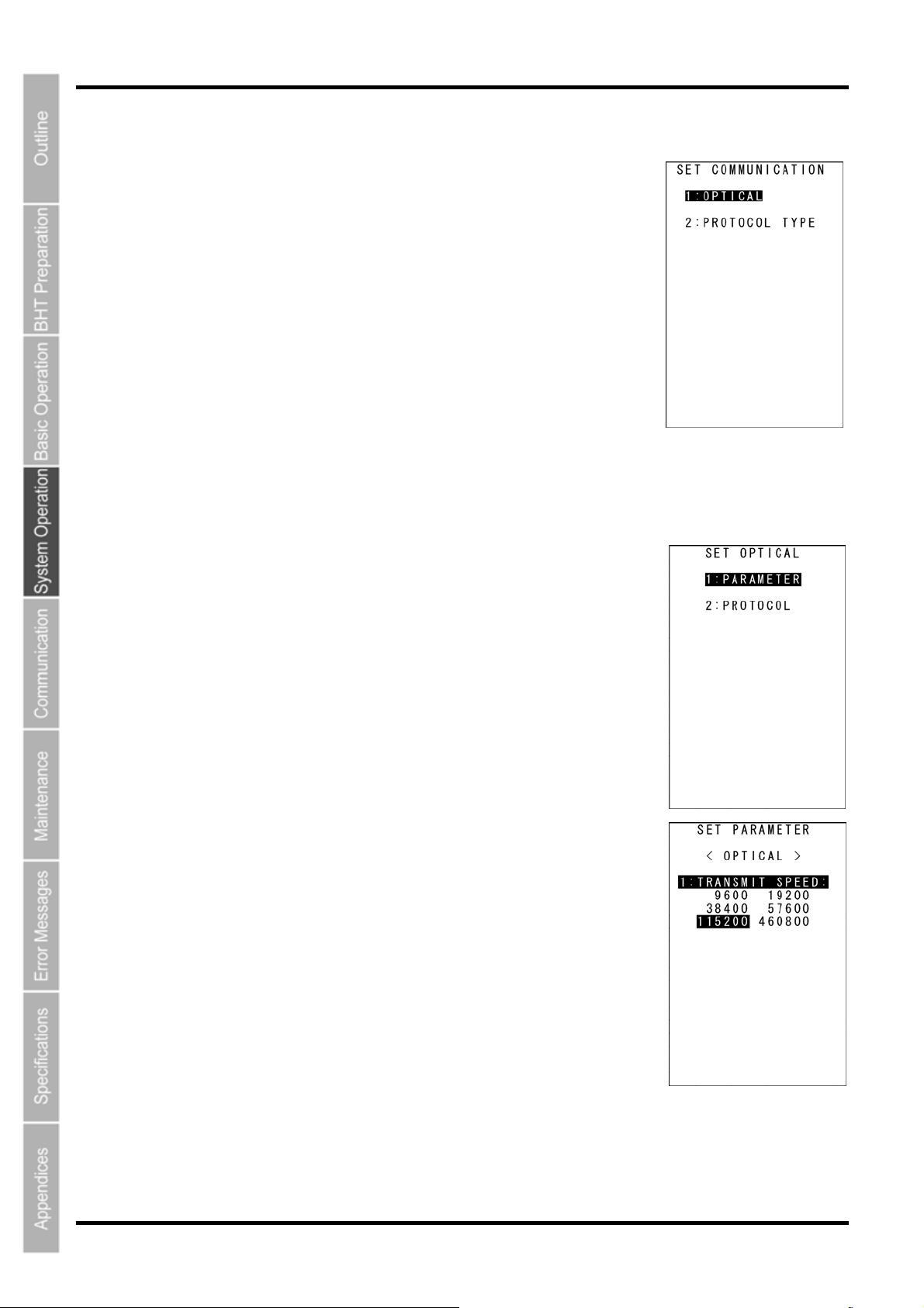
BHT-805B
Use the following procedure if necessary to change the communication environment settings.
1. Select “5: COMMUNICATION” at the SET SYSTEM menu and then
press the ENT key.
The SET COMMUNICATION menu screen on the right displays.
2. Use the cursor keys ([▲] [▼]) or numerical keys ([1] [2] [3] [4]) to
highlight the item to be set and press the ENT key.
“1: OPTICAL”:
Changes the IrDA communication parameters.
“2: PROTOCOL TYPE”:
Changes the communication protocol setting.
Refer to the following section for details of the above items.
Press the BS/C key to return to the SYSTEM MENU.
“1: OPTICAL”: IrDA communication parameters
1. Select “1: OPTICAL” at the SET COMMUNICATION menu and then
press the ENT key.
The SET OPTICAL menu screen on the right displays.
2. Use the cursor keys ([▲] [▼]) or numerical keys ([1] [2]) to
highlight ”1: PARAMETER” or ”2: PROTOCOL”, and then press the
ENT key.
Press the BS/C key to return to the SET SYSTEM menu.
“1: PARAMETER”: Setting the communication parameters
Select “1: PARAMETER” to display the screen shown on the right.
The highlighted setting will be the current setting.
“1: TRANSMIT SPEED”: Setting the transmission speed
To change the setting, highlight the transmission speed with the cursor
keys ([◄] [►]) and press the ENT key.
Press the BS/C key to return to the OPTICAL menu.
72
Page 86
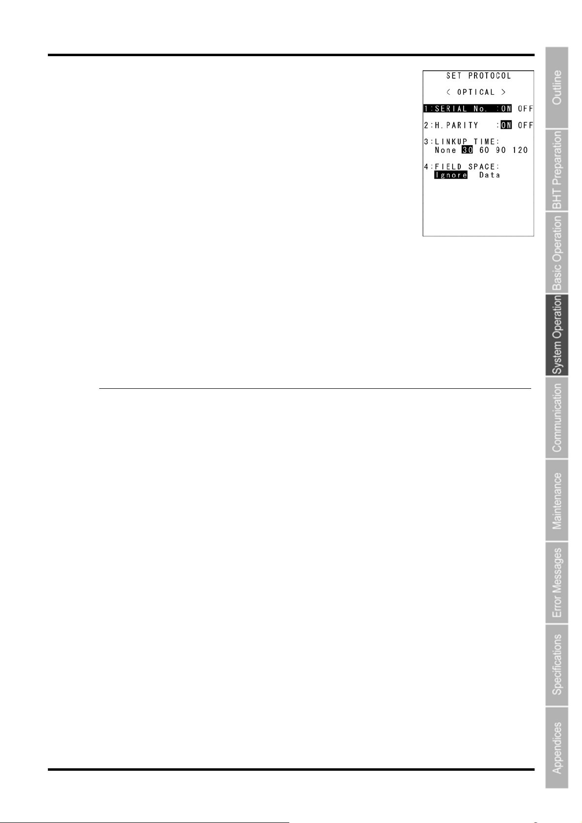
Barcode Handy Terminal
“2: PROTOCOL”: Communication protocol options setting screen
Select “2: PROTOCOL” to display the screen shown on the right
The highlighted settings will be the current settings.
“1: SERIAL No.”:
Selects whether or not to add serial numbers to data blocks.
“2: H.PARITY”:
Selects whether or not to add horizontal parity.
“3: LINKUP TIME”:
Selects the timeout length (in seconds) to be applied when a link is to be
established.
“4: FIELD SPACE”:
Specifies handling for trailing spaces in fields.
To trim trailing spaces in fields, select “Ignore”, and to retain them as data, select “Data”.
To make changes, use the cursor keys ([▲] [▼]) or numerical keys ([1] [2] [3] [4]) to highlight the item to
be set, highlight the setting value using the cursor keys ([◄] [►]), and then press the ENT key.
Press the BS/C key to return to the SET OPTICAL menu.
- Point - Selecting the BHT-Ir or YMODEM protocol ignores the serial number and horizontal parity
settings.
73
Page 87
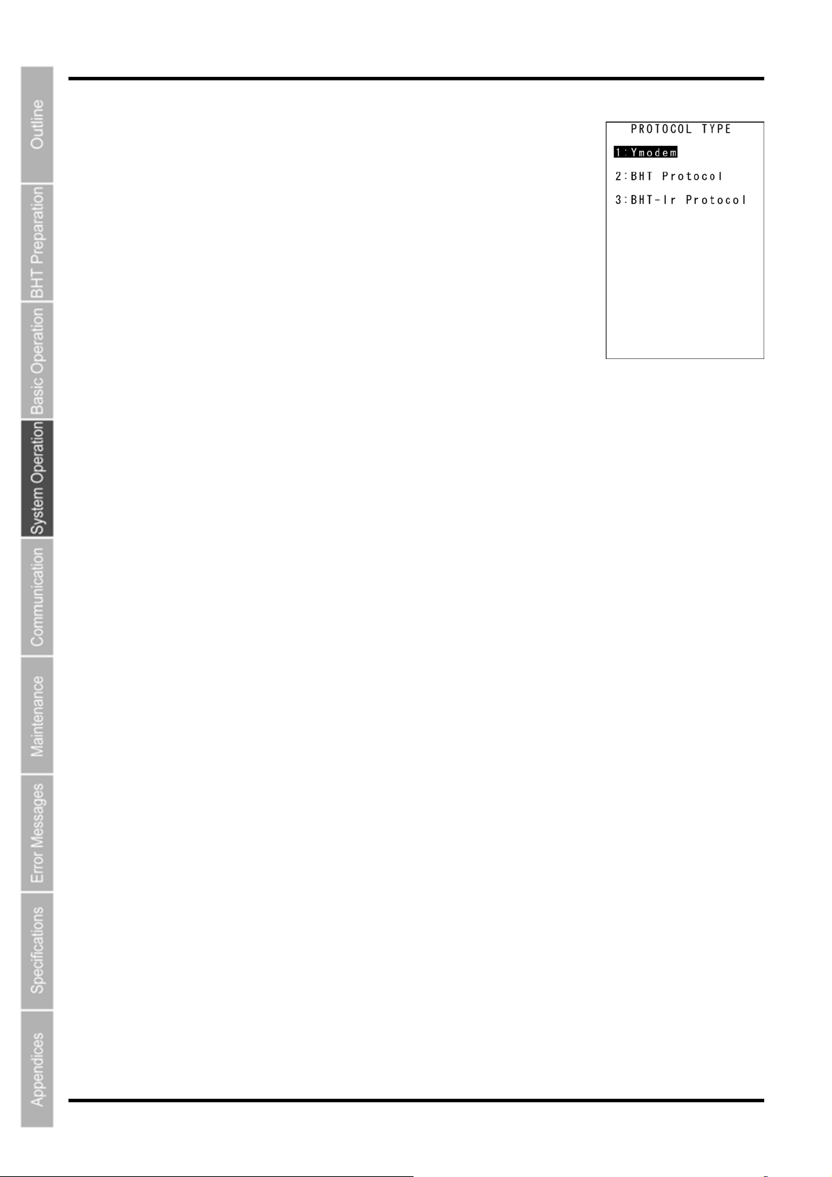
BHT-805B
“
“2: PROTOCOL TYPE”: Setting the communication protocol
type
1. Select “2: PROTOCOL TYPE” at the SET COMMUNICATION menu
and then press the ENT key.
The PROTOCOL TYPE menu screen on the right displays.
The highlighted setting will be the current setting.
“1: Ymodem”:
Selects Ymodem when uploading/downloading in System Mode or for
the execution of the XFILE statement in BHT-BASIC.
“2: BHT Protocol”:
Selects the BHT-protocol when uploading/downloading in System Mode
or for the execution of the XFILE statement in BHT-BASIC.
“3: BHT-Ir Protocol”:
Selects the BHT-Ir protocol when uploading/downloading in System Mode or for the execution of the
XFILE statement in BHT-BASIC.
To make changes, use the cursor keys ([▲] [▼]) or numerical keys ([1] [2] [3]) to highlight the setting item,
and then press the ENT key.
To use the BHT-BASIC 4.0 Transfer Utility, select Ymodem or BHT-Ir protocol.
Press the BS/C key to return to the SET COMMUNICATION menu.
74
Page 88
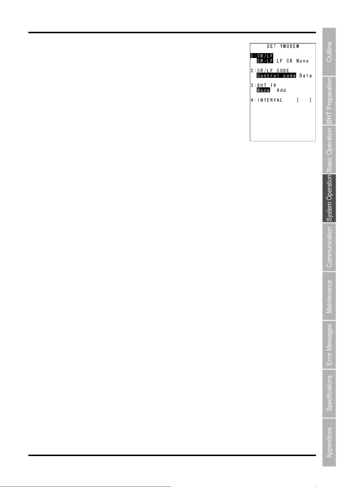
Barcode Handy Terminal
Select “1: Ymodem” at the PROTOCOL TYPE menu to display the screen
on the right.
The highlighted settings will be the current settings.
“1: CR/LF”:
Specifies line delimiters.
“2: CR/LF CODE”:
Specifies handling for line delimiters in records when data files are
downloaded.
“Control code”:
Does not handle line-break codes as data.
(Handles as record delimiters.)
“Data”:
Handles line-break codes as data.
“3: BHT ID”:
Specifies whether or not to add the BHT ID number to packets when performing YMODEM transfer.
“None” should normally be selected. To add the BHT ID number to the transfer tool, select “Add”. (This
setting is not supported. Changing this setting has no result.)
“4: INTERVAL”:
Specifies the retry interval within a range of 1 to 255 in units of 100 ms.
To make changes, use the cursor keys ([▲] [▼]) or numerical keys ([1] [2] [3] [4]) to highlight the item to
be set, highlight the setting value using the cursor keys ([◄] [►]), and then press the ENT key.
For “4: INTERVAL”, press the ENT key to change to entry mode.
The cursor displays, allowing the previous setting to be deleted by pressing the BS/C key.
Enter a new setting value with the numerical keys and press the ENT key.
Press the BS/C key to return to the SET COMMUNICATION menu.
75
Page 89
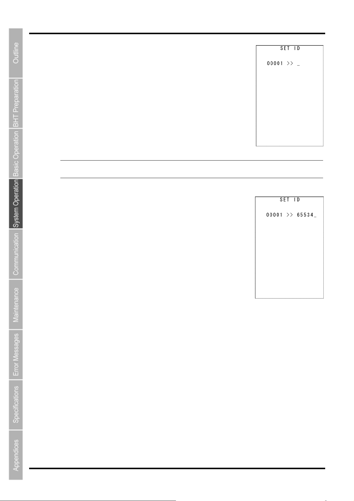
BHT-805B
Select “3: BHT-Ir Protocol” at the PROTOCOL TYPE menu to display the
screen on the right.
Enter the ID number of the BHT using the numerical keys and then press
the ENT key. If there is no need to edit the current setting, press the ENT
key only.
If an incorrect entry is made, press the BS/C key to delete it and then enter
the correct data.
Press the BS/C key to return to the SET COMMUNICATION menu.
- Point - ID numbers should consist of a five-digit decimal character string. The entry range is from
00001 to 65534. If the entry value is less than five digits, the ENT key will be invalid.
76
Page 90
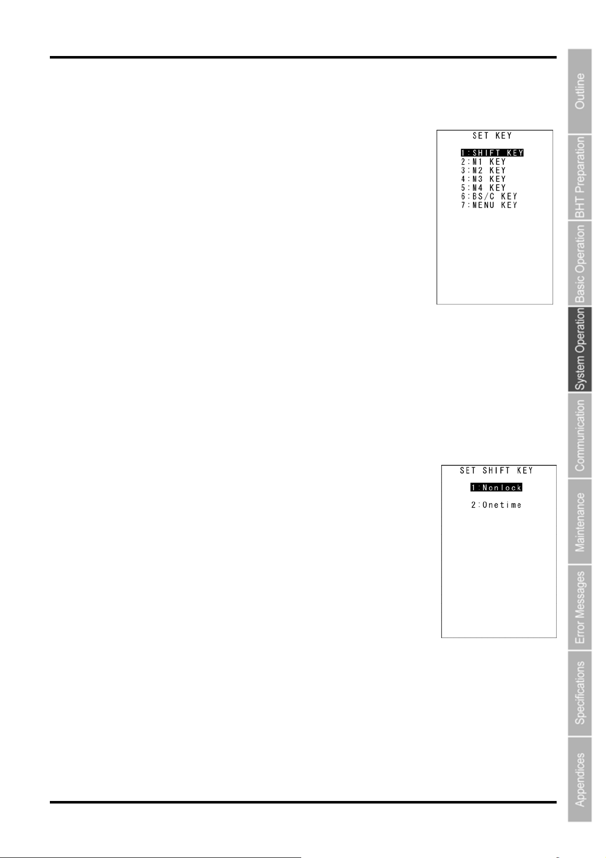
Barcode Handy Terminal
[6] Defining the functions of the Shift key and Magic keys
Use the following procedure to change the key settings.
1. Select “6: KEY” at the SET SYSTEM menu and then press the ENT
key.
The SET KEY menu screen on the right displays.
2. Use the cursor keys ([▲] [▼]) or numerical keys ([1] [2] [3] [4] [5] [6]
[7]) to highlight the item to be set, and then press the ENT key.
“1: SHIFT KEY”: Displays the SF key definition screen.
“2: M1 KEY”: Displays the M1 key definition screen.
“3: M2 KEY”: Displays the M2 key definition screen.
“4: M3 KEY”: Displays the M3 (left-hand trigger
switch) key definition screen.
“5: M4 KEY”: Displays the M4 (right-hand trigger
switch) key definition screen.
“6: BS/C KEY”: Displays the BS/C key definition screen.
“7: MENU KEY”: Displays the M1-M4 key menu definition screen.
Refer to the following section for details of the above items.
Press the BS/C key to return to the SET SYSTEM menu.
“1:SHIFT KEY”: Defining the Shift key function
1. Select “1: SHIFT KEY” at the SET KEY menu and then press the
ENT key.
The SET SHIFT KEY menu screen on the right displays.
The highlighted setting will be the current setting.
“1: Nonlock”: Shifts the keypad only when the SF key is held down.
“2: Onetime”: Shifts only the key pressed immediately after the SF
key is pressed. (The following keys will not be shifted.)
2. Use the cursor keys ([▲] [▼]) or numerical keys ([1] [2]) to highlight
the item to be set, and then press the ENT key.
The selected item will be set and the screen will return to the SET KEY menu.
77
Page 91
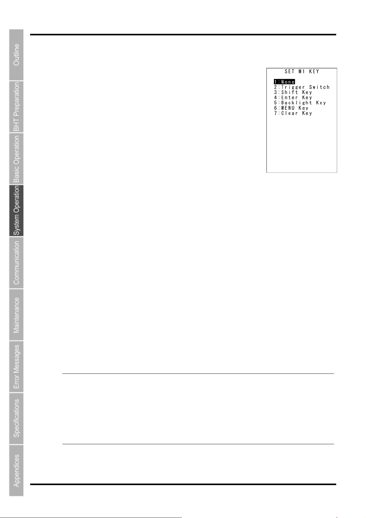
BHT-805B
“2: M1 KEY” - ”5: M4 KEY”: Defining the Mx key functions
1. Select “2: M1 KEY” to “5: M4 KEY” at the SET KEY menu and then
press the ENT key.
The SET Mx KEY menu screen on the right displays.
(In the example on the right, “2: M1 KEY” has been selected.)
The highlighted setting will be the current setting.
“1: None”:
Key entry will be ignored.
“2: Trigger Switch”:
Sets the magic key as the trigger switch.
“3: Shift Key”:
Sets the magic key as the SF key.
“4: Enter Key”:
Sets the magic key as the ENT key.
“5: Backlight Key”:
Sets the magic key as the backlight function ON/OFF key.
“6: MENU”:
Sets the magic key as a key used to start up the “Speaker/Vibrator/Backlight Adjustment Screen”.
“7: Clear Key”:
Sets the magic key as the C key.
2. Use the cursor keys ([▲] [▼]) or numerical keys ([1] [2] [3] [4] [5] [6] [7]) to highlight the item to
be set, and then press the ENT key.
The selected item will be set and the screen will return to the SET KEY menu.
Magic keys (M1 to M4)
Magic keys (M1 to M4) can be set to function as the trigger switch, SF key, ENT key, backlight function
ON/OFF key, MENU key or BS/C key.
If the M1 key is defined as the backlight function ON/OFF key, pressing the M1 key enables or disables
the backlight function.
In user programs, data strings can be also assigned to these magic keys.
Magic keys M3 and M4 are set as the trigger switch by default.
- Point -
The backlight function ON/OFF key can be assigned only to one of the magic keys from M1
to M4. The key defined more recently will act as the backlight function ON/OFF key and the
previously defined key will be ignored.
If, for example, the M1 and M2 keys are defined as the backlight function ON/OFF key in this
order, the M2 key will function as the backlight function ON/OFF key and the M1 key entry
will be ignored.
On the other hand, if the M2 and M1 keys are defined as the backlight function ON/OFF key
in this order, the M1 key will function as the backlight function ON/OFF key and the M2 key
entry will be ignored.
78
Page 92
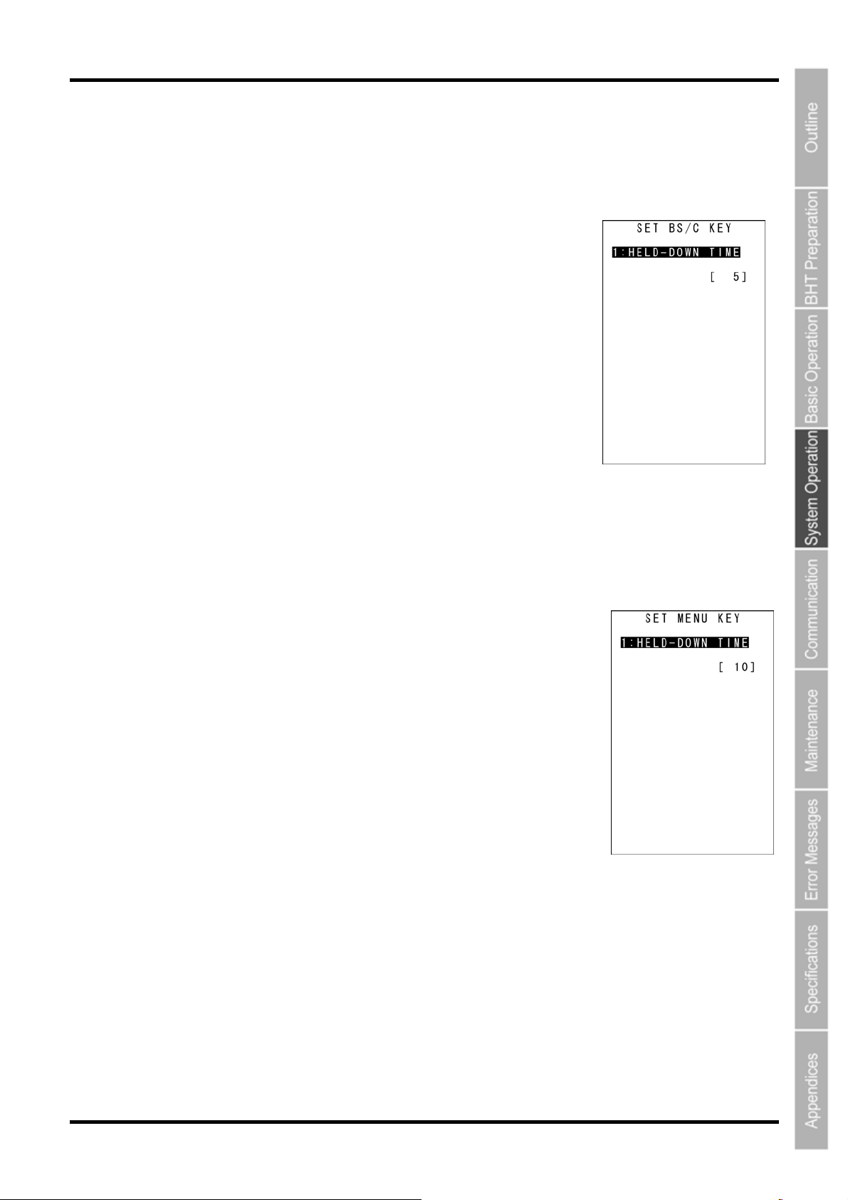
Defining the backspace/clear key (BS/C key) function
The BS/C key deletes the last entered character (backspace), and when pressed and held,
cancels entry and returns the LCD display to the previous screen (clear). This menu sets the
key hold time for “clear”.
1. Select “6: BS/C KEY” at the SET KEY menu, and then press the
ENT key.
The highlighted setting will be the current setting.
2. Press the ENT key to display the cursor.
3. Press and hold the BS/C key to clear all of the current settings.
4. Enter the desired numeric values.
Numeric values can be entered between 1 and 255 (x 100 ms.)
Barcode Handy Terminal
5. Press the ENT key.
Defining the MENU key setting
The M1 to M4 keys can be set as menu keys. When M1 to M2 set as menu
keys are pressed and held, the menu screen is displayed. This menu sets the
key hold time.
1. Select “7: MENU KEY” at the SET SYSTEM menu and then press
the ENT key.
The highlighted setting will be the current setting.
2. Press the ENT key to display the cursor.
3. Press and hold the BS/C key to clear all of the current settings.
4. Enter the desired numeric values.
Numeric values can be entered between 1 and 255 (x 100 ms.)The screen displays as shown
on the right
5. Press the ENT key.
79
Page 93
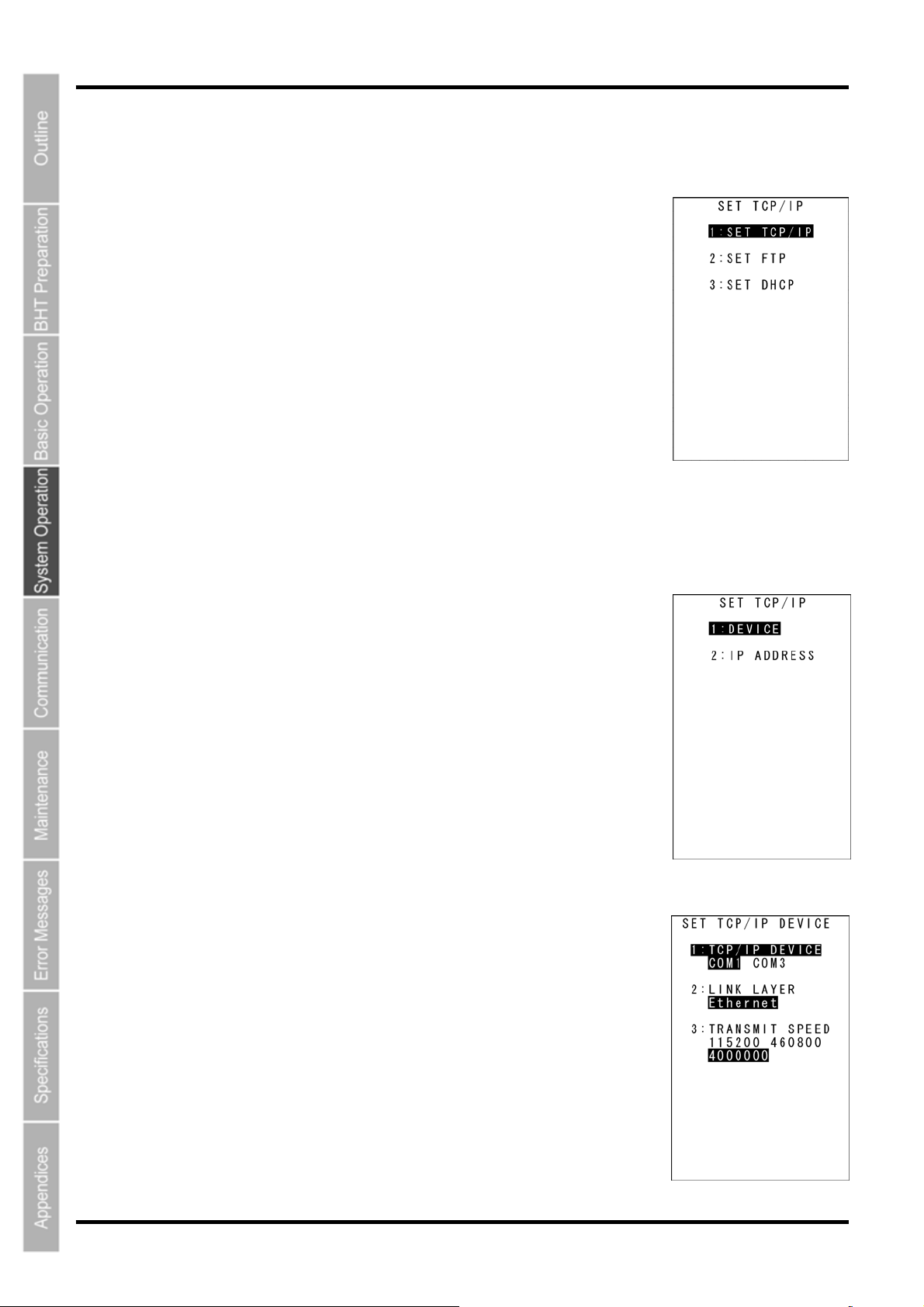
BHT-805B
[7] SettingtheTCP/IP,FTPandDHCP
Use the following procedure to change the TCP/IP, FTP and DHCP settings.
1. Select “7: TCP/IP” at the SET SYSTEM menu and then press the
ENT key.
The SET TCP/IP menu screen on the right displays.
2. Use the cursor keys ([▲] [▼]) or numerical keys ([1] [2] [3]) to
highlight the item to be set, and then press the ENT key.
“1: SET TCP/IP”: Changes the TCP/IP setting.
“2: SET FTP”: Changes the FTP setting.
“3: SET DHCP”: Changes the DHCP setting.
Refer to the following section for details of the above items.
Press the BS/C key to return to the SET SYSTEM menu.
“1: SET TCP/IP”: Setting the TCP/IP
1. Select “1: SET TCP/IP” at the SET TCP/IP menu and then press the
ENT key.
The SET TCP/IP menu screen on the right displays.
2. Use the cursor keys ([▲] [▼]) or numerical keys ([1] [2]) to highlight
the item to be set, and then press the ENT key.
Press the BS/C key to return to the SET TCP/IP menu.
“1: DEVICE”: Setting the TCP/IP device
Select “1: DEVICE” at the SET TCP/IP menu to display the screen on the
right where the current settings are displayed.
“1: TCP/IP DEVICE”: TCP/IP communication device
“2: LINK LAYER”: Link layer
“3 TRANSMIT SPEED”: Communication speed with CU
Press the BS/C key to return to the SET TCP/IP menu.
80
Page 94
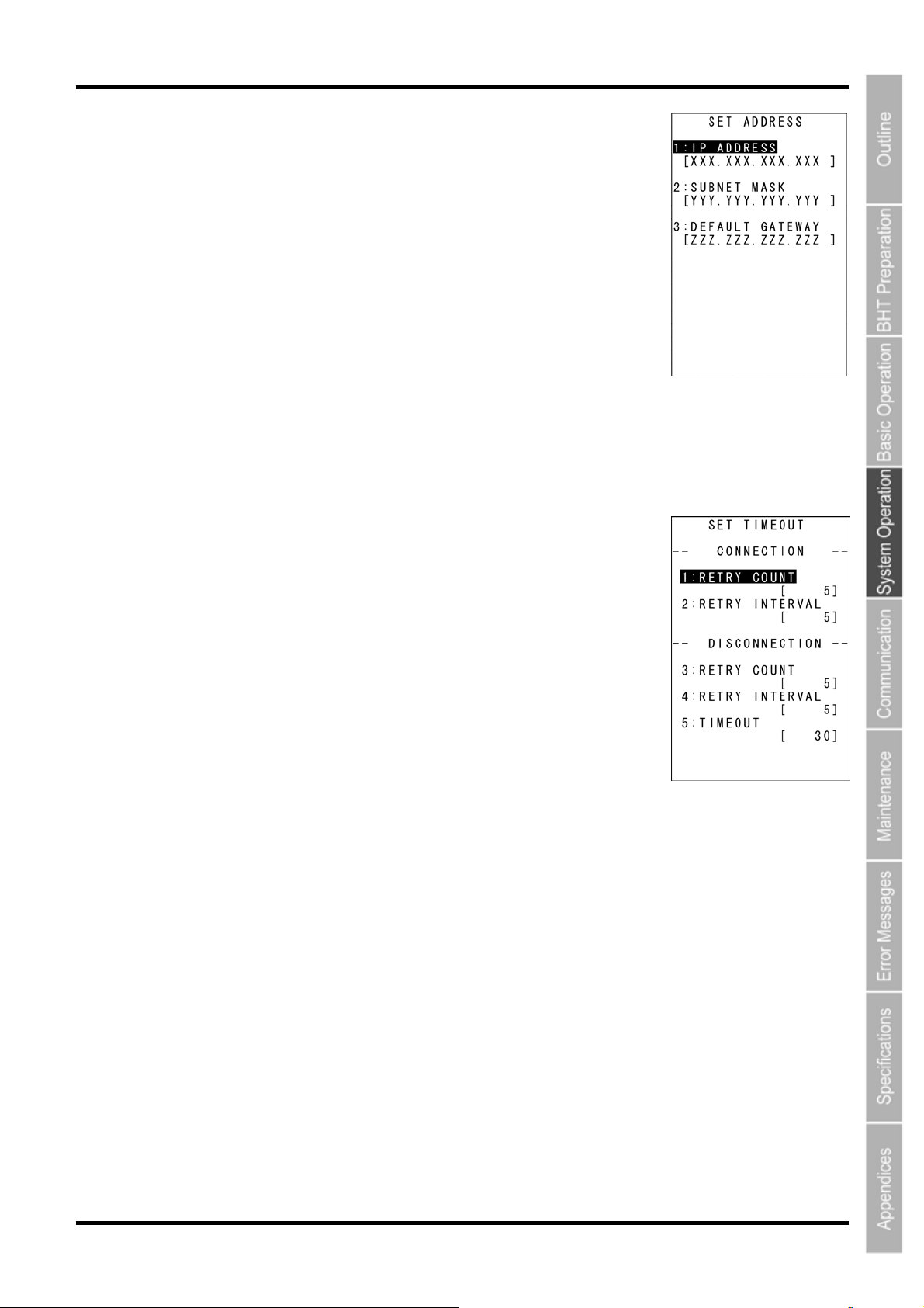
Barcode Handy Terminal
“2: IP ADDRESS”: Setting the IP address
Select “2: IP ADDRESS” at the SET TCP/IP menu to display the screen on
the right where the current settings are displayed.
To change the setting:
(1) Use the cursor keys ([▲] [▼]) or numerical keys ([1] [2] [3]) to highlight
the item to be set and press the ENT key.
(2) The mode changes to entry mode and the cursor displays, allowing the
setting to be entered with the numerical keys and dot key.
To delete a single character, press the BS/C key. To delete the entire
entry, press and hold the BS/C key, or press the SF key and BS/C key
simultaneously.
(3) Enter the desired value and then press the ENT key.
If the IP address, subnet mask and default gateway are all set to [0.0.0.0], DHCP is enabled.
Press the BS/C key to return to the SET TCP/IP menu.
“3: TIMEOUT”: Setting the timeout (only when COM1 selected)
Select “3: TIMEOUT” at the SET TCP/IP menu to display the screen on the
right where the current settings are displayed.
To change the setting:
(1) Use the cursor keys ([▲] [▼]) or numerical keys ([1] [2] [3] [4] [5]) to
highlight the item to be set and press the ENT key.
(2) The mode changes to entry mode and the cursor displays, allowing the
setting to be entered with the numerical keys and dot key.
To delete a single character, press the BS/C key. To delete the entire
entry, press and hold the BS/C key, or press the SF key and BS/C key
simultaneously.
(3) Enter the desired value, and then press the ENT key.
Press the BS/C key to return to the SET TCP/IP menu.
81
Page 95
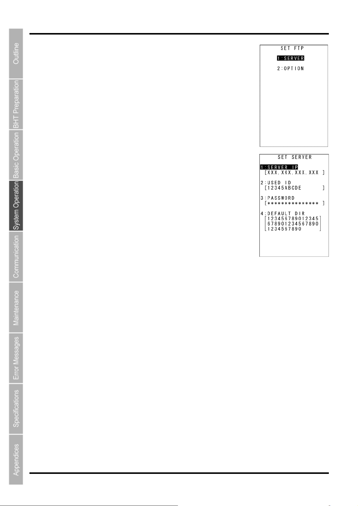
BHT-805B
Setting the FTP
1. Select “2: SET FTP” at the SET TCP/IP menu and then press the
ENT key.
The SET FTP menu screen on the right displays.
2. Use the cursor keys ([▲] [▼]) or numerical keys ([1] [2]) to highlight
the item to be set, and then press the ENT key.
Press the BS/C key to return to the SET TCP/IP menu.
“1: SERVER”: Setting the FTP server connection environment
Select “1: SERVER” at the SET FTP menu to display the screen on the right
where the current settings are displayed.
“1: SERVER IP”:
Sets the IP address for the FTP server.
“2: USER ID”:
Sets the user name.
“3: PASSWORD”:
Sets the password.
“4: DEFAULT DIR”:
Specifies an initial directory through which the FTP server will
search for files for transfer first when the FTP client establishes a
connection to the server.
To change the setting:
(1) Use the cursor keys ([▲] [▼]) or numerical keys ([1] [2] [3] [4]) to
highlight the item to be set and press the ENT key.
(2) The mode changes to entry mode and the cursor displays, allowing the
setting to be entered with the numerical keys and dot key.
Press the SF key to change the entry mode [numeric entry
(with no guidance display) and alphabet entry].
To delete a single character, press the BS/C key. To delete the entire entry,
press and hold the BS/C key, or press the SF key and BS/C key simultaneously.
(3) Enter the desired value, and then press the ENT key.
Press the BS/C key to return to the SET FTP menu.
82
Page 96
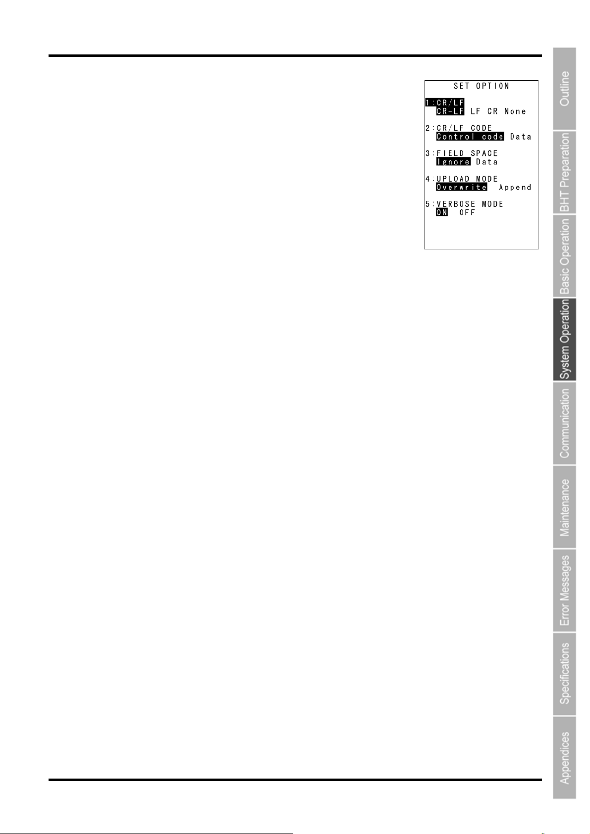
Barcode Handy Terminal
“2: OPTION”: Setting the FTP options
Select “2: OPTION” at the SET FTP menu to display the screen on the right
where the current settings are displayed.
“1: CR/LF”:
Specifies line delimiters that should match ones used in the server OS.
“2: CR/LF CODE”:
Specifies the treatment of line delimiters in records when data files are
downloaded.
“Control code”: Does not handle line-break codes as data.
(Handles as record delimiters.)
“Data”: Handles line-break codes as data.
“3: FIELD SPACE”:
Specifies the treatment of trailing spaces in fields.
“Ignore”: Trims trailing spaces in fields.
“Data”: Retains trailing spaces as data.
“4: UPLOAD MODE”:
Specifies handling for trailing spaces in fields.
”Overwrite”: Uploaded files will be written over the existing files
“Append”: Uploaded files will be appended to the existing files.
“5: VERBOSE MODE”:
Specifies the command response display when using FTP.
“ON”: Displays a message to the response (number) from the FTP server when the BHT (FTP
client) outputs a message.
“OFF”: Displays only messages output by the BHT (FTP client).
Refer to “FTP Download/Upload Messages” at section “4.5.9 Downloading/Uploading Files by FTP (FTP
MENU)” for messages output by the BHT (FTP client).
Refer to “Response Messages from the FTP Server” at section “4.5.9 Downloading/Uploading Files by
FTP (FTP MENU)” for messages to responses (numbers) from the FTP server.
To change the setting:
(1) Use the cursor keys ([▲] [▼]) or numerical keys ([1] [2] [3] [4] [5]) to
highlight the item to be set and press the ENT key.
(2) Use the cursor keys ([◄] [►]) to highlight each setting value.
(3) Press the ENT key.
Press the BS/C key to return to the SET FTP menu.
83
Page 97
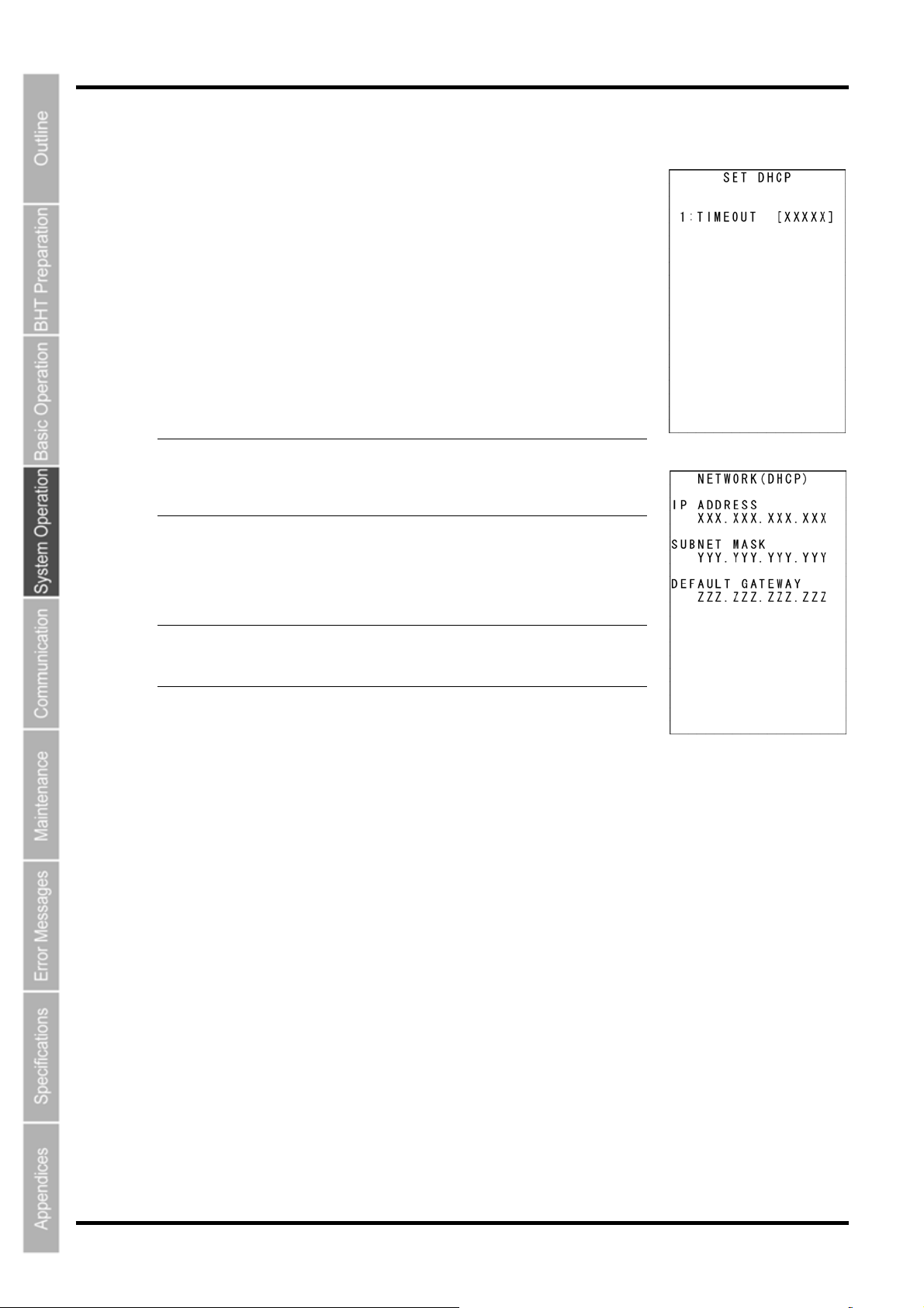
BHT-805B
f
Setting the DHCP
1. Select “3: DHCP” at the SET TCP/IP menu and then press the ENT
key.
The SET DHCP screen on the right displays.
The highlighted setting will be the current setting.
Press the BS/C key to return to the SET TCP/IP menu.
Press the dot key while holding down the SF key at the SET DHCP menu to
display the NETWORK (DHCP) screen (acquisition check screen for IP
address at DHCP).
Press the BS/C key at the NETWORK (DHCP) screen to return to the SET
DHCP screen.
- Point - If the acquired IP configuration is displayed when the IP
address, subnet mask or default gateway is set to a value
other than ”0.0.0.0”, the DHCP does not display on the screen
shown on the right.
BS/C key / SF key + [.] key
“1: TIMEOUT”:
Sets the timeout for acquiring the IP configuration from the DHCP
server. The entry range is from 00001 to 32767 seconds.
- Point - Up to 32767 seconds can be entered, but in actual operation,
To set the DHCP:
(1) Press the ENT key.
(2) The mode changes to entry mode and the cursor displays, allowing the
setting to be entered with the numerical keys.
To delete a single character, press the BS/C key. To delete the entire entry,
press and hold the BS/C key, or press the SF key and BS/C key simultaneously.
(3) Enter the desired value, and then press the ENT key.
Press the BS/C key to return to the SET FTP menu.
a maximum of 190 seconds is available since the number o
retries and retry intervals are determined by the system.
84
Page 98
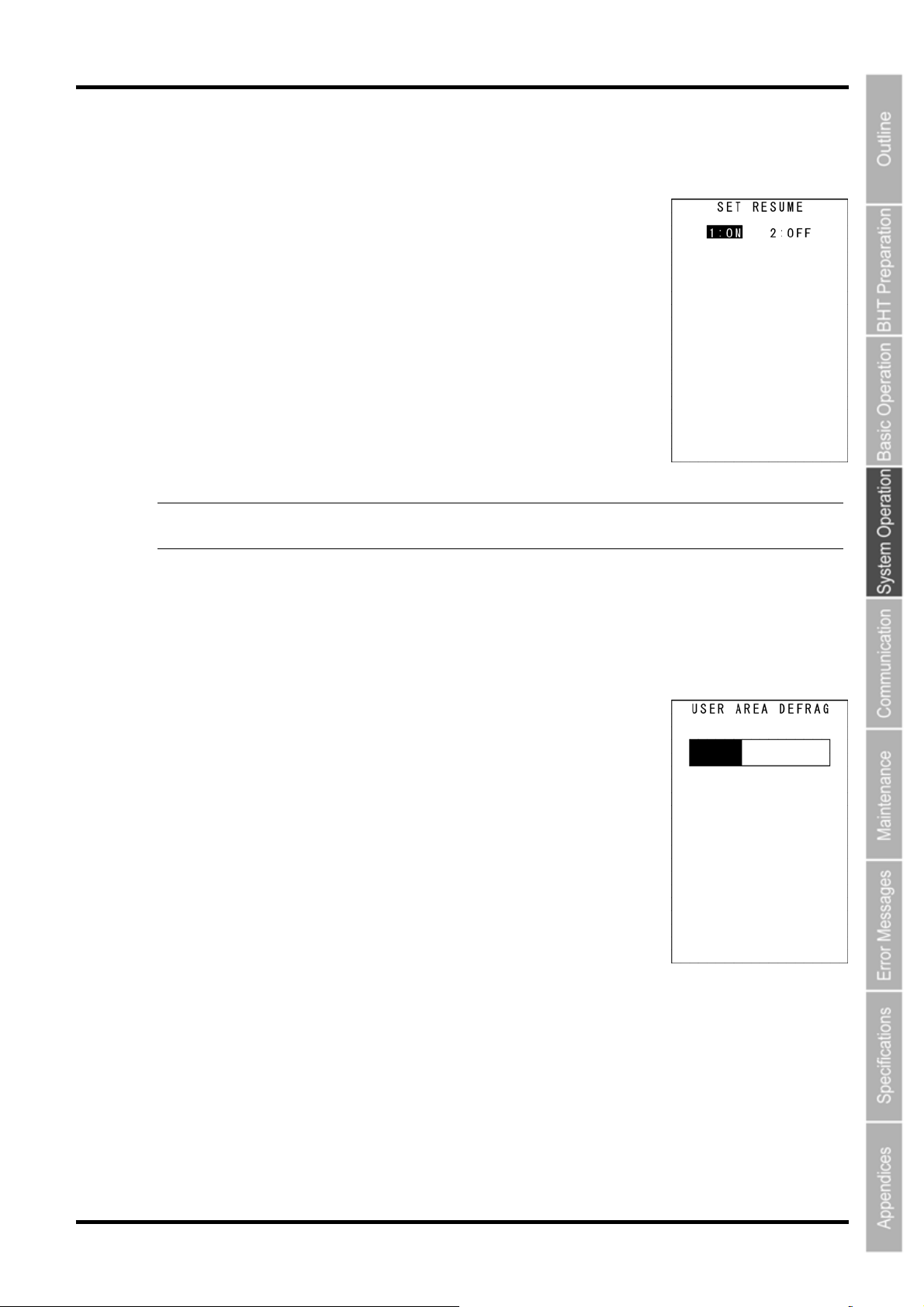
Barcode Handy Terminal
[8] Setting the resume function
Use the following procedure to set the resume function.
1. Select “1: RESUME” from the SET SYSTEM Menu 2/2 and then
press the ENT key.
The SET RESUME screen on the right displays.
The highlighted setting will be the current setting.
2. Use the cursor keys ([▲] [▼]) or numerical keys ([1] [2]) to change
the setting, and then press the ENT key.
Press the BS/C key to return to the SET SYSTEM Menu.
1:ON: Enables the resume function.
2:OFF: Disables the resume function.
-Point- When the power is turned ON, the resume function starts the BHT from the position in the
program (screen) where the BHT power was last turned OFF.
[9] defragging the drive
Use the following procedure to perform drive defrag.
1. Select “2: DEFRAG” from the SET SYSTEM Menu 2/2 and then
press the ENT key.
The screen displays as shown on the right and the defragmentation process
is
performed for the entire user area.
The screen returns to the SYSTEM MENU when defragmentation is
complete.
Defragmentation reorganizes the user area in order to increase the amount
of available space.
If defragmented, the BHT may download files more efficiently than before
performing defragmentation.
85
Page 99
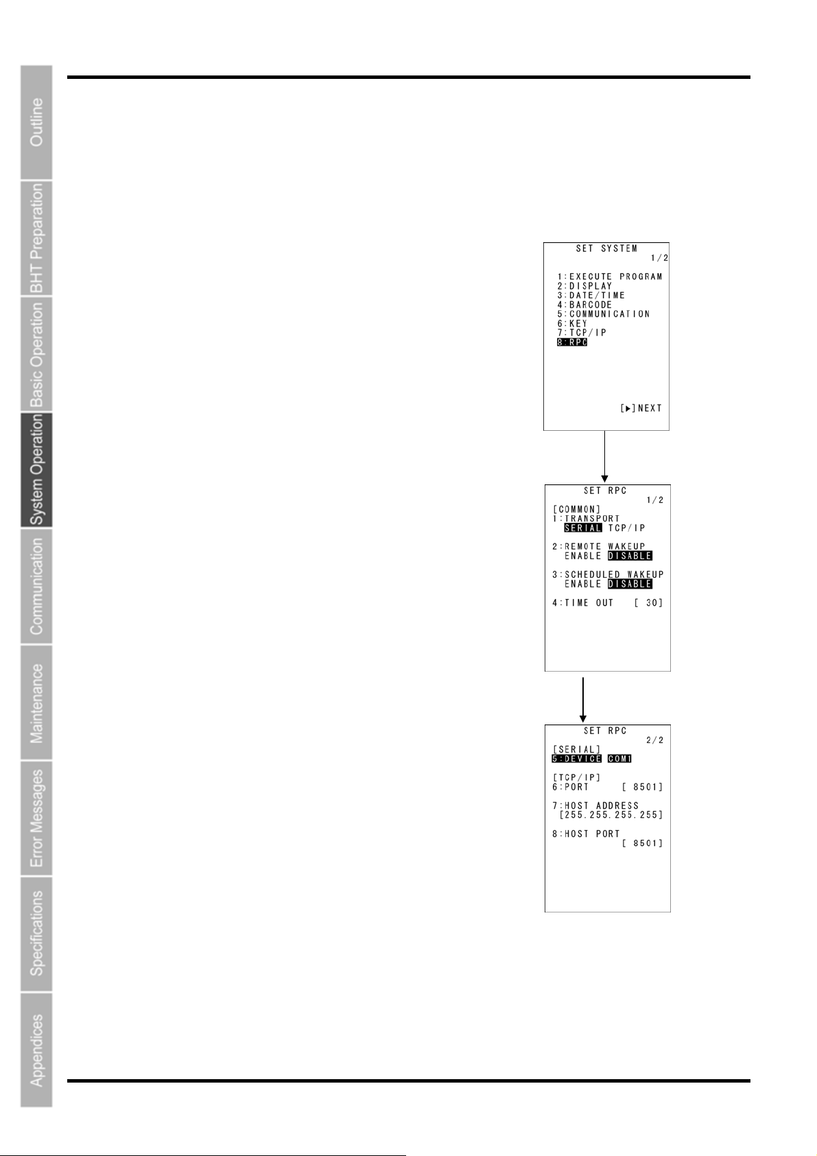
BHT-805B
[10] Setting the RPC
The BHT-800 series is compliant with the BHT Manager software (host-side tool). The RPC screen
displays the settings used to communicate with the BHT Manager software.
For details, refer to the “BHT Manager User’s Manual”. The following explains only the operation of this
menu and an outline of the settings.
1. Select “8: RPC” from the SET SYSTEM Menu 1/2 and then
press the ENT key.
The SET RPC screen on the right will display.
The highlighted setting will be the current setting.
“1: TRANSPORT”:
Selects the communication path for communicating with the BHT
Manager.
“2: REMOTE WAKEUP”:
Sets the PRC remote wakeup.
“3: SCHEDULED WAKEUP”:
Sets the scheduled wakeup.
“4: TIMEOUT”:
Sets the communication time out interval.
“5: DEVICE COM1”:
Sets the COM port when a serial communication path is used.
“6: PORT”:
Sets the port number for RPC.
“7: HOST ADDRESS”:
Sets the BHT Manager HOST-IP.
“8: HOST PORT”:
Sets the port number for the BHT Manager line connection
notification.
2. Use the cursor keys ([◄] [►]) to select each setting value.
ENT key
Select items with the [▲]
and [▼] keys.
3. Press the ENT key.
The selected value will then be set.
86
Page 100
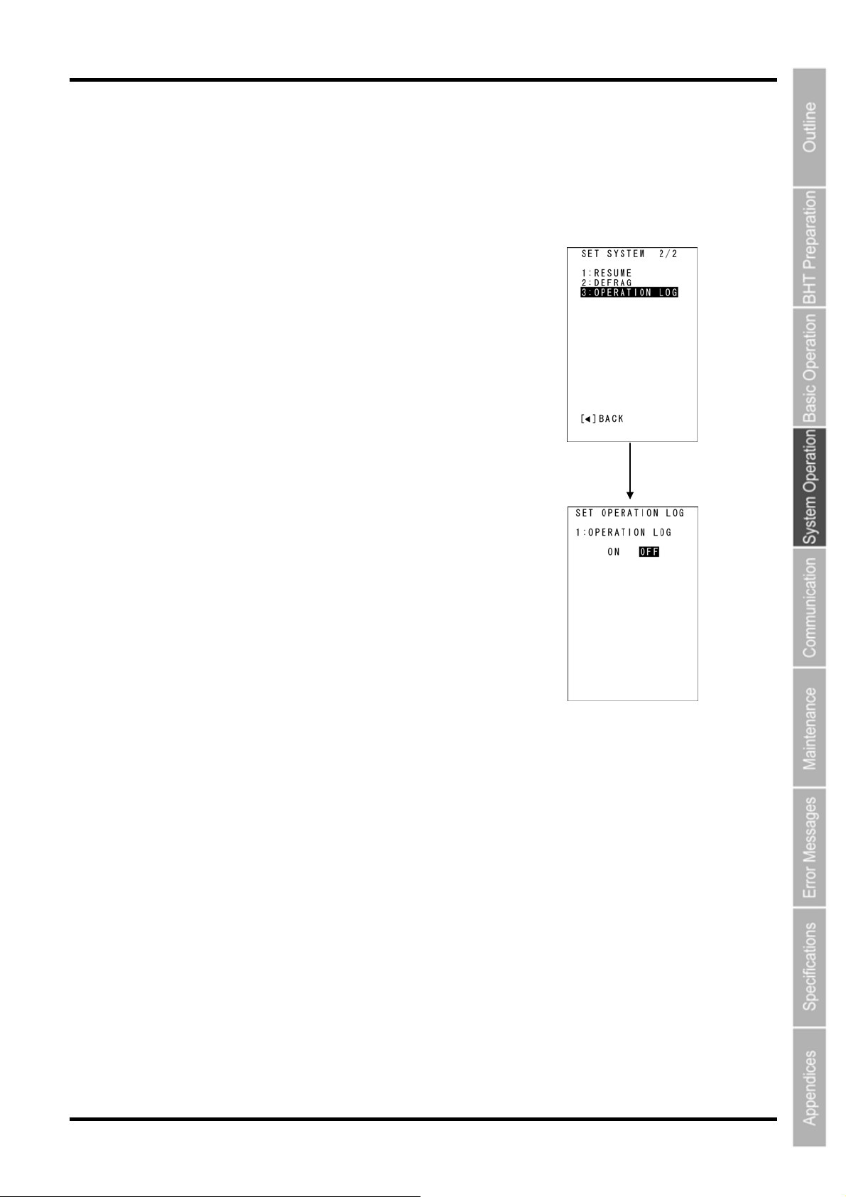
Barcode Handy Terminal
[11] Setting the operation log
The BHT-800 series is compliant with the BHT Manager software (host-side tool). The OPERATION LOG
sets wheter of not create log data that the BHT Manager collects.
For details, refer to the “BHT Manager User’s Manual”. The following explains only the operation of this
menu and an outline of the settings.
1. Select “3: OPERATION LOG” from the SET SYSTEM Menu
2/2 and then press the ENT key.
The OPERATION LOG settings menu will display.
The highlighted setting will be the current setting.
2. Use the cursor keys ([◄] [►]) to select each setting value, and
then press the ENT key.
“ON”: An operation log file is created.
“OFF”: An operation log file is not created.
3. Press the ENT key.
The selected value will then be set.
ENT key
87
 Loading...