

De Nora Capital Controls CHLORALERT T17CA4000 Series Instruction Manual
Instruction Manual
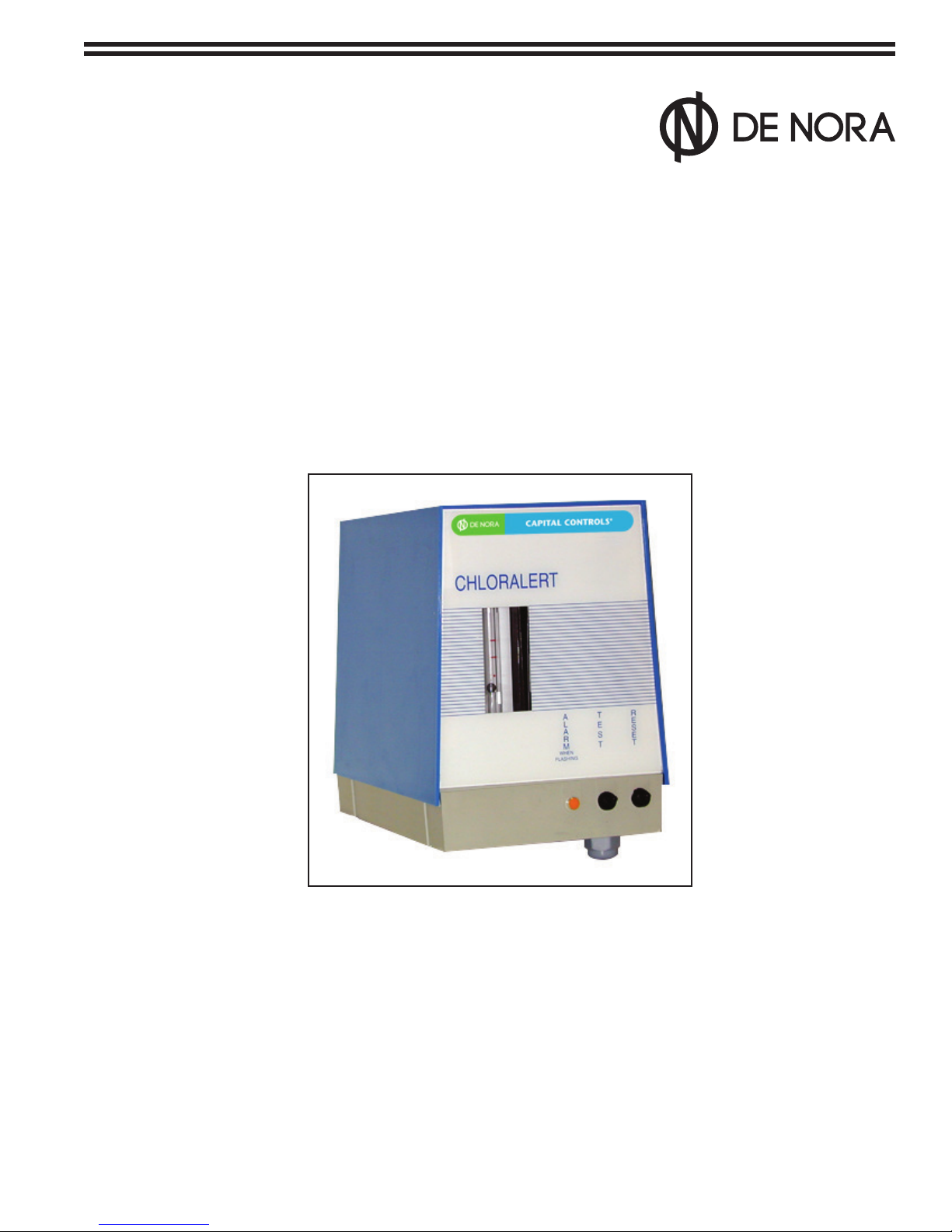
CHLORALERT
TM
Series T17CA4000
Chlorine Gas Leak Detector
CAPITAL CONTROLS
®
- 1 - 325.6030.7
These instructions describe the installation, operation and maintenance of the subject equipment. Failure to strictly
follow these instructions can lead to an equipment rupture that may cause signicant property damage, severe
personal injury and even death. If you do not understand these instructions, please call De Nora Water Technologies
for clarication before commencing any work at +1 215-997-4000 and ask for a Field Service Manager. De Nora Water
Technologies, Inc. reserves the rights to make engineering renements that may not be described herein. It is the
responsibility of the installer to contact De Nora Water Technologies, Inc. for information that cannot be answered specically
by these instructions.
Any customer request to alter or reduce the design safeguards incorporated into De Nora Water Technologies
equipment is conditioned on the customer absolving De Nora Water Technologies from any consequences of such a
decision.
De Nora Water Technologies has developed the recommended installation, operating and maintenance procedures with
careful attention to safety. In addition to instruction/operating manuals, all instructions given on labels or attached tags
should be followed. Regardless of these eorts, it is not possible to eliminate all hazards from the equipment or foresee every
possible hazard that may occur. It is the responsibility of the installer to ensure that the recommended installation instructions
are followed. It is the responsibility of the user to ensure that the recommended operating and maintenance instructions are
followed. De Nora Water Technologies, Inc. cannot be responsible deviations from the recommended instructions that may
result in a hazardous or unsafe condition.
De Nora Water Technologies, Inc. cannot be responsible for the overall system design of which our equipment may be
an integral part of or any unauthorized modications to the equipment made by any party other that De Nora Water
Technologies, Inc.
De Nora Water Technologies, Inc. takes all reasonable precautions in packaging the equipment to prevent shipping damage.
Carefully inspect each item and report damages immediately to the shipping agent involved for equipment shipped “F.O.B.
Colmar” or to De Nora Water Technologies for equipment shipped “F.O.B Jobsite”. Do not install damaged equipment.
De Nora Water Technologies, Colmar Operations
Colmar, Pennsylvania, USA
is ISO 9001: 2008 Certied
READ THE ENTIRE MANUAL BEFORE OPERATING
USE ONLY IN ACCORDANCE WITH INSTRUCTION MANUAL
WARNING: HAZARDOUS VOLTAGES
325.6030.7 - 2 -

INSTRUCTION BULLETIN
CHLORINE GAS LEAK DETECTOR
"CHLORALERT"
Model T17CA4000
Rev. 1.2
IMPORTANT
The instructions given herein cover generally the description, installation, operation and maintenance of subject
equipment.
DNWT reserves the right to make engineering renements that may not be reected in this Bulletin.
Should any question arise which may not be answered specically by these instructions, they should be directed to
De Nora Water Technologies for further detailed information and technical assistance.
DNWT takes all possible precautions in packing each equipment item to prevent damage during shipment.
Carefully inspect each item and if damage has occurred report it immediately.
Do not install any equipment if damage is such that faulty operation is likely to result.
If plant engineering drawing are available at the installation site , locate, mount , pipe and wire thesubject equipment
in accordance with these drawings.
If plant engineering drawings are not available, refer to the Installation section for information concerning these
requirements.
Carefully inspect all packing material before discarding it to prevent loss of mounting hardware, accessories, spare
parts or instructions.
All instructions given on any attached tag should be followed.
WARNING
To assure safe operation this equipment carefully follow use and installation instructions
and recommendations illustrated in this Manual. Improper use of the equipment
may damage the equipment and endanger the safety
of the operating personnel.
- 3 - 325.6030.7

PAGE INTENTIONALLY LEFT BLANK
325.6030.7 - 4 -

TABLE OF CONTENTS
1 INTRODUCTION ............................................................................................................................................................ 6
1.1 General Description ............................................................................................................................................................................. 6
2 TECHNICAL SPECIFICATIONS ....................................................................................................................................... 7
3 MODEL NUMBER BREAKDOWN ................................................................................................................................... 9
3.1 Standard accessories ............................................................................................................................................................................ 9
4 INSTALLATION .......................................................................................................................................................... 10
4.1 Location ..................................................................................................................................................................................................10
4.2 Mounting ................................................................................................................................................................................................10
4.3 Sampling line ........................................................................................................................................................................................11
4.4 Electrical wiring .................................................................................................................................................................................... 11
5 OPERATION, MAINTENANCE AND TESTING .............................................................................................................. 12
5.1 Electrolyte lling at start up ............................................................................................................................................................12
5.2 Electrolyte renewal after operation .............................................................................................................................................12
5.3 Sample ow rate ..................................................................................................................................................................................12
5.4 Gas Test 12
5.5 Circuit performance check ...............................................................................................................................................................13
6 MAINTENANCE PROCEDURES .................................................................................................................................... 14
6.1 Measuring cell maintenance ...........................................................................................................................................................14
6.2 Flowmeter ..............................................................................................................................................................................................14
6.2.1 For Model T17CA4100 ......................................................................................................................................................14
6.2.1 For Model T17CA4200 ......................................................................................................................................................14
6.3 Electronic circuit board .....................................................................................................................................................................14
6.4 Optical sensor (Only for Model T17CA4200) ..............................................................................................................................14
7 CE DECLARATION ........................................................................................................................................................ 15
FIGURES
1 CHLORALERT Internal View ................................................................................................................................................................ 4
2 Outline Dimensions .............................................................................................................................................................................. 8
3 Typical Installation ..............................................................................................................................................................................10
4 Electrical Wiring....................................................................................................................................................................................11
- 5 - 325.6030.7
 Loading...