

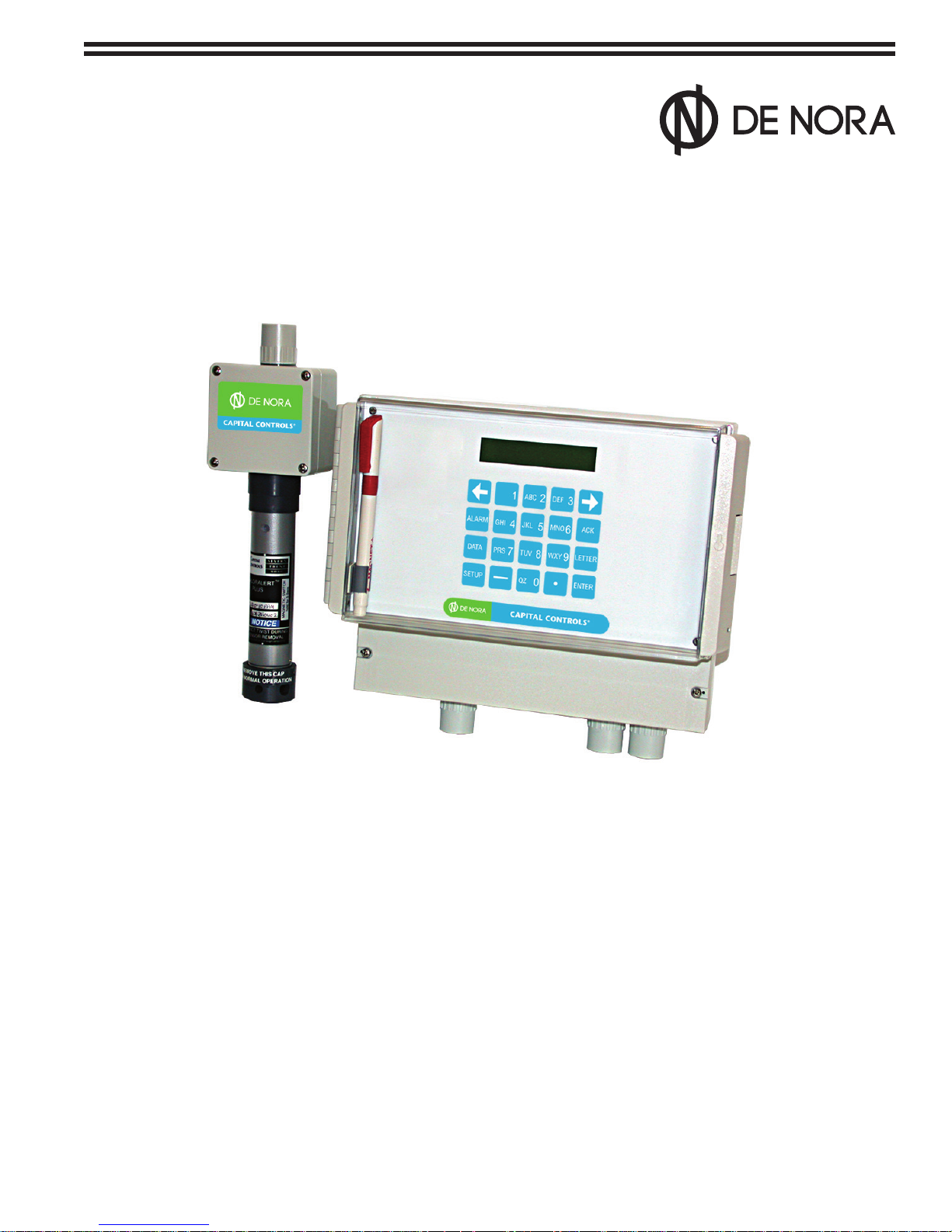
De Nora Capital Controls CHLORALERT 17CA3000 Series Instruction Manual
Instruction Manual
Series 17CA3000
Chloralert
TM
Plus Multi-Gas Detector
CAPITAL CONTROLS
®
- 1 - 325.6610.17
These instructions describe the installation, operation and maintenance of the subject equipment. Failure to
strictly follow these instructions can lead to an equipment rupture that may cause signicant property damage,
severe personal injury and even death. If you do not understand these instructions, please call De Nora Water
Technologies for clarication before commencing any work at +1 215-997-4000 and ask for a Field Service Manager.
De Nora Water Technologies, Inc. reserves the rights to make engineering renements that may not be described
herein. It is the responsibility of the installer to contact De Nora Water Technologies, Inc. for information that cannot be
answered specically by these instructions.
Any customer request to alter or reduce the design safeguards incorporated into De Nora Water Technologies
equipment is conditioned on the customer absolving De Nora Water Technologies from any consequences of such
a decision.
De Nora Water Technologies has developed the recommended installation, operating and maintenance procedures
with careful attention to safety. In addition to instruction/operating manuals, all instructions given on labels or attached
tags should be followed. Regardless of these efforts, it is not possible to eliminate all hazards from the equipment or
foresee every possible hazard that may occur. It is the responsibility of the installer to ensure that the recommended
installation instructions are followed. It is the responsibility of the user to ensure that the recommended operating and
maintenance instructions are followed. De Nora Water Technologies, Inc. cannot be responsible deviations from the
recommended instructions that may result in a hazardous or unsafe condition.
De Nora Water Technologies, Inc. cannot be responsible for the overall system design of which our equipment may be
an integral part of or any unauthorized modications to the equipment made by any party other that De Nora Water
Technologies, Inc.
De Nora Water Technologies, Inc. takes all reasonable precautions in packaging the equipment to prevent shipping
damage. Carefully inspect each item and report damages immediately to the shipping agent involved for equipment
shipped “F.O.B. Colmar” or to De Nora Water Technologies for equipment shipped “F.O.B Jobsite”. Do not install damaged equipment.
De Nora Water Technologies, Colmar Operations
Colmar, Pennsylvania, USA
is ISO 9001: 2008 Certied
READ THE ENTIRE MANUAL BEFORE OPERATING
USE ONLY IN ACCORDANCE WITH INSTRUCTION MANUAL
WARNING: HAZARDOUS VOLTAGES.
PROTECTIVE GROUND (EARTH) TERMINAL
WARNING: FAILURE TO INSTALL, SET UP OR OPERATE
THE EQUIPMENT IN THE MANNER SPECIFIED BY DE NORA WATER TECHNOLOGIES
MAY IMPAIR THE PROPER OPERATION OF THIS EQUIPMENT
325.6610.17 - 2 -

TABLE OF CONTENTS
SAFETY SUMMARY .....................................................................................................................................................7
READ FIRST .............................................................................................................................................................8
1.0 INTRODUCTION ...............................................................................................................................................9
1.1 General ....................................................................................................................................................... 9
1.2 Model Number Breakdown ....................................................................................................................... 10
1.3 Specifications ............................................................................................................................................ 11
2.0 INSTALLATION ..............................................................................................................................................13
2.1 Inspection ................................................................................................................................................. 13
2.2 Location and Mounting ............................................................................................................................. 13
2.3 Receiver Electrical Connections ............................................................................................................... 13
2.4 Sensor/Transmitter Electrical Connections ............................................................................................... 17
3.0 FUNCTIONAL DESCRIPTION .......................................................................................................................19
3.1 General ..................................................................................................................................................... 19
3.2 Features .................................................................................................................................................... 19
3.2.1 Sensors/Transmitter ..................................................................................................................... 19
3.2.1.1 Gases ........................................................................................................................... 19
3.2.1.2 Gas Concentration Range ........................................................................................... 19
3.2.1.3 Outputs ........................................................................................................................ 20
3.2.1.4 Power Consumption ..................................................................................................... 20
3.2.1.5 Sensor Cross-Sensitivity .............................................................................................. 20
3.2.2 Receiver .................................................................................................................................. 20
3.2.2.1 Input Voltage ................................................................................................................ 20
3.2.2.2 Power Requirements .................................................................................................... 20
3.2.2.3 Receiver Outputs ......................................................................................................... 21
3.2.2.3.1 Analog Outputs (AO) .......................................................................................... 21
3.2.2.3.2 Digital Outputs (DO) .......................................................................................... 21
3.2.2.4 Keypad Push-button .................................................................................................... 21
3.2.2.5 Operating Modes ......................................................................................................... 22
3.2.2.6 Password ..................................................................................................................... 22
3.2.2.7 Display Modes ............................................................................................................. 23
3.2.2.8 Watchdog Timer Circuit ............................................................................................... 24
3.2.2.9 Self-Test ....................................................................................................................... 24
3.2.2.9.1 Standard Tests ................................................................................................... 24
3.2.2.9.2 Extended Tests ................................................................................................... 24
3.2.2.9.3 Self-test Failure Messages ................................................................................. 25
3.2.2.10 Sensor Check .............................................................................................................. 26
3.2.2.11 Calibration Mode ......................................................................................................... 27
3.2.2.12 Security and Safety ...................................................................................................... 28
3.2.2.12.1 Password ............................................................................................................ 28
3.2.2.12.2 Watchdog Timer ................................................................................................. 28
3.2.2.12.3 Power Failure ...................................................................................................... 28
3.2.2.13 Battery Operation......................................................................................................... 28
3.2.2.14 Operational Alarms ...................................................................................................... 28
3.2.2.14.1 Level ................................................................................................................... 29
3.2.2.14.2 Mode .................................................................................................................. 30
3.2.2.14.3 Latch .................................................................................................................. 30
3.2.2.14.4 Delay .................................................................................................................. 31
3.2.2.15 Event Displays .......................................................................................................... 32
3.2.2.15.1 Alarm Displays ................................................................................................... 32
3.2.2.15.2 Status Event Displays ......................................................................................... 32
3.2.2.15.3 Event Queues ..................................................................................................... 33
4.0 START-UP & OPERATION .............................................................................................................................36
4.1 Firmware Level .......................................................................................................................................... 36
4.2 Calibration Data ........................................................................................................................................ 36
4.3 Quick-Start ................................................................................................................................................ 37
- 3 - 325.6610.17

4.3.1 Data Entry .................................................................................................................................... 38
4.3.2 Configuration ................................................................................................................................ 38
4.3.3 Setup ............................................................................................................................................ 39
4.3.3.1 Menu Navigation & Defaults .................................................................................................. 39
4.3.3.2 Select Sensor Channel .......................................................................................................... 41
4.3.3.3 Select Sensor Type ................................................................................................................ 41
4.3.3.4 Enter Sensor Calibration Parameters .................................................................................... 41
4.3.3.5 Configure Alarm .................................................................................................................... 42
4.3.3.6 Configure Digital Output ........................................................................................................ 43
4.3.3.7 Return to RUN MODE ............................................................................................................ 43
4.4 Menu Sequence ........................................................................................................................................ 43
4.4.1 Setup ............................................................................................................................................ 45
4.4.1.1 Direct Access ........................................................................................................................ 45
4.4.1.2 Password Protected .............................................................................................................. 45
4.4.2 Configure ..................................................................................................................................... 45
4.4.2.1 Instrument .............................................................................................................................. 45
4.4.2.1.1 Name ........................................................................................................................ 46
4.4.2.1.2 Engineering Units ..................................................................................................... 46
4.4.2.1.3 Display Mode ............................................................................................................ 47
4.4.2.1.4 Set Time .................................................................................................................... 47
4.4.2.1.5 Set Date .................................................................................................................... 47
4.4.2.1.6 Change Password .................................................................................................... 48
4.4.2.1.6.1 Override the Password ....................................................................................... 48
4.4.2.1.7 Default Database ...................................................................................................... 48
4.4.2.1.8 Set LCD Contrast ...................................................................................................... 48
4.4.2.1.9 Sensor Check ........................................................................................................... 49
4.4.2.1.10 Run Self-Test ............................................................................................................. 50
4.4.2.1.11 Enter Configuration Code ......................................................................................... 51
4.4.2.1.12 Custom Average Hours ............................................................................................ 51
4.4.2.1.13 Battery Status ........................................................................................................... 51
4.4.2.1.14 Software Version ....................................................................................................... 52
4.4.2.2 Channels ............................................................................................................................... 52
4.4.2.2.1 Tag Name ................................................................................................................. 52
4.4.2.2.2 Sensor Type .............................................................................................................. 53
4.4.2.2.3 Alarm (1,2, or 3) ........................................................................................................ 53
4.4.2.2.3.1 Level ................................................................................................................... 53
4.4.2.2.3.2 Mode .................................................................................................................. 53
4.4.2.2.3.3 Latch .................................................................................................................. 54
4.4.2.2.3.4 Delay .................................................................................................................. 54
4.4.2.2.4 Analog Output .......................................................................................................... 54
4.4.2.2.4.1 Output ................................................................................................................ 54
4.4.2.2.4.2 Span ................................................................................................................... 55
4.4.2.2.4.3 Zero .................................................................................................................... 55
4.4.2.2.4.4 Mode .................................................................................................................. 56
4.4.2.2.4.5 Calibration (Analog Output Parameters) ............................................................ 56
4.4.2.2.5 Calibration (Sensor Parameters) .............................................................................. 57
4.4.2.2.5.1 Concentration ..................................................................................................... 57
4.4.2.2.5.2 Span ................................................................................................................... 57
4.4.2.2.5.3 Zero .................................................................................................................... 57
4.4.2.2.5.4 Sensor Data........................................................................................................ 58
4.4.2.3 Digital Outputs ....................................................................................................................... 58
4.4.2.3.1 Source ...................................................................................................................... 58
4.4.2.3.2 Invert ......................................................................................................................... 59
4.4.2.3.3 State .......................................................................................................................... 59
4.4.2.4 Comm Por t ........................................................................................................................... 59
4.4.2.4.1 Baud Rate ................................................................................................................. 60
4.4.2.4.2 Instrument Address .................................................................................................. 60
4.4.2.4.3 Parity ......................................................................................................................... 60
325.6610.17 - 4 -

4.4.2.4.4 Datalink Enable .......................................................................................................... 61
4.4.2.4.5 Datalink Protocol ........................................................................................................61
4.4.3 Run Calibration ....................................................................................................................... 61
4.4.4 Stop Calibration ...................................................................................................................... 62
5.0 CALIBRATION ........................................................................................................................... 63
5.1 Sensor Calibration ............................................................................................................................63
5.1.1 Setup ............................................................................................................................ 63
5.1.2 Source ............................................................................................................................63
5.1.3 Calibration ............................................................................................................................63
5.1.3.1 General Calibration Overview .......................................................................................... 63
5.1.3.2 ZERO Calibration Procedure ............................................................................................ 65
5.1.3.3 SPAN Calibration Procedure ............................................................................................66
5.2 Analog Output Calibration ......................................................................................................................... 66
5.2.1 Minimum Output Current Calibration ...................................................................................... 67
5.2.2 Maximum Output Current Calibration ..................................................................................... 67
6.0 COMMUNICATIONS ........................................................................................................................... 68
6.1 General 68
6.2 Interconnections 68
6.2.1 RS232 Plug Connections ........................................................................................................69
6.2.2 RS422/485 Plug Connections .................................................................................................69
6.3 Configuring the System Module for Datalink .............................................................................................70
6.4 Protocol 70
6.4.1 Message Types ...................................................................................................................... 71
6.4.1.1 Host to Instrument ............................................................................................................ 71
6.4.1.2 Instrument to Host ............................................................................................................ 72
6.4.2 Transaction Examples.............................................................................................................72
6.5 Mnemonic-to-Datapoint Cross Reference .................................................................................................72
6.5.1 Database Starting Addresses ................................................................................................ 73
6.5.2 Instrument Memory Address Scheme ....................................................................................73
6.6 Executing Instrument Self Tests Using Datalink ........................................................................................74
6.7 Database Prompt-to-Datapoint Cross Reference ......................................................................................75
7.0 MAINTENANCE ........................................................................................................................... 81
7.1 General ............................................................................................................................81
7.2 Routine Maintenance ............................................................................................................................81
7.3 Sensor/Transmitter Replacement ............................................................................................................... 81
7.4 Troubleshooting 82
7.4.1 General Troubleshooting ........................................................................................................82
7.4.2 Sensor Troubleshooting .......................................................................................................... 83
LIST OF FIGURES
Figure 1-1 Basic System Configuration ......................................................................................................................... 9
Figure 1-2 Receiver Data Tag ...................................................................................................................................... 10
Figure 2-1 Receiver Outline Dimensions ..................................................................................................................... 14
Figure 2-2 Sensor/Transmitter Outline Dimensions ..................................................................................................... 15
Figure 2-3 Interconnection Diagram ........................................................................................................................... 16
Figure 2-4 Sensor Wiring ............................................................................................................................................. 18
Figure 3-1 Chloralert Plus Keypad .............................................................................................................................. 22
Figure 3-2 Basic Alarm Operation ............................................................................................................................... 29
Figure 3-3 Self-Resetting Alarm Operation ................................................................................................................. 31
Figure 3-4 Latching Alarm Operation .......................................................................................................................... 31
Figure 4-1 Receiver Data Tag ...................................................................................................................................... 36
Figure 4-2 Sensor Calibration Tag ............................................................................................................................... 36
Figure 4-3 Startup Phases .......................................................................................................................................... 37
Figure 4-4 Receiver Data-Entry Keypad ...................................................................................................................... 38
Figure 5-1 Label & Magnet Orientation ....................................................................................................................... 64
Figure 6-1 RS-232 or RS-485 Datalink Module ........................................................................................................... 68
Figure 6-2 RS-232 Plug Connector ............................................................................................................................. 69
Figure 6-3 RS-485 Plug Connector ............................................................................................................................. 69
Figure 6-4 Floating Point Examples ............................................................................................................................. 73
- 5 - 325.6610.17

LIST OF TABLES
Table 2-1 Sensor Wiring and Configuration ......................................................................................................... 17
Table 3-1 Gas Cross-Sensitivity Data .................................................................................................................. 20
Table 4-1 Factory Default Database Parameters ................................................................................................ 40
Table 6-1 System Prompts (Datalink) .................................................................................................................. 70
Table 6-2 Datalink Protocol ................................................................................................................................. 71
Table 6-3 Datapoint Types ................................................................................................................................... 73
Table 6-4 Database Starting Addresses ............................................................................................................. 74
Table 6-5 Datapoint Addresses ........................................................................................................................... 72
Table 6-6 Prompt-to-Datapoint Cross Reference ........................................................................................... 75-80
325.6610.17 - 6 -

SAFETY SUMMARY
GENERAL RETURN OF EQUIPMENT
WARNINGS All equipment being returned to De Nora Water Technologies for repair must be free
of any hazardous materials. Contact De Nora Water Technologies for authorization prior
to returning equipment.
INSTRUCTION MANUALS
Do not install, maintain or operate this equipment without reading, understanding
and following the proper De Nora Water Technologies instructions and manuals,
other wise injury or damage may result.
ELECTRICAL SHOCK HAZARD
Equipment powered by AC line voltage presents a potential electric shock hazard
to the user. Make certain that the system power is disconnected from the operating
branch circuit before attempting electrical interconnections of service.
SPECIFIC WARNINGS ELECTRICAL SHOCK HAZARD
Equipment powered by AC line voltage presents a potential electric shock hazard.
Servicing of the Chloralert Plus should only be attempted by a qualified electronics
technician.
WARNING: ELECTRIC SHOCK HAZARD
Equipment powered by AC line voltage presents a potential electric shock hazard to
the user. Make certain that the system power input and Digital Output replay
connections are disconnected from the operating branch circuit before attempting
to connect Sensors to the Receiver. (pg.17 )
All alarm operation is temporarily totally disabled during this test. (pg.51)
There is no automatic link between this menu entry and the units selected in the
Engineering Units menu (refer to section 4.4.2.1.2) or the range selected in the
Sensor Type menu. The operator must be careful to select a level value entry that
is within the instrument’s operating range, otherwise the alarms will not operate.
(pg.53)
- 7 - 325.6610.17

SPECIFIC After making Sensor/Transmitter electrical connections, care must be taken to replace the
CAUTIONS Sensor/Transmitter wiring box cover properly. The wiring box is not perfectly square (refer to
Figure 2-2) and the cover must be aligned properly to the box in order for the gasket to seal
the box properly. (pg.17)
In SETUP, ALARM, and DATA modes, gas monitoring continues to take place even though
concentration values are not shown on the display. However, when in SETUP, selection of
CALIBRATE, SELF-TEST, or SENSOR-CHECK functions will temporarily suspend normal gas
monitoring. (pg.24)
When power is restored after a power failure, displayed averages will be reset and valid data
will not be available until 15 minutes or 8 hours have been accumulated for the STEL and TWA
modes respectively. (pg.30)
Averaging data will be accumulated from the time the RUN CALIBRATION key is pressed until
the calibration process is actually begun by activating the Sensor’s magnetic switch. Once
Calibration has been activated, data accumulation is sus pended until Calibration is completed.
Data accumulation is suspended during SENSOR CHECK, CALIBRATION (begins when the
sensors magnetic switch is activated) and SELF-TEST. (pg.30)
If the measured gas concentration exceeds the maximum range, the data will be accumulated
at the maximum range rate. The average data after the over-range event will be in error for
the next averaging period. The over-range event is displayed and may also be retrieved from
the data archive. If the instrument is set up such that alarm level 3 is at the ma ximum r ange,
remote notification of this type of occurrence is possible. (pg.30)
The value of the gas concentration entered must be within the range selected from the SENSOR
TYPE menu (refer to section 4.4.2.2.2), otherwise an erroneous operation will result. (pg.55)
If cleaning of the sensor housing is performed, do not clean the Sensor/Transmitting housing
with cleaners containing strong mineral acids or organic solvents such as ketones, chlorinated
hydrocarbons, or aromatics. Using such cleaners may damage the housing materials. Cleaning
of the sensor housing materials should only be performed using soap and water. (pg.81)
Sensor removal must be done by pulling the sensor from the circuit board without rotating or
twisting the sensor. Rotation will cause serious damage to the sensor pins. (pg.82)
READ FIRST
WARNING
INSTRUCTION MANUALS
Do not install, maintain, or operate this equipment without reading, understanding and
following the proper De Nora Water Technologies instructions and manuals, otherwise
injury or damage may result.
RETURN OF EQUIPMENT
All equipment being returned to De Nora Water Technologies for repair must be
free of any hazardous materials. Contact De Nora Water Technologies for authorization
prior to returning equipment.
This instruction bulletin contains general operating information about the Chloralert™ Plus Multi-Gas Detector as well
as instructions for installation and troubleshooting.
Read these instructions before starting installation.
Save these instructions for future reference.
325.6610.17 - 8 -
1.0 INTRODUCTION
1.1 General
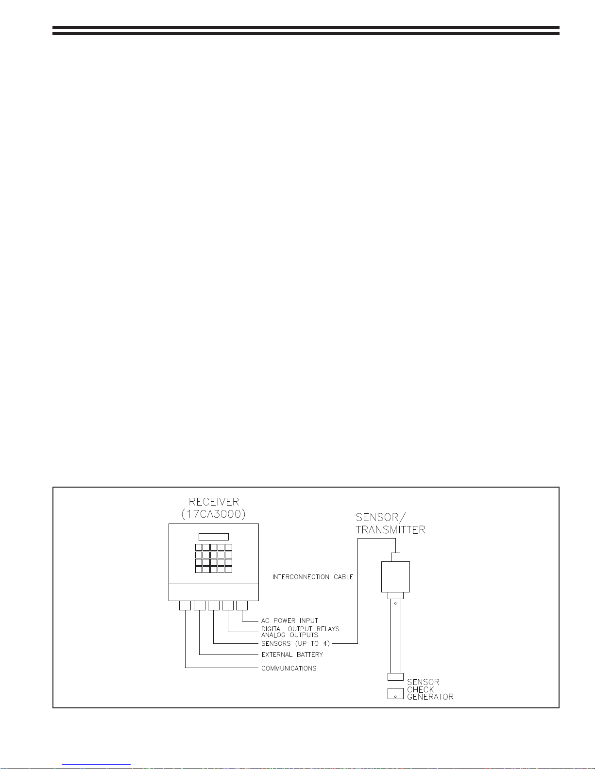
The Chloralert™ Plus multifunction gas-leak detector is designed to be used for the detection and monitoring of
Chlorine (Cl
concentration of these gases exceeds programmable preset levels. The basic system consists of the Receiver
and one to four Sensor/Transmitters and has provision for additional optional features (refer to Figure 1-1). In use,
the sensor assemblies are mounted near the potential sources of leaks or emissions. The receiver assembly may
be located up to 1000 ft from the sensor. It converts the signal from the sensor/transmitter to the digital display of
gas concentration, activates alarm(s) or other safety devices, transmits 4-20 mA signals for recording or control
purposes, and permits serial communication via RS485 or RS232 protocols.
The receiver is available as a wall mounted, NEMA 4X enclosure 10.9W x 8.6H x 5.3 inches deep containing a main
circuit board, keyboard, and display. The electronics consist of a power supply and signal-processing circuitry
for up to four sensor inputs, battery charging circuit for an optional external battery back-up, a malfunction relay
and two alarm relays. Support for three separate optional electronics packages is included on the main board:
Communications (RS232 or RS485), 4 channels of 4-20 mA analog outputs, and six additional digital output relays
(SPST). All relays are rated at 1.5/240VAC.
The receiver is supplied with three conduit connectors for sensor, replay, and ac power connections. An additional
four conduit connectors for optional accessories are supplied in a separate bag.
) and Sulfur Dioxide (SO2) in ambient air. It also activates audio and visual alarms in the event that the
2
The sensor includes dedicated transmitter electronics because of individual sensor setup requirements and is
currently available in four types (Cl
assembly containing sensor and solid state electronics. The sensors are powered from the receiver which will
power 4 sensors for a minimum of 24 hours during a power outage when supplied with the optional back-up bat-
tery. Appropriate cable lengths may be ordered separately.
A sensor-check (auto-generator) feature is available for each sensor type. It consists of a small gas generator
which is assembled on the end of the sensor and is wired in the junction box assembly. This allows testing of the
sensor’s integrity and verifies that the sensor is functioning properly.
& SO2). A waterproof package (NEMA 4X) consists of a factory-calibrated
2
- 9 - 325.6610.17
Figure 1-1 Basic System Configuration

1.2 Model Number Breakdown
The following table shows the individual fields of the instrument’s model number and the selections
available for each. Refer to the receiver’s data tag (shown below) for the specific model number
configuration of the instrument.
17CA3
Enclosure
Standard Wall Mounting 1
Standard With key Locked door 2
Analog Outputs
None 0
4 ANO 1
Digital Outputs
3 DO 0
9 DO 1
Design Level A
Communications
None 0
RS485 1
RS232 2
Sensor Channel - Calibrated with Detector*
Not Required 0 0 0 0
Chlorine Sensor - (0-5 PPM) 1 1 1 1
Chlorine Sensor - (0-10 PPM) 2 2 2 2
Chlorine Sensor - (0-50 PPM) 3 3 3 3
Chlorine Sensor with Sensor Check - (0-5 PPM) 4 4 4 4
Chlorine Sensor with Sensor Check - (0-10 PPM) 5 5 5 5
Chlorine Sensor with Sensor Check - (0-50 PPM) 6 6 6 6
Sulfur Dioxide Sensor - (0-10 PPM) 7 7 7 7
Sulfur Dioxide Sensor - (0-20 PPM) 8 8 8 8
Sulfur Dioxide Sensor - (0-100 PPM) 9 9 9 9
* Specify type and quantity of sensor(s) required (4 maximum)
325.6610.17 - 10 -

1.3 Specifications
SYSTEM:
Gases Chlorine
Sulfur Dioxide
Channels/Gases 4 max., channels and gas interchangeable
for each receiver
Gas Conc. Ranges Chlorine: 0-5, 0-10, 0-50 ppm
Sulfur Dioxide: 0-10, 0-20, 0-100 ppm
Ambient Temperature Receiver: -5 to +55°C (23 to 131°F)
Sensor: -30 to +55°C (-22 to 131°F)
Ambient Pressure: 0.8 to 1.2 atmospheres
AC POWER:
Voltage Range 93.5 to 276 Vac
Frequency Range 47-63 Hz
Power Consumption Receiver- 10 watts nominal, 12 watts max.
Electrochemical Sensor/Transmitter- 0.5 watts max.
Voltage Dropout Duration < 20 ms
Permitted
RECEIVER:
Signal Digital Communication
RS 232/485 (optional),
4-20 mA each channel (optional)
Relays 3 SPDT Standard, Additional 6 SPST optional
Relay contacts rated at 3.15 Amps/240 Vac
Optional relays are field replaceable
Annunciators Flashing display indication for concentration alarms and other
significant events. Display backlight turned off during battery
operation or if battery is faulty.
Alarm Levels Selectable, 3 programmable concentration alarm levels
for each channel.
Alarm Modes Selectable, TWA, Instantaneous, STEL, and Customer Defined
Alarm Operation Selectable, normal (self-resetting), latched and delayed.
Display Back-lit LCD, 2 lines x 20 characters
Keyboard Polyester, 20 tactile key position
Diagnostics System, power and sensor failure
Security Password-protected
- 11 - 325.6610.17

Max. Distance Receiver to
Sensor/Transmitter: 1000 ft.
Wires (Xmttr/Receiver) 2
Sample Draw None
Sensor Check Optional
Housing
Sensor/Transmitter:
Dimensions: 3.2 in.(W) x 11.0 in.(H)* x 2.2 in.(D)
*12.6 in.(H) with gas-generator
Weight: 1 lb.
Materials: Electronic Housing Tube-PVC
Junction Box-polycarbonate
Receiver:
Dimensions: 10.9 in.(W) x 8.6 in.(H) x 5.3 in.(D)
Weight: 5 lb.
Materials: Enclosure-polystyrene
Clear Front-polycarbonate
Battery:
Dimensions: 10.5 in.(W) x 9.0 in.(H) x 6.5 in.(D)
Weight: 15 lb.
Mounting: Wall
ENCLOSURES: NEMA 4X(IP65)
OPTIONS:
4 ANO Option Contains circuitry for transmitting four 0-20 mA or 4-20 mA analog
current outputs propor tional to gas concentration levels. The analog
outputs are not isolated since they all share the same “circuit
common” return point (Refer to Figure 2-4).
6 DO Option Contains six additional SPST relay circuits, thus allowing for two
relays for each gas channel.
Communications Plug-in models for RS232 or RS485
ACCESSORIES:
External Battery Includes battery (w/storage case) allowing a minimum of 24 hours
of operation
Sensor Cable Available in any length (in feet) up to 1000 ft. max.
Sensor-Check Generators Attach to end of sensor. Discharge gas into the sensor to verify
sensor and receiver operation. Controlled by the Receiver.
SENSOR:
Sensor Type Electrochemical (EC)
Minimum Detectable Chlorine: 0.1 ppm
Concentration Sulfur Dioxide: 0.1 ppm
Calibration Mode automatic, remote single person, non-intrusive
325.6610.17 - 12 -

2.0 INSTALLATION
2.1 Inspection
The equipment should be inspected for damage that may have occurred during shipment. All damage should
be reported to the shipping agent. If the equipment is damaged to the extent that faulty operation may result,
contact De Nora Water Technologies before installation. Always reference the complete instrument serial
number and model number in all correspondence concerning the equipment supplied.
2.2 Location and Mounting
The Model 17CA3000 Chloralert™ Plus Receiver may be wall-mounted close to the gas sensor(s) or may be
located up to 1000 feet from the sensor(s). Refer to Figure 2-3 for the recommended interconnection diagram.
Mounting-ears are supplied with the Receiver and the Sensor/Transmitter and may be used for convenient
wall-mounting (Refer to Figures 2-1 and 2-2 respectively). The mounting ears may be oriented in several
directions to facilitate convenient mounting. It is recommended that both receiver and sensor/transmitter
be oriented vertically as shown in Figure 1-1. Mounting screws or any other mounting hardware desired or
required is supplied by the customer.
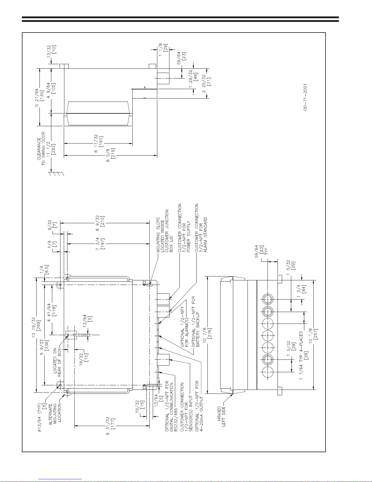
The receiver case is supplied, configured with three ½-NPT conduit fittings for customer wiring (Refer to
Figure 2-1). The receiver enclosure contains four additional knockouts for attachment of additional conduit
fittings. These provide a means of wiring optional features like digital communications, analog outputs, battery
backup and alarms.
Select a location which gives limited access to unauthorized personnel and where ambient temperature remains
within the temperature range specified in section 1.3. The installation area should be well
ventilated and provided with a source of heat, if necessary, to ensure that the ambient temperature does not
fall below the specified minimum temperature.
The selected location must be of sufficient size to provide necessary equipment clearances and to allow easy
access for routine inspection and maintenance of the Chloralert Plus Receiver and its gas sensor/transmitters.
Refer to Figures 2-1 and 2-2 for outline dimensions of the Chloraler t™ Plus Receiver and Sensor/Transmitter
Assembly respectively.
Locate the sensor module 12" to 36" (305 to 915 mm) from the floor with the sensor pointed downward.
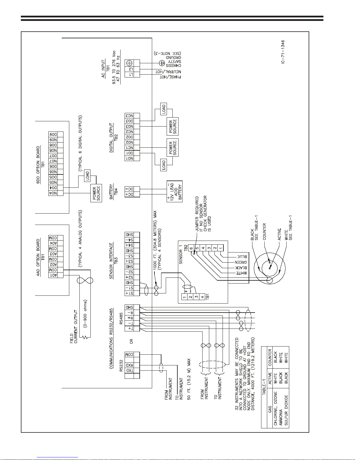
2.3 Receiver Electrical Connections
Electrical wiring including AC power, sensor and alarm relay interconnections should be performed in
accordance with the interconnection diagram shown in Figure 2-3. Refer to section 2.4 for detailed sensor/
transmitter assembly wiring.
WARNING
ELECTRICAL SHOCK HAZARD. Equipment powered by AC line voltage
presents a potential electric shock hazard to the user. Servicing of the
Chloralert Plus should only be attempted by a qualified electronics technician.
- 13 - 325.6610.17
325.6610.17 - 14 -
Figure 2-1 Receiver Outline Dimensions
- 15 - 325.6610.17
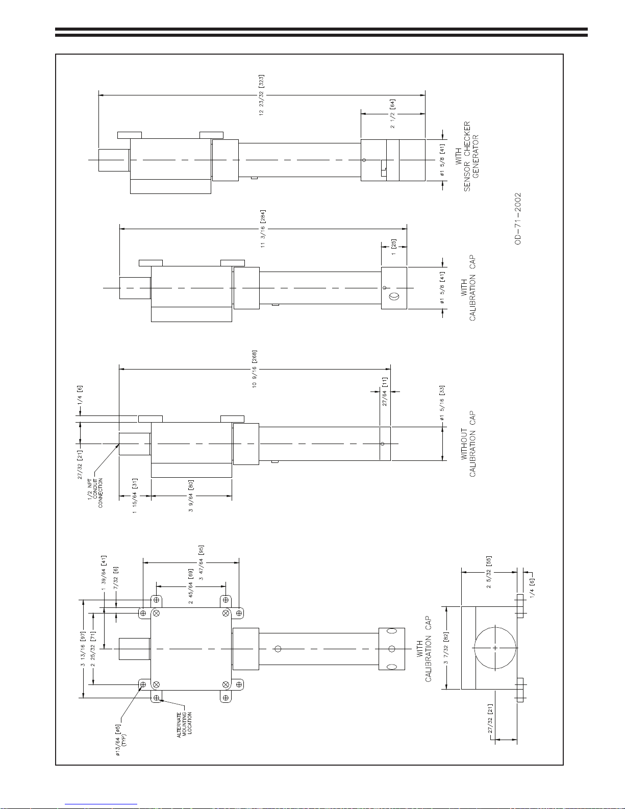
Figure 2-2 Sensor/Transmitter Outline Dimensions
325.6610.17 - 16 -
Figure 2-3 Interconnection Diagram
2.4 Sensor/Transmitter Electrical Connections
Number of Sensors Sensor Terminals
Channel
1 1 S1+, S1 1
2 1
2
S1+, S1S2+, S2-
1
2
3 1
2
3
S1+, S1S2+, S2S3+, S3-
1
2
3
4 1
2
3
4
S1+, S1S2+, S2S3+, S3S4+, S4-
1
2
3
4
WARNING
ELECTRICAL SHOCK HAZARD. Equipment powered by AC line
voltage presents a potential electrical shock hazard to the user.
Make certain that the system input and digital output relay connections
are disconnected from the operating branch circuit branch circuit before
attempting to connect sensors to the receiver.
Precautions must be taken to insure that the sensor/transmitter assembly is correctly wired to the receiver. The
sensor/transmitter assembly interfaces with the receiver circuitry via the sensor interface, terminal block TB3.
This terminal block consists of 12-positions organized into 3 terminals for each of the four possible sensors.
Each sensor is wired to a S+, S- and SHD (shield) terminal.
WARNING
Calibrated Sensors are calibrated to a specific channel on the
gas detector and are required to be wired as such
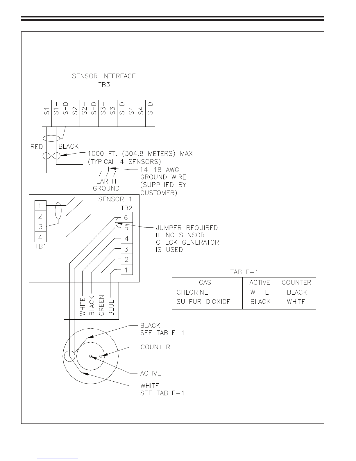
Sensor wiring for the Chlorine Electrochemical Sensor is shown in Figure 2-4. The example shown in the figure
shows a single sensor wired to terminals S1+ and S1- on TB3. These terminals correspond to CHANNEL 1 in the
SETUP-CONFIGURATION-CHANNELS menu selection discussed in chapter 4.0, START-UP AND OPERATION.
For a single-sensor system, it is recommended that the sensor be connected to the S1+ and S1- terminals and
that it be configured as CHANNEL 1 in the firmware. The sensor wires are polarized and the RED wire must
be connected to the “+” terminal while the BLACK wire connects to the “-“ terminal. As mentioned previously,
the figure shows wiring for a single-sensor system. If additional sensors are being used, the suggested wiring
configuration is shown in Table 2-1 below.
Although the above table shows recommended wiring, a sensor may be wired to any CHANNEL as long as
the configured CHANNEL corresponds to the terminals to which the sensor is wired. For example, a single
sensor may be wired to the S3+ AND S3- terminals as long as the CHANNEL 3 is configured for that sensor
in the configuration menu. Wiring a sensor to S2+ and S2- terminals and configuring CHANNEL 1 will cause
a sensor alarm to be generated.
After making sensor/transmitter electrical connections, care must be
- 17 - 325.6610.17
taken to replace the sensor/transmitter wiring box cover properly. The wiring
box is not perfectly square (refer to Figure 2-2) and the cover must be aligned
properly to the box for the gasket to seal the box properly.
Table 2-1 Sensor Wiring and Configuration
CAUTION
325.6610.17 - 18 -
Figure 2-4 Sensor Wiring

3.0 FUNCTIONAL DESCRIPTION
3.1 General
The 17CA3000 Chloralert Plus normally consists of two distinct elements, the sensor/transmitter and the receiver.
The sensor/transmitter is located near potential sources of gas leaks or emissions while the receiver is located
remotely in a control room, although in some instances, they may both be located at the same site.
Both elements of the device have inputs and outputs. The sensor/transmitter is powered by the receiver to
operate the electronics as well as the sensor, it transmits a multiplexed frequency-modulated (FM) signal to
the receiver. This conditioned sensor signal is a function of the gas concentration being monitored by the
sensor. The receiver accepts the sensor/transmitter input, converts it to a display of the gas concentration,
activates alarms and other safety devices, and transmits an analog output current signal (if so configured) for
recording or control purposes. Additionally, setup and configuration data are available via an optional remote
serial data communications port. The receiver may also receive information such as that needed for a set up
and calibration from an external computer via this datalink (Refer to section 6.0).
The receiver is also used to set up the database for the various alarm functions and the required calibration
information. Several alarm modes are available; Instantaneous, STEL, TWA, or Custom. It also provides
information during the calibration procedure about the status of the calibration as it proceeds.
The main board in the receiver contains the power supply for all sensor/transmitters, the microprocessor, three
(standard) programmable alarm relays and associated electronics. Four optional features are available:
• Four 0-20 mA or 4-20 mA ANALOG OUTPUTS for transmission of the gas
concentration levels.
• Six additional DIGITAL OUTPUT relays
• RS232 or RS485 Communications Port
• Battery Backup
The purpose of this chapter is to give an overview of some of the features of the 17CA3000. For actual
operational and data-entry procedure, refer to section 4.0.
3.2 Features
3.2.1 Sensor/Transmitter
3.2.1.1 Gases
Presently, the system is designed to monitor two gases:
• Chlorine
• Sulfur Dioxide
3.2.1.2 Gas Concentration Range
The Chloralert™ Plus uses frequency to transmit the sensor/transmitter information to the
receiver. The accuracy for any given concentration is then determined by the concentration
used for calibration.
- 19 - 325.6610.17

3.2.1.3 Outputs
The output of the sensor/transmitter is wired directly to a terminal block in the receiver so care
should be taken that the sensor is correctly connected to the receiver (refer to section 2.4). If
the sensor/transmitter is connected incorrectly, no damage will occur but the LED indicator on
the sensor/transmitter will not light and the LCD display on the receiver will indicate “BAD ID”.
The output of the sensor/transmitter consists of two multiplexed frequencies which provide
information for ambient temperature and sensed gas concentration. Refer to section 7.4.2 for
additional information.
3.2.1.4 Power Consumption
Nominal power requirement for the sensor/transmitter is approximately 0.5 watts per
individual sensor.
3.2.1.5 Sensor Cross-Sensitivity
The sensor may also be responsive to gases in sampled air other than the target gas. The
degree of the sensitivity may cause an error in the concentration reading of the target gas.
Table 3-1 below shows the typical concentration errors to be expected when a chlorine sensor
is exposed to the indicated concentrations of “interference” gases.
Table 3-1 Gas Cross-Sensitivity Data
Gas Concentration
(ppm)
CF Equivalent
(ppm)
Carbon Monoxide 300 0
Hydrogen Sulphide 15 approx. -0.5
Sulphur Dioxide 5 0
Nitric Dioxide 35 0
Nitrogen Dioxide 5 approx. 5
Hydrogen 100 0
Hydrogen Cyanide 10 0
Hydrogen Chloride 5 0
Ethylene 100 0
Sensor response to an instantaneous change of 50% relative humidity would be a chlorine
equivalent of approximately +/-0.5 ppm lasting for 2 minutes with no permanent effect. Longerterm changes in relative humidity (>5 minutes) have no effect.
3.2.2 Receiver
3.2.2.1 Input Voltage
The receiver is designed to operate on any voltage between 93.5 and 276 Vac without the
need for the customer to make adjustments should he decide to change voltage sources.
The sensor/transmitter is powered by the receiver.
3.2.2.2 Power Requirements
Overall system power requirements range from 10 to 14 watts and varies depending on which
system features are activated. Optional backup power is available to provide power during
AC power losses. Battery life is at least 24 hours with all sensors and options active. Battery
charge is automatically maintained by the receiver and no operator intervention is required.
325.6610.17 - 20 -

3.2.2.3 Receiver Outputs
The outputs of the receiver fall into two categories
• Analog - gas concentration data as a linear current output
• Digital - relay contact-closure
3.2.2.3.1 Analog Outputs (AO)
An optional 4-20 mA or 0-20 mA analog output linearly proportional to sensed gas
concentration is available on terminal block TB1 for each sensor channel. The
analog output specifications are given below:
Feature Specification
Max. Number 4
Rated Signal Range 0-20 mA or 4-20 mA
Control Range 0-21.5 mA
No-Load Voltage to 24 V
Load Range 900 ohms
Filter Time Constant 50 ms
Output Measurement Error < +/- 0.02 mA
Temperature Coefficient < +/-0.02 mA/°C
The analog outputs are not isolated since they all share the same “circuit common”
return point (Refer to Figure 2-4).
3.2.2.3.2 Digital Outputs (DO)
Three SPDT relay outputs are standard on the Chloralert Plus main circuit board.
Access to normally open (NO) and normally closed (NC) contacts is provided via
terminal block TB2.
A circuit board with an additional six output relays with SPST normally open (NO)
contact arrangement is available as an option to provide additional alarm functionally,
if desired. Contact outputs are available on TB1.
The inputs that control the digital output (DO) relays are selected by the operator using
the receiver’s SETUP-CONFIGURATION-DIGITAL OUTPUTS mode (Refer to section
4.4.2.3). The Chloralert™ Plus is able to be configured by the customer to allow control
of all DO’s by a single input or to allow each DO to be controlled by a different input.
The operator should maintain a listing of the functions assigned to each digital output.
The need for separate relays for each channel depends on the device connected to the
relay and the location of the various sensor/transmitters. If each of these is mounted
remotely in different locations then each channel requires dedicated relays to alert
attending personnel of a gas release.
The normal/delayed option allows the operator to cope with output surges that are due
to electrical pickup rather than a genuine gas exposure. This mode is only important
whenever the alarm is set to instantaneous concentration, not TWA or STEL. This alarm
delay may be used to eliminate alarms during power-up (refer to section 4.3), thereby
eliminating false alarms.
3.2.2.4 Keypad Push-button
The keypad contains a total of 20 push-button arranged in a 4-row x 5-column
matrix. The keypad layout is shown in Figure 3-1.
- 21 - 325.6610.17
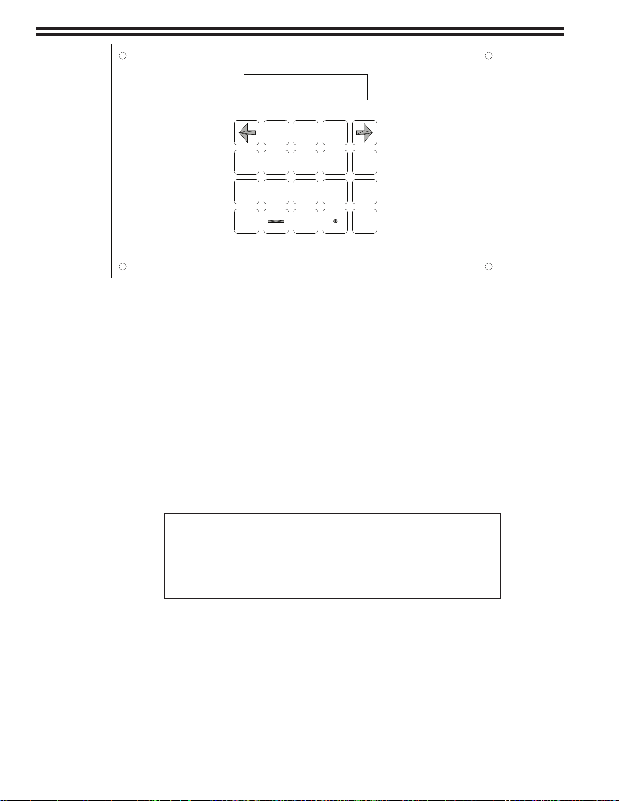
Figure 3-1 Chloralert™ Plus Keypad
DEF
1 32
ABC
6
MNOJKL
5
GHI
4
WXY
9
TUV
87
PRS
QZ
0
SETUP
DATA
ALARM
ENTER
LETTER
ACK
3.2.2.5 Operating Modes
The following four modes of operation may be selected:
• RUN - displays concentration data
• SETUP - setup menu
• ALARMS - active alarm/events queue
• DATA - historical alarm/events queue
When the power is first applied, the unit activates in the RUN mode. In this mode, the
display shows active gas concentration information. SETUP, ALARM, and DATA modes
can be selected by pressing the appropriate key on the front panel keypad. These keys
are used to “toggle” between the respective modes and RUN. Since the RUN mode has
no key associated with it, PRESSING THE RESPECTIVE MODE KEY AGAIN RETURNS
THE UNIT TO THE RUN MODE. For example, in order to return to RUN mode from any of
these operating modes, the user must press the current mode key again (i.e., if in SETUP
mode and the SETUP key is pressed, the operating mode returns to the RUN mode).
CAUTION
In SETUP, ALARMS, and DATA modes, gas-monitoring
continues to take place even though concentration values are
not shown on the display. However, when in SETUP, initiation
of CALIBRATION, SELF-TEST, or SENSOR CHECK functions
will temporarily suspend normal gas-monitoring.
3.2.2.6 Password
When the receiver initializes to the default parameters, password-protection is disabled
and the operator must automatically enter the SETUP menu by pressing the SETUP k e y.
Password-protection may be enabled, if desired, by entering the SETUP mode and
selecting the CONFIGURE-INSTRUMENT-CHANGE PASSWORD menu item (Refer to
section 4.4). The user may then enter a numerical or alphanumerical password.
If password-protection is enabled, the user will be required to enter his password whenever
attempting to enter the SETUP mode.
325.6610.17 - 22 -
3.2.2.7 Display Modes
The receiver has a 2 line, 20 character per line LCD display with a character height of
0.19 in. (4.86 mm).
The display mode may be selected as either AUTO or MANUAL using the
CONFIGURATION menu in the SETUP mode. If an alarm occurs with the display in
either mode, the display will change to the 4-channel summary mode automatically.
The difference between the AUTO and MANUAL modes is described below:
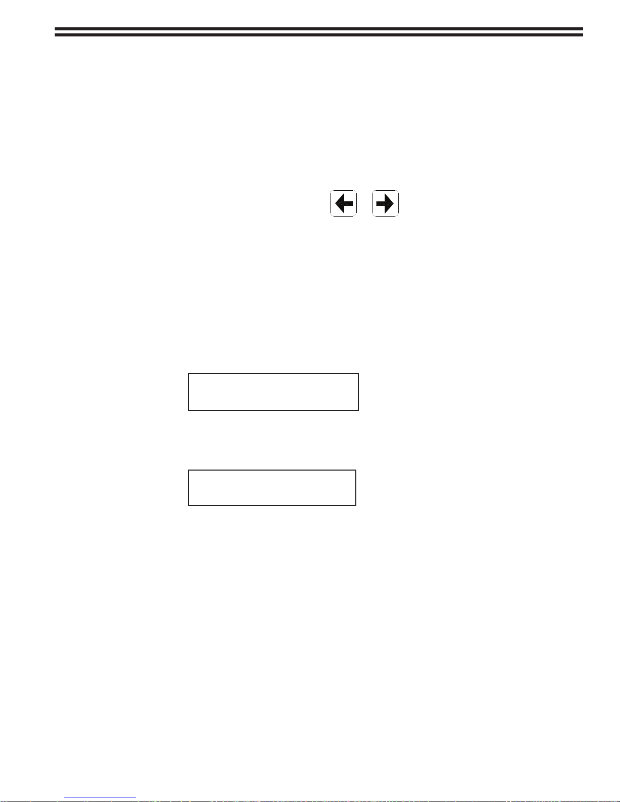
• MANUAL- Advance through the available channel display (if more than one
channel is active), including the 4-channel summary, by pressing the right or left
arrow keys.
• AUTO- Automatically scrolls through the available channels, advancing to the next
channel every 3 seconds, but skips the 4-channel summery
Two types of data displays are possible in the RUN mode:
• 4-channel Summary
• Single-channel Summary
When using the 4-channel summary display, each line is divided into two 10-character
groupings, one for each channel. This display mode is not available if the AUTO display
mode has been selected. Channel number, gas identification and instantaneous gas
concentration in ppm are displayed simultaneously as shown below:
1 CL 1.23 2 O3 45.6
3 CL 738 4 NH 0.12
The single-channel display mode shows the same data for the selected channel in addition
to the channel’s 10-character TAGNAME, short-term exposure limit and either time-weighted
average (TWA) or custom gas concentrations (depending on which has been selected).
A typical display is shown below:
CH1 TAGNAME 1.23
STEL: 4..56 TWA: 7.89
When in operation, the instrument selects the appropriate display mode using the following
guidelines:
Single-Channel Display a. If only one CHANNEL is active (refer to section 4.3.3.2)
b. If MANUAL mode is selected to show a single CHANNEL
c. During alarm if only one CHANNEL is active
4-Channel Summary a. If all CHANNELS are OFF
b. If MANUAL mode is selected to show the 4-CHANNEL
summary
c. During alarm if more than one channel is active.
If desired, the arrow keys may be used to select the
single-channel display mode to show information for the
CHANNEL in active alarm. If in single-channel mode, the
display reverts to the 4-channel summary mode if a
second alarm occurs.
- 23 - 325.6610.17
3.2.2.8 Watchdog Timer Circuit
The “watchdog” circuit is intended to let the operator know that the microprocessor has stopped
running. The circuit requires a constant input pulse from the microprocessor that only occurs
during proper operation. If the input pulses stop for more than a second, the watchdog circuit
will disable all of the relays and cause the display backlight to flash. In the event that this should
happen, restore normal operation by momentarily removing and re-applying AC power from
the unit thereby allowing the unit to cycle through its start-up procedure.
3.2.2.9 Self-Test
An optional self-test feature is available in the SETUP-CONFIGURE-INSTRUMENT-SELF TEST
menu item. This feature permits testing of the functional integrity of the receiver and some
of its electronics. This test causes the system to be checked for basic operation and proper
output. Once initiated, it operates automatically without further operator intervention (except
for the keypad test where user-action is required) as long as the appropriate data was entered
in the SETUP-CONFIGURE-INSTRUMENT-SELF TEST menu item.
The self-test sequence verifies that the unit is operating properly and is divided into two
sections:
• Standard - runs on all units
• Extended - requires entry of the Configuration Code (refer to section 3.2.2.9.2)
In SETUP, ALARMS, and DATA modes, gas-monitoring continues to
take place even though concentration values are not shown on the display.
However, when in SETUP, initiation of CALIBRATION, SELF-TEST or
SENSOR CHECK functions will temporarily suspend normal gas-monitoring.
CAUTION
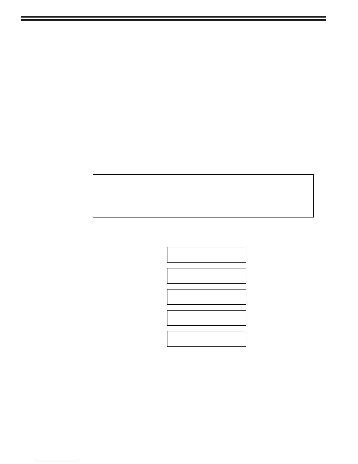
3.2.2.9.1 Standard Tests
The standard test sequence that is performed on all units is as follows:
SELF-TEST
DISPLAY
SELF-TEST
KEYPAD
SELF-TEST
NVRAM
SELF-TEST
RAM
SELF-TEST
DIGITAL OUTPUTS
The test runs automatically once initiated, however, user-action is required as the keypad
self-test is performed. The user is prompted to press the appropriate keypad buttons
in the sequence from upper left to lower right on the keypad. The display will indicate
which button is to be pressed. Once the keypad self-test is completed, the test will
resume automatic operation.
3.2.2.9.2 Extended Tests
In order for extended tests to be run on optional instrument configurations, a
CONFIGURATION CODE must be entered. The CONFIGURATION CODE indicates
the receiver’s configuration. The CONFIGURATION CODE must be entered in the
SETUP-CONFIGURE-INSTRUMENT-ENTER CONFIG CODE menu item prior to
325.6610.17 - 24 -
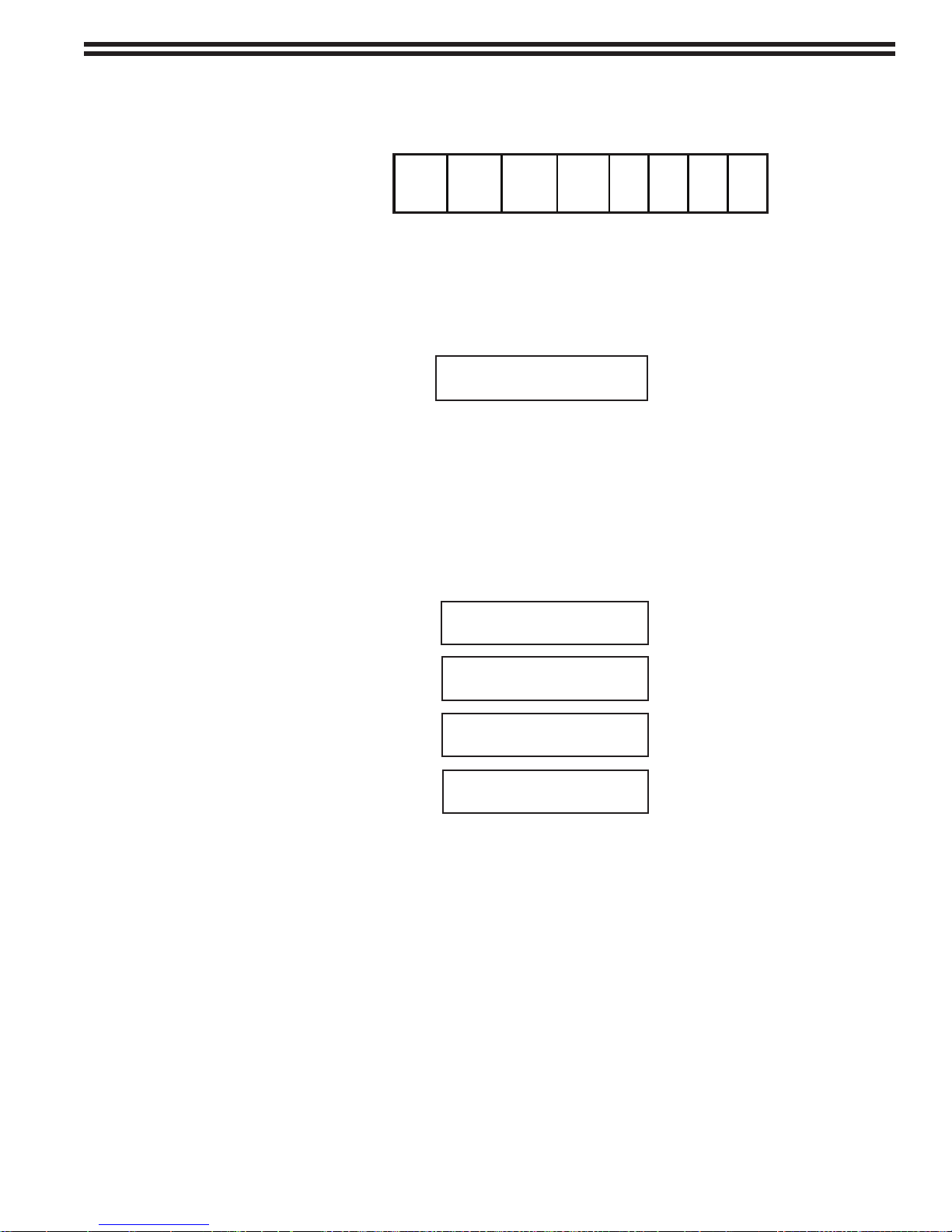
initializing the self-test procedure. It is an 8-digit code, with each digit being either 1
4 ANO 6DO
RS232/
RS485
Comm
Ext.
Battery
Kit
CH1 CH2 CH3 CH4
or 0, depending on whether an option is present or not. The positions of the digits to
be entered correspond to the options below:
To enter the proper configuration code, enter a “1” in the position corresponding to the
option if that option is present. (Be certain to enter only the digit “1”, any other entry
will be interpreted as a “0” by the system.) Enter a “0” if the option is not present.
For example, the CONFIGURATION CODE for a receiver with 4 analog outputs,
RS232 communication, and external battery kit, and 1 sensor connected to S1+ and
S1- terminals on the sensor interface TB3 (Refer to figure 2-3 or 2-4) is shown below:
ENTER CONFIG CODE
10111000
The last four entries in the CONFIGURATION CODE correspond to the sensor channels
in the instrument that have the ability to perform the optional SENSOR CHECK routine.
Entries in these positions are only required to run the sensor check (refer to section
3.2.2.10) and are not required for the SELF-TEST to function properly.
If the configuration code that has been entered indicates that the appropriate option
is present, the extended self-test routine will be performed in the following sequence:
NOTE: Rx and Tx need to be connected for communications ports self test to work.
ANALOG OUTPUTS
OPTL DIGITAL OUTPUTS
COMMUNICATIONS PORTS
3.2.2.9.3 Self-test Failure Messages
Most tests simply exercise the hardware and do not detect an error, and therefore, do
not generate an error message. The messages for the tests that do detect failure are
given below. The test will stop at a failure and wait to the ENTER key to be pressed in
order to proceed with the remaining tests.
The self-test may be run in two modes:
• Single
• Repeat
The SINGLE mode performs the SELF-TEST sequence only once, then returns the
unit to the RUN mode if no problems occurred.
SELF-TEST
SELF-TEST
SELF-TEST
SELF-TEST
BATTERY
- 25 - 325.6610.17
The REPEAT mode continues to cycle through the SELF-TEST sequence until terminated
by the operator. When in REPEAT mode, the DISPLAY and KEYPAD self-tests are only
performed during the first cycle and are skipped thereafter. In REPEAT mode, the
display indicates the number of successful passes through the self-test cycle. If an
error occurs while in REPEAT mode, the self-test will stop and the display will flash and
indicate the nature of the error and the cycle-number during which the error occurred,
as shown below:
NVRAM FAILURE
PASS COUNT = 3
RAM FAILURE
PASS COUNT = 3
COMM PORT FAIL
PASS COUNT = 3
BATTERY FAILURE
PASS COUNT = 3
The operator may record the error and continue the REPEAT mode by pressing the
ENTER key. At the end of each cycle, the user is given the option to exit the REPEAT
mode by pressing the ENTER key. This capability is indicated on the display as shown
below:
Normal sensor data-processing is interrupted when in the self-test mode, therefore it
is recommended that the use of the REPEAT mode be limited to isolating a suspected
problem area by testing it multiple times. Once the problem had been investigated or
confirmed, press ENTER to exit the SELF-TEST REPEAT mode.
3.2.2.10 Sensor Check
The Chloralert™ Plus includes an optional SENSOR CHECK feature that may be used to verify
the integrity of the sensor and its associated electronics. This check may only be performed on
channels that have been configured with the optional sensor check gas generator (refer to Parts
Lists 325.7603). The channels on which the check will be run must be selected by making the
appropriate entry in the last four digits of the configuration code (refer to section 3.2.2.9.2).
In order for the SENSOR CHECK to function properly, the sensor
CHANNEL must contain the optional SENSOR CHECK gas generator and the
sensor wired to S3+ and S3- on TB2, then the “1” entry in the CONFIGURATION
CODE must be placed in the “CH3” position, otherwise an error will result.
PRESS ENTER TO STOP
PASS COUNT = 21
NOTE
channel entries in the CONFIGURATION CODE must correspond to the
channels on the sensor interface terminal block (TB3) to which the
sensors are wired. For example, if a single-sensor system has its
The ten minute test consists of generating a test gas using the sensor check gas generator and
detecting the gas with the sensor. If the generated test-gas is detected within a certain concentration
range, the test is considered successful and the unit will automatically rever t to the RUN mode. The
sensor check test is valid whenever the background concentration exceeds 0.5 ppm.
325.6610.17 - 26 -
 Loading...