

Instruction Manual Series 1041B
CAPITAL CONTROLS
®
- 1 - 310.6002.0

These instructions describe the installation, operation and maintenance of the subject equipment. Failure to strictly follow
these instructions can lead to an equipment rupture that may cause signicant property damage, severe personal injury and
even death. If you do not understand these instructions, please call De Nora Water Technologies (DNWT), Inc. for clarication
before commencing any work at +1 215 997 4000 and ask for a Field Service Manager. De Nora Water Technologies, Inc.
reserves the rights to make engineering renements that may not be described herein. It is the responsibility of the installer
to contact DNWT Inc. for information that cannot be answered specically by these instructions.
Any customer request to alter or reduce the design safeguards incorporated into DNWT Inc. equipment is conditioned
on the customer absolving DNWT Inc. from any consequences of such a decision.
DNWT Inc. has developed the recommended installation, operating and maintenance procedures with careful attention to
safety. In addition to instruction/operating manuals, all instructions given on labels or attached tags should be followed.
Regardless of these eorts, it is not possible to eliminate all hazards from the equipment or foresee every possible hazard
that may occur. It is the responsibility of the installer to ensure that the recommended installation instructions are followed.
It is the responsibility of the user to ensure that the recommended operating and maintenance instructions are followed.
De Nora Water Technologies, Inc. cannot be responsible for deviations from the recommended instructions that may result in
a hazardous or unsafe condition.
DNWT Inc. cannot be responsible for the overall system design of which our equipment may be an integral part of or any
unauthorized modications to the equipment made by any party other than DNWT Inc.
DNWT Inc. takes all reasonable precautions in packaging the equipment to prevent shipping damage. Carefully inspect each
item and report damages immediately to the shipping agent involved for equipment shipped “F.O.B. Colmar” or to DNWT Inc.
for equipment shipped “F.O.B Jobsite”. Do not install damaged equipment.
De Nora Water Technologies Inc., COLMAR OPERATIONS
COLMAR, PENNSYLVANIA, USA
is ISO 9001: 2008 CERTIFIED
310.6002.0 - 2 -

Table of Contents
1 INTRODUCTION .......................................................................................... 4
1.1 General ......................................................................................................4
1.2 Specications ................................................................................................4
1.3 Automatic Switchover System Components ...................................................................4
1.4 Principle of Operation ........................................................................................4
2 INSTALLATION ........................................................................................... 8
2.1 Automatic Switchover Electronics ............................................................................8
2.2 Motorized Ball Valves Mounting ..............................................................................8
2.3 Pressure Switches ............................................................................................8
2.4 Electrical Connections ........................................................................................8
3 START-UP. . . . . . . . . . . . . . . . . . . . . . . . . . . . . . . . . . . . . . . . . . . . . . . . . . . . . . . . . . . . . . . . . . . . . . . . . . . . . . . . . . . . . . . . . . . . . . . . 9
3.1 General ......................................................................................................9
3.2 Leak Testing. . . . . . . . . . . . . . . . . . . . . . . . . . . . . . . . . . . . . . . . . . . . . . . . . . . . . . . . . . . . . . . . . . . . . . . . . . . . . . . . . . . . . . . . . . . . . . . . .10
4 OPERATION ............................................................................................. 11
4.1 General .....................................................................................................11
4.2 Indicators ...................................................................................................11
4.2.1 Automatic Mode .....................................................................................11
4.2.2 Manual Override Mode ...............................................................................13
4.2.3 Empty Indications ....................................................................................13
4.2.4 Closed Indications ....................................................................................13
4.2.5 Emergency Shutdown/Failure Indications .............................................................14
5 SERVICE ................................................................................................15
5.1 Automatic Switchover ......................................................................................15
5.2 System Shutdown for Routine Maintenance ..................................................................15
5.3 Expansion Chamber Rupture Disc Replacement (Liquid System Only) .........................................16
5.4 PLC Reset Instructions .......................................................................................16
5.5 PLC Fault (Blinking Red Light) ................................................................................16
6 TROUBLESHOOTING CHART .............................................................................17
FIGURES
1 Automatic Switchover Unit Faceplate .........................................................................5
2 Automatic Switchover System - Gas Withdrawal ...............................................................6
3 Automatic Switchover System - Liquid Withdrawal ............................................................7
4 Programmable Controller Indicators ..........................................................................9
- 3 - 310.6002.0

1 INTRODUCTION
1.1 General
These instructions apply to the Series 1041 and 1041B Automatic Switchover control units. Instruction manuals for
other system components and supplemental data are referenced where applicable.
The Series 1041 Automatic Switchover model number describes the basic design as follows:
MODEL 1 0 4 1 (B)
Design/Inspection
01 - Standard
02 - Special Requirements
Power Requirements
01 - 120 Vac, 50/60 Hz, single phase
02 - 240 Vac, 50/60 Hz, single phase
1.2 Specications
Operation: Automatic switchover with manual override
Control: Programmable logic controller
Field Inputs: 24 Vdc source supplied
Field Outputs: 5/10 amps at 120 Vac, resistive load
Control Selector Switches: Mode (Auto/Manual), Side A (Open/Closed), Side B (Open/Closed), Reset
Control Panel Design: Graphic mimic panel
Control Indicators: Steady state or ashing indicators (Empty, Open, Closed, Stand-by) for Side A and Side B
Flashing Indicators: Valve action, operator error, switchover malfunction, remote shutdown
Failure Alarms: Field congurable
Safety Features: Safety interlocks, latching alarm circuit with manual reset, automatic remote shutdown
Power Requirements: 120 Vac or 240 Vac, 50/60 Hz, single phase
Shipping Weight: 45 lbs (20 kgs)
Enclosure: NEMA 4X
Switches: NEMA 4X, industrial grade
Mounting: Wall
1.3 Automatic Switchover System Components - See Figures 1, 2 and 3
The Series 1041 Automatic Switchover System consists of the automatic switchover electronics unit with
programmable logic controller, a pressure switch and a motorized ball valve for each source, liquid expansion
chambers with rupture discs to protect liquid pipelines from hydrostatic rupture if liquid is switched, and optional
manifolds and manifold bypass valves when gas is switched. Pressure switches, motorized ball valves, expansions
chambers and manifolds are specic to the gas or liquid being dispensed.
1.4 Principle of Operation
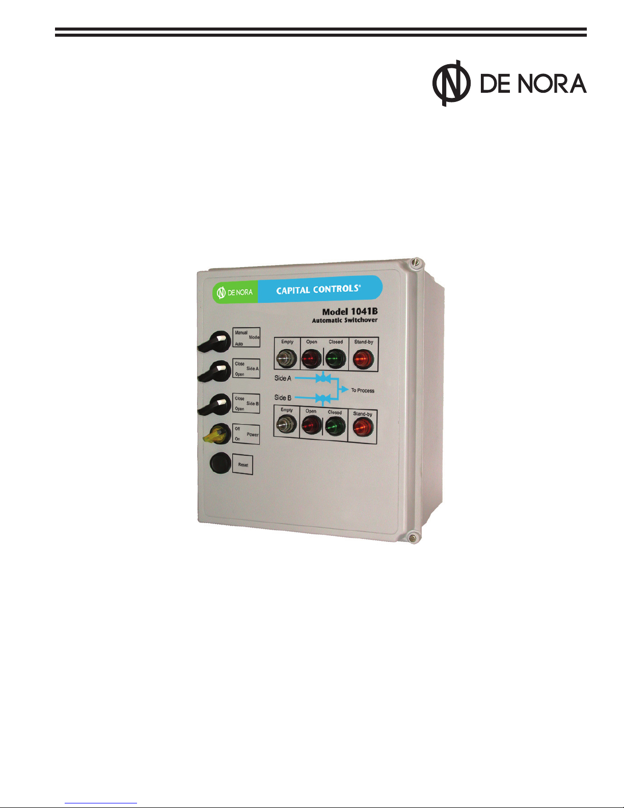
The Series 1041B Automatic Switchover System provides for automatic switching with manual override between two
independent sources of liquid or gas chemical assuring an uninterrupted supply of chemical to liquid vaporizing or
gas feed equipment.
The automatic switchover system is suitable for pressure or vacuum operation.
310.6002.0 - 4 -
Automatic switchover is initiated by low pressure (high vacuum) of the on-line source and resulting switch closure.
The mechanical limit switch in each motorized ball valve actuator is adjusted to transfer when the valve reaches the
closed position. When the controller senses a limit switch closure, it opens the motorized ball valve on the stand-by
source. The automatic switchover design uses the mechanical limit switches to prevent either motorized ball valve
from opening before the other motorized ball valve is completely closed.
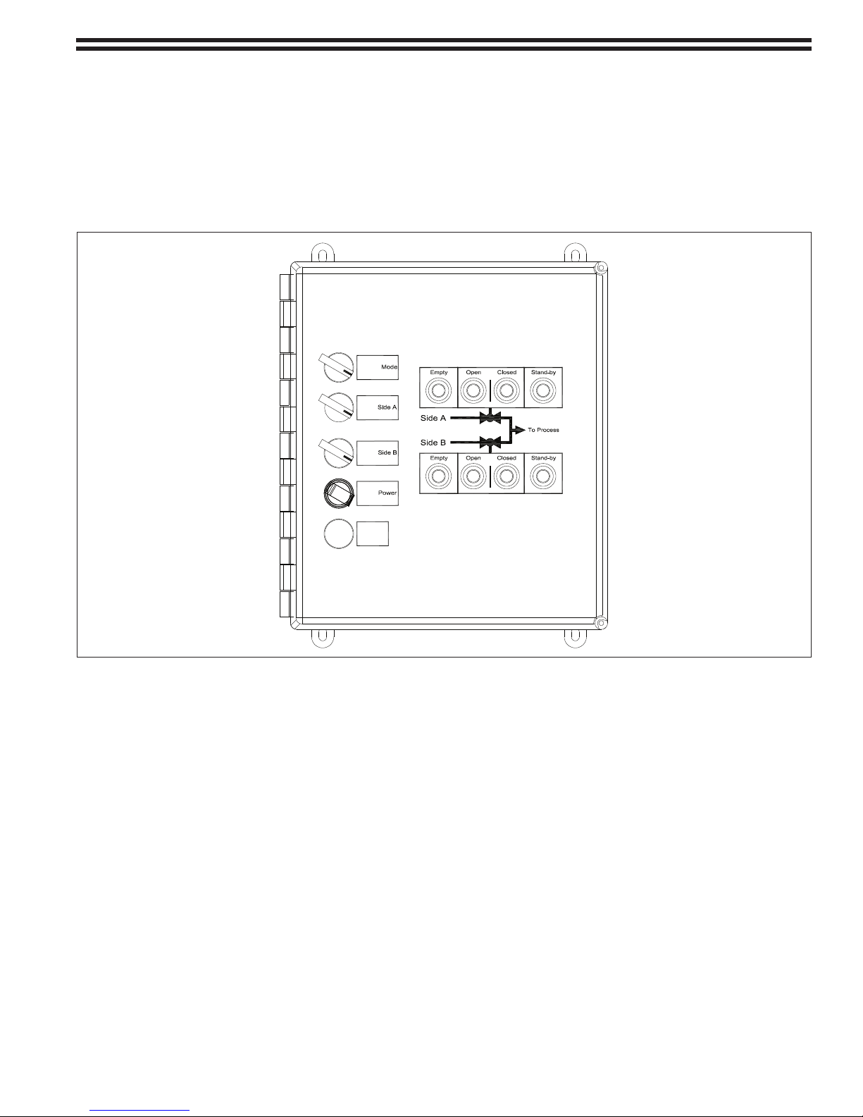
Manual override is accomplished by selecting the manual mode using the Auto/Manual selector switch, then
manually opening or closing the desired valve using the Side A or Side B, Open/Closed selector switches.
Manual
Auto
Close
Open
Close
Open
W
Off
On
W
G AR
AGR
Reset
Figure 1 - Series 1041B Automatic Switchover Unit Faceplate
- 5 - 310.6002.0
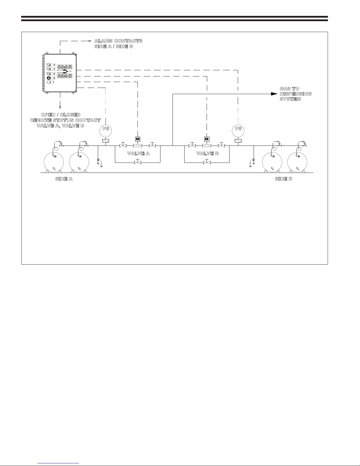
NOTE: Gas supply may be cylinders, ton container or a combination of both. All containers in use must be at the same
PS PS
ALARM CONTACTS
SIDE A / SIDE B
OPEN / CLOSED
REMOTE STATUS CONTACT
VALVE A, VALVE B
VALVE A VALVE B
SIDE A SIDE B
Auto
Open
Manual
Open
Close
Close
Reset
SYSTEM
DISPENSING
GAS TO
On
Off
temperature.
Gas Service Components:
Automatic switchover controller (120 Vac or 240 Vac)
3/4" Manual valve
3/4" Valve with motorized operator
Pressure switch with diaphragm protector (Range: 5-30 psig)
NOTE: Manifolds are required for cylinder or ton container withdrawal.
Figure 2 - Automatic Switchover System - Gas Withdrawal
310.6002.0 - 6 -

NOTE: Liquid supply shall be ton containers. All containers in use must be at the same temperature and elevation.
PS
PS
ALARM CONTACTS
SIDE A / SIDE B
OPEN / CLOSED
REMOTE STATUS CONTACT
VALVE A, VALVE B
VALVE A VALVE B
SIDE A SIDE B
PI PSH
PSHPI
PSHPI
LIQUID
TO VAPORIZER
Reset
Close
Close
Open
Manual
Open
Auto
On
Off
Liquid Service Components:
Automatic switchover controller (120 Vac or 240 Vac)
Liquid expansion chamber with rupture disc, pressure indicator and pressure switch (chlorine or sulfur dioxide)
1" Valve with motorized operator
Pressure switch with diagragm protector (Range 5-30 psig) (chlorine or sulfur dioxide)
NOTE: Liquid withdrawal manifolds are required.
Figure 3 -Automatic Switchover System - Liquid Withdrawal
- 7 - 310.6002.0

2 INSTALLATION
2.1 Automatic Switchover Mounting
2.1.1 The Automatic Switchover electronics unit may be wall mounted indoors or in a protected outdoor location
using the corrosion-resistant wall mounting feet provided. Choose a location free from vibration. Care should
be taken when installing conduit to ensure rainwater, condensation or other contaminants do not enter the
enclosure. See Bulletin 310.1003 for dimensions.
2.1.2 Insert the mounting feet on the automatic switchover enclosure.
2.1.3 Position the enclosure at the desired height and scribe a bolt hole circle through each of the mounting feet.
2.1.4 Drill the proper size holes for the bolts or wall anchors selected. Four (4)1/4” bolts or equal size wall anchors
are recommended.
2.2 Motorized Ball Valves
The motorized ball valves should be installed in the same area as the liquid/gas source.
2.2.1 The motorized ball valves are provided with 1" NPT (liquid system) or 3/4"NPT (gas system) inlet and outlet
connections.
2.2.2 Recommended piping suitable for the liquid or gas must be used. Refer to The Chlorine Institute Pamphlet
No. 6 which recommends that Schedule 80 piping fabricated from ASTM A-106 Grade A or B steel and 3000
pound, A-105 Grade No 1 or 2 forged steel ttings be used for chlorine liquid or gas service.
For chemicals other than chlorine, consult appropriate directory recommendations on pipe and ttings for
the chemical being dispensed.
2.2.3 All threaded connections for chlorine must be sealed with litharge and glycerin or Teon tape. Litharge and
glycerin sealed connections cannot be disassembled after the sealant hardens.
2.3 Pressure Switches
2.3.1 The pressure switches should be installed vertically above the piping system upstream of the motorized ball
valves, level with the horizontal plane and in the same area as the liquid/gas source.
2.3.2 All threaded connections for chlorine must be sealed with litharge and glycerin or Teon tape. Litharge and
glycerin sealed connections cannot be disassembled after the sealant hardens.
NOTE: Pressure switches a factory adjusted to actuate at 15 psig upon decreasing pressure.
2.4 Electrical Connections
The Automatic Switchover electronics unit houses a programmable logic controller, indicating lights, and controls for
automatic or manual override system operation. All external components are wired directly to the unit. Refer to the
wiring diagram Bulletin 310.3012.
Recommended wire size for interconnecting the automatic switchover and components is #14 AWG.
To avoid equipment and system damage, ensure power is supplied to all equipment.
CAUTION
310.6002.0 - 8 -

3 STARTUP
3.1 General
The manual valves on each of the liquid or gas sources should not be opened until both motorized ball valves are
electrically closed and calibrated and all leak tests have been successfully completed.
3.1.1 To electrically close both motorized ball valves proceed as follows:
a. Set the mode switch to MANUAL.
b. Set Side A and Side B switches to CLOSE.
c. Both motorized ball valves should close and both CLOSE lights should illuminate.
d. Verify eld inputs and outputs from the programmable controller. See Figure 4
3.1.2 Valve A and Valve B Motorized Valves must be calibrated as follows
a. Check the limit switches for 100% closed contact closure.
b. Enter the CALIBRATE mode by depressing and holding the RESET push-button until all indicators
illuminate and the EMPTY/OPEN indicators go out (approximately 10 seconds). Calibrate mode is now
activated.
c. Cycle Valve A to the full open position by setting Side A switch to OPEN and then cycle to full close by
setting Side A switch to CLOSE.
d. Repeat open and close cycle for Valve B.
e. Set the mode switch to AUTO, then to MANUAL to reset the calibrate mode.
COMM2
COMM1
COMM0
DCOMM
BAT.LO
U-DISP
POWER
RUN
FAULT
FORCE
1400
Figure 4 - Programmable Controller I/O Status Indicators
- 9 - 310.6002.0

3.2 Leak Testing
3.2.1 Air/Nitrogen Pressure Leak Testing
a. The piping system upstream and downstream of the motorized ball valves must be checked pressurizing
the piping with 150 psi dry air or nitrogen and applying soapy water to the outside of all pipe joints and
ttings. The two motorized ball valves should remain closed during this leak check.
b. Repair all leaks and re-test. If no leaks are apparent, bleed-o and remove the dry air or nitrogen
pressure source.
3.2.2 Chemical Leak Testing Upstream of Motorized Ball Valve
After a successful pressure test with nitrogen or air, check for leaks in the piping system with the actual
chemical to be dispensed.
NOTE: Household ammonia (stronger ammonia solution may also be used) is used to detect chlorine or
sulfur dioxide leaks. Household chlorine bleach (sodium hypochlorite solution) is used to detect ammonia
leaks.
To check for leaks, use a plastic squeeze bottle about 1/4 full of the leak test solution. Squeeze the
bottle while directing the fumes below all joints and ttings. The appearance of a dense white smoke
indicates a leak.
NOTE: Whether the automatic switchover system is designed for switching sources of liquid or gas, a source
of gas rather than liquid is used for leak testing.
To check for leaks, proceed as follows:
a. Open and immediately close the container gas outlet valve introducing just enough gas to pressurize
the rst section of the piping between the source and its respective closed motorized ball valve.
NOTE: All other valves should be open to evacuate the system through the gas feed system downstream
should a leak be detected.
b. Check each joint, connection and tting by applying fumes below each connection. Use the gas feed
system downstream to evacuate the system before repairing leaks and re-testing.
3.2.3 Chemical Leak Testing Downstream of Motorized Ball Valve
a. Pressurize the piping system downstream of the Side A motorized ball valve by setting the Side A switch
to OPEN. The OPEN indicator light for Side A will illuminate indicating that the side a motorized ball
valve has opened.
b. With gas present upstream of the valve, opening the valve pressurizes the piping downstream.
c. Close the Side A valve by setting the Side A switch to CLOSE. The CLOSE indicator light for Side A will
illuminate indicating that the Side A motorized ball valve has closed. Leak check all piping, joints and
ttings downstream of the motorized ball valve. Repair all leaks and re-test.
d. Repeat procedure for Side B.
310.6002.0 - 10 -

4 OPERATION
4.1 General
The Series 1041 & 1041A Automatic Switchover Systems are totally automatic systems with manual override. In the
automatic mode, the system dispenses liquid or gas from the on-line source. When the on-line source is depleted,
the system will automatically switchover and dispense from the stand-by source. Manual mode switching is done by
manually opening and closing the motorized ball valves. Whether in automatic or manual mode, the system design
prevents both motorized ball valves from being open at the same time.
4.2 Indicators
In this section, indicator lights are symbolized as follows:
O =OFF, • = ON, * = Flashing, — = Disregard
4.2.1 Automatic Mode
a. Initially, both motorized ball valves should be closed and each side in stand-by.
Side Empty Open Closed Stand-by
A O O
B O O
Both valves closed and both sides in stand-by
b. Open the manual valves on each liquid or gas source.
•
•
•
•
c. Initiate automatic switchover by setting the mode switch to AUTO and depress and hold the
RESET push-button until all the indicators go on. Valve A will open as indicated by the side A
illuminated OPEN indicator while Valve B remains closed and Side B remains in stand-by.
Side Empty Open Closed Stand-by
A O O O
B O O
Valve A open and Side A feeding. Side B in stand-by.
d. When the Side A on-line source is depleted, the EMPTY light for Side A illuminates and feed transfers
automatically to Side B.
e. Valve A closes as indicated by a ashing CLOSED light while Valve B remains closed and Side B remains
in stand-by.
Side Empty Open Closed Stand-by
A O
B O O
Valve A empty and Valve A closing. Side B remains in stand-by.
f. Only when Valve A is completely closed does Valve B open with feed now from Side B.
Side Empty Open Closed Stand-by
A O O
B O O O
Side A empty and Valve A closed. Valve B opens and Side B feeding.
•
•
•
•
*
•
•
O
•
•
•
- 11 - 310.6002.0

g. After Side A’s chemical has been replenished, EMPTY and STAND-BY lights ash indicating Side A
source has been replaced.
Side Empty Open Closed Stand-by
A
B O O O
Side A source has been replenished.
h. The operator depresses RESET push-button completing side A source replenishment and placing side
A source in stand-by status for subsequent automatic switchover to Side A source when Side B on-line
source becomes depleted.
Side Empty Open Closed Stand-by
A O O
B O O O
Valve B open and side B feeding. Side A in stand-by.
i. When the side B on-line source is depleted, the EMPTY light for Side B illuminates and feed transfers
automatically to Side A.
j. Valve B closes as indicated by the ashing CLOSED light while Valve A stays closed and Side A
remains in stand-by.
Side Empty Open Closed Stand-by
A O O
B O
Side B empty and Valve B closing. Side A remains in stand-by.
*
•
O
•
*
•
•
•
•
•
*
•
O
k. Only when Valve B is completely closed does Valve A open now feeding from Side A.
Side Empty Open Closed Stand-by
A O O O
B O O
Side B empty and Valve B closed. Valve A open and Side A feeding.
l. Side B source is replaced. EMPTY and STAND-BY lights ash indicating Side B source has been replaced.
Side Empty Open Closed Stand-by
A O O O
B
Side B source has been replaced.
m. The operator depresses RESET push-button completing Side B source replenishment and putting Side
B source in stand-by status for subsequent automatic switchover to Side B source when Side A on-line
source becomes depleted.
Side Empty Open Closed Stand-by
A O O O
B O O
Valve A open and Side A feeding. Side B in stand-by.
•
*
•
•
•
O
•
*
•
•
•
310.6002.0 - 12 -

4.2.2 Manual Override Mode
a. To place the automatic switchover into manual override with Side A source on-line set Side A switch to
OPEN, then set the mode switch to MANUAL.
Side Empty Open Closed Stand-by
A O O O
•
B O O
Valve A open and Valve B closed. Side B in stand-by.
b. To place the automatic switchover into manual override with Side B source on-line set Side B switch to
OPEN and Side A switch to CLOSE, then set the mode switch to MANUAL.
Side Empty Open Closed Stand-by
A O O
B O O
Valve A closing. Side B in stand-by.
Side Empty Open Closed Stand-by
A O O
B O O O
Valve B open and Valve A closed and Side A in standy-by.
4.2.3 EMPTY Indications
a. When Side A is manually on line and Side A source is depleted, the EMPTY light for Side A will ash.
Side Empty Open Closed Stand-by
•
*
•
•
•
O
•
•
•
A
B O O
Valve A open and Side A empty. Side B in stand-by.
Side Empty Open Closed Stand-by
A O O
B
Valve B open and Side B empty. Side A in stand-by.
4.2.4 CLOSED Indications
Side Empty Open Closed Stand-by
A O O
B O O
O mode - both valves closed and both sides in stand-by.
*
*
•
•
O O
•
•
O O
•
•
•
•
•
•
- 13 - 310.6002.0

4.2.4 CLOSED Indications (cont.)
Side Empty Open Closed Stand-by
A O O
B O O
Side A and Side B sources empty and both valves closed.
Side Empty Open Closed Stand-by
A O
B O
Side A and Side B sources empty - system shutdown. Requires manual reset to initiate automatic
mode.
4.2.5 Emergency Shutdown/Failure Indications
Side Empty Open Closed Stand-by
A O O
B O O
Remote shutdown of both valves - automatic switchover is connected to external alarm devices
such as gas, re or smoke detectors.
•
•
•
•
•
•
•
•
•
•
*
*
*
*
Side Empty Open Closed Stand-by
A
B
Valve A failure, limit switch open, system halted.
Side Empty Open Closed Stand-by
A
B
Valve B failure, limit switch open, system halted.
Side Empty Open Closed Stand-by
A O O O O
B O O O O
Re-powering requiring manual reset, check power, fuse. If condition persists, contact
De Nora Water Technologies Service Department.
* *
* *
310.6002.0 - 14 -

5 SERVICE
To perform routine maintenance on system components, De Nora Water Technologies recommends closing the
manual line valves at the two independent chemical sources while continuing system operation to evacuate the
piping system of chemical. Such routine maintenance might include cleaning lters and vaporizers, and pressure
reducing valve repair.
5.1 Automatic Switchover
The Automatic Switchover electronics unit does not require routine maintenance.
5.1.1 Power Supply
a. The Automatic Switchover unit uses a fuse on incoming power and 24 Vac output power that can be
replaced.
b. The programmable controller displays power status on the front panel. If the programmable controller
displays a fault (see Figure 4), contact De Nora Water Technologies Service Department.
NOTE: Recording of indicators (see Figure 4) is very helpful in troubleshooting faults.
c. Control relays interface with the motorized ball valves and can be replaced if found faulty during service
and/or troubleshooting.
5.2 System Shutdown for Routine Maintenance
In addition to the following, refer to the manufacturers instruction manual for routine maintenance.
5.2.1 Complete System Shutdown for Maintenance
a. Continue dispensing system operation to evacuate the piping system of the liquid/gas being dispersed.
b. Close the manual line valves at the two independent chemical sources while continuing system
operation to evacuate the piping system of chemical.
c. Observe the system status lights on the Automatic Switchover. The OPEN light of the side which is
dispensing chemical will eventually go out and the EMPTY light on that side will illuminate indicating
that chemical between the source and the motorized ball valve has been exhausted. Automatic
switchover will occur and the chemical in the stand-by source will also be exhausted between the
source and the motorized ball valve. Both EMPTY lights should be illuminated and both motorized ball
valves closed.
d. Turn OFF power to the Automatic Switchover electronics.
e. Continue operating the chemical dispensing equipment as long as necessary to evacuate chemical from
the entire system.
NOTE: In the case of vacuum type solution feed gas feeders, continue operating the gas feeder until
the oat in the gas owmeter drops to the bottom of the tube indicating no gas available. Turn OFF the
water supply to the ejector.
f. Open all safety switches and circuit breakers supplying electrical power to the system.
CAUTION: The piping may still contain some potentially hazardous residual gas which should be
exhausted to a safe area.
5.2.2 Return to automatic operation.
a. Check any piping connections that have been disassembled for leaks before opening chemical source
manual valves. (Refer to sections 3.2.1, 3.2.2, and 3.2.3)
b. Apply power to the system.
c. Set mode switch to AUTOMATIC. (Refer to section 4.2.1)
- 15 - 310.6002.0

5.3 Expansion Chamber Rupture Disc Replacement (Liquid Systems Only)
5.3.1 Ensure the expansion chamber and manifold lines in the aected area are free of chemical.
5.3.2 Without removing the expansion chamber, loosen the nuts on the four (4) studs so the halves of
the safety head can be separated approximately 1”. Lift the chamber and place a piece of wood
between the safety head top and bottom to keep them separated.
5.3.3 Remove the damaged rupture disc and make a careful inspection of the seating area of the safety
head. If the seat is dirty or tarnished, clean with a soft cloth. If it is nicked or scratched, replace the
safety head. Do not attempt to polish out deep marks.
5.3.4 Grasping the new rupture disc by the name tag, insert into the bottom half of the safety head.
The convex (dome shaped) side of the rupture disc should face the expansion chamber.
5.3.5 Lower the upper half of the safety head and tighten all nuts evenly.
5.4 PLC Reset Instructions
Sometimes a reset of the PLC is required, please follow these instructions.
5.4.1 Conrm that PLC terminal 18 LED is illuminated (indicates 24 volt supply is operational).
If no LED, check the 24V fuse.
5.4.2 Power down PLC.
5.4.3 Install a jumper between terminals 18 & 19 of the PLC. The jumper allows the controller to disregard
all inputs and resets the valve timing delay to 15 seconds.
5.4.4 Reapply power to the PLC. Allow the system to run through the initial start up and self-test.
5.4.5 Run through calibration instructions. See Section 3.1.2 in this instruction manual Be sure to allow
the 15 seconds for the valve to time out. For example: cycle “A” to open, wait 15 seconds then
cycle “A” to close, wait 15 seconds.
5.4.6 Shut o the power; remove the jumper on terminals 18 & 19.
5.4.7 Restore the power to the PLC.
5.4 PLC Fault (Blinking Red Light)
5.5.1 To reset – press ESC from MENU.
5.5.2 Arrow down to MODE SWITCH.
5.5.3 Press OK.
5.5.4 Arrow to PROGRAM.
5.5.5 Press OK.
5.5.6 Arrow to RUN.
5.5.7 Press OK.
5.5.8 Fault should clear, RUN light should illuminate.
If condition persists, contact De Nora Water Technologies Service Department.
310.6002.0 - 16 -

6 TROUBLESHOOTING CHART
TROUBLE PROBABLE CAUSE CORRECTIVE ACTION
1. All Control indicators are not
illuminated.
2. One or more control
indicators are not
illuminated during lamp test.
3. Programmable controller
indicators not illuminated.
(See Figure 4)
4. Programmable controller
shows “FAULT”
(See Figure 4)
5. Field devices do not open or
close
a. Power supply failure at
source.
b. Blown fuse.
a. Indicator failure. a. Replace indicator.
a. Power supply failure at
source.
b. Blown fuse.
c. Programmable controller
failure
a. Program error
b. 24 Vac power supply failure
- input 18 not energized.
(See Figure 4)
a. Relay failure.
b. Limit switches not calibrated
for proper input signals.
a. Check and reset circuit
breaker.
b. Replace fuse.
a. Check and reset breaker.
b. Replace fuse.
c. Replace programmable
controller.
a. Consult factory for program
instructions.
b. Internal fuse blown, replace
controller.
a. Replace relay.
b. Adjust limit switches (Refer to
manufacturer’s instruction
manual.)
- 17 - 310.6002.0

Design improvements may be made without notice.
Represented by:
De Nora Water Technologies
3000 Advance Lane Colmar, PA 18915
ph +1 215 997 4000 • fax +1 215 997 4062
web: www.denora.com
mail: info.dnwt@denora.com
OCT 2017
310.6002.0 - 18 -
®Registered Trademark. © 2017. All Rights Reserved.
 Loading...