

Page 1
B
BAND
PHONES
VOLUME
ON / STANDBY
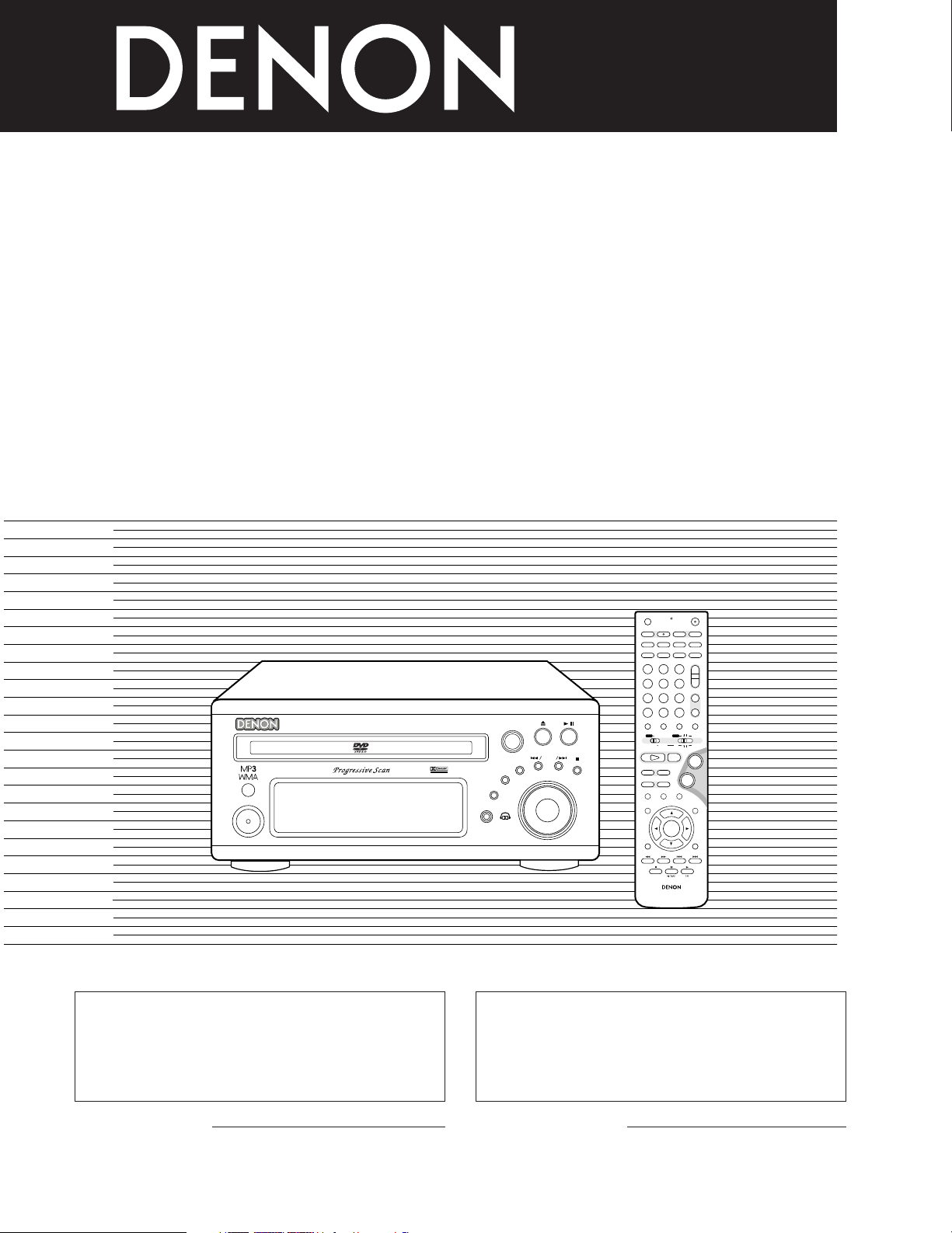
DVD SURROUND RECEIVER ADV-M71
TONE/ SDB
FUNCTION
MENU/SET
+
-
SURROUND/ SELECT
PUSH - PARAM.
VIRTUAL SPEAKER
+
-
+
-
RC-936
A / V
3
A-B REPEAT
SEARCH MODE
ONOFF
REPEAT RANDOM
CLEAR ZOOMSLIDE MODE
PROG/DIRECT
MEMO BANDMODE
STATUS
RETURN
ANGLE AUDIO
SUB TITLE
SETUP TONE/SDB
FUNCTIONSURROUNDINPUT MODETEST TONE
DVD
TUNER
CH
3
-
+
21
654
987
0
/
10
CALL
ENTER
MUTING
+
10
DISPLAY MENU
TOP MENU
SYSTEM MD
CDR TAPE
TUNER TV / VCR
SURROUND
PARAMETER
CH SELECT
VCR
NTSC/PAL
SLEEP
ENTER
CD SRS
EDIT/MENUCHARAC.
REC
TIMETITLE
TUNING /
TV VOL
TV CH TV CH
TUNERDVD
MD/LINE-1
TAPE/LINE-2
AUTO DECODE
VIRTUALDIRECT
5CH STEREO
STEREO
D.AUX
-
+
VCR CH
IN/SURR.
IN/SURR.
DVD
T VTV INSOURCE
+
-
9
8
21
76
DVD SURROUND SYSTEM
D-M71DVS
DVD SURROUND RECEIVER
ADV-M71
OPERATING INSTRUCTIONS
MODE D’EMPLOI
FOR ENGLISH READERS PAGE 4 ~ PAGE 111 POUR LES LECTEURS FRANCAIS PAGE 112 ~ PAGE 219
We greatly appreciate your purchase of this unit.
2
To be sure you take maximum advantage of all the
2
features this unit has to offer, read these instructions
carefully and use the set properly. Be sure to keep this
manual for future reference should any questions or
problems arise.
“SERIAL NO.
PLEASE RECORD UNIT SERIAL NUMBER ATTACHED TO
THE REAR OF THE CABINET FOR FUTURE REFERENCE”
Nous vous remercions pour l’achat de cet appareil.
2
Pour être sûr de profiter au maximum de toutes les
2
caractéristiques qu’offre cet appareil, lire avec soin ces
instructions et bien utiliser l’appareil. Toujours
conserver ce mode d’emploi pour s’y référer
ultérieurement en cas de question ou de problème.
“NO. DE SERIE
PRIERE DE NOTER LE NUMERO DE SERIE DE L’APPAREIL
INSCRIT A L’ARRIERE DU COFFRET DE FAÇON A POUVOIR
LE CONSULTER EN CAS DE PROBLEME.”
Page 2
SAFETY PRECAUTIONS
2
WARNING:
TO PREVENT FIRE OR SHOCK HAZARD, DO NOT
EXPOSE THIS APPLIANCE TO RAIN OR MOISTURE.
This device complies with Part 15 of the FCC Rules. Operation is subject to
the following two conditions: (1) This device may not cause harmful
interference, and (2) this device must accept any interference received,
including interference that may cause undesired operation.
This Class B digital apparatus meets all requirements of the Canadian
Interference-Causing Equipment Regulations.
CAUTION
RISK OF ELECTRIC SHOCK
DO NOT OPEN
CAUTION:
TO REDUCE THE RISK OF ELECTRIC SHOCK, DO
NOT REMOVE COVER (OR BACK). NO USERSERVICEABLE PARTS INSIDE. REFER SERVICING
TO QUALIFIED SERVICE PERSONNEL.
The lightning flash with arrowhead symbol, within an
equilateral triangle, is intended to alert the user to the
presence of uninsulated “dangerous voltage” within the
product’s enclosure that may be of sufficient magnitude
to constitute a risk of electric shock to persons.
The exclamation point within an equilateral triangle is
intended to alert the user to the presence of important
operating and maintenance (servicing) instructions in
the literature accompanying the appliance.
CAUTION
TO PREVENT ELECTRIC SHOCK, MATCH WIDE
BLADE OF PLUG TO WIDE SLOT, FULLY INSERT.
ATTENTION
POUR ÉVITER LES CHOCS ÉLECTRIQUES,
INTERODUIRE LA LAME LA PLUS LARGE DE LA
FICHE DANS LA BORNE CORRESPONDANTE DE
LA PRISE ET POUSSER JUSQU’ AU FOND.
Cet appareil numérique de la classe B respecte toutes les exigences du
Règlement sur le matériel brouilleur du Canada.
CAUTION:
1. Handle the power supply cord carefully
Do not damage or deform the power supply cord. If it is damaged or
deformed, it may cause electric shock or malfunction when used.
When removing from wall outlet, be sure to remove by holding the plug
attachment and not by pulling the cord.
2. Do not open the top cover
In order to prevent electric shock, do not open the top cover.
3. Do not place anything inside
Do not place metal objects or spill liquid inside the DVD video player.
Electric shock or malfunction may result.
NOTE:
This DVD video player uses the semiconductor laser. To allow you to enjoy
music at a stable operation, it is recommended to use this in a room of 5
°C (41 °F) ~ 35 °C (95 °F).
Copyrights
It is prohibited by law to reproduce, broadcast, rent or play discs in
2
public without the consent of the copyright holder.
NOTE ON USE / OBSERVATIONS RELATIVES A L’UTILISATION
2
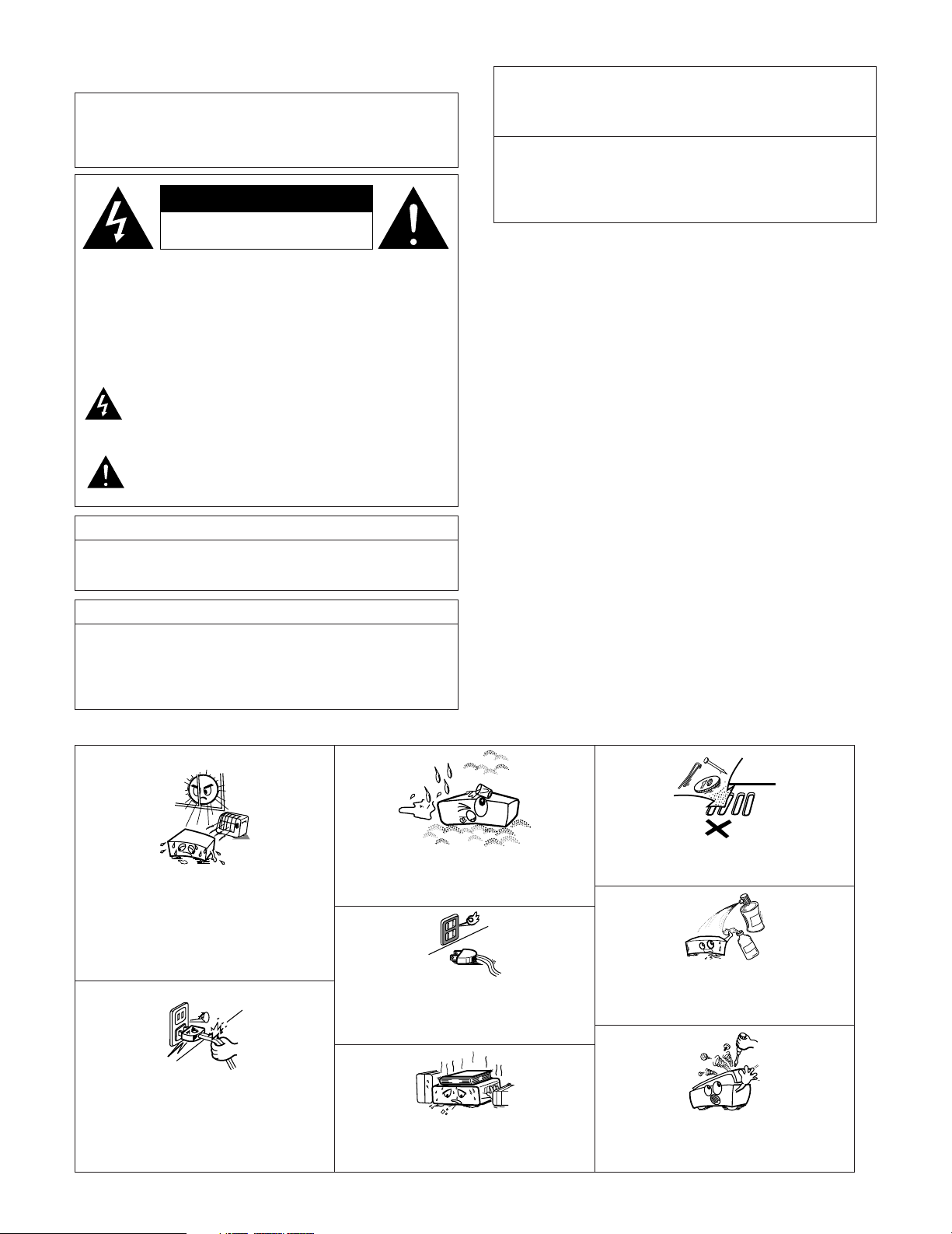
• Keep the set free from moisture, water, and
dust.
• Avoid high temperatures.
Allow for sufficient heat dispersion when
installed on a rack.
• Eviter des températures élevées
Tenir compte d’une dispersion de chaleur
suffisante lors de l’installation sur une étagère.
• Handle the power cord carefully.
Hold the plug when unplugging the cord.
• Manipuler le cordon d’alimentation avec
précaution.
Tenir la prise lors du débranchement du cordon.
• Protéger l’appareil contre l’humidité, l’eau et
lapoussière.
• Unplug the power cord when not using the set
for long periods of time.
• Débrancher le cordon d’alimentation lorsque
l’appareil n’est pas utilisé pendant de longues
périodes.
* (For sets with ventilation holes)
• Do not obstruct the ventilation holes.
• Ne pas obstruer les trous d’aération.
• Do not let foreign objects in the set.
• Ne pas laisser des objets étrangers dans
l’appareil.
• Do not let insecticides, benzene, and thinner
come in contact with the set.
• Ne pas mettre en contact des insecticides, du
benzène et un diluant avec l’appareil.
• Never disassemble or modify the set in any
way.
• Ne jamais démonter ou modifier l’appareil
d’une manière ou d’une autre.
2
Page 3
SAFETY INSTRUCTIONS
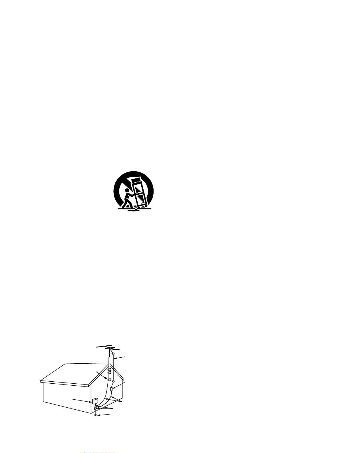
FIGURE A
EXAMPLE OF ANTENNA GROUNDING
AS PER NATIONAL
ELECTRICAL CODE
ANTENNA
LEAD IN
WIRE
GROUND
CLAMP
ELECTRIC
SERVICE
EQUIPMENT
ANTENNA
DISCHARGE UNIT
(NEC SECTION 810-20)
GROUNDING CONDUCTORS
(NEC SECTION 810-21)
GROUND CLAMPS
POWER SERVICE GROUNDING
ELECTRODE SYSTEM
(NEC ART 250, PART H)
NEC - NATIONAL ELECTRICAL CODE
1. Read Instructions – All the safety and operating instructions
should be read before the product is operated.
2. Retain Instructions – The safety and operating instructions
should be retained for future reference.
3. Heed Warnings – All warnings on the product and in the
operating instructions should be adhered to.
4. Follow Instructions – All operating and use instructions should
be followed.
5. Cleaning – Unplug this product from the wall outlet before
cleaning. Do not use liquid cleaners or aerosol cleaners.
6. Attachments – Do not use attachments not recommended by
the product manufacturer as they may cause hazards.
7. Water and Moisture – Do not use this product near water – for
example, near a bath tub, wash bowl, kitchen sink, or laundry
tub; in a wet basement; or near a swimming pool; and the like.
8. Accessories – Do not place this product on an unstable cart,
stand, tripod, bracket, or table. The product may fall, causing
serious injury to a child or adult, and serious damage to the
product. Use only with a cart, stand, tripod, bracket, or table
recommended by the manufacturer, or sold with the product.
Any mounting of the product should follow the manufacturer’s
instructions, and should use a
mounting accessory
recommended by the
manufacturer.
9. A product and cart
combination should be
moved with care. Quick
stops, excessive force,
and uneven surfaces may
cause the product and cart
combination to overturn.
10. Ventilation – Slots and openings in the cabinet are provided for
ventilation and to ensure reliable operation of the product and to
protect it from overheating, and these openings must not be
blocked or covered. The openings should never be blocked by
placing the product on a bed, sofa, rug, or other similar surface.
This product should not be placed in a built-in installation such
as a bookcase or rack unless proper ventilation is provided or
the manufacturer’s instructions have been adhered to.
11. Power Sources – This product should be operated only from the
type of power source indicated on the marking label. If you are
not sure of the type of power supply to your home, consult your
product dealer or local power company. For products intended
to operate from battery power, or other sources, refer to the
operating instructions.
12. Grounding or Polarization – This product may be equipped with
a polarized alternating-current line plug (a plug having one blade
wider than the other). This plug will fit into the power outlet
only one way. This is a safety feature. If you are unable to
insert the plug fully into the outlet, try reversing the plug. If the
plug should still fail to fit, contact your electrician to replace your
obsolete outlet. Do not defeat the safety purpose of the
polarized plug.
13. Power-Cord Protection – Power-supply cords should be routed
so that they are not likely to be walked on or pinched by items
placed upon or against them, paying particular attention to
cords at plugs, convenience receptacles, and the point where
they exit from the product.
15. Outdoor Antenna Grounding – If an outside antenna or cable
system is connected to the product, be sure the antenna or
cable system is grounded so as to provide some protection
against voltage surges and built-up static charges. Article 810
of the National Electrical Code, ANSI/NFPA 70, provides
information with regard to proper grounding of the mast and
supporting structure, grounding of the lead-in wire to an
antenna discharge unit, size of grounding conductors, location
of antenna-discharge unit, connection to grounding electrodes,
and requirements for the grounding electrode. See Figure A.
16. Lightning – For added protection for this product during a
lightning storm, or when it is left unattended and unused for
long periods of time, unplug it from the wall outlet and
disconnect the antenna or cable system. This will prevent
damage to the product due to lightning and power-line surges.
17. Power Lines – An outside antenna system should not be
located in the vicinity of overhead power lines or other electric
light or power circuits, or where it can fall into such power lines
or circuits. When installing an outside antenna system,
extreme care should be taken to keep from touching such
power lines or circuits as contact with them might be fatal.
18. Overloading – Do not overload wall outlets, extension cords, or
integral convenience receptacles as this can result in a risk of
fire or electric shock.
19. Object and Liquid Entry – Never push objects of any kind into
this product through openings as they may touch dangerous
voltage points or short-out parts that could result in a fire or
electric shock. Never spill liquid of any kind on the product.
Servicing – Do not attempt to service this product yourself as
20.
opening or removing covers may expose you to dangerous
voltage or other hazards. Refer all servicing to qualified
service personnel.
21.
Damage Requiring Service – Unplug this product from the
wall outlet and refer servicing to qualified service
personnel
under the following conditions:
a) When the power-supply cord or plug is damaged,
b) If liquid has been spilled, or objects have fallen into the
product,
c) If the product has been exposed to rain or water,
d) If the product does not operate normally by following the
operating instructions. Adjust only those controls that are
covered by the operating instructions as an improper
adjustment of other controls may result in damage and will
often require extensive work by a qualified technician to
restore the product to its normal operation,
e) If the product has been dropped or damaged in any way, and
f) When the product exhibits a distinct change in performance
– this indicates a need for service.
22. Replacement Parts – When replacement parts are required, be
sure the service technician has used replacement parts
specified by the manufacturer or have the same characteristics
as the original part. Unauthorized substitutions may result in
fire, electric shock, or other hazards.
23. Safety Check – Upon completion of any service or repairs to this
product, ask the service technician to perform safety checks to
determine that the product is in proper operating condition.
24. Wall or Ceiling Mounting – The product should be mounted to a
wall or ceiling only as recommended by the manufacturer.
25. Heat – The product should be situated away from heat sources
such as radiators, heat registers, stoves, or other products
(including amplifiers) that produce heat.
3
Page 4
ENGLISH
rtyu
i
2
INTRODUCTION
2
Thank you for choosing the DENON ADV-M71 DVD Surround Receiver. This remarkable component has been engineered to provide superb surround
sound listening with home theater sources such as DVD, as well as providing outstanding high fidelity reproduction of your favorite music sources.
As this product is provided with an immense array of features, we recommend that before you begin hookup and operation that you review the
contents of this manual before proceeding.
TABLE OF CONTENTS
z BEFORE USING ..........................................................................................4
x CAUTIONS ON INSTALLATION..............................................................4, 5
c CAUTIONS ON HANDLING ........................................................................5
v FEATURES ..............................................................................................5, 6
b DISCS ..........................................................................................................6
n CAUTIONS ON HANDLING DISCS .............................................................7
m CONNECTIONS ....................................................................................8~15
, PART NAMES AND FUNCTIONS .......................................................16~20
. REMOTE CONTROL UNIT..................................................................21~28
⁄0 SETTING UP THE SYSTEM ................................................................29~38
⁄1 PLAY BACK.........................................................................................38~43
⁄2 OPERATING THE SURROUND FUNCTIONS......................................43~45
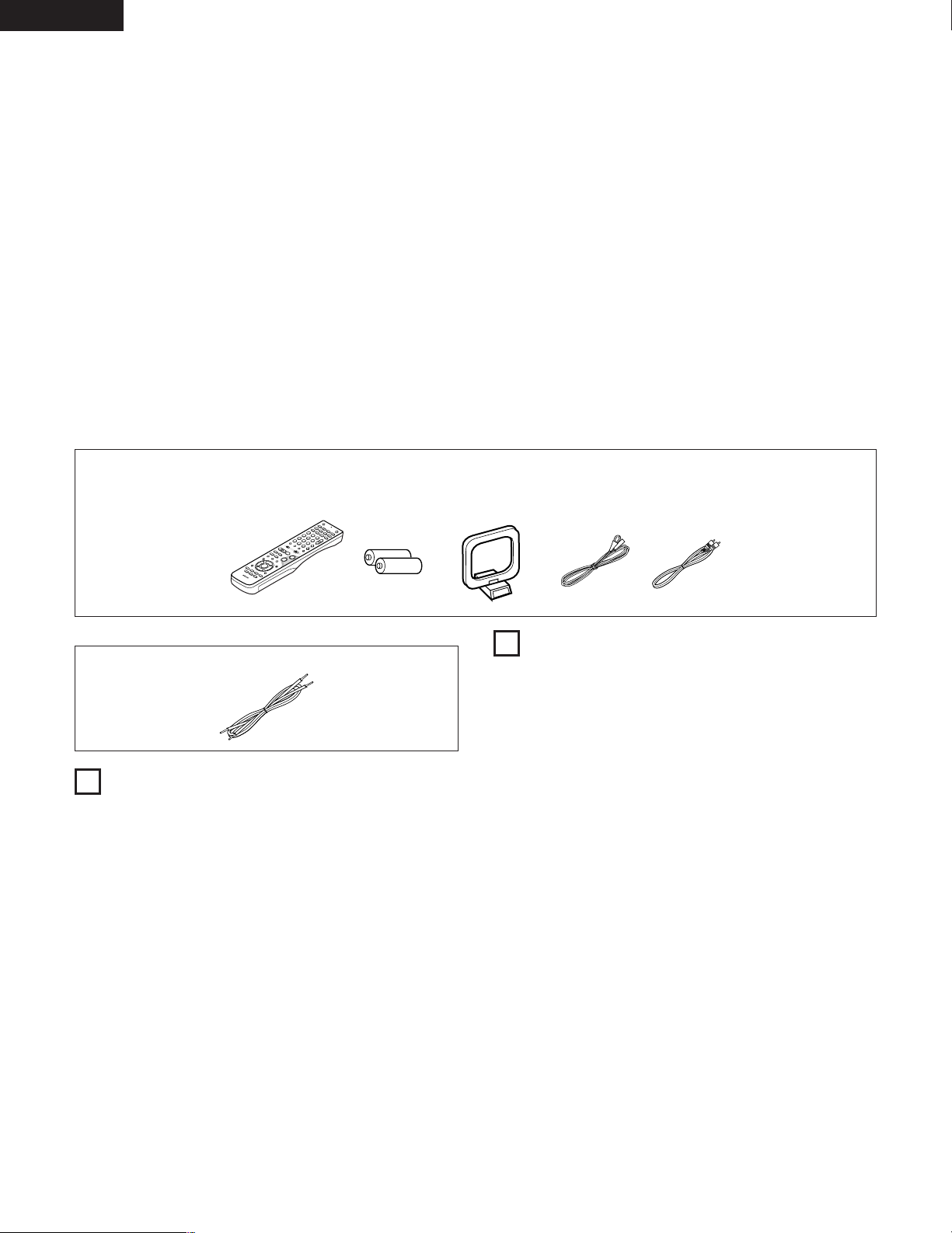
ACCESSORIES
2
ADV-M71
q Operating instructions .....1 w Warranty ( for North America model only )......................1 e Service station list...................1 r Remote control unit
t R6P/AA batteries .............2 y AM loop antenna ............1 u FM indoor antenna........1 i Video cord ...............................1 (RC-936)........................1
SC-U71 [D-M71DVS only]
q Connecting cable (Approx. 3 m) .............................................................. 2
1
BEFORE USING
Pay attention to the following before using this unit:
• Moving the set
To prevent short circuits or damaged wires in the connection cords,
always unplug the power cord and disconnect the connection cords
between all other audio components when moving the set.
• Before turning the power switch on
Check once again that all connections are proper and that there are
not problems with the connection cords. Always set the power
switch to the standby position before connecting and disconnecting
connection cords.
• Store this instructions in a safe place.
After reading, store this instructions along with the warranty in a
safe place.
• Note that the illustrations in this instructions may differ from
the actual set for explanation purposes.
Check that the following parts are included in addition to the main unit:
⁄3 DOLBY / DTS SURROUND.................................................................46~48
⁄4 SURROUND PLAYBACK.....................................................................49~61
⁄5 LISTENING TO THE RADIO................................................................62~64
⁄6 ON-SCREEN DISPLAY ..............................................................................65
⁄7 USING THE ON-SCREEN DISPLAY ....................................................66~83
⁄8 USING THE TIMER .............................................................................84~90
⁄9 CHANGING THE DEFAULT SETTINGS (DVD)...................................91~103
¤0 SYSTEM FUNCTION.......................................................................104~107
¤1 LAST FUNCTION MEMORY ...................................................................108
¤2 INITIALIZATION OF THE MICROPROCESSOR ......................................108
¤3 TROUBLESHOOTING .....................................................................109, 110
¤4 SPECIFICATIONS ....................................................................................111
2
CAUTIONS ON INSTALLATION
(1) DVD SURROUND RECEIVER UNIT
Noise or disturbance of the picture may be generated if this unit or
any other electronic equipment using microprocessors is used near a
tuner or TV.
If this happens, take the following steps:
• Install this unit as far as possible from the tuner or TV.
• Set the antenna wires from the tuner or TV away from this unit’s
power cord and input/output connection cords.
• Noise or disturbance tends to occur particularly when using indoor
antennas or 300 Ω/ohms feeder wires. We recommend using
outdoor antennas and 75 Ω/ohms coaxial cables.
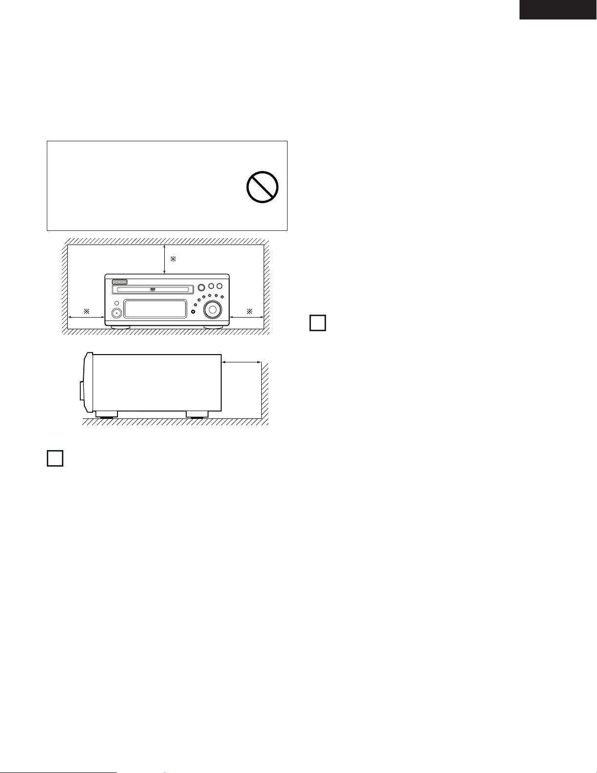
For heat dispersal, leave at least 10 cm/4 inch of space between
the top, back and sides of this unit and the wall or other
components.
(2) SPEAKER UNIT (D-M71DVS only)
The tone character produced by speaker systems depends on
such factors as the size and type of room, the method of
installation, etc. Pay attention to the following points when
installing the speaker systems.
• If the bass sound is overemphasized when the speaker systems
are installed directly on the floor, set them on concrete blocks or
other hard stands.
• Note that howling may be produced if the speaker systems are
placed on the same stand or shelf as a record player.
• If there are walls or glass doors behind or in front of the speaker
systems, use heavy curtains, etc., to prevent resonance and
reflection.
4
Page 5
ENGLISH
B
• This is an anti-magnet type speaker system which can be used near
television sets, etc., but with some TV sets the colors may become
blotchy. If this happens, turn off the TV’s power, wait 15 to 30
minutes, and turn the power back on. The TV’s self demagnetizing
circuit will improve the picture. If the colors are still blotchy, move
the speaker systems further away from the TV.
• Also note that if there is a magnet or any device generating
magnetic force nearby, interaction between this device and the
speaker systems can cause the colors on the TV to become
blotchy.
WARNING
• For your safety, do not put anything nor lean
yourself on the loudspeakers.
• Do not push the loudspeaker from aside to
protect it from topping that may cause serious
accident.
• Fix speaker cables to prevent being caught on it
and making loudspeakers topping down.
10 cm/4 inch or more
10 cm/4 inch or more
Wall
3
CAUTIONS ON HANDLING
(1) DVD SURROUND RECEIVER UNIT
• Switching the input function when input jacks are not
connected
A clicking noise may be produced if the input function is switched
when nothing is connected to the input jacks. If this happens, either
turn down the MASTER VOLUME control or connect components
to the input jacks.
• Muting of PRE OUT jacks, HEADPHONE jack and SPEAKER
terminals
The PRE OUT jacks, HEADPHONE jacks and SPEAKER terminals
include a muting circuit. Because of this, the output signals are
greatly reduced for several seconds after the power switch is
turned on or input function, surround mode or any other-set-up is
changed. If the volume is turned up during this time, the output will
be very high after the muting circuit stops functioning. Always wait
until the muting circuit turns off before adjusting the volume.
• Whenever the power switch is in the STANDBY state, the
apparatus is still connected on AC line voltage.
Please be sure to unplug the cord when you leave home for,
say, a vacation.
(2) SPEAKER UNIT [D-M71DVS only]
• Avoid placing the speaker systems in places exposed to direct
sunlight for long periods of time or near heaters or other heating
equipment.
• Placing in humid or dusty places may result in damage.
• Exposing the cabinet to insecticides or wiping it with benzene,
thinner or other solvents may result in damage or discoloration to
the finish. Use a soft cloth or silicone cloth to wipe any dirt off the
cabinet. Use cloths containing chemical substances with care.
• Do not apply inputs exceeding the speaker system’s max. input (the
input which can be applied a short period of time with regular
program sources).
• The output terminals may differ depending on the amplifier being
used. Consult the amplifier’s instructions.
• Clipping or other problems may occur in the output waveform when
using the speaker systems with a high output and the amplifier’s
tone controls set to the maximum. Avoid using them under these
conditions.
• Never play such special signals as a tape recorder’s fast-forwarding
signals or sine waves continuously.
• When moving the speaker systems, be careful not to apply excess
force to the speaker nets. Doing so could damage the speaker
units.
4
FEATURES
The ADV-M71 combines an AV amplifier and DVD player, the core
components of a home theater system, into a single compact,
stylish body. The system takes up little space, and the aluminum
front panel and half mirror of the display make for an elegant
design that blends in nicely with the décor in your room.
1. 2-channel power amplifier with Dolby Virtual Speaker
compatibility
The ADV-M71 is equipped with two 35W (6 Ω/ohms 1kHz, T.H.D.
10%) power amplifiers that make it compatible with new Dolby
Virtual Speaker technology for recreating a 5.1-channel
environment virtually using a 2-channel configuration. (Dolby
Virtual Speaker is an proprietary technology of Dolby Laboratories.)
A high performance digital signal processor enables playback of
Dolby Digital and DTS multi-channel surround signals in the Dolby
Virtual Speaker mode. Surround sound can be achieved with the
Dolby Virtual Speaker mode for CDs and other 2-channel sources
in combination with the Dolby Pro Logic
2. 3.1-channel pre-out terminals allowing expansion into a 5.1-
channel surround system
When used in combination with a commercially available
subwoofer with built-in amplifier and power amplifier, the ADVM71 can be expanded into a 5.1-channel surround system. The
ADV-M71 not only recreates an accurate sound field for multichannel sources, it is also compatible with wide mode playback in
the Dolby Virtual Speaker mode.
3. Dolby Pro Logic II decoder for expanding sound field playback
The ADV-M71 is equipped with a Dolby Pro Logic II decoder for
expanding sound field playback for Dolby Surround and stereo
music sources.
4. DENON’s unique sound field simulation using the DSP
The ADV-M71 is compatible with the Rock Arena, Jazz Club and
Video Game modes with a 2-channel configuration. In a 5.1channel configuration, it is also compatible with the 5-Channel
Stereo, Mono Movie and Matrix modes.
II decoder.
5
Page 6
ENGLISH
1
Recordable
ReWritable
5. High performance DVD drive for progressive image output
compatibility
The ADV-M71 is compatible with various functions offered by DVD
sources, including multiple audio (up to 8 languages), multiple
subtitle (up to 32 languages), multiple angle playback, viewing
restriction, etc.
6. Quick setup and on-screen display compatibility
DVDs can be enjoyed simply by selecting the TV and speaker
configuration to be used. Even with a 5.1-channel speaker
configuration, standard parameters can be set automatically simply
by selecting the size of the room in which the system is being
used and the listening position. The system can be set up using an
on-screen display function.
5
DISCS
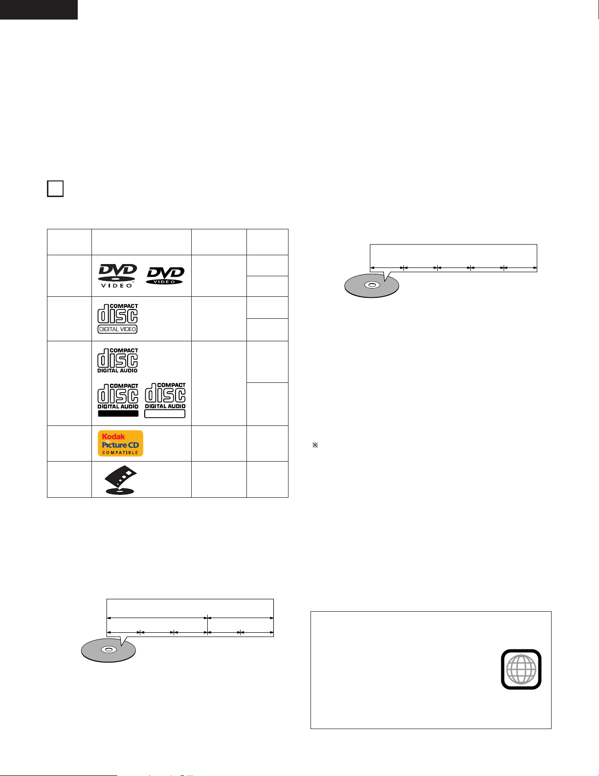
• The types of discs listed on the table below can be used on the ADV-M71.
The marks are indicated on the disc labels or jackets.
Usable
discs
DVD video
DVD audio
(NOTE 1)
Video CD
CD
CD-R
CD-RW
(NOTE 2)
Picture CD
FUJICOLOR
CD
Mark (logo)
Recorded
signals
Digital audio +
digital video
(MPEG2)
Digital audio +
digital video
(MPEG1)
Digital audio
MP3
WMA
Digital picture
(JPEG)
Digital picture
(JPEG)
Digital picture
(JPEG)
Disc size
12 cm
8 cm
12 cm
8 cm
12 cm
8 cm
12 cm
12 cm
7. Remote control unit with preset memory function
The ADV-M71 comes with a remote control unit equipped with a
preset memory function including the remote control operation
codes for D-M31 series cassette decks and DENON remote
control compatible components as well as the remote control
operation codes of other major brands of TVs and video decks.
8. Convenient system functions
When system connections are made with a D-M31 series cassette
deck, such system functions as auto function selection,
synchronized recording and timer recording/playback can be
performed easily.
For example:
Track 1 Track 2 Track 3 Track 4 Track 5
2 The following types of discs cannot be played on the ADV-
M71:
• DVDs with region numbers other than “1” or “ALL”
• DVD audio discs (NOTE 1)
• DVD+R/+RW
• DVD-ROM/RAMs
• CVD
• SVCD
• CD-ROMs (Only MP3/WMA file can be played)
• VSDs
• CDVs (Only the audio part can be played.)
• CD-Gs (Only the audio is output.)
• Photo CDs (NEVER play such discs on the ADV-M71)
If you attempt to play photo CDs, the data on the disc may be
damaged.
NOTE 1: Video part which based on DVD-video specification only can
be played.
NOTE 2: According to recording quality, some CD-R/RW cannot be
played.
2 Disc terminology
• Titles and chapters (DVD-videos)
DVD-videos are divided into several large sections called “titles”
and smaller sections called “chapters”.
Numbers are allotted to these sections. These numbers are
called “title numbers” and “chapter numbers”.
For example:
Chapter 1 Chapter 2 Chapter 3 Chapter 1 Chapter 2
• Tracks (video and music CDs)
Video and music CDs are divided into sections called “tracks”.
Numbers are allotted to these sections. These numbers are
called “track numbers”.
6
Title 1
• Playback control (video CDs)
Video CDs including the words “playback control” on the disc or
jacket are equipped with a function for displaying menus on the
TV screen for selecting the desired position, displaying
information, etc., in dialog fashion.
In this manual, playing video CDs using such menus is referred
to “menu playback”.
Video CDs with playback control can be used on the ADV-M71.
Title 2
NOTE:
• This DVD video player is designed and
manufactured to respond to the Region
Management Information that is recorded on
a DVD disc.
If the Region number described on the DVD
disc does not correspond to the Region
number of this DVD video player, this DVD
video player cannot play this disc.
The Region number for this DVD video player
is 1.
Page 7
6
CAUTIONS ON HANDLING DISCS
ENGLISH
Discs
Only the discs including the marks shown on page 6 can be played on
the ADV-M71.
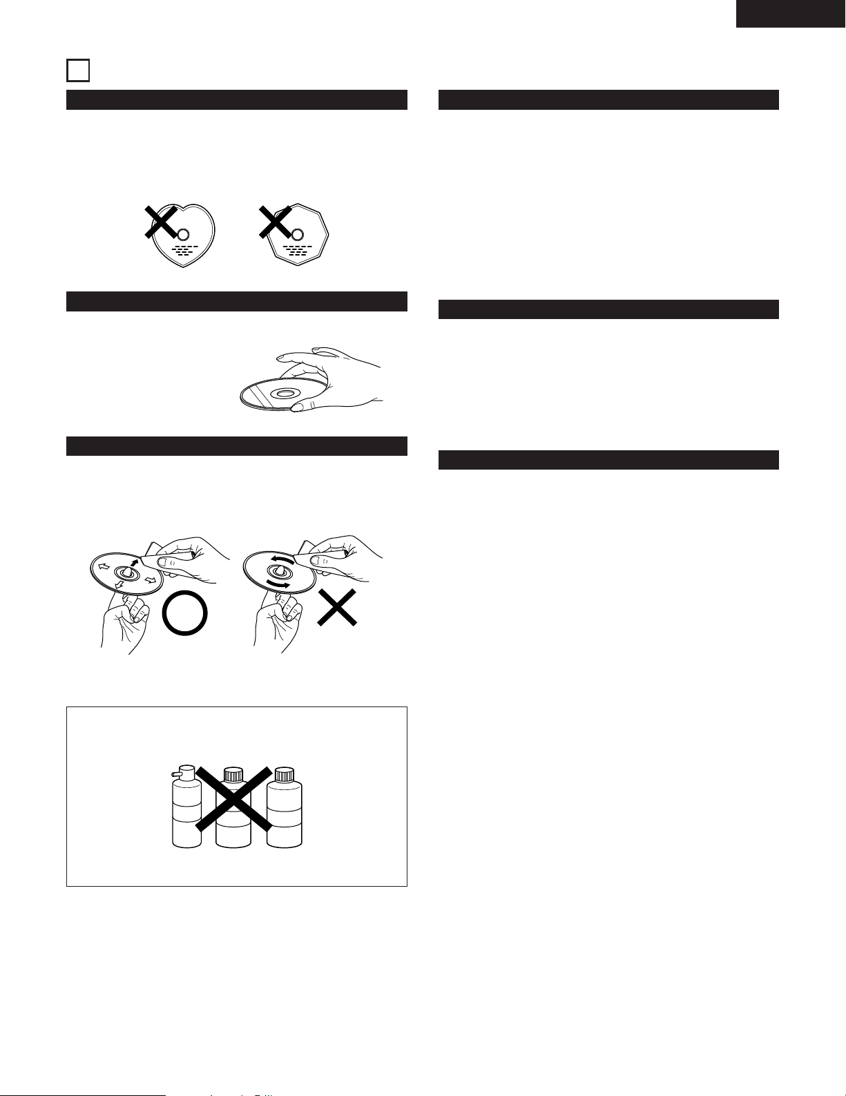
Note, however, that discs with special shapes (heart-shaped discs,
hexagonal discs, etc.) cannot be played on the ADV-M71. Do not
attempt to play such discs, as they may damage the player.
Holding Discs
Avoid touching the surface of discs when loading and unloading them.
Be careful not to get
fingerprints on the signal
surface (the side which
shines in rainbow colors).
Cleaning Discs
Fingerprints or dirt on the disc may lower sound and picture quality
2
or cause breaks in playback. Wipe off fingerprints or dirt.
Use a commercially available disc cleaning set or a soft cloth to
2
wipe off fingerprints or dirt.
Wipe gently from the middle
outwards.
Do not wipe with a circular
motion.
Cautions on Handling Discs
• Do not get fingerprints, grease or dirt on discs.
• Be especially careful not to scratch discs when removing them
from their cases.
• Do not bend discs.
• Do not heat discs.
• Do not enlarge the center hole.
• Do not write on the labeled (printed) side with a ball-point pen or a
pencil.
• Water droplets may form on the surface if the disc is moved
suddenly from a cold place to a warm one. Do not use a hairdryer,
etc., to dry the disc.
Cautions on Storing Discs
• Always eject discs after playing them.
• Keep discs in their cases to protect them from dust, scratches and
warping.
• Do not put discs in the following places:
1. Places exposed to direct sunlight for long periods of time
2. Humid or dusty places
3. Places exposed to heat from heaters, etc.
Cautions on Loading Discs
• Only load one disc at a time. Loading one disc on top of another
may result in damage or scratch the discs.
• Load 8 cm discs securely in the disc guide, without using an
adapter. If the disc is not properly loaded, it may slip out of the
guide and block the disc tray.
• Be careful not to let your fingers get caught when the disc tray is
closing.
• Do not place anything but discs in the disc tray.
• Do not load cracked or warped discs or discs that have been fixed
with adhesive, etc.
• Do not use discs on which the adhesive part of cellophane tape or
glue used to attach the label is exposed, or discs with traces of tape
or labels that have been peeled off. Such discs may get stuck inside
the player, resulting in damage.
NOTE:
• Do not use record spray or antistatic. Also do not use volatile
chemicals such as benzene or thinner.
Record
spray
Thinner Benzene
7
Page 8
ENGLISH
RLRLRLR
L
R
L
R
L
7
CONNECTIONS
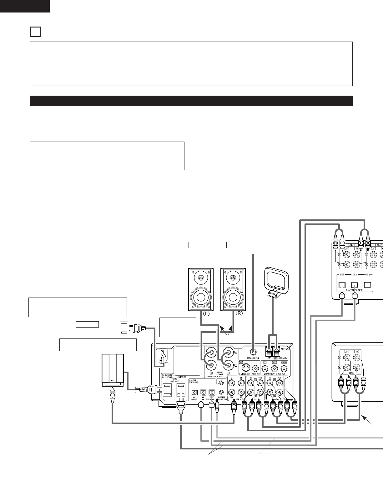
• Do not plug in the AC cord until all connections have been
completed.
• Be sure to connect the left and right channels properly (left with
left, right with right).
• Insert the plugs securely. Incomplete connections will result in the
generation of noise.
• Note that binding pin plug cords together with AC cords or placing
them near a power transformer will result in generating hum or
other noise.
• Noise or humming may be generated if a connected audio
equipment is used independently without turning the power of this
unit on. If this happens, turn on the power of the this unit.
(1) Connecting the audio components (D-M31 series)
• The ADV-M71 can be used connected in a system with the D-M31 series cassette deck (DRR-M31).
• For instructions on operating the separately sold cassette deck (DRR-M31), refer to their respective operating instructions.
• Only the DRR-M31 cassette deck can be connected directly to the ADV-M71 using system connections.
NOTE:
• This system includes digital circuitry which may cause interference such as
color blotching or changes in the color on TVs. If this happens, move the
system and the TV as far apart as possible.
Connecting the speaker systems
Connect the speaker system for the left channel (the left side as seen from the
front) to the L terminals, the speaker system for the right channel to the R
terminals. Refer to the instructions supplied with the speaker system for details.
Be sure to use speaker systems with an impedance of 6 Ω/ohms or greater.
Stereo audio cord
The ADV-M71 includes a built-in clock function,
so plug its power cord into a wall power outlet to
which electricity is supplied constantly.
AC CORD
AC 120 V, 60 Hz
Commercially available subwoofer
with built-in amplifier
ADV-M71 DVD
surround
receiver
Speaker system
SC-U71 [D-M71DVS only]
Or commercially available
speaker
Speaker cords
FM indoor antenna
(included)
AM loop antenna
(included)
Audio cord
Optical transmission
cables
System cords
Stereo audio cord
8
Page 9
ENGLISH
AC 120V 60Hz
UNSWITCHED
60W MAX
AC OUTLET
AC 120V 60Hz
UNSWITCHED
60W MAX
AC OUTLET
B
VIRTUAL SPEAKER
B
VIRTUAL SPEAKER
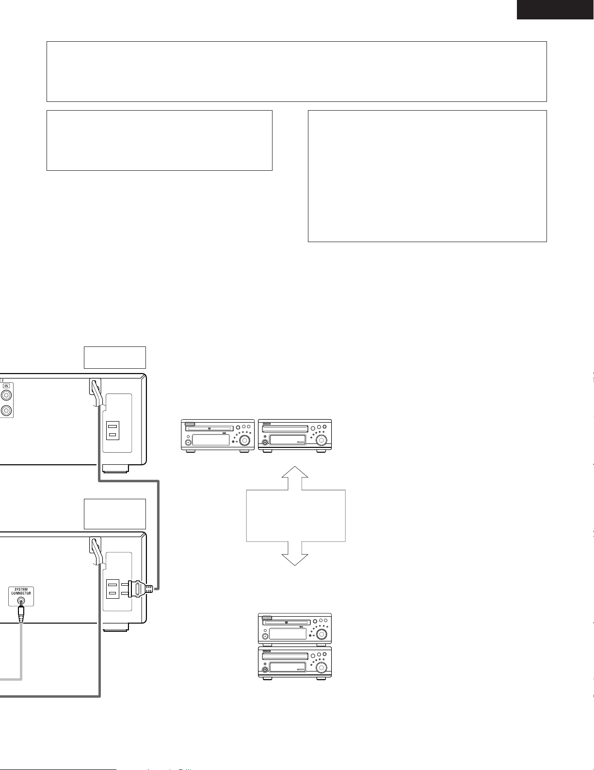
CAUTION:
• Only one cassette deck can be connected to the ADV-M71 using system connections. System operations cannot be performed properly if
two cassette decks are connected using system connections.
• Whenever the power operation switch is in the STANDBY position, the unit is still connected to AC line voltage.
• Please be sure to unplug the power cord when you leave home for, e.g.,a vacation, etc.
Note to CATV system installer:
This reminder is provided to call the CATV system installer’s attention to
Article 820-40 of the NEC which provides guidelines for proper
grounding and, in particular, specifies that the cable ground shall be
connected to the grounding system of the building, as close to the point
of cable entry as practical.
System operations
Such system operations as the timer and the auto power on functions, as well
as remote control operations cannot be performed unless all the RCA pin-plug
cords and system connector cords are connected between the units, so be sure
to make all the connections properly as shown in the diagram. Also,
disconnecting system connectors while the system is operating may result in
malfunctions. Be sure to unplug the power cord before changing connections.
MD recorder
(sold separately)
NOTES:
• Do not plug the power cord into the power outlet until all connections are
completed. Be sure to interconnect the channels (L to L (white) and R to R
(red)) properly, as shown on the diagram.
• Use the AC OUTLET for audio equipment only. Do not use them for hair
driers, etc.
• Insert the plugs securely. Incomplete connections may result in noise.
• Be sure to connect the speaker cords between the speaker terminals and
the speaker systems with the same polarities ( + to +, – to – ). If the
polarities are switched, the sound at the center will be weak, the position
of the different instruments will be unclear, and the stereo effect will be
lost.
• After unplugging the power cord, wait about 5 seconds before plugging it
back in.
• Note that setting the connection cords (pin-plug cords) next to the power
cords may result in humming or other noise.
Cassette deck
(DRR-M31)
(sold separately)
ADV-M71
DRR-M31
(Horizontal installation)
Install the sets as shown in one
of these diagrams. In either
case, be sure that the DVD
surround receiver’s ventilation
holes are not obstructed.
ADV-M71
DRR-M31
(Vertical installation)
9
Page 10
ENGLISH
L
R
AUDIO
OUT
L
R
LR
OUT IN
L
R
AUDIO
OUT
OPTICAL
B
R
L
L
R
L
R
L
R
L
R
R
L
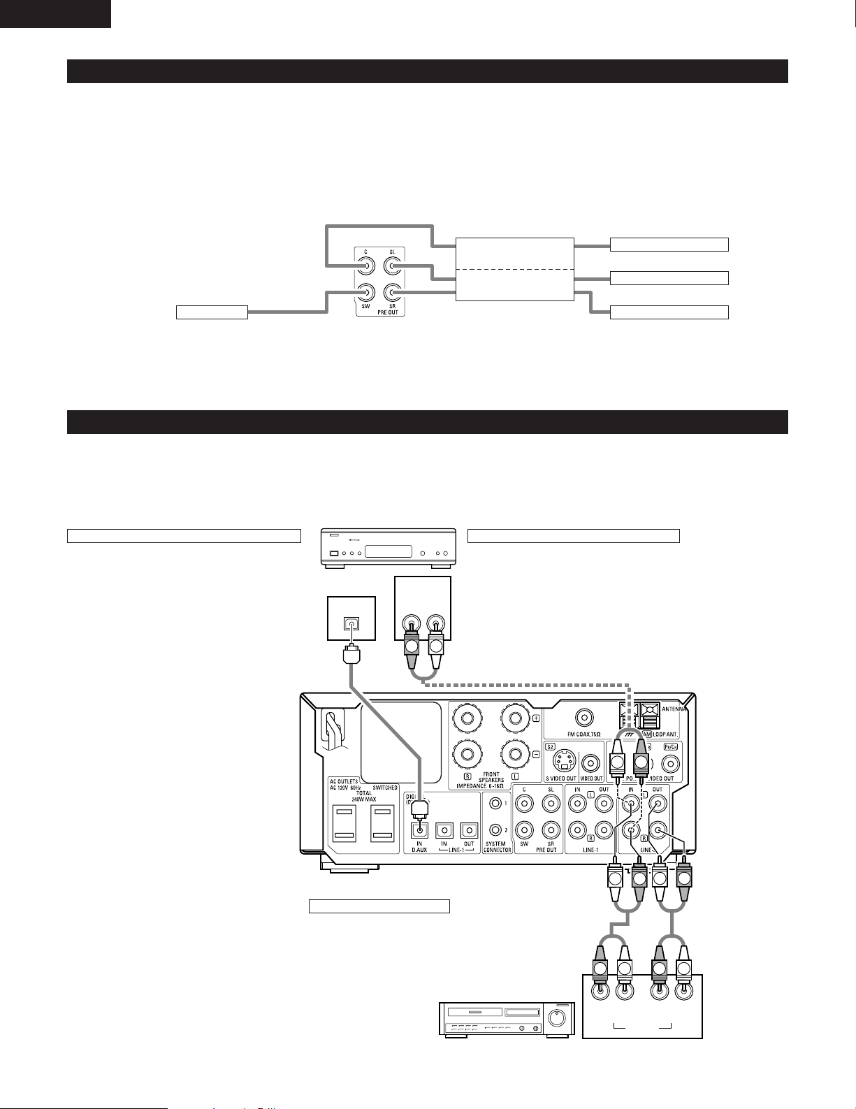
(2) Connecting the PRE OUT terminals (only with multi-channel settings)
• When used in combination with a commercially available subwoofer with built-in amplifier and power amplifier, the ADV-M71 can be expanded
into a 5.1-channel surround system.
• When making connections, also refer to the operating instructions of the other components.
• To make the 5.1-channel setting, set the speakers to “5.1 CH SURROUND” in the quick system setup and select “Room Setting” and
“Listening Position”. (See pages 31 to 32.)
IN
POWER AMPLIFIER
(for center ch)
IN
POWER AMPLIFIER
(for Surround ch)
SUBWOOFER
• Connect the subwoofer with built-in
amplifier.
IN
IN
• Connect the power
amplifier for center and
surround speaker
system.
(3) Connecting the Audio Signals of a Digital Satellite Tuner and VCR
• Connect the video signals directly to the TV and switch the picture on the TV.
• When making connections, also refer to the operating instructions of the other components.
Digital satellite/cable tuner
Connection to the optical digital input terminal
• Only audio signals are input to the optical digital input
terminal.
• Use a commercially available optical transmission
cable for connection to the optical transmission
terminal (OPTICAL).
Connection of a digital satellite/cable tuner
• For tuners equipped with an optical digital output terminal,
connect the digital output terminal to the DIGITAL D.AUX IN
terminal on the ADV-M71 using an optical transmission cable.
• To connect the audio output terminals, use whatever of the
ADV-M71’s LINE-1 or LINE-2 terminals are open.
Center Speaker
Surround (L) Speaker
Surround (R) Speaker
Connection of a video deck
• Connect the video deck’s audio output and audio input
terminals to whatever of the ADV-M71’s LINE-1 or LINE-2
terminals are open using pin-plug cords.
Video deck
10
Page 11
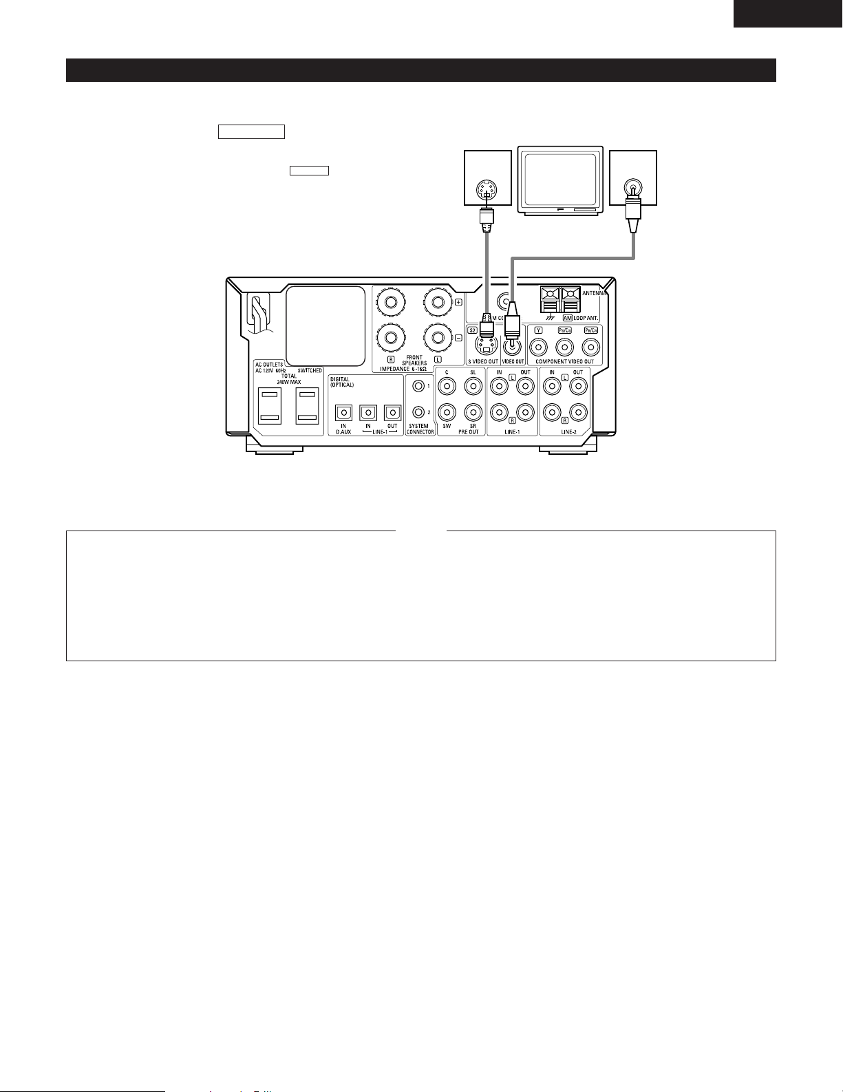
(4) Connecting a TV
S-VIDEO
IN
VIDEO
IN
• When making connections, also refer to the operating instructions of the TV.
ENGLISH
S VIDEO TV
S VEDEO OUT
• Connect the TV’s S video input (S-VIDEO
INPUT) to the OUT jack using a
S jack connection cord.
VIDEO OUT
• Connect the TV’s video input (VIDEO
INPUT) to the VIDEO jack using a video
connection cord.
S-VIDEO
Monitor TV
• Connect this unit video outputs to the TV either directly. Do
not connect it via a VCR (video cassette recorder). Some
discs contain copy prohibit signals. If such discs are played
via a VCR, the copy prohibit system may cause disturbance
in the picture.
NOTES:
• Set the “TV TYPE” in “VIDEO SETUP” in “DVD SETUP” to
comply with your TV’s video format. When the TV is NTSC
formated set to NTSC.
When “PROGRESSIVE” is set, no video signals are output from
•
the VIDEO OUT or S-VIDEO OUT terminals. Set “INTERLACED”
if you want to use the VIDEO OUT or S-VIDEO OUT signals.
(Refer to page 39)
11
Page 12
ENGLISH
1
4
2
3
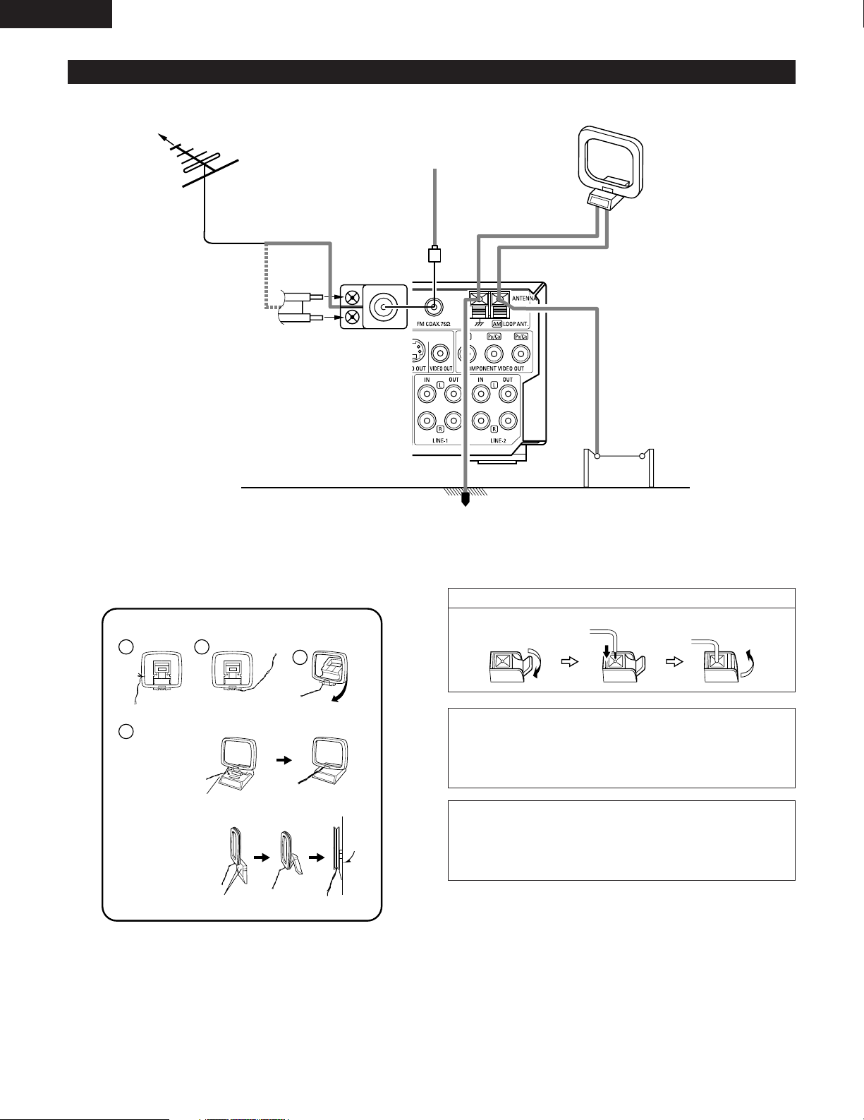
(5) Connecting the antenna terminals
DIRECTION OF
BROADCASTING
STATION
FM ANTENNA
75 Ω/ohms
COAXIAL
CABLE
FM INDOOR ANTENNA
(Supplied)
FM ANTENNA
ADAPTER
(Option)
GROUND
AM LOOP ANTENNA
(Supplied)
AM OUTDOOR
ANTENNA
• An F-type FM antenna cable plug can be connected directly.
• If the FM antenna cable’s plug is not of the F-type, connect using the F-type antenna adapter (Option).
AM loop antenna assembly
Connect to the AM
antenna terminals.
Remove the vinyl tie
and take out the
connection line.
a. With the antenna
on top any stable
surface.
Mount
b. With the antenna
attached to a wall.
Installation hole Mount on wall, etc.
Bend in the reverse
direction.
1. Push the lever. 2. Insert the conductor. 3. Return the lever.
Note to CATV system installer:
This reminder is provided to call the CATV system installer’s attention to
Article 820-40 of the NEC which provides guidelines for proper grounding
and, in particular, specifies that the cable ground shall be connected to the
grounding system of the building, as close to the point of cable entry as
practical.
NOTES:
• Do not connect two FM antennas simultaneously.
• Even if an external AM antenna is used, do not disconnect the AM loop
antenna.
• Make sure AM loop antenna lead terminals do not touch metal parts of the
panel.
Connection of AM antennas
12
Page 13
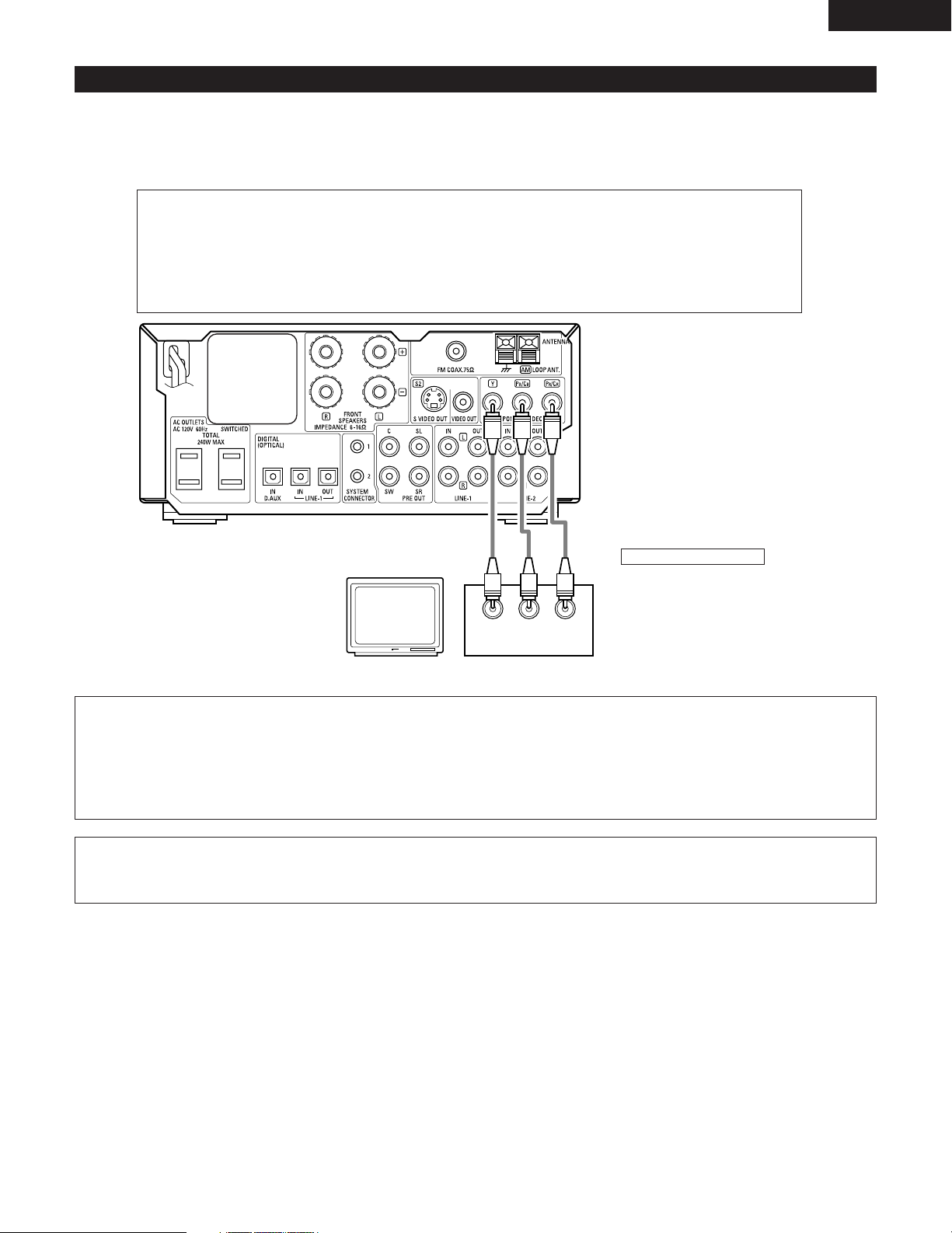
(6) Connecting to a TV or Monitor Equipped with Component Input Connectors.
• When making connections, also refer to the operating instructions of the other components.
• The video signals input to the VIDEO input (yellow) and S-Video input jacks are not output to the color difference (component) video jacks.
Color component output connectors (PR/CR, PB/CB and Y)
The red (P
reproduction of the colors.
• The color component input connectors may be marked differently on some TVs or monitors (P
Y, B-Y and Y/C
Connect in this way if your TV is compatible with Progressive Scan.
R/CR), blue (PB/CB) and brightness (Y) signals are output independently, achieving more faithful
R, PB and Y/R-
R, CB and Y, etc.). For details, refer to the TV’s operating instructions.
ENGLISH
Monitor TV
B/CB PR/CRY
P
COMPONENT VIDEO IN
Connecting a monitor TV
COMPONENT VIDEO OUT jack
• Connect the TV’s color difference
(component) video input jacks
(COMPONENT VIDEO INPUT) to the
COMPONENT VIDEO OUT jack using
75 Ω/ohms coaxial video pin-plug
cords.
NOTES:
• Use the three commercially available video cords to connect the ADV-M71’s color component output connectors to the TV or
monitor.
• Set the “TV TYPE” in “VIDEO SETUP” in “DVD SETUP” to comply with your TV’s video format. When the TV is NTSC formated
set to NTSC.
About selecting the video output “INTERLACED” or “PROGRESSIVE”, refer to page 39.
•
CONSUMERS SHOULD NOTE THAT NOT ALL HIGH DEFINITION TELEVISION SETS ARE FULLY COMPATIBLE WITH THIS
PRODUCT AND MAY CAUSE ARTIFACTS TO BE DISPLAYED IN THE PICTURE. IN CASE OF 525 PROGRESSIVE SCAN PICTURE
PROBLEMS, IT IS RECOMMENDED THAT THE USER SWITCH THE CONNECTION TO THE “STANDARD DEFINITION” OUTPUT.
13
Page 14
ENGLISH
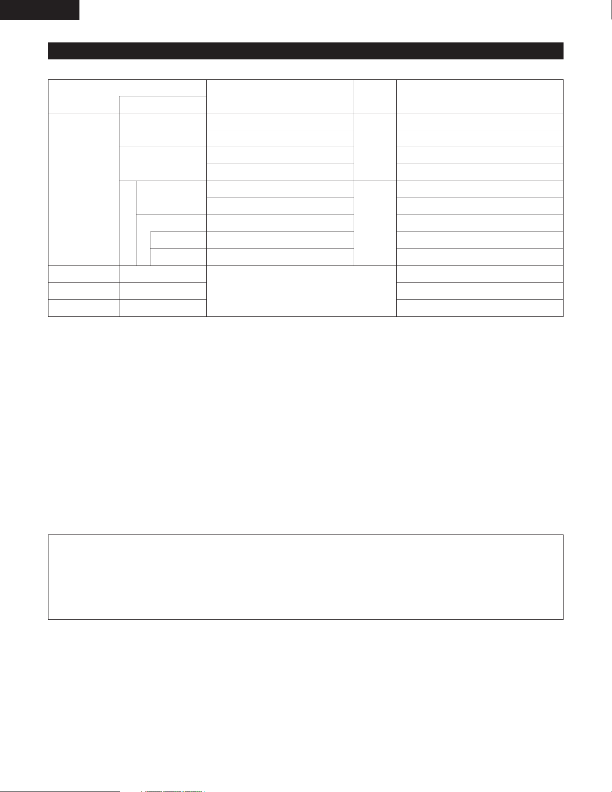
(7) Sound output from this unit digital and analog audio output connectors
2 When a disc is played on the ADV-M71 (DIGITAL OUT)
Refer to
page
98
98
Digital audio data output
Dolby Digital bitstream
2 channels PCM data (48 kHz/16bit)
DTS bitstream
2 channels PCM data (48 kHz/16bit)
48 kHz/16 ~24 bit PCM
48 kHz/16 bit PCM
48 kHz/16 bit PCM
48 kHz/16 bit PCM (when copy-protected)
96 kHz PCM (when not copy-protected)
44.1 kHz/16 bit PCM
44.1 kHz/16 bit PCM
32 ~ 48 kHz/16 bit PCM
DVD video
DVD audio
(video part only)
Video CD
Music CD
MP3/WMA CD
Audio recording format
Dolby Digital
DTS
48 kHz
96 kHz
Linear PCM
CP : ON
CP : OFF
MPEG 1
Linear PCM
MP3/WMA
Settings
Digital out : Normal
Digital out : PCM conversion
Digital out : Normal
Digital out : PCM conversion
LPCM conversion mode : OFF
LPCM conversion mode : ON
LPCM conversion mode : ON
LPCM conversion mode : OFF
LPCM conversion mode : OFF
• Linear PCM audio is the signal recording format used for music CDs.
While the signals are recorded at 44.1 kHz/16 bit for music CDs, for DVDs they are recorded at 48 kHz/16 bit to 96 kHz/24 bit, providing
higher sound quality than music CDs.
2 About the LINE-1 and LINE-2 analog recording outputs
When the DVD or the D.AUX digital input is selected:
• Dolby Digital, DTS, AAC and PCM digital signals are automatically converted to 2-channel stereo signals before being output (except
when in the Dolby Headphone mode) and can be recorded in analog. (For what happens in the Dolby Headphone mode, see 3 below.)
When TUNER, LINE-1 or LINE-2 is selected:
• The selected analog audio signals from the tuner or from the device connected to the LINE-1 or LINE-2 analog input terminals (IN) are
output unchanged, regardless of the ADV-M71’s input mode or surround mode. (The same is true for the device connected to the
D.AUX terminals when “LINE-2” under “⁄0 SETTING UP THE SYSTEM – (3) Detailed system setup – [5] Function settings” is set to
“D.AUX”.)
Recording output during playback of a DVD, D.AUX or LINE-1 digital input source in the Dolby Headphone mode:
• In the Dolby Headphone mode with a DVD or a digital input selected, the Dolby Headphone mode analog audio signals currently being
played are output and can be recorded in analog. (See pages 57 and 58.)
Cautions during analog recording of DVDs or digital input sources:
• Do not switch the ADV-M71’s input mode, surround mode or surround parameters during recording. Doing so will interrupt the
sound being recorded.
We recommend setting the surround mode to “STEREO” or “DIRECT”.
• When using headphones, recording is automatically performed in the Dolby Headphone mode. Do not disconnect the headphones
or switch the headphones mode during recording.
14
Page 15
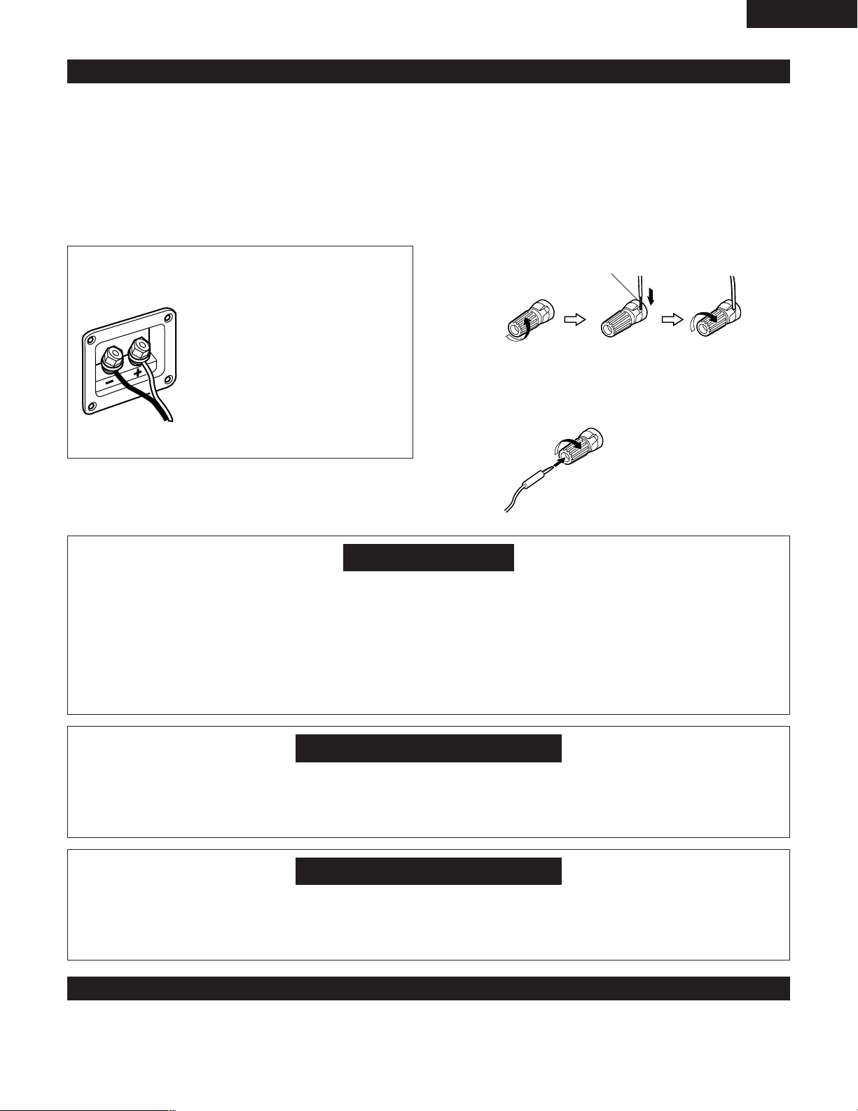
(8) Speaker system connections
Be sure to turn the amplifier’s power off when connecting the
speaker systems.
• Use the included cables to connect the input terminals on the back
of the speaker systems (see diagram) to the amplifier’s speaker
output terminals. Connect the speaker system for the left channel
amplifier’s “L” terminals, the one for the right channel to the
amplifier’s “R” terminals, matching the polarities (“≈” and “√”
marks). Inverting the polarities will result in unnatural sound, with
the phase off or no low bass sound. Also check that all two terminal
knobs are tightly fastened.
Connections
(The red terminals on the right side are the “≈” terminals, the black
ones on the left side the “√” terminals.)
Loosen the terminals knobs, insert the cables’
core wires, then tighten the knobs.
ENGLISH
Connecting the speaker cords
Use the included connection cords to connect the input terminals on
the backs of the speaker systems (see the diagram at the right) to the
ADV-M71’s speaker output terminals.
• Connect the speaker system for the left channel to the “L”
terminals, the speaker system for the right channel to the “R”
terminals, and be sure the polarities (“+” and “–”) are properly
interconnected.
• Note that if the polarities are inverted, the phase may be off and the
bass sound may be missing, resulting in an unnatural sound. Also
check that both the speaker terminal’s screws are tightly screwed.
Either twist the core wires
firmly or terminate the wires.
Connect to amplifier’s
“√” side. (Silver color)
Connect to amplifier’s “≈” side. (Copper color)
NOTE:
Make sure the core wires do not touch
each other.
qTurn the speaker
terminal
counterclockwis
e to loosen it.
Connecting banana plugs
wInsert the cord’s
core wires.
When using banana plugs, turn
clockwise to tighten the terminal
before inserting.
eTurn clockwise to
tighten the
terminal.
Protector circuit
• This unit is equipped with a high-speed protection circuit. The purpose of this circuit is to protect the speakers under circumstances such as
when the output of the power amplifier is inadvertently short-circuited and a large current flows, when the temperature surrounding the unit
becomes unusually high, or when the unit is used at high output over a long period which results in an extreme temperature rise.
When the protection circuit is activated, the speaker output is cut off and the power supply indicator LED flashes. Should this occur, please
follow these steps: be sure to switch off the power of this unit, check whether there are any faults with the wiring of the speaker cables or
input cables, and wait for the unit to cool down if it is very hot. Improve the ventilation condition around the unit and switch the power back
on.
If the protection circuit is activated again even though there are no problems with the wiring or the ventilation around the unit, switch off
the power and contact a DENON service center.
Note on speaker impedance
• The protector circuit may be activated if the set is played for long periods of time at high volumes when speakers with an impedance lower
than the specified impedance (for example speakers with an impedance of lower than 4 Ω/ohms) are connected. If the protector circuit is
activated, the speaker output is cut off. Turn off the set’s power, wait for the set to cool down, improve the ventilation around the set, then
turn the power back on.
Cautions on connecting
• With this unit’s speaker outputs, signals with the reverse phase of the “+” side output terminal’s signals are also output from the “-” side
output terminal.
Do not connect to a device for switching between multiple speakers (a speaker selector or audio channel selector) or connect in ways other
than described in this manual. Doing so will result in damage.
(8) Removing the speaker net (D-M71DVS only)
• The net on the front of the speaker system is detachable.
• To remove it, grasp it on both sides and pull it towards you.
• To attach the net, line up the plastic pieces holes out of the net with the sticking in the cabinet and press in.
15
Page 16
ENGLISH
B
BAND
PHONES
VOLUME
ON / STANDBY
DVD SURROUND RECEIVER ADV-M71
TONE/ SDB
FUNCTION
MENU/ SET
+
-
SURROUND/ SELECT
PUSH - PARAM.
VIRTUAL SPEAKER
!4 !3 !2 !1 !0 oi
uytrewq
8
PART NAMES AND FUNCTIONS
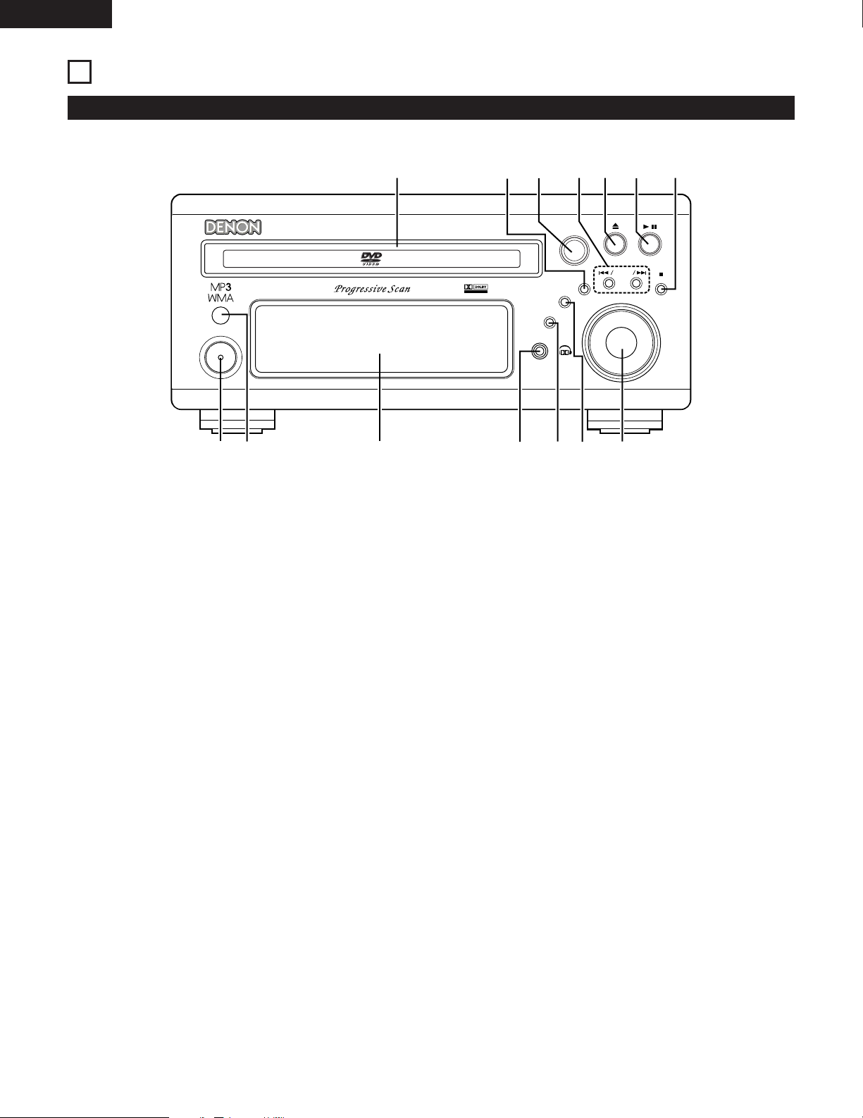
Front Panel
• For details on the functions of these parts, refer to the pages given in parentheses ( ).
Power button (ON/STANDBY)..................................................(30)
q
Remote control sensor.............................................................(21)
w
Display
e
Headphones jack (PHONES) ....................................................(57)
r
Function selector (FUNCTION).................................................(43)
t
Tone/super dynamic bass button (TONE/SDB) ........................(45)
y
Volume control (VOLUME).......................................................(41)
u
Stop/band button ( 2 BAND)..............................................(41, 62)
i
Play/pause button ( 1 / 3) .......................................................(40)
o
Open/close button ( 5 ) ..........................................................(40)
!0
Skip backward and forward buttons
!1
( 8 / – and + / 9 ) .....................................................(42, 62)
Surround/select knob (SURROUND/SELECT) ..........................(49)
!2
Surround parameter button (PARAMETER) .............................(50)
Menu/set button (MENU/SET) .................................................(64)
!3
Disc holder ...............................................................................(39)
!4
16
Page 17
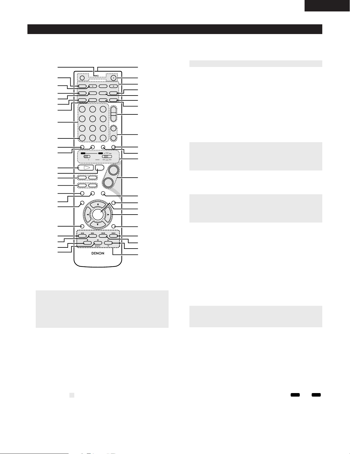
Remote control unit
+
-
+
-
RC-936
A / V
3
A-B REPEAT
SEARCH MODE
ONOFF
REPEAT RANDOM
CLEAR ZOOMSLIDE MODE
PROG/DIRECT
MEMO BANDMODE
STATU S
RETURN
ANGLE AUDIO
SUB TITLE
SETUP TONE/ SDB
FUNCTIONSURROUNDINPUT MODETEST TONE
DVD
TUNER
CH
3
-
+
21
654
987
0
/
10
CALL
ENTER
MUTING
+
10
DISPLAY MENU
TOP MENU
SYSTEM MD
CDR TAPE
TUNER TV / VCR
SURROUND
PARAMETER
CH SELECT
VCR
NTSC/PAL
SLEEP
ENTER
CD SRS
EDIT/MENUCHARAC.
REC
TIMETITLE
TUNING /
TV VOL
TV CH TV CH
TUNERDVD
MD/LINE-1
TAPE/LINE-2
AUTO DECODE
VIRTUALDIRECT
5CH STEREO
STEREO
D.AUX
-
+
VCR CH
IN/SURR.
IN/SURR.
DVD
T VTV INSOURCE
9
8
21
76
+
-
q
w
e
r
t
y
u
i
o
!0
!1
!2
!3
!4
!5
!6
!7
!8
!9
@0
@1
@2
@3
@4
@5
@6
@7
@8
@9
#0
#1
#2
#3
#4
#5
#6
#7
#9
#8
$0
$1
$2
$3
$4
$5
DVD
A / V
• For details on the functions of these parts, refer to the pages given in parentheses ( ).
• Some of the buttons on the remote control unit have some functions.
The functions are switched using the remote control mode selector switches.
Call button ................................................................................(70)
o
Test tone button.......................................................................(36)
!0
Input mode selector button......................................................(43)
!1
DVD play button .......................................................................(40)
!2
DVD stop button ......................................................................(41)
!3
DVD skip buttons .....................................................................(42)
!4
DVD search buttons...........................................................(42, 43)
!5
DVD pause button....................................................................(42)
!6
Status button............................................................................(44)
!7
Setup button.............................................................................(30)
!8
Channel select button ..............................................................(36)
!9
Return button ...........................................................................(41)
@0
Display button ..........................................................................(66)
@1
Angle button.............................................................................(80)
@2
Audio selector button...............................................................(78)
@3
Remote control signal transmission window...........................(21)
@4
Power button............................................................................(30)
@5
* System buttons...............................................................(19, 22)
@6
Zoom button.............................................................................(83)
@7
Slide mode button....................................................................(77)
@8
Search mode button.................................................................(42)
@9
Random button.........................................................................(71)
#0
Tuner tuning +/– buttons..........................................................(62)
#1
Tuner preset +/– buttons..........................................................(64)
#2
Function selector button ..........................................................(43)
#3
q
w
e
r
t
y
u
i
• For details on the function and operation of the various parts, refer to the pages indicated in (parentheses).
Transmission indicator
Sleep timer button ...................................................................(90)
NTSC/PAL button .....................................................................(11)
Clear button..............................................................................(70)
A-B repeat button.....................................................................(69)
Program/direct..........................................................................(70)
Repeat button...........................................................................(68)
Input source/surround mode selector button
* System buttons ............................................(19, 20, 22, 23, 28)
• Buttons indicated are DVD control buttons and can be operated when the remote control mode selector switch is set to the and
position.
• The functions of the system buttons (*) are switched using the remote control mode selector switch.
Surround mode selector button ...............................................(44)
#4
Mode selector switches.....................................................(18, 19)
#5
Main volume control buttons ...................................................(41)
#6
Muting button...........................................................................(45)
#7
Tone/SDB button ......................................................................(45)
#8
Enter button .............................................................................(29)
#9
Cursor button ...........................................................................(29)
$0
Surround parameter button......................................................(49)
$1
Top menu button......................................................................(81)
$2
Menu button.............................................................................(82)
$3
Subtitle button..........................................................................(79)
$4
* System buttons.........................................................(19, 22, 28)
$5
ENGLISH
17
Page 18
ENGLISH
DVD
A / V
+
-
+
-
RC-936
A / V
3
A-B REPEAT
SEARCH MODE
ONOFF
REPEAT RANDOM
CLEAR ZOOMSLIDE MODE
PROG/DIRECT
MEMO BANDMODE
STATUS
RETURN
ANGLE AUDIO
SUB TITLE
SETUP TONE/SDB
FUNCTIONSURROUNDINPUT MODETEST TONE
DVD
TUNER
CH
3
-
+
21
654
987
0
/
10
CALL
ENTER
MUTING
+
10
DISPLAY MENU
TOP MENU
SYSTEM MD
CDR TAPE
TUNER TV / VCR
SURROUND
PARAMETER
CH SELECT
VCR
NTSC/PAL
SLEEP
ENTER
CD SRS
EDIT/MENUCHARAC.
REC
TIMETITLE
TUNING /
TV VOL
TV CH TV CH
TUNERDVD
MD/LINE-1
TAPE/LINE-2
AUTO DECODE
VIRTUALDIRECT
5CH STEREO
STEREO
D.AUX
-
+
VCR CH
IN/SURR.
IN/SURR.
DVD
T VTV INSOURCE
9
8
21
76
+
-
3
12
q
w
e
3
q
q
A / V
SYSTEM
TUNER TV / VCR
IN/SURR.
DVD
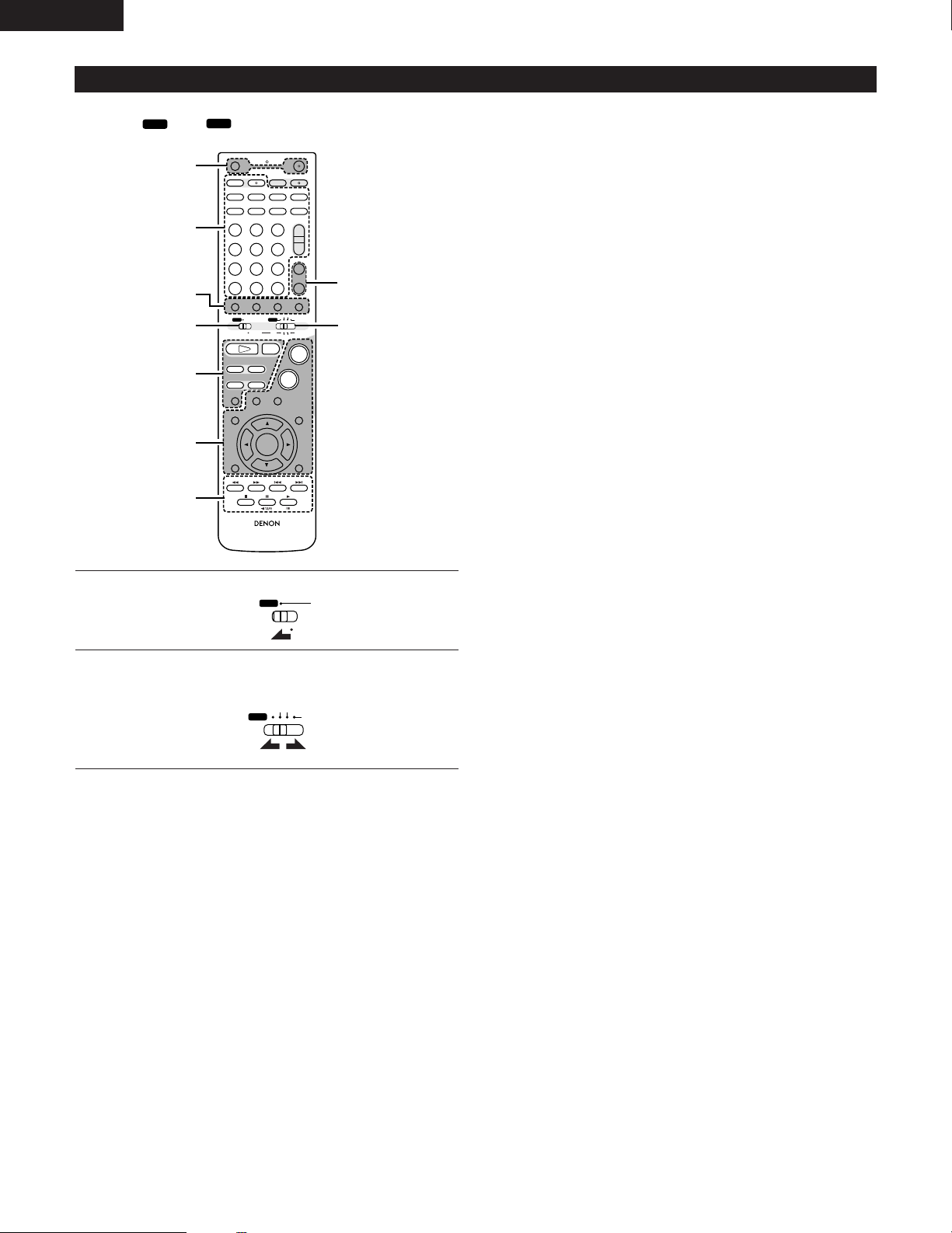
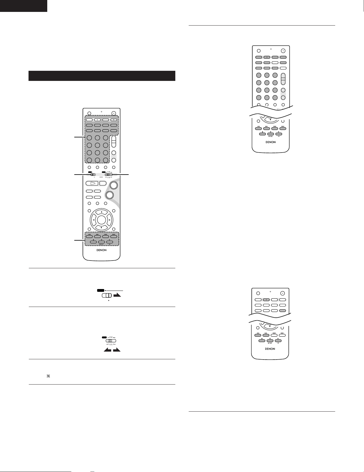
Names and functions of remote control unit buttons on the ADV-M71
• Buttons in sections q ~ e can be operated regardless of the position of mode switches 1 and 2.
• Consider and as standard positions, and switch as necessary to operate.
q Surround amplifier control buttons
FUNCTION : Function selection (in order)
SURROUND : Surround mode selection
INPUT MODE : Input mode selection
TEST TONE : Test tone on/off
MUTING : Muting on/off
STATUS : Status display selection
TONE/SDB : Tone/SDB selection and setting
SURROUND : Surround parameter selection and setting
PARAMETER
SET UP : Setup mode on/off
CH SELECT : Channel level selection and setting
•, ª, 0, 1 : Cursor up, down, left and right
ENTER : Enter setting
w DVD control buttons
8, 9 : Skip (cueing)
6, 7 : Search (fast-reverse and fast-forward)
ON : Turns the ADV-M71’s power on.
OFF : Turns the ADV-M71’s power off.
+ : Main volume up
– : Main volume down
1 : Play (auto power on and auto function selection)
2 : Stop
3 : Pause and frame-by-frame
Set mode switch 1 to the “A/V” position.
1
Set mode switch 2 to the position of the function you want to
operate (DVD, TUNER or IN/SURR).
2
e Tuner control buttons
CH +/– : Preset channel up/down
(auto power on and auto function selection)
18
Page 19
Operate the ADV-M71.
+
-
+
-
RC-936
A / V
3
A-B REPEAT
SEARCH MODE
ONOFF
REPEAT RANDOM
CLEAR ZOOMSLIDE MODE
PROG/DIRECT
MEMO BANDMODE
STATUS
RETURN
ANGLE AUDIO
SUB TITLE
SETUP TONE/SDB
FUNCTIONSURROUNDINPUT MODETEST TONE
DVD
TUNER
CH
3
-
+
21
654
987
0
/
10
CALL
ENTER
MUTING
+
10
DISPLAY MENU
TOP MENU
SYSTEM MD
CDR TAPE
TUNER TV / VCR
SURROUND
PARAMETER
CH SELECT
VCR
NTSC/PAL
SLEEP
ENTER
CD SRS
EDIT/MENUCHARAC.
REC
TIMETITLE
TUNING /
TV VOL
TV CH TV CH
TUNERDVD
MD/LINE-1
TAPE/LINE-2
AUTO DECODE
VIRTUALDIRECT
5CH STEREO
STEREO
D.AUX
-
+
VCR CH
IN/SURR.
IN/SURR.
DVD
T VT V INSOURCE
9
8
21
76
+
-
+
-
+
-
RC-936
A / V
3
A-B REPEAT
SEARCH MODE
ONOFF
REPEAT RANDOM
CLEAR ZOOMSLIDE MODE
PROG/DIRECT
MEMO BANDMODE
STATUS
RETURN
ANGLE AUDIO
SUB TITLE
SETUP TONE/SDB
FUNCTIONSURROUNDINPUT MODETEST TONE
DVD
TUNER
CH
3
-
+
21
654
987
0
/
10
CALL
ENTER
MUTING
+
10
DISPLAY MENU
TOP MENU
SYSTEM MD
CDR TAPE
TUNER TV / VCR
SURROUND
PARAMETER
CH SELECT
VCR
NTSC/PAL
SLEEP
ENTER
CD SRS
EDIT/MENUCHARAC.
REC
TIMETITLE
TUNING /
TV VOL
TV CH TV CH
TUNERDVD
MD/LINE-1
TAPE/LINE-2
AUTO DECODE
VIRTUALDIRECT
5CH STEREO
STEREO
D.AUX
-
+
VCR CH
IN/SURR.
IN/SURR.
DVD
T VT V INSOURCE
9
8
21
76
+
-
3
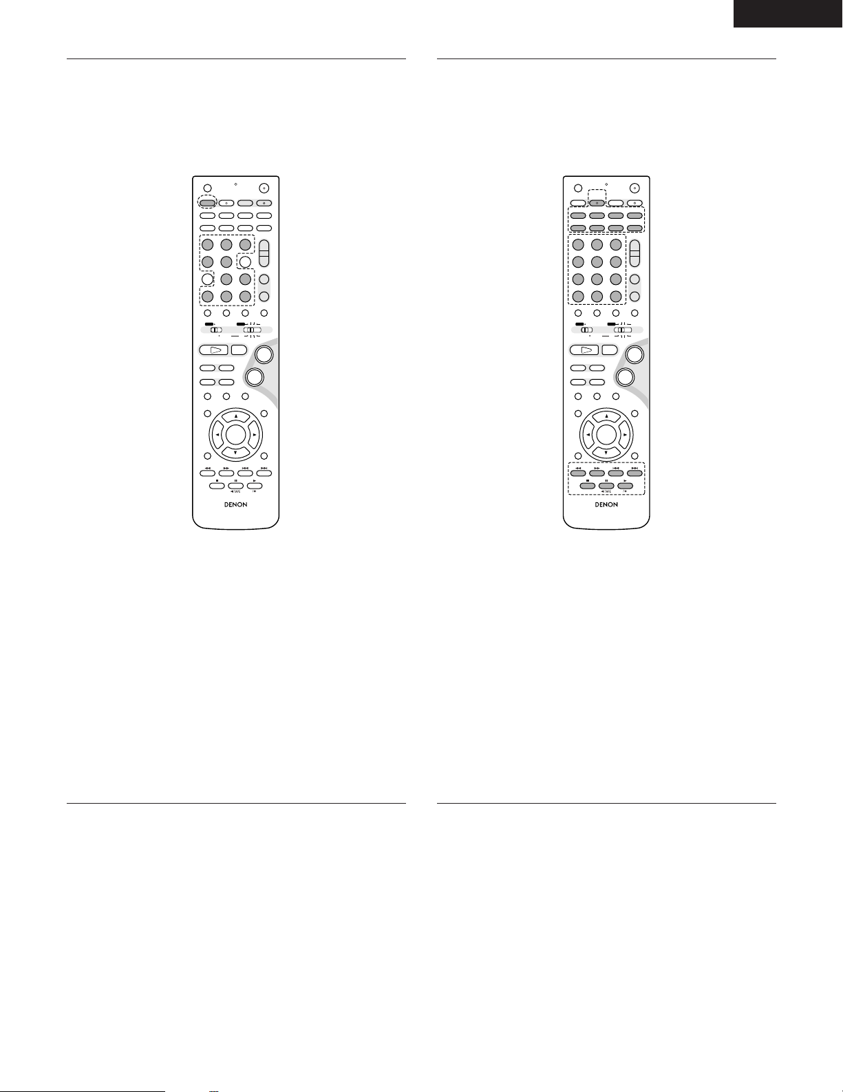
[1] Surround amplifier system buttons
(Operated with mode switch 2 set to “IN/SURR.”)
• These operations are possible with mode switch 1 at
any position.
The operations in gray print can be performed.
ENGLISH
[2] DVD system buttons
(Operated with mode switch 2 set to “DVD”)
SLEEP : Sleep on/off
DVD : Function DVD
TUNER : Function TUNER
D.AUX : Function D.AUX
MD/LINE-1 : Function MD/LINE-1
TAPE/LINE-2 : Function TAPE/LINE-2
5CH STEREO : 5-channel stereo surround mode
(when “5.1CH” selected in setup)
AUTO DECODE
: 2-channel mode switching when auto
decode surround mode set
(when “5.1CH” selected in setup)
VIRTUAL : 2-channel mode switching when Dolby
Virtual Speaker or Dolby VS surround mode
set
STEREO : Stereo mode
DIRECT : Direct mode
NTSC/PAL : NTSC/PAL selection
ZOOM : Zoom on/off
SLIDE MODE : JPEG image slide mode selection
A-B REPEAT : A-B repeat playback setting
CLEAR : Program clear
SEARCH MODE
: Title and chapter search selection
RANDOM : Random play on/off
REPEAT : Repeat play setting
PROG/DIRECT : Program/direct play selection
CALL : Program call
0 ~ 9, +10 : Number buttons
TOP MENU : Top menu call
MENU : Menu call
DISPLAY : Display call/selection
RETURN : Menu return
SUBTITLE : Subtitle language selection
AUDIO : Audio language selection
ANGLE : Angle selection
19
Page 20
ENGLISH
+
-
+
-
RC-936
A / V
3
A-B REPEAT
SEARCH MODE
ONOFF
REPEAT RANDOM
CLEAR ZOOMSLIDE MODE
PROG/DIRECT
MEMO BANDMODE
STATUS
RETURN
ANGLE AUDIO
SUB TITLE
SETUP TONE/SDB
FUNCTIONSURROUNDINPUT MODETEST TONE
DVD
TUNER
CH
3
-
+
21
654
987
0
/
10
CALL
ENTER
MUTING
+
10
DISPLAY MENU
TOP MENU
SYSTEM MD
CDR TAPE
TUNER TV / VCR
SURROUND
PARAMETER
CH SELECT
VCR
NTSC/PAL
SLEEP
ENTER
CD SRS
EDIT/MENUCHARAC.
REC
TIMETITLE
TUNING /
TV VOL
TV CH TV CH
TUNERDVD
MD/LINE-1
TAPE/LINE-2
AUTO DECODE
VIRTUALDIRECT
5CH STEREO
STEREO
D.AUX
-
+
VCR CH
IN/SURR.
IN/SURR.
DVD
T VT V INSOURCE
9
8
21
76
+
-
3
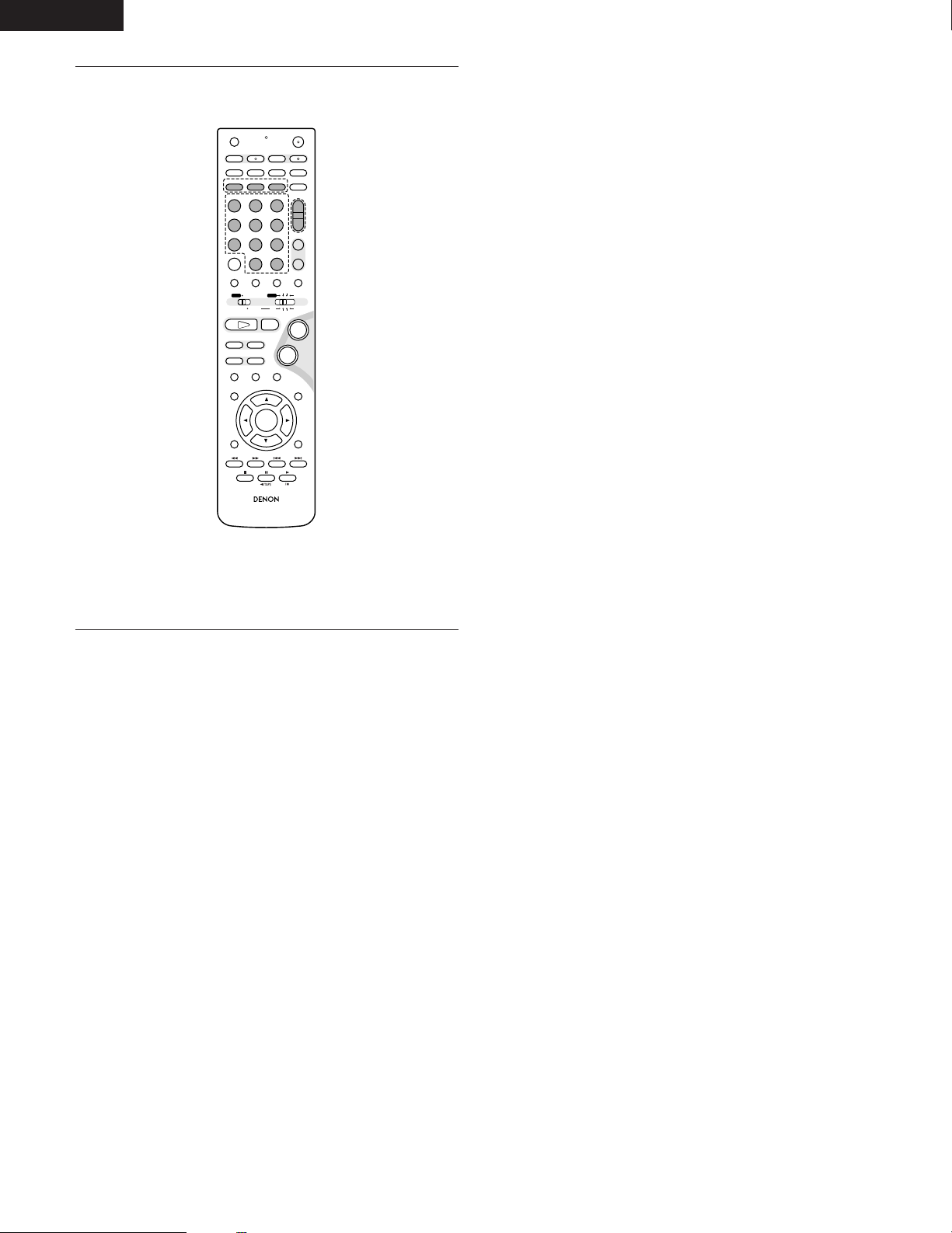
[3] Tuner system buttons
(Operated with mode switch 2 set to “TUNER”)
BAND : FM/AM band selection
MEMO : Preset memory
MODE : FM auto/mono mode selection
TUNER +/– : Tuning up/down
1 ~ 10, +10 : Preset channel number buttons
20
Page 21
ENGLISH
B
+
-
+
-
R
C
9
3
6
A
/
V
3
A
B
R
E
P
E
A
T
S
E
A
R
C
H
M
O
D
E
O
N
O
F
F
R
E
P
E
A
T
R
A
N
D
O
M
C
L
E
A
R
Z
O
O
M
S
LID
E
M
O
D
E
P
R
O
G
/
D
IR
E
C
T
M
EM
O
B
A
N
D
M
O
D
E
S
T
A
T
U
S
R
E
T
U
R
N
A
N
G
L
E
A
U
D
I
O
S
U
B
T
I
T
L
E
S
E
T
U
P
T
O
N
E
/S
D
B
F
U
N
C
T
I
O
N
S
U
R
R
O
U
N
D
I
N
P
U
T
M
O
D
E
T
E
S
T
T
O
N
E
D
V
D
T
U
N
E
R
C
H
3
-
+
2
1
6
5
4
9
8
7
0
/
1
0
C
A
L
L
EN
T
E
R
M
U
T
IN
G
+
1
0
D
IS
P
L
A
Y
M
E
N
U
TOP
M
E
N
U
S
Y
S
T
E
M
M
D
C
D
R
T
A
P
E
T
U
N
E
R
T
V
/ V
C
R
S
U
R
R
O
U
N
D
P
A
R
A
M
E
T
E
R
C
H
S
E
L
E
C
T
V
C
R
N
T
S
C
/
P
A
L
S
L
E
E
P
E
N
T
E
R
C
D
S
R
S
E
D
I
T
/
M
E
N
U
C
H
A
R
A
C
.
R
E
C
T
IM
E
T
I
T
L
E
T
U
N
I
N
G
/
T
V
V
O
L
T
V
C
H
T
V
C
H
T
U
N
E
R
D
V
D
M
D
/
L
IN
E
1
T
A
P
E
/L
I
N
E
2
A
U
T
O
D
E
C
O
D
E
V
IR
T
U
A
L
D
I
R
E
C
T
5
C
H
S
T
E
R
E
O
S
T
E
R
E
O
D
.A
U
X
-
+
V
C
R
C
H
IN
/
S
U
R
R
.
I
N
/
S
U
R
R
.
D
V
D
T
VTV
I
N
S
O
U
R
C
E
+
-
9
8
21
7
6
9
REMOTE CONTROL UNIT
• The included remote control unit (RC-936) can be used to operate not only this unit but other remote control compatible DENON components
as well. In addition, the memory contains the control signals for other remote control units, so it can be used to operate non-DENON remote
control compatible products.
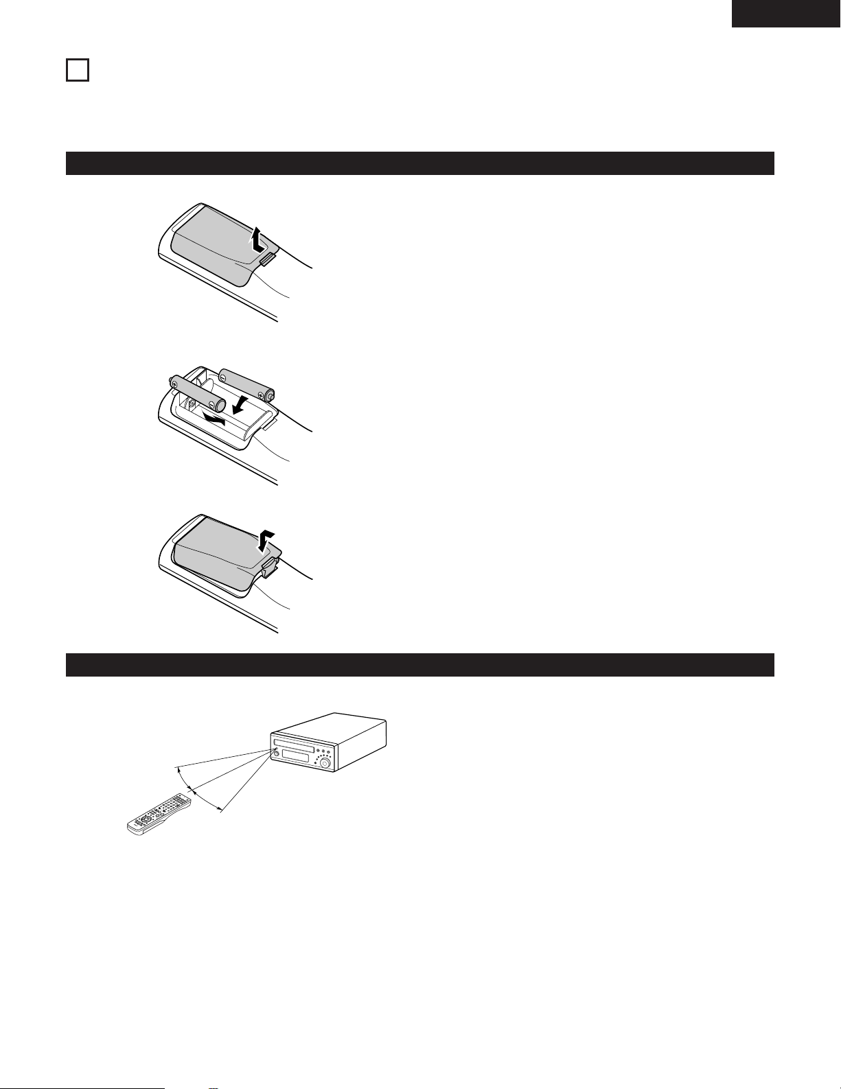
(1) Inserting the batteries
q Remove the remote control unit’s rear cover.
w Set three R6P/AA batteries in the battery compartment in the
indicated direction.
Notes on Batteries
• Use R6P/AA batteries in the remote control unit.
• The batteries should be replaced with new ones approximately
once a year, though this depends on the frequency of usage.
• Even if less than a year has passed, replace the batteries with new
ones if the set does not operate even when the remote control unit
is operated nearby the set. (The included battery is only for verifying
operation. Replace it with a new battery as soon as possible.)
• When inserting the batteries, be sure to do so in the proper
direction, following the “≈” and “√” marks in the battery
compartment.
• To prevent damage or leakage of battery fluid:
• Do not use a new battery together with an old one.
• Do not use two different types of batteries.
• Do not short-circuit, disassemble, heat or dispose of batteries in
flames.
• Remove the batteries from the remote control unit when you do
not plan to use it for an extended period of time.
• If the battery fluid should leak, carefully wipe the fluid off the inside
of the battery compartment and insert new batteries.
• When replacing the batteries, have the new batteries ready and
insert them as quickly as possible.
e Put the rear cover back on.
(2) Using the remote control unit
Approx. 7m / 22 feet
30°
30°
• Point the remote control unit at the remote sensor on the main unit
as shown on the diagram.
• The remote control unit can be used from a straight distance of
approximately 7 meters/22 feet from the main unit, but this
distance will be shorter if there are obstacles in the way or if the
remote control unit is not pointed directly at the remote sensor.
• The remote control unit can be operated at a horizontal angle of up
to 30 degrees with respect to the remote sensor.
NOTES:
• It may be difficult to operate the remote control unit if the remote
sensor is exposed to direct sunlight or strong artificial light.
• Do not press buttons on the main unit and remote control unit
simultaneously. Doing so may result in malfunction.
• Neon signs or other devices emitting pulse-type noise nearby may
result in malfunction, so keep the set as far away from such
devices as possible.
21
Page 22
ENGLISH
+
-
+
-
RC-936
A / V
3
A-B REPEAT
SEARCH MODE
ONOFF
REPEAT RANDOM
CLEAR ZOOMSLIDE MODE
PROG/DIRECT
MEMO BANDMODE
STATUS
RETURN
ANGLE AUDIO
SUB TITLE
SETUP TONE/SDB
FUNCTIONSURROUNDINPUT MODETEST TONE
DVD
TUNER
CH
3
-
+
21
654
987
0
/
10
CALL
ENTER
MUTING
+
10
DISPLAY MENU
TOP MENU
SYSTEM MD
CDR TAPE
TUNER TV / VCR
SURROUND
PARAMETER
CH SELECT
VCR
NTSC/PAL
SLEEP
ENTER
CD SRS
EDIT/MENUCHARAC.
REC
TIMETITLE
TUNING /
TV VOL
TV CH TV CH
TUNERDVD
MD/LINE-1
TAPE/LINE-2
AUTO DECODE
VIRTUALDIRECT
5CH STEREO
STEREO
D.AUX
-
+
VCR CH
IN/SURR.
IN/SURR.
DVD
T VT V INSOURCE
9
8
21
76
+
-
3
12
3
A / V
SYSTEM
MD
CDR TAPE
TUNER TV / VCR
IN/SURR.
IN/SURR.
DVD
+
-
+
-
A-B REPEAT
SEARCH MODE
ONOFF
REPEAT RANDOM
CLEAR ZOOMSLIDE MODE
PROG/DIRECT
MEMO BANDMODE
FUNCTIONSURROUNDINPUT MODETEST TONE
TUNER
CH
3
-
+
21
654
987
0
/
10
CALL
+
10
TUNER TV / VCR
VCR
NTSC/PAL
SLEEP
ENTER
CD SRS
EDIT/MENUCHARAC.
REC
TIMETITLE
TUNING /
TV VOL
TV CH TV CH
TUNERDVD
MD/LINE-1
TAPE/LINE-2
AUTO DECODE
VIRTUALDIRECT
5CH STEREO
STEREO
D.AUX
T VT V INSOURCE
A-B REPEAT
SEARCH MODE
ONOFF
REPEAT RANDOM
CLEAR ZOOMSLIDE MODE
PROG/DIRECT
MEMO BANDMODE
-
+
VCR
NTSC/PAL
SLEEP
ENTER
CD SRS
EDIT/MENUCHARAC.
REC
TIMETITLE
TUNING /
TV VOL
TV CH TV CH
TUNERDVD D.AUX
T VT V INSOURCE
RC-936
RETURN
ANGLE AUDIO
SUB TITLE
DISPLAY MENU
TOP MENU
SURROUND
PARAMETER
CH SELECT
-
+
VCR CH
RC-936
RETURN
ANGLE AUDIO
SUB TITLE
DISPLAY MENU
TOP MENU
SURROUND
PARAMETER
CH SELECT
-
+
VCR CH
• The included remote control unit (RC-936) can be used to operate
not only the ADV-M71 but also to perform system operations for
the D-M31 series and to operate other remote control compatible
DENON products. In addition, the remote control operation codes
of other major brands of TVs and video decks are also stored in the
remote control unit, so the unit can be used to operate these TVs
and video decks as well.
(3) Operating DENON audio components
• Turn on the power of all the components before operating them.
• Depending on the model and year of make of your component,
some of the keys may not work.
Set mode switch 1 to the “SYSTEM” position.
(Blue print)
1
[1] CD recorder system buttons
3
(operated with mode switch 2 set to “CDR”)
TIME : Disc time display
TITLE : Name display and selection of characters when
REC : Recording
SOURCE : CD recorder power on/off
EDIT/MENU : Menu selection
ENTER : Entering of menu items
CLEAR : Program clearing
RANDOM : Random play on/off
REPEAT : Repeat play setting
PROG/DIRECT : Program/direct playback selection
CALL : Program calling
1~10, +10 : Track number selection
8, 9 : Auto search (cueing)
6, 7 : Manual search (fast-reverse and fast-forward)
1 (/ 3) : Play (play/pause, auto power on and auto function
3 : Pause
2 : Stop
[2] Tape deck system button
(operated with mode switch 2 set to “TAPE”)
inputting names
selection with the CDR-M30)
22
Set mode switch 2 to the position for the component to be
operated (MD, CDR or TAPE).
2
(Blue print)
Operate the audio component.
• For details, refer to the component’s operating instructions.
3
Operation may not be possible for some models.
REC : Recording
CD SRS : CD synchronized recording (DRR-M31 system
function)
6, 7 : Rewind and fast-forward
1 : Forward direction play
0 TAPE : Reverse direction play (0 and 1: auto power on
and auto function selection with the DRR-M31)
Page 23
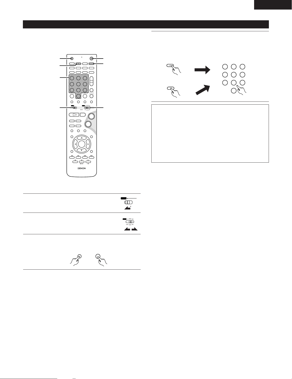
(4) TV and video deck preset memories
+
-
+
-
RC-936
A / V
3
A-B REPEAT
SEARCH MODE
ONOFF
REPEAT RANDOM
CLEAR ZOOMSLIDE MODE
PROG/DIRECT
MEMO BANDMODE
STATUS
RETURN
ANGLE AUDIO
SUB TITLE
SETUP TONE/SDB
FUNCTIONSURROUNDINPUT MODETEST TONE
DVD
TUNER
CH
3
-
+
21
654
987
0
/
10
CALL
ENTER
MUTING
+
10
DISPLAY MENU
TOP MENU
SYSTEM MD
CDR TAPE
TUNER TV / VCR
SURROUND
PARAMETER
CH SELECT
VCR
NTSC/PAL
SLEEP
ENTER
CD SRS
EDIT/MENUCHARAC.
REC
TIMETITLE
TUNING /
TV VOL
TV CH TV CH
TUNERDVD
MD/LINE-1
TAPE/LINE-2
AUTO DECODE
VIRTUALDIRECT
5CH STEREO
STEREO
D.AUX
-
+
VCR CH
IN/SURR.
IN/SURR.
DVD
T VT V INSOURCE
9
8
21
76
+
-
4
3
3
4
4
12
A / V
SYSTEM
MD
CDR TAPE
TUNER TV / VCR
IN/SURR.
IN/SURR.
DVD
OFF ON
TIME
T V
VCR
NTSC/PAL
REC
321
654
987
0
/
10
TUNERDVD
MD/LINE-1
TAPE/LINE-2
AUTO DECODE5CH STEREO
STEREO
D.AUX
• Components of other brands can be operated with the included
remote control unit by storing their codes in the preset memory.
Note that depending on the model some operations may not be
possible and some buttons may not operate properly.
Press the TV button to preset a TV, the VCR button to preset
a video deck, then input the 3-digit number corresponding to
4
the brand of the component whose signals are to be stored in
the preset memory (refer to the tables of remote control
codes on pages 24 to 27).
NOTES:
• When buttons are pressed while setting the preset memory,
their signals are sent from the remote control transmitter, so
cover the remote control sensor when setting the preset
memory to prevent accidental operation.
• Depending on the model and year of make, some of the remote
control codes for the brands included on the tables may not
operate properly.
• For some brands there are multiple types of remote control
codes. If an operation does not work, try changing to one of the
other codes.
ENGLISH
2 Not set upon shipment from the factory.
Set mode switch 1 to the “A/V” position.
1
Set mode switch 2 to the “TV/VCR” position.
2
Press the power ON button and the OFF button
simultaneously.
3
• The transmission LED (indicator) flashes.
23
Page 24
ENGLISH
Combinations of preset codes for different brands
TV
Admiral 045, 121
Adventura 122
Aiko 054
Akai 016, 027, 046
Alleron 062
A-Mark 007
Amtron 061
Anam 006, 007, 036
Anam National 061, 147
AOC 003, 007, 033, 038, 039, 047, 048, 049, 133
Archer 007
Audiovox 007, 061
Bauer 155
Belcor 047
Bell & Howell 045, 118
Bradford 061
Brockwood 003, 047
Candle 003, 030, 031, 032, 038, 047, 049, 050, 122
Capehart 003
Celebrity 046
Circuit City 003
Citizen 029, 030, 031, 032, 034, 038, 047, 049, 050, 054,
061, 095, 122, 123
Concerto 031, 047, 049
Colortyme 003, 047, 049, 135
Contec 013, 051, 052, 061
Cony 051, 052, 061
Craig 004, 061
Crown 029
Curtis Mathes 029, 034, 038, 044, 047, 049, 053, 095, 118
Daewoo 027, 029, 039, 048, 049, 054, 055, 106, 107, 137
Daytron 003, 049
Dimensia 044
Dixi 007, 015, 027
Electroband 046
Electrohome 029, 056, 057, 058, 147
Elta 027
Emerson 029, 051, 059, 060, 061, 062, 118, 123, 124, 139, 148
Envision 038
Etron 027
Fisher 014, 021, 063, 064, 065, 118
Formenti 155
Fortress 012
Fujitsu 004, 062
Funai 004, 062
Futuretech 004
GE 020, 036, 037, 040, 044, 058, 066, 088, 119, 120,
125, 147
Goldstar 015, 029, 031, 039, 048, 051, 056, 057, 067,
068, 069, 116, 165
Grundy 062
Hitachi 029, 031, 051, 052, 070, 111, 112, 113, 124, 134
Hitachi Pay TV 151
Infinity 017, 071
Janeil 122
JBL 017, 071
JC Penny 020, 034, 039, 040, 041, 044, 048, 050,058, 066,
069, 076, 088, 090, 095, 125, 136, 159
JCB 046
JVC 019, 051, 052, 072, 073, 091, 117, 126
Kawasho 018, 046
Kenwood 038, 056, 057
Kloss 010, 032
Kloss Novabeam 005, 122, 127, 131
KTV 074, 123
Loewe 071
Logik 144
Luxman 031
LXI 008, 014, 017, 024, 040, 044, 063, 071, 075, 076,
077, 118, 125
Magnavox 005, 010, 017, 030, 033, 038, 050, 056, 071, 078,
079, 085, 089, 108, 109, 110, 127, 131, 132, 145
Marantz 015, 017, 071, 080
Matsui 027
Memorex 014, 027, 045, 083, 118, 144
Metz 160, 161, 162, 163, 164
MGA 001, 039, 048, 056, 057, 058, 065 081, 083
Midland 125
Minutz 066
Mitsubishi 001, 016, 039, 048, 056, 057, 058, 065, 081, 082,
083, 105
Montgomery Ward
Motorola 121, 147
MTC 031, 034, 039, 048, 095
NAD 008, 075, 076, 128
National 002, 036, 061, 147
011, 020, 144, 145, 146
24
Page 25
ENGLISH
National Quenties
NEC 031, 038, 039, 048, 057, 084, 086, 135, 147
Nikko 054
NTC 054
Optimus 128
Optonica 011, 012, 093, 121
Orion 004, 139
Panasonic 002, 009, 017, 036, 037, 071, 141, 143, 147
Philco 005, 010, 030, 050, 051, 056, 079, 085, 127, 131,
Philips 005, 015, 017, 050, 051, 056, 078, 087, 088, 089,
Pioneer 124, 128, 142
Portland 054
Price Club 095
Proscan 040, 044, 125
Proton 035, 051, 092, 129
Pulsar 042
Quasar 036, 037, 074, 141
Radio Shack 011, 044, 063, 093, 118
RCA 040, 044, 125, 130, 137, 151, 152
Realistic 014, 063, 093, 118
Saisho 027
Samsung 003, 015, 034, 053, 055, 057, 094, 095, 136,153
Sansui 139
Sanyo 013, 014, 021, 022, 063, 064, 081, 096
SBR 015
Schneider 015
Scott 062
Sears 008, 014, 021, 022, 023, 024, 025, 040, 052, 057,
002
132, 145, 147
131, 132, 147
062, 063, 064, 065, 073, 075, 076,
097, 098, 125, 159
Sharp 011, 012, 013, 026, 093, 099, 100, 104, 121
Siemens 013
Signature 045, 144
Simpson 050
Sony 043, 046, 138, 146, 150
Soundesign 030, 050, 062
Spectricon 007, 033
Squareview 004
Supre-Macy 032, 122
Supreme 046
Sylvania 005, 010, 017, 030, 078, 079, 085, 089, 101, 127,
131, 132, 145, 155
Symphonic 004, 148
Tandy 012, 121
Tatung 036, 124
Technics 037
Teknika 001, 030, 032, 034, 052, 054, 078, 083, 095, 144,
156, 157
Tera 035, 129
Toshiba 008, 014, 034, 063, 075, 076, 095, 097, 136, 158,
159
Universal 020, 066, 088
Victor 019, 073, 126
Video Concepts 016
Viking 032, 122
Wards 005, 045, 066, 078, 085, 088, 089, 093, 102, 103,
131, 132, 148
Zenith 042, 114, 115, 140, 144, 149
Zonda 007
25
Page 26
ENGLISH
VCR
Admiral 081
Aiko 095
Aiwa 009
Akai 026, 027, 070, 072, 082, 083, 084
Alba 055
Amstrad 009
ASA 042
Asha 087
Audio Dynamic 005, 085
Audiovox 088
Beaumark 087
Broksonic 086, 093
Calix 088
Candle 006, 087, 088, 089, 090
Canon 049, 057
Capehart 025, 055, 056, 071
Carver 015
CCE 095
Citizen 006, 007, 087, 088, 089, 090, 095
Craig 007, 087, 088, 091, 115
Curtis Mathes 006, 049, 073, 080, 087, 090, 092
Cybernex 087
Daewoo 025, 055, 059, 074, 089, 093, 095, 096
Daytron 025, 055
DBX 005, 085
Dumont 053
Dynatech 009
Electrohome 001, 088, 097
Electrophonic 088
Emerson 001, 009, 017, 027, 086, 088, 089, 092, 093, 097,
Fisher 009, 028, 031, 053, 054, 091, 098, 099, 115
GE 007, 011, 049, 050, 051, 052, 073, 080, 087
Go Video 047, 048
Goldstar 006, 012, 062, 088, 129
Gradiente 094
Grundig 042
Harley Davidson 094
Harman Kardon 040, 062
Hi-Q 091
Hitachi 009, 013, 023, 026, 058, 108, 109, 110, 111
JC Penny 004, 005, 007, 023, 028, 049, 062,
Jensen 013, 026
100, 101, 102, 103, 104, 117
085, 087, 088
JVC 004, 005, 006, 026, 029, 043, 044, 045, 046, 085
Kenwood 004, 005, 006, 026, 029, 033, 045, 085, 090
Kodak 088
Lloyd 009, 094
LXI 088
Magnavox 015, 016, 042, 049, 063, 106
Magnin 087
Marantz 004, 005, 006, 015, 042, 049, 085, 090
Marta 088
MEI 049
Memorex 009, 033, 049, 053, 060, 081, 087, 088, 091, 094,
115
Metz 123, 124, 125, 126, 127, 128
MGA 001, 017, 027, 041, 097
MGN Technology 087
Midland 011
Minolta 013, 023
Mitsubishi 001, 003, 008, 013, 014, 017, 027, 029, 039, 040,
041, 045, 097
Motorola 081
Montgomery Ward
MTC 009, 087, 094
Multitech 007, 009, 011, 087, 090, 094
NAD 038
NEC 004, 005, 006, 018, 026, 029, 045, 061, 062, 085
Nikko 088
Noblex 087
Optimus 081, 088
Optonica 021
Panasonic 024, 049, 064, 066, 067, 068, 069, 107
Perdio 009
Pentax 006, 013, 023, 058, 090
Philco 015, 016, 049
Philips 015, 021, 042, 049, 105
Pilot 088
Pioneer 005, 013, 029, 036, 037, 038, 045, 085
Portland 025, 055, 090
Proscan 063, 080
Pulsar 060
Quartz 033
Quasar 034, 035, 049
Radio Shack 001, 002, 021, 081, 087, 088, 091, 094, 097, 098,
Radix 088
001, 002, 007, 009, 049, 063, 081, 115, 117
115
26
Page 27
ENGLISH
Randex 088
RCA 007, 013, 019, 023, 058, 063, 064, 065, 073, 080,
082, 087
Realistic 009, 021, 031, 033, 049, 053, 081, 087, 088, 091,
094, 097, 098
Ricoh 055
Salora 033, 041
Samsung 007, 011, 051, 059, 070, 083, 087, 089, 113
Sanky 081
Sansui 005, 026, 029, 045, 061, 085, 114
Sanyo 032, 033, 053, 087, 091, 115, 116
SBR 042
Scott 017, 020, 086, 089, 093, 117
Sears 013, 023, 028, 031, 033, 053, 054, 088, 091, 098,
099, 115
Sentra 055
Sharp 001, 002, 021, 097
Shogun 087
Sony 075, 076, 077, 078, 079, 121, 122
STS 023
Sylvania 009, 015, 016, 017, 041, 049, 094
Symphonic 009, 094
Tandy 009
Tashiko 009, 088
Tatung 004, 026, 030
Teac 004, 009, 026, 094
Technics 024, 049
Teknika 009, 010, 022, 049, 088, 094
TMK 087, 092
Toshiba 013, 017, 020, 041, 059, 089, 098, 099, 117
Totevision 007, 087, 088
Unirech 087
Vecrtor Research 005, 062, 085, 089, 090
Victor 005, 045, 046, 085
Video Concepts 005, 027, 085, 089, 090
Videosonic 007, 087
Wards 013, 021, 023, 087, 088, 089, 091, 094, 097, 118,
119, 120
XR-1000 094
Yamaha 004, 005, 006, 026, 062, 085
Zenith 060, 078, 079
27
Page 28
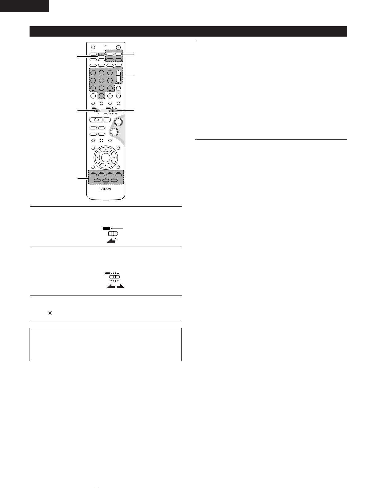
ENGLISH
+
-
+
-
RC-936
A / V
3
A-B REPEAT
SEARCH MODE
ONOFF
REPEAT RANDOM
CLEAR ZOOMSLIDE MODE
PROG/DIRECT
MEMO BANDMODE
STATUS
RETURN
ANGLE AUDIO
SUB TITLE
SETUP TONE/SDB
FUNCTIONSURROUNDINPUT MODETEST TONE
DVD
TUNER
CH
3
-
+
21
654
987
0
/
10
CALL
ENTER
MUTING
+
10
DISPLAY MENU
TOP MENU
SYSTEM MD
CDR TAPE
TUNER TV / VCR
SURROUND
PARAMETER
CH SELECT
VCR
NTSC/PAL
SLEEP
ENTER
CD SRS
EDIT/MENUCHARAC.
REC
TIMETITLE
TUNING /
TV VOL
TV CH TV CH
TUNERDVD
MD/LINE-1
TAPE/LINE-2
AUTO DECODE
VIRTUALDIRECT
5CH STEREO
STEREO
D.AUX
-
+
VCR CH
IN/SURR.
IN/SURR.
DVD
T VT V INSOURCE
9
8
21
76
+
-
3
-q
3
-w
12
3
-w
3
-q
A / V
SYSTEM
MD
CDR TAPE
TUNER TV / VCR
IN/SURR.
IN/SURR.
DVD
(5) Operating the TV/video deck after storing its remote control signals in the preset memory
Monitor TV (TV) and video deck (VCR) system buttons
q TV system buttons
3
TV : Power on/off
0~9 : Channel numbers
TV IN : TV input switching
TV VOL +, – : Volume up/down
TV CH +, – : Channel switching
w Video deck system buttons
VCR : Power on/off
VCR CH +, – : Channel switching
6, 7 : Manual search (fast-forward and fast-backward)
1 :Play
3 : Pause
2 : Stop
Set mode switch 1 to the “A/V” position.
1
Set mode switch 2 to the “TV/VCR” position.
2
Operate the video component.
• For details, refer to the component’s operating instructions.
3
NOTE:
• The TV’s “TV (POWER) and “TV IN” buttons can be operated as
It may not be possible to operate some models.
long as mode switch 1 is set to the “A/V” position, regardless of
the position of mode switch 2.
28
Page 29
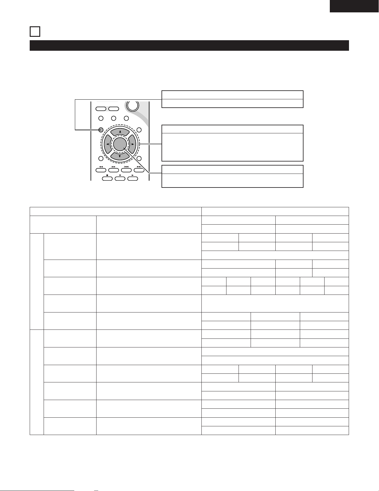
ENGLISH
10
SETTING UP THE SYSTEM
(1) System setup items
• Once all connections with other AV components have been completed as described in “CONNECTIONS” (see pages 8 to 15), make the various
settings described below on the monitor screen using the ADV-M71’s on-screen display function.
• Use the following buttons to set up the system:
SYSTEM SETUP button
Press this to display the system setup menu.
CURSOR buttons
0:Use these to move the cursors (
1
and
ª: Use these to move the cursors (
• and
and right
on the screen.
1
and down on the screen.
ENTER button
Press this to switch the display.
Also use this button to complete the setting.
and
• and
0) to the left
ª) to the up
ENTER
-
MUTING
VCR CH
-
SUB TITLE
76
STATU S
3
SETUP TONE/SDB
CH SELECT
RETURN
DISPLAY MENU
ANGLE AUDIO
SURROUND
PARAMETER
+
TOP MENU
Quick set up
Speaker Configuration
Delay Time
Channel Level
System Setup
DVD auto power off setting
Function Setting
Disc Setup
OSD Setup
Video Setup
DVD Setup
Audio Setup
Ratings
Other Setup
System setup items and default values (set upon shipment from the factory)
Setup
Set the screen size and the speaker system.
Input the combination of speakers in your system and
their corresponding sizes (SMALL for regular speakers,
LARGE for full-size, full-range) to automatically set the
composition of the signals output from the speakers and the
frequency response.
This parameter is for optimizing the timing with which the
audio signals are produced from the speakers and subwoofer
according to the listening position.
At the listening position, listen to the test tones output
from the different speakers and set so that the playback
level from the different speakers is equal.
The power automatically switches to standby if no
operation is performed for 30 minutes while in the stop
mode with the function set to DVD.
Set the LINE-1 and LINE-2 function names and turn the
analog recording output (REC OUT) on or off.
Set the audio language, subtitle language and disc menu
language for when playing discs.
Set the wallpaper for the setup and operation screens.
Set the screen size and video system for the TV being used.
Set the digital audio signal format and the linear PCM
sampling frequency and bit conversion.
Make the playback restriction setting for DVDs with
restricted viewing and set the password required for
changing the setting.
Make the closed caption setting for DVDs. (A commercially
available decoder is required to display the closed captions.)
Front L
0 dB
TV Aspect
4:3 PS
Front Sp.
Small
Front & Subwoofer Center
Center
“__”
LINE-1 LINE-2 REC OUT
MD TAPE ON
Dialog Subtitle Disc Menu
English
TV Aspect
4 : 3 PS
Digital Out
Normal
Rating Level
No Limit
Closed Caption
OFF
Default settings
2CH Virtual & SW
Center Sp.
“__”
Sw Freq. = 150 Hz / SW mode = None
Front R
0 dB
power does not turn off automatically
TV Type
NTSC
Surround Sp.
“__”
“__”
Surround R
“__”
OFF English
Wall Paper
Blue
Video Mode
AUTO
LPCM Select
Pass Word Change
0000 (Default)
Speaker
Surround L
“__”
OFF
Slide Show
5SEC
Sub Woofer
Ye s
Surround
“__”9ft (2.7m)
Sub Woofer
0 dB
Black level
LIGHTER
29
Page 30
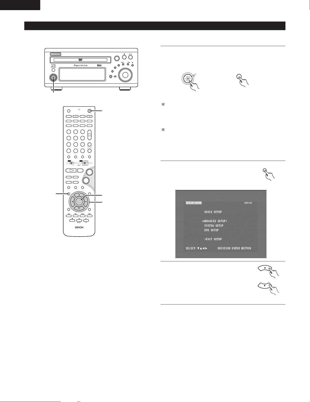
ENGLISH
ON / STANDBY
ON
B
BAND
PHONES
VOLUME
ON / STANDBY
DVD SURROUND RECEIVER ADV-M71
TONE/SDB
FUNCTION
MENU/SET
+
-
SURROUND/ SELECT
PUSH - PARAM.
VIRTUAL SPEAKER
1
+
-
+
-
RC-936
A / V
3
A-B REPEAT
SEARCH MODE
ONOFF
REPEAT RANDOM
CLEAR ZOOMSLIDE MODE
PROG/DIRECT
MEMO BANDMODE
STATUS
RETURN
ANGLE AUDIO
SUB TITLE
SETUP TONE/SDB
FUNCTIONSURROUNDINPUT MODETEST TONE
DVD
TUNER
CH
3
-
+
21
654
987
0
/
10
CALL
ENTER
MUTING
+
10
DISPLAY MENU
TOP MENU
SYSTEM MD
CDR TAPE
TUNER TV / VCR
SURROUND
PARAMETER
CH SELECT
VCR
NTSC/PAL
SLEEP
ENTER
CD SRS
EDIT/MENUCHARAC.
REC
TIMETITLE
TUNING /
TV VOL
TV CH TV CH
TUNERDVD
MD/LINE-1
TAPE/LINE-2
AUTO DECODE
VIRTUALDIRECT
5CH STEREO
STEREO
D.AUX
-
+
VCR CH
IN/SURR.
IN/SURR.
DVD
T VT V INSOURCE
9
8
21
76
+
-
1
2,12
3,5,7,9,10
4,6,8,11
SETUP
(2) Quick setup procedure
• Refer to “Connections” (pages 8 to 15) and check that all the connections are correct.
Turn on the power.
• The power indicator (LED) lights green, the power turns on
1
and the display lights.
Green
Main unit Remote control unit
Several seconds are required from the time the power button is
pressed until the power turns on. This is due to the built-in muting
circuit that turns off (mutes) the sound when the power is turned
on and off. The power indicator flashes green while the muting
circuit is activated.
Even when the power button has been pressed again and the
power has been set to the standby mode, power is still supplied to
some circuits. When leaving home or traveling, be sure to unplug
the power cord from the power outlet. In the standby mode, the
power indicator is lit red. The indicator is orange when the timer is
set.
30
Press the SETUP button to display the
setup screen.
2
Remote control unit
Use the
select “Quick System Setup”.
3
ª cursor buttons to
• and
• The selected item is displayed in
yellow.
Remote control unit
Page 31
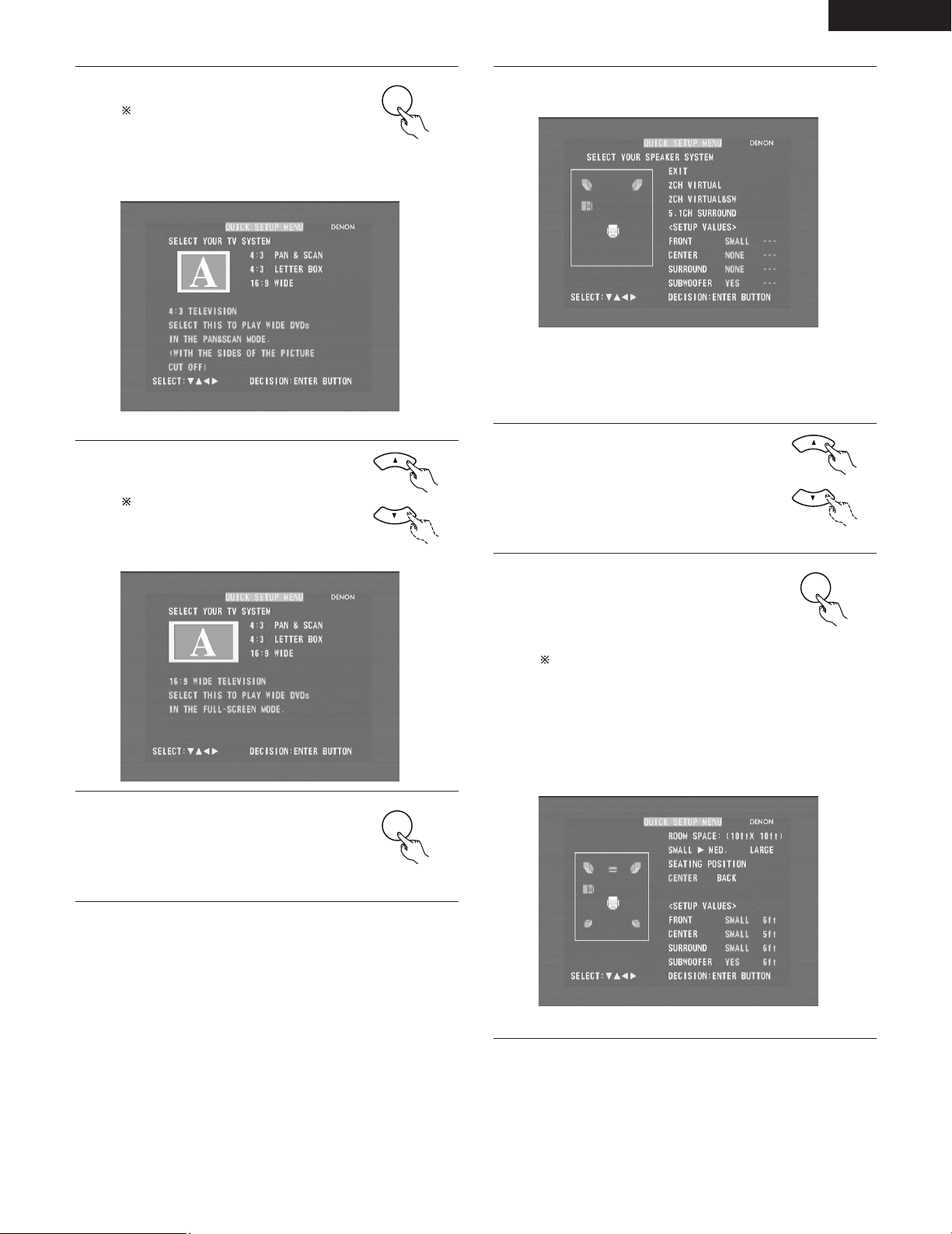
ENGLISH
ENTER
ENTER
ENTER
Press the ENTER button to display the
menu’s setting screen.
4
5
On the setting screen, the selected
item is displayed in yellow and the
values of the other items are
displayed in green.
[1] TV screen size setting
• The currently set value is displayed in yellow.
Use the
select the desired TV screen size and
display type.
The selected TV screen size is
displayed in yellow and the
description is displayed in green.
ª cursor buttons to
• and
Remote control unit
Remote control unit
[2] Speaker system settings
6
•“Return” is displayed in yellow.
• The currently set value is displayed in green.
• If you do not want to change the setting, press the ENTER
button at “Return”. The screen in step 2 reappears.
• To change the setting, proceed to step 7 below.
Use the
select the speaker system to be used.
7
Press the ENTER button to set the
selected setting.
8
• For settings other than “5.1-chanel
surround”, the setup screen in step 2
reappears.
The setup mode is quit in step 12.
/
The setup mode can also be quit by
using the
the setup screen to select “EXIT
SETUP” then pressing the ENTER
button.
• If “5.1-chanel surround” is selected,
the screen shown below appears.
[3] Room and listening position settings
ª cursor buttons to
• and
ª cursor buttons at
• and
Remote control unit
Remote control unit
Press the ENTER button to set the
selected setting.
6
• The screen shown below appears.
Remote control unit
• The currently set value is displayed in green.
31
Page 32
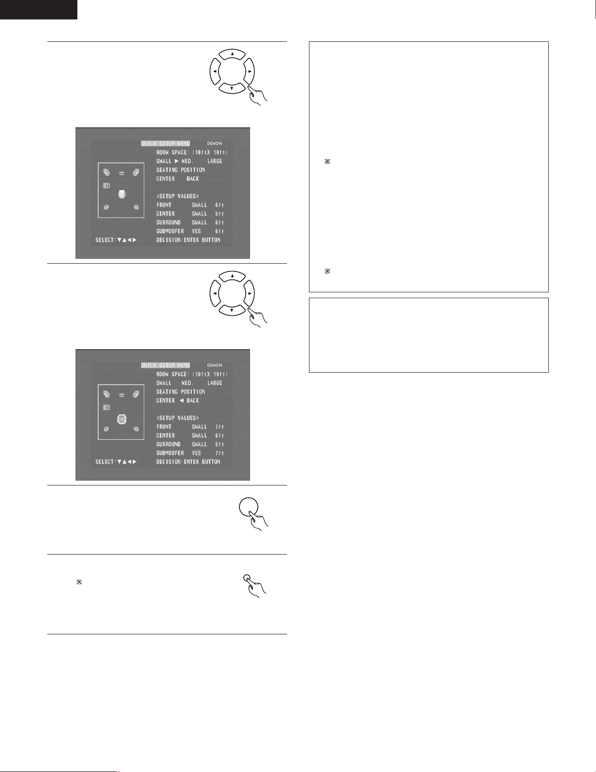
ENGLISH
ENTER
SETUP
Use the
9
to select “Room Settings”, then
use the
to set the size of the room.
• The set size is displayed in
Use the
10
to select “Listening Position”,
then use the
buttons to set the position.
• The set position is displayed in
yellow.
yellow.
• and
0
and
• and
ª cursor buttons
1 cursor buttons
ª cursor buttons
1 cursor
0
and
Remote control unit
Remote control unit
About the speaker system settings
B 2CH VIRTUAL
Select this when only using with the two speakers for the front
channels.
B 2CH VIRTUAL & SW
Select this when using two speakers for the front channels and
a subwoofer with built-in amplifier.
• Settings
Front : Small
Subwoofer : Yes
Subwoofer frequency : 150 Hz
Set the front speakers and subwoofer at equal distances.
B 5.1CH SURROUND
Select this when using two speakers for the front channels, a
center speaker, two speakers for the surround channels and a
subwoofer with built-in amplifier.
• Settings
Front : Small 9ft (2.7m)
Center : Small 8ft (2.4m)
Surround : Small 7ft (2.1m)
Subwoofer : Yes 9ft (2.7m)
Subwoofer frequency : 150 Hz
The room setting is set to “MED.”, the listening position to
“BACK”.
NOTE:
• The speaker system is set to “2CH VIRTUAL & SW” upon
shipment from the factory. It is not possible to achieve the
normal bass sound using this setting but with only speakers for
the two front channels. If only using speakers for the two front
channels, change the setting to “2CH VIRTUAL”.
Press the ENTER button to end the
settings.
11
• The screen in step 2 reappears.
Remote control unit
Press the SETUP button to quit the
setup mode.
12
The setup mode can also be quit by
using use the
at the setup screen to select “EXIT
SETUP” then pressing the ENTER
button.
ª cursor buttons
• and
Remote control unit
32
Page 33
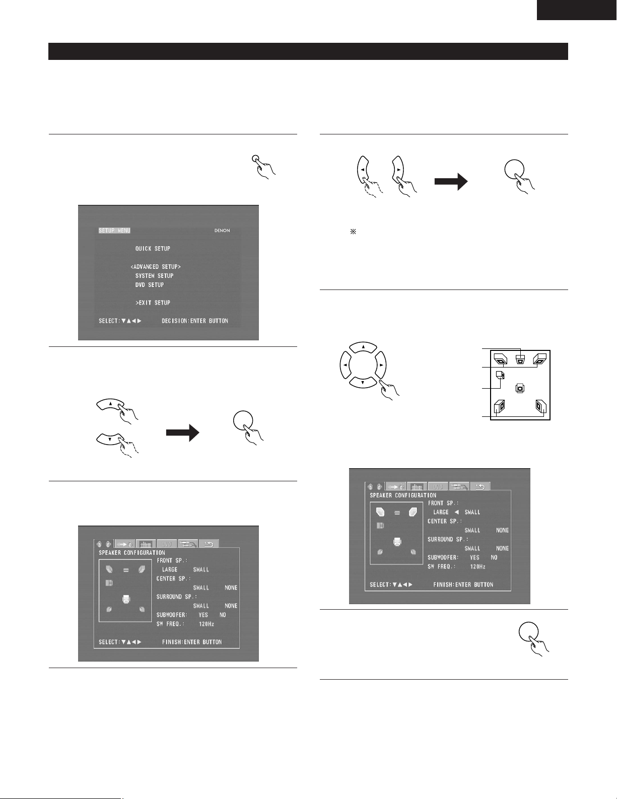
ENGLISH
SETUP
ENTER
ENTER
ENTER
(3) Detailed system setup (changing the system settings)
• The quick system settings and original settings set upon shipment from the factory are changed using the system setting changing menu. The
settings are stored in the memory until they are changed the next time, and remain valid even when the power is turned off.
[1] Speaker settings (type of speaker and whether or not the speaker is connected)
• The output component of the different channels and properties are adjusted automatically according to the combination of speakers actually
used.
Press the SETUP button to display the
setup screen.
1
Remote control unit
3
Remote control unit Remote control unit
When the cursor is at a tag icon on the system setting
changing menu screen, the settings screen can also be
selected by pressing the ª cursor button. You can return to
the tag icon by pressing the •cursor button.
• The speaker settings screen in step 4 appears.
Use the
under “<ADVANCED SETUP>”, then press the ENTER
2
button.
Remote control unit Remote control unit
At the system setting changing menu, use the
cursor buttons to select the “SPEAKER CONFIGURATION”
3
tag icon, then press the ENTER button.
ª cursor buttons to select “SYSTEM SETUP”
• and
Use the •, ª,
4
not the various speakers are connected, their size and other
parameters.
Remote control unit
• The item currently being set is displayed in yellow, and the
setting values for other items are displayed in green.
1
0
and
1 cursor buttons to select whether or
0
and
CENTER SPEAKER
FRONT SPEAKERS
SUB WOOFER
SURROUND
SPEAKERS
Press the ENTER button to enter the
settings.
5
• The next screen in the system setting
changing menu appears.
Remote control unit
33
Page 34
ENGLISH
NOTE:
• Select the speaker size not by the physical size of the speaker
but by the speaker’s capacity to reproduce low frequencies of
100 Hz or less. If you do not know, determine the best setting by
comparing the sound when the setting is set to “Small” and
“Large”, keeping the volume low enough to prevent damage to
the speaker.
NOTE:
• Select “Large” or “Small” not according to the actual size of the
speaker but according to the speaker’s capacity for playing low
frequency (approximately 100 Hz and below) signals. If you do
not know, try comparing the sound at both settings (setting the
volume to a level low enough so as not to damage the speakers)
to determine the proper setting.
Parameters
Large…… Select this when using speakers that can fully reproduce
low sounds of below 100 Hz.
Small…… Select this when using speakers that do not provide
sufficient volume for playing low frequencies of 100 Hz
and less. When this setting is made, frequencies below
the frequency set at the subwoofer frequency setting
are assigned to the subwoofer.
None…… Select this when no speakers are installed.
Yes/No…. Select “Ye s ” when a subwoofer is installed, “No” when
a subwoofer is not installed.
If the subwoofer has sufficient low frequency playback capacity,
good sound can be achieved even when “Small” is set for the
front, center and surround speakers.
For the majority of speaker system configurations, using the
SMALL setting for all five main speakers and Subwoofer On
with a connected subwoofer will yield the best results.
Subwoofer (SW FREQ.) frequency
• For the subwoofer frequency at the speaker setting screen, set
the bass crossover frequency for playback from the subwoofer.
• Select “80 Hz”, “120 Hz”, “150 Hz” or “180 Hz” (-6 dB for
each). Bass sound below these frequencies is played from the
subwoofer.
(This is set to “150 Hz” by factory default.)
Assignment of low frequencies
• In the Dolby Digital, Dolby Pro Logic II, DTS, and virtual surround
modes, the low frequency signals for channels whose speaker
settings are set to “Small” are assigned to the subwoofer. The
low frequencies of channels set to “Large” are played from
those channels.
(If set to “120 Hz”, channels set to “Small” play sounds of 120
Hz and greater, while bass frequencies of under 120 Hz are
played from the subwoofer.)
• In surround modes other than the ones listed above, low
frequencies below the frequency set at the subwoofer frequency
setting are played from the subwoofer regardless of whether the
speakers are set to “Large” or “Small”.
• Set the subwoofer frequency according to the low frequency
playback abilities of your speakers and subwoofer.
Subwoofer mode
• The subwoofer mode setting is only valid when “LARGE” is set
for the front speakers and “YES” is set for the subwoofer in the
“SPEAKER CONFIGURATION” settings.
• When the “LFE+MAIN” playback mode is selected, the low
frequency signal range of channels set to “LARGE” are produced
simultaneously from those channels and the subwoofer channel.
In this playback mode, the low frequency range expand more
uniformly through the room, but depending on the size and shape
of the room, interference may result in a decrease of the actual
volume of the low frequency range.
• Selection of the “LFE ” play mode will play the low frequency
signal range of the channel selected with “LARGE” from that
channel only. Therefore, the low frequency signal range that are
played from the subwoofer channel are only the low frequency
signal range of LFE (only during Dolby Digital or DTS signal
playback) and the channel specified as “SMALL” in the setup
menu.
• Select the play mode that provides bass reproduction with body.
• When the subwoofer is set to “YES”, bass sound is output from
the subwoofer regardless of the subwoofer mode setting in
surround modes other than Dolby/DTS.
34
Page 35
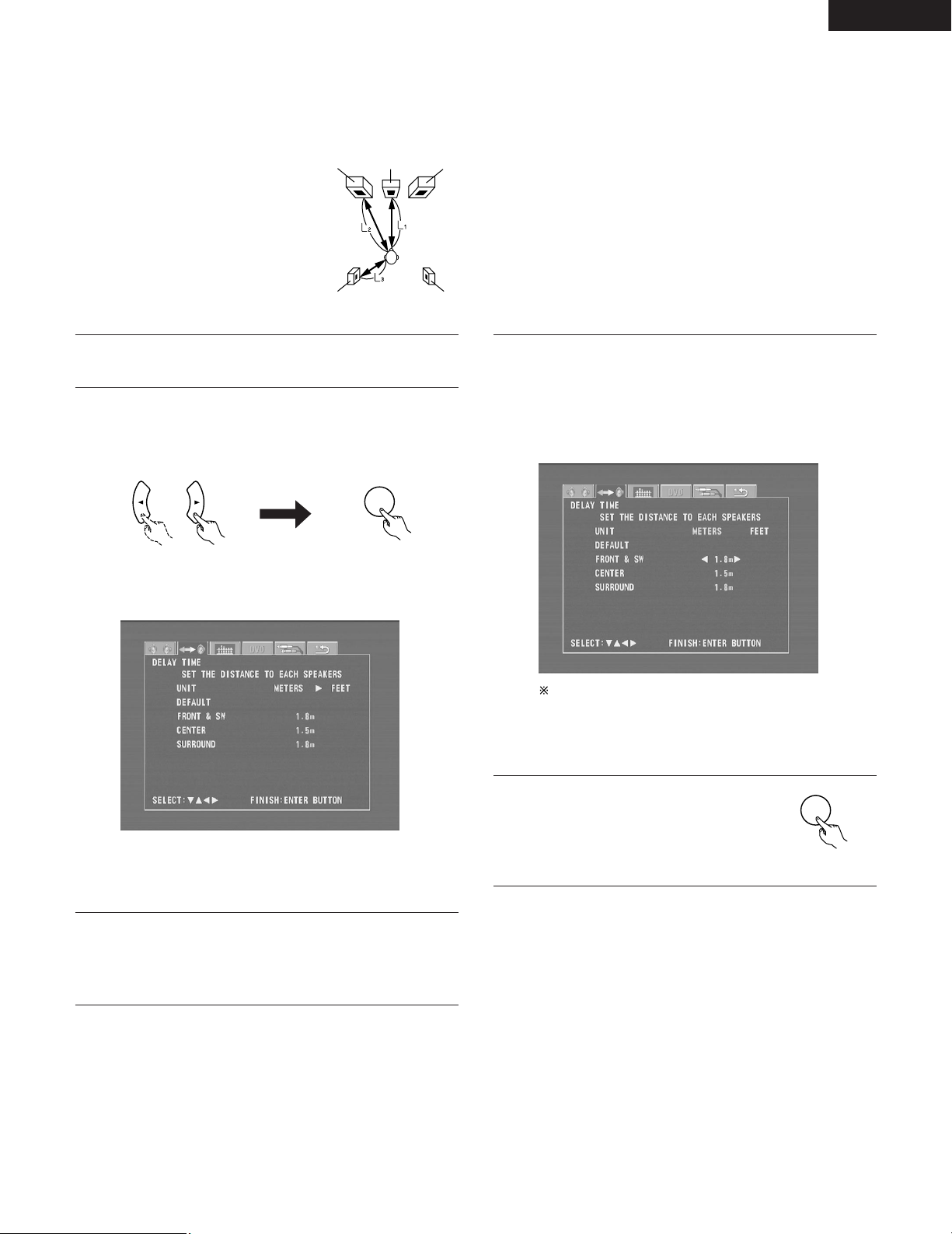
[2] Delay time (distance setting)
FRFL
SRSL
Center
ENTER
ENTER
• Input the distances from the listening position and the various speakers to set the surround delay time.
• Upon shipment from the factory default the delay time is set to the default values in step 3 below.
Preparation:
Measure the distance from the listening position to the various speakers.
L1
: Distance between center speaker
and listening position
2: Distance between front speakers
L
and listening position
L3: Distance between surround
speakers and listening position
Listening position
ENGLISH
If you are not at the system setting changing menu screen,
read step 1 and 2 on page 33.
1
At the system setting changing menu screen, use the
1 cursor buttons to select “DELAY TIME (Distance)”, then
2
press the ENTER button.
Remote control unit Remote control unit
• The delay time setting screen appears.
• The unit for the distance can be switched between “m”
(meters) and “ft” (feet) using the
If you do not want to change the unit, press the ª cursor
button to proceed to the next step.
1 cursor buttons.
0
and
Use the •and ª cursor buttons to select the speaker, then
4
use the
the speaker and the listening position.
0
and
• The distance changes by 0.1 meters (or 1 foot when the
unit is set to feet) each time the
pressed. Select the value closest to the measured distance.
Make sure the difference in the distances set for the
various speakers is no greater than 3.0 meters (10 feet).
If an inappropriate distance is set, “CAUTION: OUT OF
SETTING RANGE” is displayed. Change the position of the
speaker and make the setting over.
Press the ENTER button to enter the
settings.
5
• The next screen in the system setting
changing menu appears.
1 cursor buttons to set the distance between
0
and
1 cursor button is
0
and
Remote control unit
At “Default Value”, select “Ye s” to set the delay times for the
different speakers to the default values.
3
B Yes: The values are set to the defaults.
B No: The current settings are retained.
35
Page 36
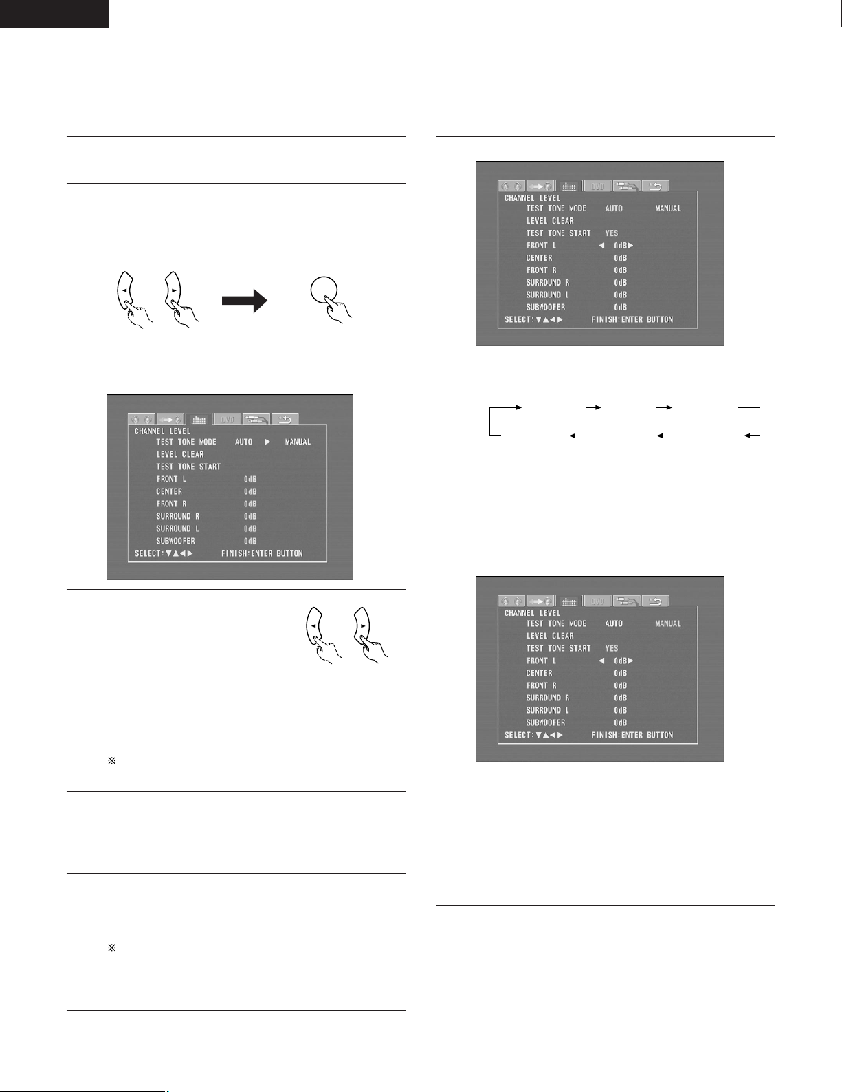
ENGLISH
ENTER
[3] Adjusting the channel level
• Adjust so that the playback levels of the different channels are equal.
• Make this adjustment by listening to the test tones output from the speakers at the listening position.
• By factory default all the levels of all the channels are set to 0 dB.
• This adjustment can also be made directly from the remote control unit. (CH SELECT Button)
If you are not at the system setting changing menu screen,
1
read step 1 and 2 on page 33.
At the system setting changing menu screen, use the
2
1 cursor buttons to select “Channel Level Adjustment”, then
press the ENTER button.
Remote control unit Remote control unit
• The channel level adjustment screen appears.
q When “Auto” is selected at “Test Tone”:
6
0
and
• Test tones are automatically output from the speakers at
intervals of 4 seconds for two of the cycles shown below,
then at intervals of 2 seconds from the third cycle on.
Front left Center Front right
Surround rightSurround left Subwoofer
Use the
so that the volume of the test tones output from the different
speakers sounds the same.
• The level changes in units of 1 dB each time the
cursor button is pressed.
The level can be adjusted in the range –12 dB to +12 dB.
1 cursor buttons to adjust the channel levels
0
and
1
0
and
Use the
3
select “Auto” or “Manual” for the
“Test Tone” mode.
• The selected setting is displayed
in yellow.
B Auto: Adjust the levels listening to test tones
B Manual: Select the speakers from which the test tones are
Detailed settings can be made when this is set to
“Manual” first.
When “Yes ” is selected at “Level Clear”, the level settings
4
for all the speakers are set to 0 dB.
B Yes: The level settings for all the speakers are set to 0 dB.
B No: The currently set level settings are retained.
Adjust the channel levels in the test tone mode.
5
Use the •and ª cursor buttons to select the “Test Tone
Start” mode, then use the 0cursor button to select “Ye s”.
The test tone is output.
Use the MASTER VOLUME control on the main unit or the
VOLUME buttons on the remote control unit to adjust the
volume of the test tone to a level at which it is easy to
make this adjustment.
1 cursor buttons to
0
and
Remote control unit
automatically output from the different speakers.
output when adjusting the levels.
w When “Manual” is selected at “Test Tone”:
Use the •and ª cursor buttons to select the speaker from
which the test tone is to be output, then use the
cursor buttons to adjust the channel levels so that the volume
of the test tones output from the different speakers sounds
the same.
• The level changes in units of 1 dB each time the
cursor button is pressed.
The level can be adjusted in the range –12 dB to +12 dB.
0
and
0
and
1
1
36
Page 37
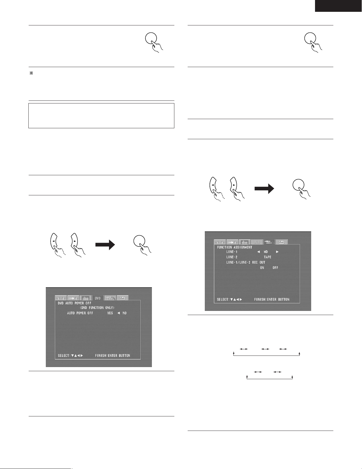
ENGLISH
ENTER
ENTER
ENTER
MD
CD-R
AUX
MD/CD-R
TAPE D.AUXAUX
ENTER
Press the ENTER button to enter the
settings.
7
• The next screen in the system setting
changing menu appears.
Remote control unit
To cancel the settings after the adjustments have been made
Display the channel level adjustment screen, then use the •, ª,
1 cursor buttons to select “Level Clear” and select “Ye s ”.
and
The level settings for all the speakers are set to 0 dB.
NOTE:
When the channel levels are adjusted at the channel level settings,
the adjusted values are applied to all playback modes.
[4] DVD Auto Power Off setting
• The ADV-M71 is equipped with a function for automatically setting
the power to the standby mode if no operation is performed for 30
minutes when the function is set to DVD. Here set whether to use
this function or not.
• By factory default this is set to “No”.
If you are not at the system setting changing menu screen,
1
read step 1 and 2 on page 33.
At the system setting changing menu screen, use the
2
1 cursor buttons to select “DVD AUTO POWER OFF”, then
press the ENTER button.
0
and
Press the ENTER button to enter the
settings.
4
• The next screen in the system setting
changing menu appears.
Remote control unit
0
[5] Function settings
• Set the LINE-1 and LINE-2 function names and turn the analog
recording output (REC OUT) on or off.
• When used in combination with the D-M31 series, set according to
the components being used and make system connections for
convenient system functions.
• It is also possible to assign the D.AUX digital input to LINE-2.
If you are not at the system setting changing menu screen,
1
read step 1 and 2 on page 33.
At the system setting changing menu screen, use the
2
1 cursor buttons to select “FUNCTION ASSIGNMENT”, then
press the ENTER button.
Remote control unit Remote control unit
• The input function setting screen appears.
0
and
3
Remote control unit Remote control unit
• The DVD auto power off setting screen appears.
Use the
Off” mode.
B Yes: The function for automatically turning the power off
when the function is set to DVD is activated.
B No: The auto power off function is not activated.
1 cursor buttons to select the “Auto Power
0
and
Use the •and ª cursor buttons to select the item to be set,
3
then use the
B LINE-1 Function name selection (“MD” by default)
B LINE-2 Function name selection (“TAPE” by default)
B LINE-1/LINE-2 REC OUT
: Set whether to turn the recording output during playback in
the Dolby Virtual Speaker mode when the function set to
DVD or the D.AUX exclusive digital input on or off.
On : The signals are output in stereo. (Factory default)
Off : The signals are not output. (Recording is not
possible.)
1 cursor buttons to make the settings.
0
and
37
Page 38
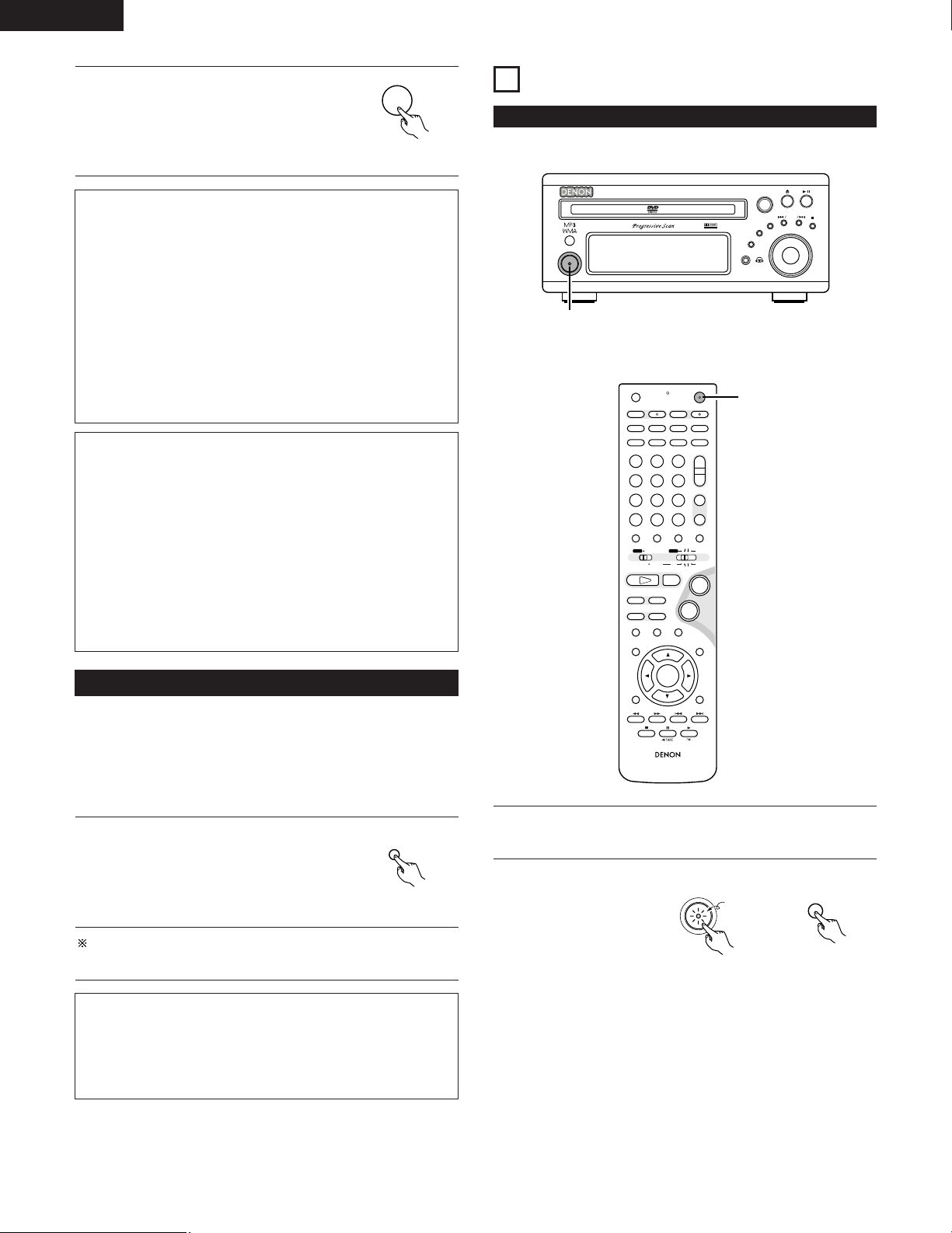
ENGLISH
ENTER
SETUP
B
BAND
PHONES
VOLUME
ON / STANDBY
DVD SURROUND RECEIVER ADV-M71
TONE/SDB
FUNCTION
MENU/SET
+
-
SURROUND/ SELECT
PUSH - PARAM.
VIRTUAL SPEAKER
2
+
-
+
-
RC-936
A / V
3
A-B REPEAT
SEARCH MODE
ONOFF
REPEAT RANDOM
CLEAR ZOOMSLIDE MODE
PROG/DIRECT
MEMO BANDMODE
STATUS
RETURN
ANGLE AUDIO
SUB TITLE
SETUP TONE/SDB
FUNCTIONSURROUNDINPUT MODETEST TONE
DVD
TUNER
CH
3
-
+
21
654
987
0
/
10
CALL
ENTER
MUTING
+
10
DISPLAY MENU
TOP MENU
SYSTEM MD
CDR TAPE
TUNER TV / VCR
SURROUND
PARAMETER
CH SELECT
VCR
NTSC/PAL
SLEEP
ENTER
CD SRS
EDIT/MENUCHARAC.
REC
TIMETITLE
TUNING /
TV VOL
TV CH TV CH
TUNERDVD
MD/LINE-1
TAPE/LINE-2
AUTO DECODE
VIRTUALDIRECT
5CH STEREO
STEREO
D.AUX
-
+
VCR CH
IN/SURR.
IN/SURR.
DVD
T VT V INSOURCE
9
8
21
76
+
-
2
ON / STANDBY
ON
Press the ENTER button to enter the
settings.
4
• The next screen in the system setting
changing menu appears.
Remote control unit
Input function settings
• LINE-1 and LINE-2 can be set as described below.
LINE-1 : “MD”, “CD-R”, “MD/CD-R” or “AUX” can be
selected.
(“MD/CD-R” can only be set when a system MD
recorder, cassette deck and CD recorder are all
connected and system operations are being used.)
LINE-2 : This can be set to “TAPE”, “MD”, “AUX” or “D.AUX”.
(Set “D.AUX” to use the D.AUX digital input in
combination with the LINE-2 analog input.)
• The setting for LINE-1 has priority. Once a function is set for
LINE-1, it is not possible to set the same function for LINE-2. (For
example, if “MD” is selected for LINE-1, “MD” is no longer
offered as one of the choices for LINE-2.)
LINE-1/LINE-2 analog recording output setting
• Normally set this to “On”.
• With the DVD or D.AUX exclusive digital input function, set this
to “Off” if noise is generated when playing sources with high bit
rates in the Dolby Virtual Speaker mode.
• This setting is only valid in the Dolby Virtual Speaker mode for the
DVD or D.AUX exclusive digital input function. (In surround
modes other than the Dolby Virtual Speaker mode and with other
input functions, analog recording signals are output, regardless of
this setting.)
• Analog recording is not possible when this is set to “Off”. To
record, use a mode other than the Dolby Virtual Speaker mode
(stereo, for example).
11
PLAY BACK
(1) Before Operating
(4) After changing the system settings
• This completes the procedure for changing the system settings.
Once the speaker settings, delay times and channel levels have
been set, there is no need to change the settings again unless the
connected AV components or speakers are changed or the
speakers are moved to different positions.
• DVD auto power off and function settings as necessary.
At the system setting changing menu
screen, press the SETUP button.
1
• The new settings are entered and the
on-screen display turns off.
The setup procedure can be quit at any point by pressing this
button.
NOTE:
• When system settings have been changed with the system
setting changing menu and a speaker system is selected with
the quick system settings, the speaker settings and delay time
settings are changed to the values preset for the quick system
settings.
38
Remote control unit
Refer to “CONNECTIONS” (pages 8 to 15) and check that all
connections are correct.
1
Turn on the power.
Press the POWER
2
button.
Light
(green)
Main unit Remote control unit
When pressed, the power turns on and the display lights. The
sound is muted for several seconds, after which the unit
operates normally. When pressed again, the power turns off,
the standby mode is set and the display turns off.
Whenever the ON/STANDBY button is in the STANDBY state,
the apparatus is still connected on AC line voltage. Please be
sure to unplug the cord when you leave home for, say, a
vacation.
Page 39
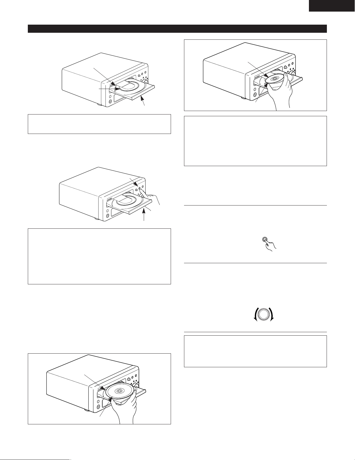
(2) Loading Disc
MENU/ SET
SURROUND/ SELECT
PUSH - PARAM.
2
Set discs in the disc tray with the labeled (printed) side facing up.
ENGLISH
Figure 2
12 cm disc guide
8 cm disc guide
Disc tray
NOTE:
• Do not move the this unit while a disc is playing. Doing so
may scratch the disc.
(1) Opening and Closing the Disc Tray
q Turn on the power.
w Press the OPEN/CLOSE button.
OPEN/CLOSE button
Disc tray
NOTES:
• Even when the power is in the standby mode, when the
OPEN/CLOSE button is pressed, the ADV-M71’s power turns
on and the disc tray operates. (Auto power on function)
• Even if the function is set to something other than DVD,
when the OPEN/CLOSE button is pressed, the function
switches to DVD and the disc tray operates. (Auto function
select function)
• Do not strike on the button with a pencil, etc.
(2) Loading Discs
• Pick up the disc carefully so as not to touch the signal surface and
hold it with the labeled side facing up.
• With the disc tray fully open, set the disc in the disc tray.
• Set 12 cm discs in the outer tray guide (Figure 1), 8 cm discs in the
inner tray guide (Figure 2).
• Press the OPEN/CLOSE button. The disc is automatically loaded.
• The disc tray can also be closed automatically to load the disc by
pressing the PLAY button.
Figure 1
Outer disc tray
Inner disc tray
8 cm disc
NOTES:
• If a foreign object is caught in the disc tray during closing,
simply press the OPEN/CLOSE button again and the tray will
open.
• Do not press the disc tray in by hand when the power is off.
Doing so will damage it.
• Do not place foreign objects in the disc tray. Doing so will
damage it.
(3) Selecting the video output
• Factory default: interlace, 525i.
• When a TV compatible with progressive 525p inputs is connected,
the setting can be switched using the operation described below.
With the function set to “DVD”, press the MENU/SET
button for at least 2 seconds.
1
• The current setting (“INTERLACED” or “PROGRESSIVE”)
is displayed after “VIDEO OUT”.
Main unit
Turn the surround/select control while the setting is
displayed to switch it.
2
• The setting switches alternately between “INTERLACED”
and “PROGRESSIVE”.
• The normal display reappears if no operation is performed
for several seconds.
Main unit
NOTE:
• When “PROGRESSIVE” is set, no video signals are output
from the VIDEO OUT or S-VIDEO OUT terminals. Set
“INTERLACED” if you want to use the VIDEO OUT or SVIDEO OUT signals.
12 cm disc
39
Page 40
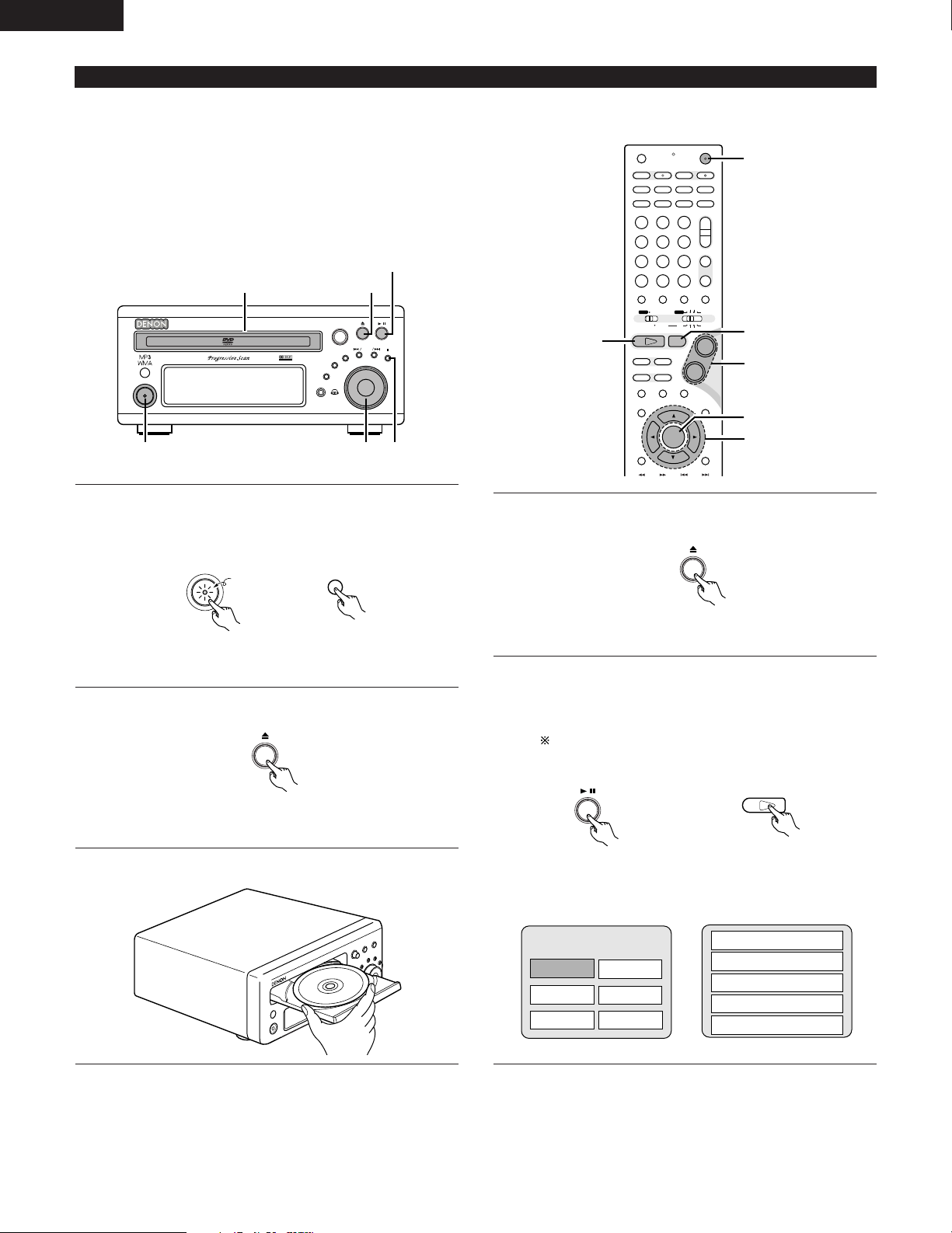
ENGLISH
ON
ON / STANDBY
DVD
1
B
BAND
PHONES
VOLUME
ON / STANDBY
DVD SURROUND RECEIVER ADV-M71
TONE/SDB
FUNCTION
MENU/SET
+
-
SURROUND/ SELECT
PUSH - PARAM.
VIRTUAL SPEAKER
(3)-1 (3)-8
(3)-3 (3)-2,(3)-4
(3)-5
(4)-1
+
-
+
-
A / V
3
A-B REPEAT
SEARCH MODE
ONOFF
REPEAT RANDOM
CLEAR ZOOMSLIDE MODE
PROG/DIRECT
MEMO BANDMODE
STATUS
SETUP TONE/SDB
FUNCTIONSURROUNDINPUT MODETEST TONE
DVD
TUNER
CH
3
-
+
21
654
987
0
/
10
CALL
ENTER
MUTING
+
10
SYSTEM MD
CDR TAPE
TUNER TV / VCR
SURROUND
PARAMETER
CH SELECT
VCR
NTSC/PAL
SLEEP
ENTER
CD SRS
EDIT/MENUCHARAC.
REC
TIMETITLE
TUNING /
TV VOL
TV CH TV CH
TUNERDVD
MD/LINE-1
TAPE/LINE-2
AUTO DECODE
VIRTUALDIRECT
5CH STEREO
STEREO
D.AUX
-
+
VCR CH
IN/SURR.
IN/SURR.
DVD
T VT V INSOURCE
9
8
21
76
+
-
(3)-1
(3)-6
(3)-7
(3)-8
(3)-5
(4)-1
(3) Playback
IMPORTANT SETUP INFORMATION
This set has the following presettings:
“DISC SETUP”, “OSD SETUP”, “VIDEO SETUP”, “AUDIO SETUP”,
“RATINGS”, and “OTHER SETUP”.
These presettings have been preset upon shipment from the factory.
If you wish to change them to suit your specific purposes, refer to
pages 91 to 103.
Turn on the power.
• Press the power button, the power indicator lights and the
1
power turns on.
Light
(green)
Main unit
Press the OPEN/CLOSE button to open the disc tray.
2
Main unit
Set the disc in the disc tray.
3
40
Remote control unit
Press the OPEN/CLOSE button.
4
Main unit
Press the PLAY button.
• For many interactive DVDs and video CDs with playback
5
control, a menu screen appears. In this case use the
procedure in step 6 to select the desired item.
Interactive DVDs are DVDs including multiple angles,
stories, etc.
Main unit
Example: For DVDs with menu
screens
TOP MENU
Apple
Orange
Peach
Banana
Strawberry
Pineapple
Remote control unit
Example: For video CDs with
playback control
1. Opening
2. 1st movement
3. 2nd movement
4. 3rd movement
5. Ending
Page 41
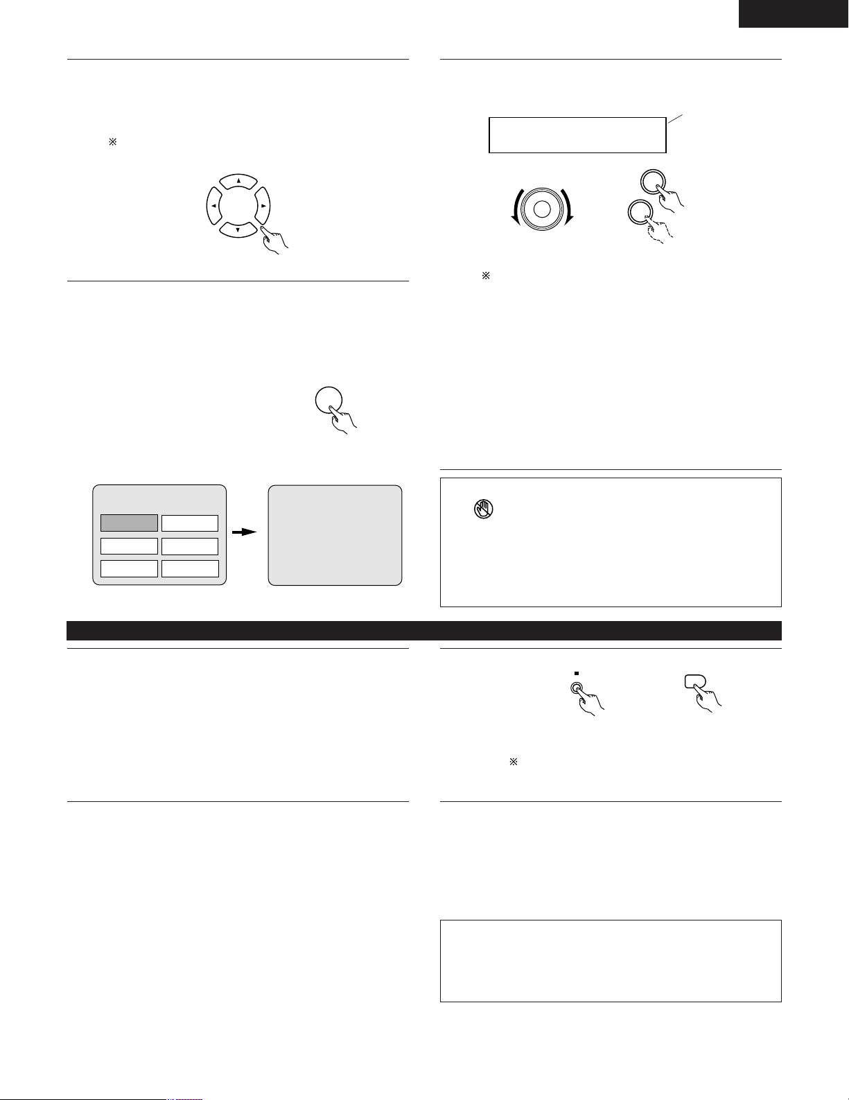
ENGLISH
ENTER
M.VOLUME -20
+
-
VOLUME
2
BAND
Use the cursor buttons (•, ª,
item.
6
• For some discs there is a second menu screen. If so, press
the 9 button to display the next menu screen. (See the
disc’s jacket.)
The cursor buttons (•, ª,
CDs. Use the number buttons to select the desired item.
Remote control unit
Press the ENTER button.
• The desired item is selected and playback starts.
7
• You can return to the menu screen by pressing the TOP
MENU button while the DVD is playing, though this
depends on the disc.
• Press the RETURN button during playback of a video CD to
return to the menu screen.
Example: When “Apple” is
selected
TOP MENU
Apple
Orange
Peach
Banana
Strawberry
Pineapple
1) to select the desired
0
and
1) do not work for video
0
and
Remote control unit
Apple
Either turn the main unit’s main volume control or use the
main volume control buttons on the remote control unit to
8
adjust the volume.
The volume is shown
on the display.
Main unit Remote control unit
For detailed instructions on operations for the surround
modes and surround parameters, see “12 Operating the
Surround Functions” on pages 43 to 61.
• In the “AUTO” input mode, the signals of the disc being
played are identified, Dolby Digital, DTS or PCM decoding
is selected automatically and the disc is played.
• In the Dolby Virtual Speaker surround mode, the signals of
the disc being played are automatically decoded in Dolby
Digital or DTS then played in the Dolby Virtual Speaker
surround mode.
• In the “AUTO DECODE” surround mode when a 5.1channel speaker system is set, the signals of the disc being
played are identified and automatically decoded in Dolby
Digital, DTS or Auto Stereo and the disc is played.
NOTES:
• If appears on the TV screen while buttons are being
operated, that operation is not possible on the ADV-M71 or with
that disc.
• Set the disc in the disc guide.
• Only set one disc in the tray.
• The disc keeps turning while the menu screen is displayed on the
TV screen.
(4) Stopping Playback
During playback, press the STOP button on the main unit or
the remote control unit, playback stops and wall paper is
1
displayed.
<Resume play memory function (DVD only)>
• With the ADV-M71, when the STOP button is pressed, that
position is stored in the memory. At this time, “1” flashes
on the display. When the PLAY button is pressed after
pressing the STOP button, playback resumes from the
position at which it was stopped.The resume play memory
function is canceled if the disc tray is opened or the STOP
button is pressed a second time.
About the DVD standby function
When the ADV-M71’s function is set to DVD, the DVD
standby mode is set automatically if the disc remains in the
stop mode for approximately 10 minutes.
• In the DVD standby mode, the DVD section’s power is
off and output of the video signals is also off.
The ADV-M71’s display reads “DVD standby” at this
time.
• When in the DVD standby mode, the power of the
sections other than the DVD section is on and function
switching and other operations can be performed on the
main unit and remote control unit. When a DVD control
button (the play/pause and button open/close buttons on
the main unit, the play button on the remote control unit,
etc.) is operated, the DVD section’s power turns on
automatically and disc playback and opening/closing of
the disc holder can be performed.
Main unit Remote control unit
The resume play memory function only works for
discs for which the elapsed time is shown on the
display during playback.
Auto power off function.
• The ADV-M71 is equipped with a function that
automatically switches the power to standby if no
operation is performed for 30 minutes while in the stop
mode with the function set to DVD.
• This function is set to off upon shipment from the
factory. If you wish to turn it on, set the “DVD AUTO
POWER OFF” setting to “YES” as described on page 37.
NOTE:
• The DVD standby function only turns off the power of the DVD
section. It is different from the DVD auto power off function set
with the system settings in Setup in that the DVD section
remains functional.
41
Page 42
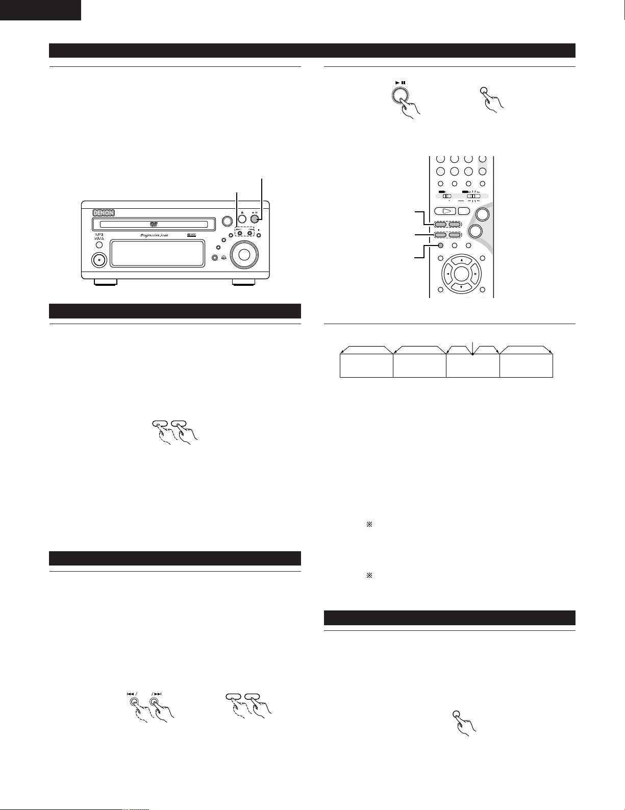
ENGLISH
3
B
BAND
PHONES
VOLUME
ON / STANDBY
DVD SURROUND RECEIVER ADV-M71
TONE/SDB
FUNCTION
MENU/SET
+
-
SURROUND/ SELECT
PUSH - PARAM.
VIRTUAL SPEAKER
(7)-1
(5)-1
+
-
A / V
3
STATUS
SETUP TONE/SDB
FUNCTIONSURROUNDINPUT MODETEST TONE
DVD
CH
987
0
/
10
CALL
ENTER
MUTING
+
10
SYSTEM MD
CDR TAPE
TUNER TV / VCR
SURROUND
PARAMETER
CH SELECT
VIRTUALDIRECT STEREO
-
+
VCR CH
IN/SURR.
IN/SURR.
DVD
9
8
21
76
+
-
(5)-1,(8)-1
(6)-1,(9)-1
(7)-1
76
+
-
9
8
3
(5) Playing Still Pictures (Pausing)
1
During playback, press the 13 button on the main unit or the
3 button on the remote control unit.
• Press the PLAY button to resume normal playback.
Main unit Remote control unit
1
1
42
(6) Forward / Reverse Searching
During playback, press one of the 6 / 7 buttons on the
remote control unit.
6 : Reverse direction
7 : Forward direction
• When pressed again, the search speed increases (DVD,
VIDEO CD in seven steps, CD in four steps).
• Press the PLAY button to resume normal playback.
Remote control unit
NOTE:
• In some cases the menu screen may reappear when one of
the 6 / 7 buttons is pressed during menu playback on
a video CD.
(7) Skipping to the Beginning of Chapters or Tracks
During playback, press one of the skip buttons on the main
unit or the remote control unit.
8 / : Reverse direction (PREVIOUS)
9 / : Forward direction (NEXT)
• A number of chapters or tracks equal to the number of
times the button is pressed is skipped.
• When the skip back button is pressed once, the pickup
returns to the beginning of the currently playing chapter or
track.
Main unit Remote control unit
Playing position
Chapter/Track Chapter/Track Chapter/Track Chapter/Track
Reverse direction
Forward direction (direction of playback)
,/
NOTE:
• In some cases the menu screen may reappear when one of
the 8 / 9 buttons is pressed during menu playback
on a video CD.
Searching using the number buttons
q During playback, press the search mode button on the
remote control unit.
• The mode switches as shown below each time the
button is pressed:
For DVDs : Title
,/
Chapter
For CDs and video CDs : Track (no switching)
The search mode set by pressing the search mode
button is stored in the memory until the power is
turned off.
w Use the number buttons on the remote control unit to
input the number of the title, chapter or track to be played.
Some DVDs or video CDs may be designed to operate
in special ways and will not operate as described here.
(8) Playing Frame by Frame (for DVDs and video CDs only)
During playback, press the 3 button on the remote control
unit.
1
• The picture moves forward one frame each time the button
is pressed.
• Press the PLAY button to resume normal playback.
Remote control unit
Page 43
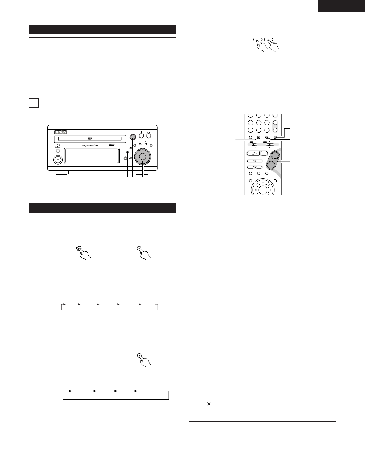
(9) Slow Playback (for DVDs and video CDs only)
76
B
BAND
PHONES
VOLUME
ON / STANDBY
DVD SURROUND RECEIVER ADV-M71
TONE/SDB
FUNCTION
MENU/SET
+
-
SURROUND/ SELECT
PUSH - PARAM.
VIRTUAL SPEAKER
5
1
3
+
-
-
A / V
3
STATUS
SETUP TONE/SDB
FUNCTIONSURROUNDINPUT MODETEST TONE
DVD
TUNER
CH
654
987
0
/
10
CALL
ENTER
MUTING
+
10
SYSTEM MD
CDR TAPE
TUNER TV / VCR
AUTO DECODE
VIRTUALDIRECT
5CH STEREO
STEREO
IN/SURR.
IN/SURR.
DVD
9
8
21
76
+
-
5
2
3
1
FUNCTION
FUNCTION
DVD
TUNER (LINE2)
D.AUX
(LINE1)
INPUT MODE
AUTO PCM DTS ANALOG
In the still mode, press one of the 6 / 7 buttons on the
remote control unit.
1
12
OPERATING THE SURROUND FUNCTIONS
6 : Reverse direction
7 : Forward direction
• When pressed again, the slow play speed increases.
(Four step) (Three step on video CDs)
• Press the PLAY button to resume normal playback.
ENGLISH
Remote control unit
NOTE:
• Reverse slow play is not possible on video CDs.
Input mode setting
Press the FUNCTION button to select the input function to be
played.
1
Main unit Remote control unit
• The function switches as shown below.
• Factory default (LINE 1) = MD, (LINE 2) = TAPE
When DVD, D.AUX or (LINE1) = MD was selected as the
input function, press the remote control unit’s INPUT MODE
2
button to select the input mode.
•“ANALOG” cannot be selected when DVD or D.AUX was
•“ANALOG” can be selected when “LINE-2” is set to
selected as the input function.
“D.AUX” at “FUNCTION ASSIGNMENT” under “SYSTEM
SETUP” in the detailed settings.
Input mode selection function
• The input mode can be selected when the input function is
set to DVD, D.AUX or (LINE1) = MD.
• Different input modes can be selected for each input
function. The selected input mode is stored in the memory
for the individual input functions.
• When the input function is set to something other than the
above, “ANALOG ONLY” is displayed and the input mode
cannot be selected.
q AUTO (auto mode)
In this mode, the type of signal being input to the digital
and analog input terminals is detected and the program in
the set’s surround decoder is switched automatically to
play the signals for the selected input function.
The presence or absence of digital signals is detected, the
signals input to the digital input are identified and decoding
and playback are performed automatically in DTS, Dolby
Digital or PCM (2 channel stereo) format.
If no digital signal (LINE1) = MD is being input, the analog
input jacks are selected.
Use this mode to play Dolby Digital signals.
w PCM (exclusive PCM signal playback mode)
Decoding and playback are only performed when PCM
signals are being input.
e DTS (exclusive DTS signal playback mode)
Remote control unit
Decoding and playback are only performed when DTS
signals are being input.
r ANALOG (exclusive analog audio signal playback mode)
The signals input to the analog input jacks are played.
This cannot be selected in the DVD mode.)
(
The input mode automatically switches to “AUTO” if you
switch the input function to DVD from anything other than
DVD.
43
Page 44
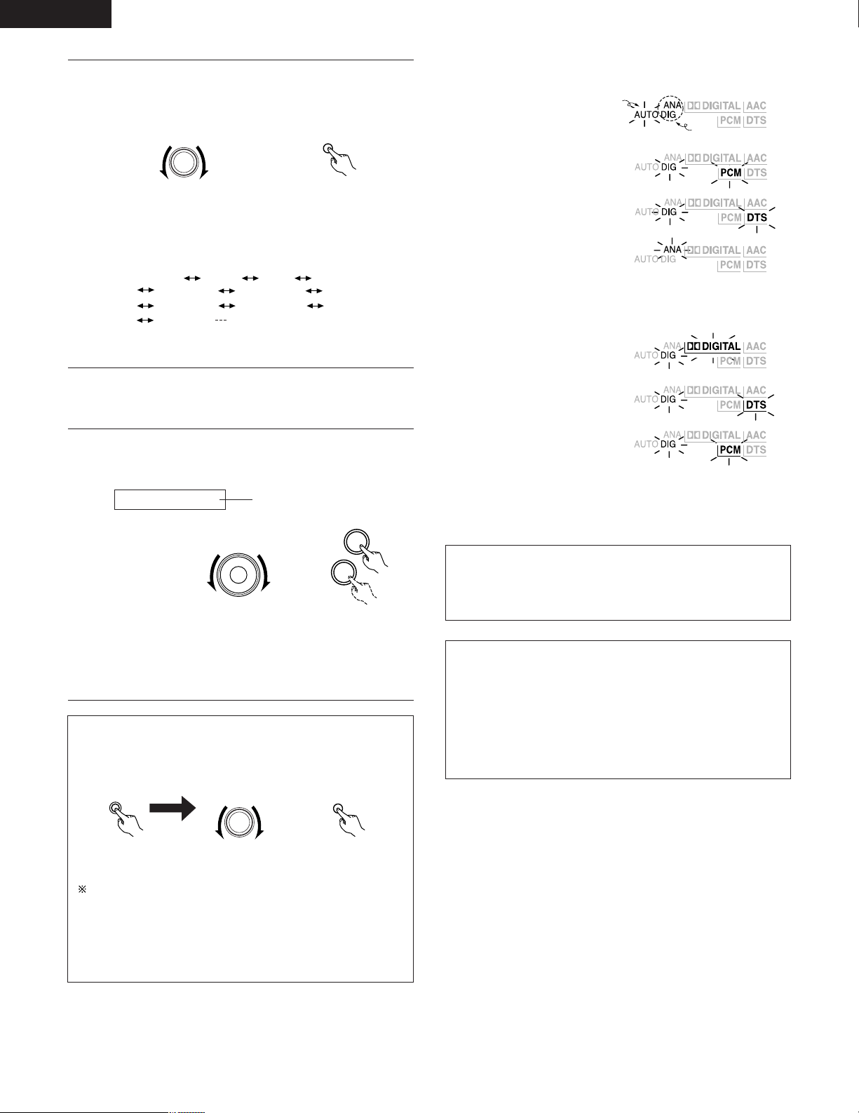
ENGLISH
SURROUND/ SELECT
PUSH - PARAM.
SURROUND
DOLBY VS STEREO *AUTO DECODE
*5CH STEREO *MONO MOVIE
ROCK ARENA
DIRECT
JAZZ CLUB
DOLBY VS
VIDEO GAME *MATRIX
+
-
SURROUND/ SELECT
PUSH - PARAM.
STATU S
Either turn the SURROUND/SELECT dial or press the
SURROUND button on the remote control unit to select the
3
surround mode.
Main unit Remote control unit
• The function switches as shown below.
• The function only changes in the “Æ” direction when
operated from the remote control unit.
• The modes marked “*” can be selected when “5.1channel surround” is selected in the quick system setup.
Start playback on the selected component.
• For operating instructions, refer to the component’s
4
5
manual.
Either turn the MASTER VOLUME dial on the main unit or
use the VOLUME buttons on the remote control unit to
adjust the volume.
Input mode display
• In the AUTO mode
• In the DIGITAL PCM mode
• In the DIGITAL DTS mode
• In the ANALOG mode
Input signal display
• DOLBY DIGITAL
• DTS
• PCM
Lit
One of these lights, depending on
the input signal.
M.VOLUME -20
• The volume can be adjusted within the range –60 to 0 to
+18 dB. Note that depending on the input signal, surround
mode, speaker settings and channel level setting, it may
not be possible to adjust the volume up to +18 dB.
The volume level is displayed
on the display.
VOLUME
Main unit
Remote control unit
2 To check the currently playing program source, etc.
Press the MENU/SET button. Display “STATUS” then turn
the SURROUND/SELECT control.
MENU/ SET
Main unit
Main unit
Remote control unit
To perform this operation on the remote control unit, press
the STATUS button.
The current program source and surround settings are shown
on the display each time the button is pressed or turned.
(When the function is set to DVD, the information is also
displayed on the TV screen.)
•“DIG” lights when digital signals are input properly. If “DIG” is
flashing, check whether the connections are proper and whether
the input component’s power is on.
Input mode when playing CD sources
• When playing CDs containing recordings of live concerts, etc., in
the “AUTO” mode, the sound may be slightly broken at the
beginning. If this happens, switch to the “PCM” mode.
Input mode when playing DTS sources
• If DTS-compatible CDs are played in the “PCM” mode, noise is
output because DTS playback is not possible.
To play a DTS-compatible source, be sure to set the input mode
to “AUTO” or “DTS”.
• Noise may be generated at the beginning of playback and while
searching during DTS playback in the AUTO mode. If so, play in
the DTS mode.
44
Page 45
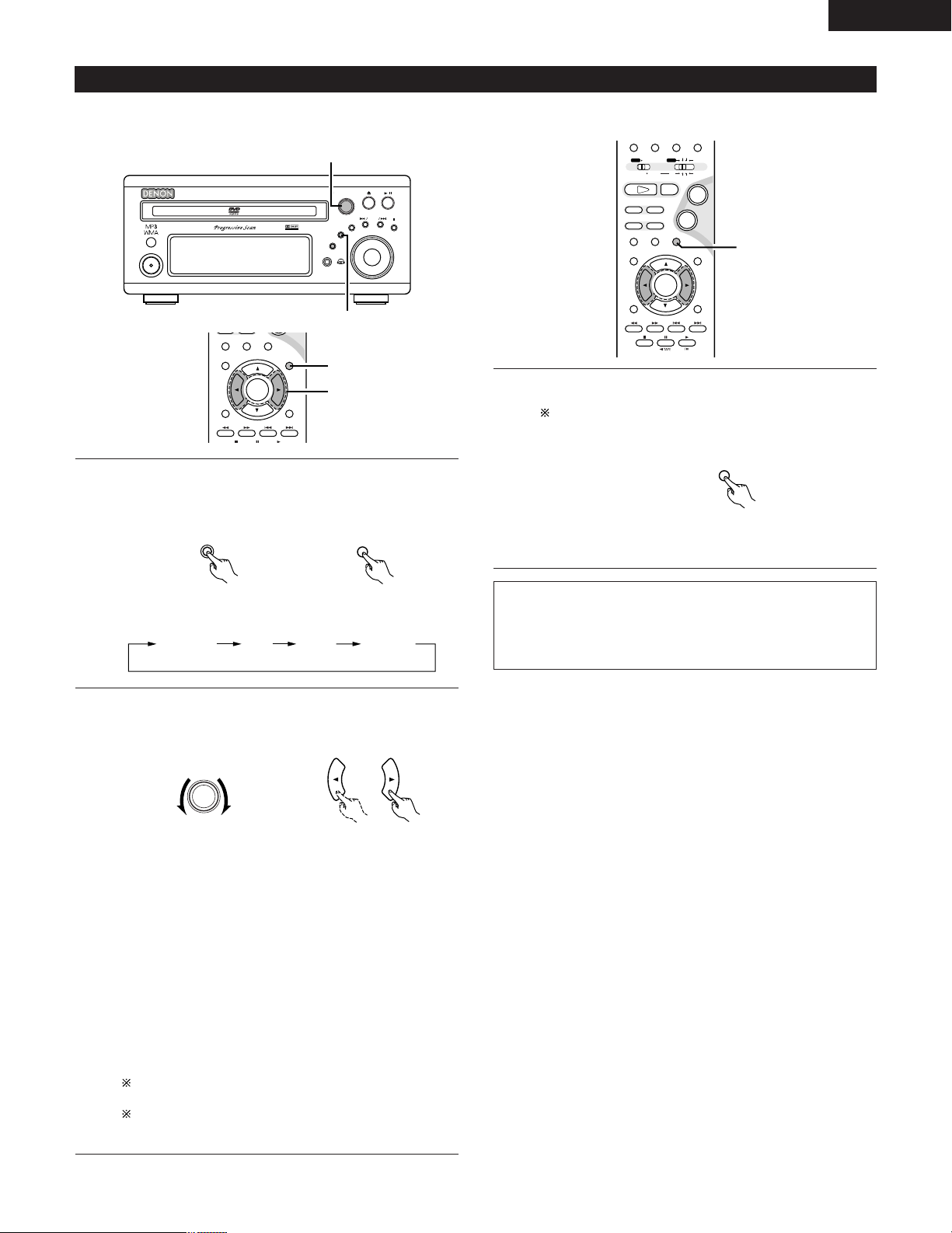
B
BAND
PHONES
VOLUME
ON / STANDBY
DVD SURROUND RECEIVER ADV-M71
TONE/SDB
FUNCTION
MENU/SET
+
-
SURROUND/ SELECT
PUSH - PARAM.
VIRTUAL SPEAKER
2
1
3
STATUS
RETURN
SETUP TONE/SDB
ENTER
MUTING
DISPLAY MENU
TOP MENU
SURROUND
PARAMETER
CH SELECT
-
+
VCR CH
1
2
A / V
3
STATUS
RETURN
ANGLE AUDIO
SUB TITLE
SETUP TONE/SDB
FUNCTIONSURROUNDINPUT MODETEST TONE
DVD
ENTER
MUTING
DISPLAY MENU
TOP MENU
SYSTEM MD
CDR TAPE
TUNER TV / VCR
SURROUND
PARAMETER
CH SELECT
-
+
VCR CH
IN/SURR.
IN/SURR.
DVD
9
8
21
76
+
-
1
After starting playback
TONE/ SDB
TONE/ SDB
MUTING
DEFEAT SDB
(ON/OFF)
BASS TREBLE
SURROUND/ SELECT
PUSH - PARAM.
ENGLISH
[1] Adjusting the sound quality (TONE/SDB)
The TONE/SDB function will not work in the direct mode.
Press the TONE/SDB button.
• The tone switches as follows each time the TONE/SDB
1
button is pressed.
[2] Turning the sound off temporarily (MUTING)
Use this to turn off the audio output temporarily.
Press the MUTING button.
1
Cancelling MUTING mode.
Press the MUTING button again.
Remote control unit
With the name of the volume to be adjusted selected, turn
the SURROUND/SELECT knob or cursor button ( 0, 1 ) to
2
adjust the level.
DEFEAT
• The signals do not pass through the SDB, bass and treble
adjustment circuits, providing higher quality sound.
SDB
• Either turn the FUNCTION / SELECT dial or use the (
1 ) cursor buttons to select “ON” or “OFF”.
BASS, TREBLE
• To increase the bass or treble: Turn the control clockwise or
press the cursor button. (The bass or treble sound can be
increased to up to +10 dB in steps of 2 dB.)
• To decrease the bass or treble: Turn the control clockwise
or press the cursor button. (The bass or treble sound can be
decreased to up to –10 dB in steps of 2 dB.)
Main unit Remote control unit
Main unit Remote control unit
0,
When TONE/SDB is displayed, the item can be switched
using the •and ª buttons on the remote control unit.
If no operation is performed within 4 seconds, the display
switches back to what was previously displayed.
NOTES:
• The mute mode is canceled when the main unit’s main volume
control or one of the main volume control buttons on the remote
control unit is operated.
• The setting is canceled if the set’s power is turned off.
45
Page 46
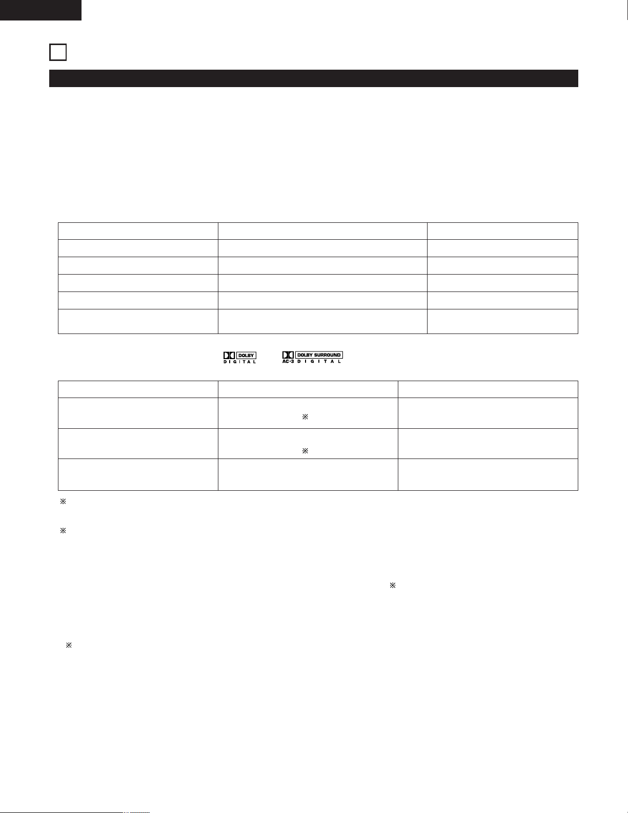
ENGLISH
13
DOLBY / DTS SURROUND
Surround
This unit is equipped with a digital signal processing circuit that lets you play program sources in the surround mode to achieve the same sense
of presence as in a movie theater.
Dolby Surround
(1) Dolby Digital (Dolby Surround AC-3)
Dolby Digital is the multi-channel digital signal format developed by Dolby Laboratories.
Dolby Digital consists of up to “5.1” channels - front left, front right, center, surround left, surround right, and an additional channel exclusively
reserved for additional deep bass sound effects (the Low Frequency Effects – LFE – channel, also called the “.1” channel, containing bass
frequencies of up to 120 Hz).
Unlike the analog Dolby Pro Logic format, Dolby Digital’s main channels can all contain full range sound information, from the lowest bass, up
to the highest frequencies – 22 kHz. The signals within each channel are distinct from the others, allowing pinpoint sound imaging, and Dolby
Digital offers tremendous dynamic range from the most powerful sound effects to the quietest, softest sounds, free from noise and distortion.
2 Dolby Digital and Dolby Pro Logic
Comparison of home surround systems
Dolby Digital
Dolby Pro Logic
No. recorded channels (elements)
No. playback channels
Playback channels (max.)
Audio processing
High frequency playback limit of surround
channel
2 Dolby Digital compatible media and playback methods
Digital discrete processing Dolby Digital (AC-3) encoding/decoding
5.1 ch
5.1 ch
L, R, C, SL, SR, SW
20 kHz
L, R, C, S (SW - recommended)
Analog matrix processing Dolby Surround
2 ch
4 ch
7 kHz
Marks indicating Dolby Digital compatibility: and .
The following are general examples. Also refer to the player’s operating instructions.
Media
LD (VDP)
DVD
Others
(satellite broadcasts, CATV, etc.)
Dolby Digital output jacks
Coaxial Dolby Digital RF output jack
1
Optical or coaxial digital output
(same as for PCM)
2
Optical or coaxial digital output
(same as for PCM)
Playback method (reference page)
Set the input mode to “AUTO”.
(Page 43, 44)
Set the input mode to “AUTO”.
(Page 43, 44)
Set the input mode to “AUTO”.
(Page 43, 44)
1 Use a commercially available adapter to connect Dolby Digital RF (AC-3RF) output signals to the digital input terminals. (Refer to the
adapter’s operating instructions.)
Please refer to the instruction manual of the adapter when making connection.
2 To play in Dolby Digital Surround on the ADV-M71, set “DVD SUTUP” – “AUDIO SETUP” – “DIGITAL OUT” to “Normal” in the setup.
(The factory default is “Normal”.)
(2) Dolby Pro Logic II
• Dolby Pro Logic II is a new multi-channel playback format developed by Dolby Laboratories using feedback logic steering technology and
offering improvements over conventional Dolby Pro Logic circuits.
• Dolby Pro Logic II can be used to decode not only sources recorded in Dolby Surround ( ) but also regular stereo sources into five channels
(front left, front right, center, surround left and surround right) to achieve surround sound.
• Whereas with conventional Dolby Pro Logic the surround channel playback frequency band was limited, Dolby Pro Logic II offers a wider
band range (20 Hz to 20 kHz or greater). In addition, the surround channels were monaural (the surround left and right channels were the
same) with previous Dolby Pro Logic, but Dolby Pro Logic II they are played as stereo signals.
•
Various parameters can be set according to the type of source and the contents, so it is possible to achieve optimum decoding (see page 59).
Sources recorded in Dolby Surround
These are sources in which three or more channels of surround have been recorded as two channels of signals using Dolby Surround
encoding technology.
Dolby Surround is used for the sound tracks of movies recorded on DVDs, LDs and video cassettes to be played on stereo VCRs, as well
as for the stereo broadcast signals of FM radio, TV, satellite broadcasts and cable TV.
Decoding these signals with Dolby Pro Logic makes it possible to achieve multi-channel surround playback. The signals can also be played
on ordinary stereo equipment, in which case they provide normal stereo sound.
There are two types of DVD Dolby surround recording signals.
q 2-channel PCM stereo signals
w 2-channel Dolby Digital signals
Regardless of the signal being played, when the 2-channel decode mode is set to the “Pro Logic II” mode in the “AUTO DECODE” mode,
the surround mode is automatically set to “Dolby Pro Logic II”.
46
Page 47
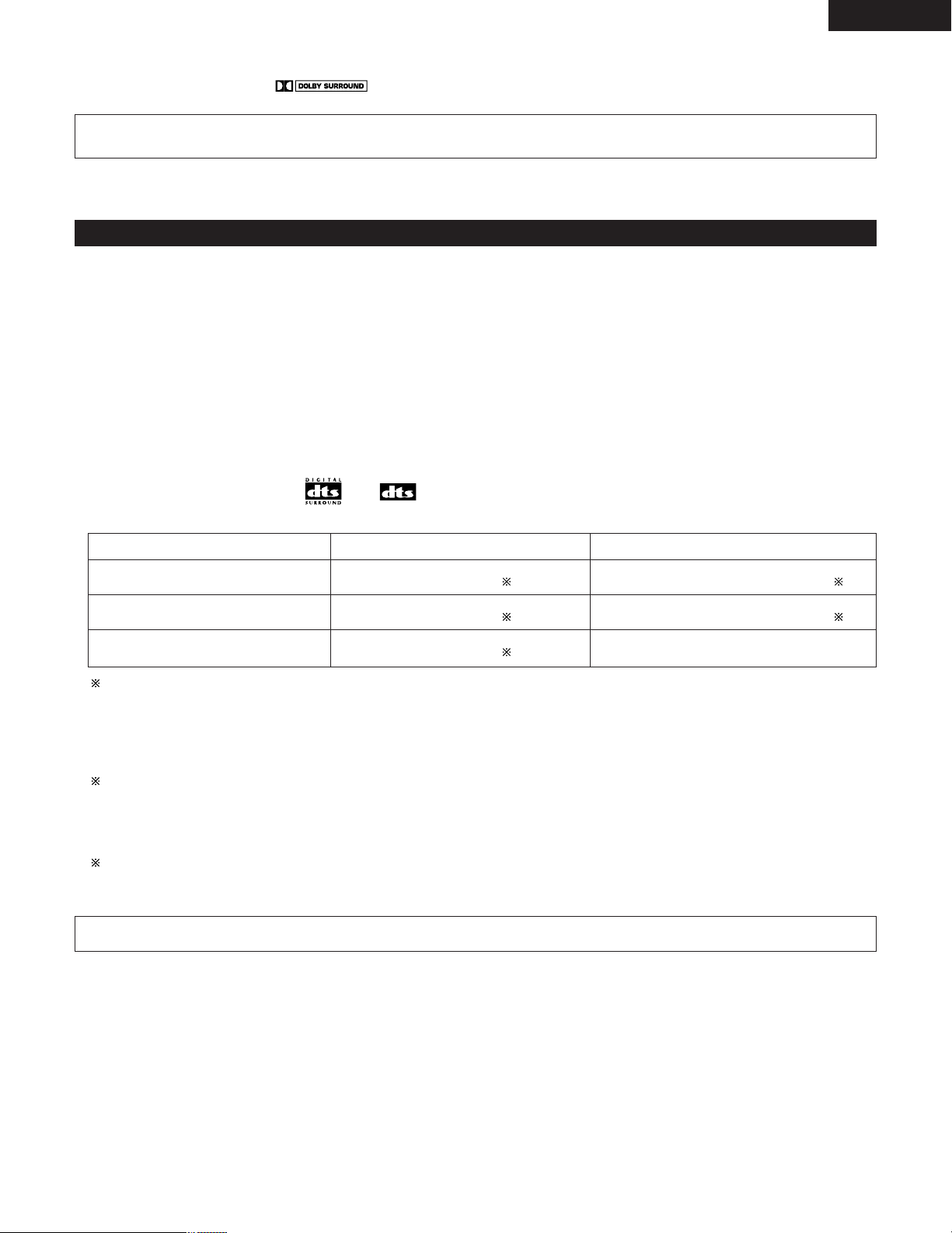
ENGLISH
2 Sources recorded in Dolby Surround are indicated with the logo mark shown below.
Dolby Surround support mark:
Manufactured under license from Dolby Laboratories.
“Dolby”, “Pro Logic” and the double-D symbol are trademarks of Dolby Laboratories.
DTS Digital Surround
Digital Theater Surround (also called simply DTS) is a multi-channel digital signal format developed by Digital Theater Systems.
DTS offers the same “5.1” playback channels as Dolby Digital (front left, front right and center, surround left and surround right) as well as the
stereo 2-channel mode. The signals for the different channels are fully independent, eliminating the risk of deterioration of sound quality due to
interference between signals, crosstalk, etc.
DTS features a relatively higher bit rate as compared to Dolby Digital (1234 kbps for CDs and LDs, 1536 kbps for DVDs) so it operates with a
relatively low compression rate. Because of this the amount of data is great, and when DTS playback is used in movie theaters, a separate CDROM synchronized with the film is played.
With LDs and DVDs, there is of course no need for an extra disc; the pictures and sound can be recorded simultaneously on the same disc, so
the discs can be handled in the same way as discs with other formats.
Other media include CDs recorded in DTS. These are the same discs as conventional CDs (recorded in 2 channels) but include 5.1 channel
surround signals. They do not include images, but they do permit surround playback on the ADV-M71 and on CD players.DTS surround track
playback offers the same intricate, grand sound as in a movie theater, right in your own listening room.
2 DTS compatible media and playback methods
Marks indicating DTS compatibility: and .
The following are general examples. Also refer to the player’s operating instructions.
Media
CD
LD (VDP)
DVD
DTS Digital output jacks
Optical or coaxial digital output
(same as for PCM) 2
Optical or coaxial digital output
(same as for PCM) 2
Optical or coaxial digital output
(same as for PCM) 3
Playback method (reference page)
Set the input mode to “AUTO” or “DTS” (page 43, 44).
Never set the mode to “ANALOG” or “PCM”. 1
Set the input mode to “AUTO” or “DTS” (page 43, 44).
Never set the mode to “ANALOG” or “PCM”. 1
Set the input mode to “AUTO” or “DTS” (page 43, 44).
1 DTS signals are recorded in the same way on CDs and LDs as PCM signals. Because of this, the un-decoded DTS signals are output as
random “hissy” noise from the CD or LD player’s analog outputs. If this noise is played with the amplifier set at a very high volume, it
may possibly cause damage to the speakers. To avoid this, be sure to switch the input mode to “AUTO” or “DTS” before playing CDs or
LDs recorded in DTS. Also, never switch the input mode to “ANALOG” or “PCM” during playback. The same is true when playing CDs
and LDs recorded in DTS on the ADV-M71 or on LD/DVD compatible players. With DVDs, the DTS signals are recorded with a special
recording method so there is no problem. For DVDs, the DTS signals are recorded in a special way so this problem does not occur.
2 The signals provided at the digital outputs of a CD or LD player may undergo some sort of internal signal processing (output level
adjustment, sampling frequency conversion, etc.). In this case the DTS-encoded signals may be processed erroneously, in which case they
cannot be decoded by this unit, or may only produce noise. Before playing DTS signals for the first time, turn down the master volume to
a low level, start playing the DTS disc, then check whether the DTS indicator on this unit (see page 44) lights before turning up the master
volume.
3 To play in DTS Digital Surround on the ADV-M71, set “DVD SETUP” — “AUDIO SETUP” — “DIGITAL OUT” to “Normal” in the setup.
(The factory default is “Normal”.)
“DTS” and “DTS Digital Surround” are registered trademarks of Digital Theater Systems, Inc.
47
Page 48
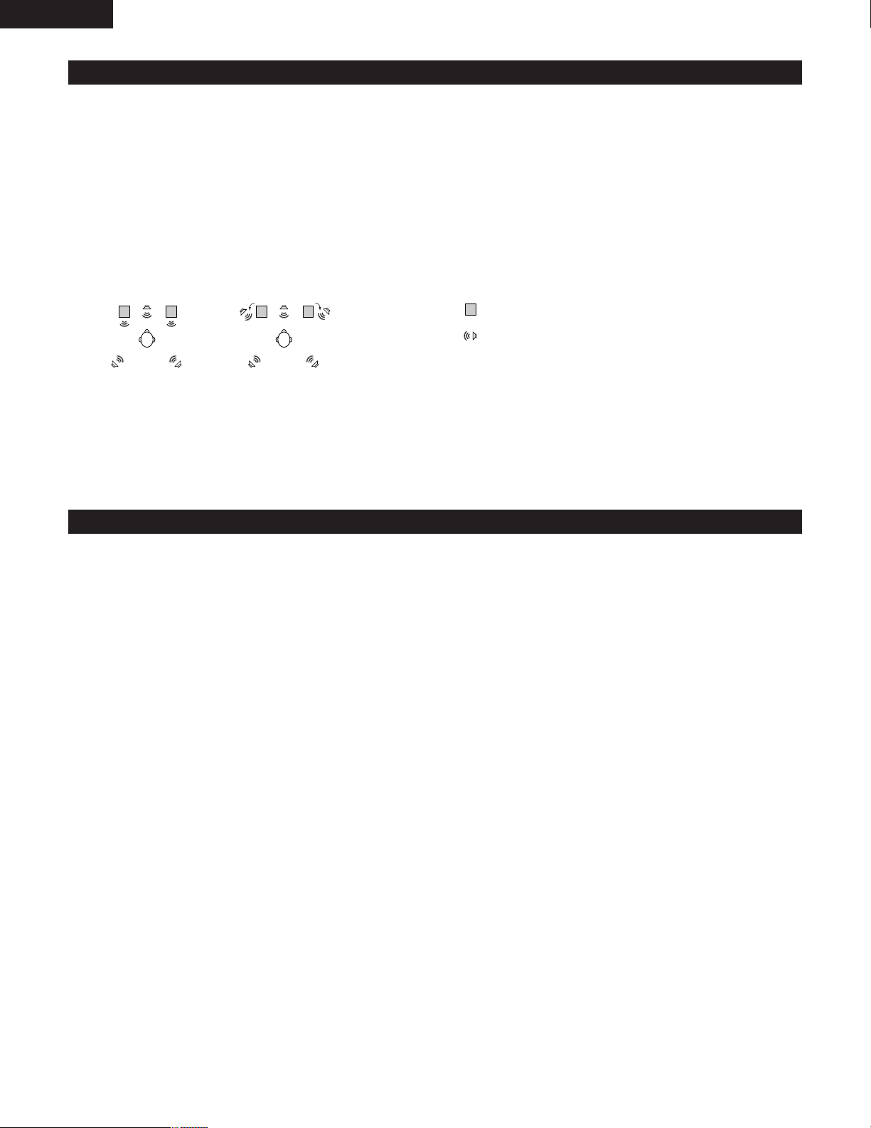
ENGLISH
Dolby Virtual Speaker
Dolby Virtual Speaker technology uses proprietary technology of Dolby Laboratories to create a virtual surround sound field using only two
speakers for the front channels, allowing the user to experience sound as if surround speakers were actually being used.
2 Features of Dolby Virtual Speaker sound
B Accurate surround sound field positioning
The virtual surround speakers are positioned at 105° to the left and 105° to the right.
B Multi-channel programs played according to the producer’s intentions
The sound of the different channels is played in the position set upon mixing. For example, sound set at the rear left is heard from the rear
left.
B Stereo programs played in surround
The Dolby Pro Logic II circuit is used together with the Dolby Virtual Speaker circuitry to create a rich virtual surround sound field with stereo
programs as well.
B Selecting the listening mode
Two listening modes are provided: Reference and Wide.
: 2 front channels
: Virtual sound field created with the Dolby
Virtual Speaker mode
Reference mode Wide mode
With the ADV-M71, playback in the Dolby Virtual Speaker mode is possible with other speaker configurations as well.
• 3 speakers (2 front channels + center) : Reference/Wide modes
• 4 speakers (2 front channels + 2 surround channels) : Wide mode
• 5 speakers (2 front channels + center + 2 surround channels) : Wide mode
Dolby Headphone
Dolby Headphone is a 3D sound technology developed jointly by Dolby Laboratories and Lake Technology of Australia achieving surround sound
with regular headphones.
Normally when using headphones all the sounds are sounded in the head, making it uncomfortable to listen with headphones for long periods of
time. Dolby Headphone simulates speaker playback in a room and positions the sound sources to the front or the sides, outside of the head,
achieving a powerful sound similar to that of a movie theater or home theater. This technology is aimed mainly at multi-channel audio or video
equipment including Dolby Digital or Dolby Pro Logic Surround decoding functions and operates inside a high performance digital signal processing
chip (DSP).
The Dolby Headphone mode can be used not only with multi-channel sources but also with stereo programs.
48
Page 49
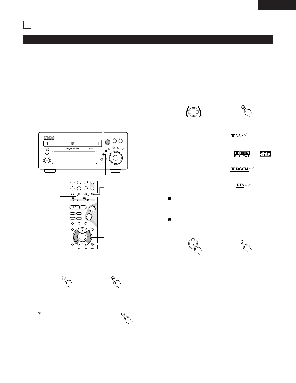
ENGLISH
B
BAND
PHONES
VOLUME
ON / STANDBY
DVD SURROUND RECEIVER ADV-M71
TONE/SDB
FUNCTION
MENU/SET
+
-
SURROUND/ SELECT
PUSH - PARAM.
VIRTUAL SPEAKER
1
3,5,6
+
-
A / V
3
STATUS
SETUP TONE/SDB
FUNCTIONSURROUNDINPUT MODETEST TONE
DVD
CH
987
0
/
10
CALL
ENTER
MUTING
+
10
SYSTEM MD
CDR TAPE
TUNER TV / VCR
SURROUND
PARAMETER
CH SELECT
VIRTUALDIRECT STEREO
-
+
VCR CH
IN/SURR.
IN/SURR.
DVD
9
8
21
76
+
-
2
3
1
6
5
FUNCTION
FUNCTION
INPUT MODE
SURROUND/ SELECT
PUSH - PARAM.
SURROUND
SURROUND/ SELECT
PUSH - PARAM.
SURROUND
PARAMETER
14
SURROUND PLAYBACK
(1)
Playing in the Dolby Virtual Speaker mode
• The Dolby Virtual Speaker mode is a mode using 3D sound technology from Dolby Laboratories to achieve multi-channel surround sound using
only two speakers for the front channels.
• With two speakers for the front channels, one of two modes can be selected: Reference or Wide.
• The Dolby Virtual Speaker mode can be used not only with Dolby Digital and DTS multi-channel sources but also with 2-channel sources. With
2-channel sources, one of two 2-channel modes can be selected: Virtual 1 (Dolby Pro Logic II Cinema) and Virtual 2 (Dolby Pro Logic).
• With a multi-channel speaker configuration (for example 5.1 channels), the Dolby Virtual Speaker mode provides different effects according to
the speaker configuration.
[1] Playing Dolby Digital and DTS surround sound (with digital
inputs only)
B Applicable sources
• Digital input (LINE-1 and D.AUX functions, including DVD
playback discs)
Dolby Digital multi-channel sources
DTS sources
Set the surround mode to “DOLBY VIRTUAL SPEAKER”.
3
Main unit Remote control unit
• In the Dolby Virtual Speaker
mode, this indicator lights.
Lit
Select the digital input function (DVD or LINE-1 or D.AUX
digital input).
1
Play a program source including the or
4
mark.
• The Dolby Digital indicator lights
when playing Dolby Digital
sources.
• The DTS indicator lights when
playing DTS sources.
This switches automatically according to the format of the
playback source.
Display the surround parameters for that source.
5
When the function is set to DVD, this is displayed on the
screen as well.
Main unit Remote control unit
Lit
Lit
2
Main unit Remote control unit
Set the input mode to “AUTO”.
DTS sources can also be played with
the input mode set to “DTS”.
Remote control unit
49
Page 50
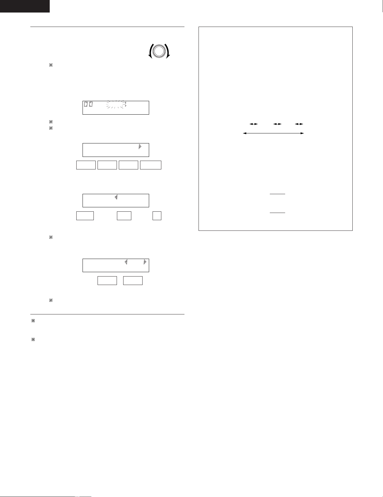
ENGLISH
SURROUND/ SELECT
PUSH - PARAM.
VS REF WIDE
D.COMP. OFF
LFE 0dB
DEFAULT Y/N
Select and set the surround
parameters.
6
(On the remote control unit, use the
0, 1 cursor buttons to set the
parameters.)
If nothing is done for 6 seconds
from when the parameter is
displayed, the normal display
reappears.
B Setting the DOLBY VS mode
The selected mode flashes.
The mode is not displayed if it cannot be selected.
B D.COMP. setting
OFF LOW MID HI
B Setting the LFE level
-10 -5 0
,/
... ...
,/
Main unit
Surround parameters (1)
DOLBY VS (Dolby Virtual Speaker mode)
• REF (Reference mode)
This is the standard mode.
• WIDE (Wide mode)
This mode expands the front channel sound field.
D.COMP. (Dynamic range compression)
• This parameter adjusts the dynamic range of the Dolby
Digital sound. When listening with the volume turned
relatively low, at night for example, set this to the “HI” side
to lower the peak of the sound and amplify the quieter
sounds, narrowing the dynamic range and making the sound
easier to listen to. Set to “OFF” to turn this function off.
OFF LOW MID HI
Wide
LFE (Low Frequency Effect):
• Program source and adjustment range
1. Dolby Digital : –10 dB to 0 dB
2. DTS Surround : –10 dB to 0 dB
• When Dolby Digital encoded software is played, it is
recommended that the LFE LEVEL be set to 0 dB for correct
Dolby Digital playback.
• When DTS encoded movie software is played, it is
recommended that the LFE LEVEL be set to 0 dB for correct
DTS playback.
• When DTS encoded music software is played, it is
recommended that the LFE LEVEL be set to –10 dB for
correct DTS playback.
Dynamic range
Narrow
The LFE level can be adjusted in steps of 1 dB between 10 dB and 0 dB.
B DEFAULT setting
YES NO
,/
When “YES” is selected, the settings are restored to the
factory defaults.
When the surround parameters are displayed, use the •and ª
cursor buttons on the remote control unit to switch to previous or
following items.
Once the surround parameters have been set, stop operating the
buttons. After several seconds, the normal display reappears and
the settings are automatically entered.
50
Page 51
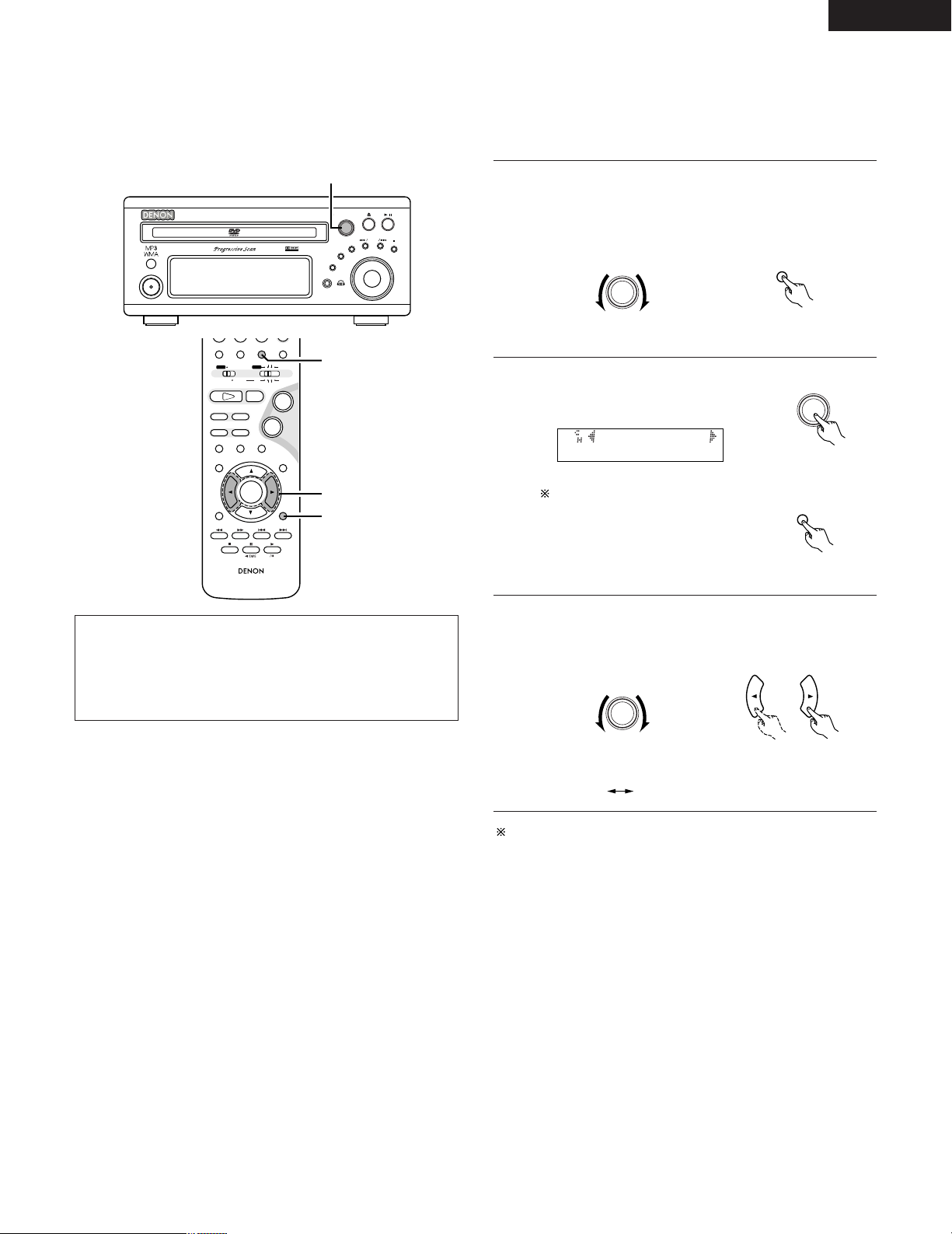
ENGLISH
B
BAND
PHONES
VOLUME
ON / STANDBY
DVD SURROUND RECEIVER ADV-M71
TONE/SDB
FUNCTION
MENU/SET
+
-
SURROUND/ SELECT
PUSH - PARAM.
VIRTUAL SPEAKER
1,2,3
RC-936
A / V
3
STATUS
RETURN
ANGLE AUDIO
SUB TITLE
SETUP TONE/SDB
FUNCTIONSURROUNDINPUT MODETEST TONE
DVD
ENTER
MUTING
DISPLAY MENU
TOP MENU
SYSTEM MD
CDR TAPE
TUNER TV / VCR
SURROUND
PARAMETER
CH SELECT
-
+
VCR CH
IN/SURR.
IN/SURR.
DVD
9
8
21
76
+
-
1
3
2
SURROUND/ SELECT
PUSH - PARAM.
SURROUND
SURROUND/ SELECT
PUSH - PARAM.
2 VIRTUAL 1
SURROUND
PARAMETER
SURROUND/ SELECT
PUSH - PARAM.
VIRTUAL 1 VIRTUAL 2
[2] 2-channel mode settings
• When 2-channel signals are input, one of two playback modes can be selected and set according to the 2-channel mode setting, Virtual 1 or
Virtual 2. (The Virtual 1 mode is set by factory default.)
Virtual 1 : 2-channel sources are played in virtual surround using Dolby Pro Logic II Cinema processing.
Virtual 1 : 2-channel sources are played in virtual surround using Dolby Pro Logic processing.
Set the surround mode to “DOLBY VIRTUAL SPEAKER”
(“DOLBY VS”).
1
• The normal display reappears after the surround mode is
displayed.
Main unit Remote control unit
Press the SURROUND PARAMETER
2
button and select the 2-channel
mode.
Main unit
NOTES:
• The 2-channel mode cannot be set when Dolby Digital or DTS
5.1-channel signals.
• The 2-channel mode is set and stored in the memory individually
for the different functions.
This can be selected if there is no
digital input signal, if the digital
input is a PCM or Dolby Digital 2channel signal and if the input is
analog.
Remote control unit
Turn the SURROUND/SELECT control on the main unit or use
3
the
1 cursor buttons on the remote control unit to
0
and
select the desired 2-channel mode.
Main unit Remote control unit
Once the surround parameters have been set, stop operating the
buttons. After several seconds, the normal display reappears and
the settings are automatically entered
51
Page 52
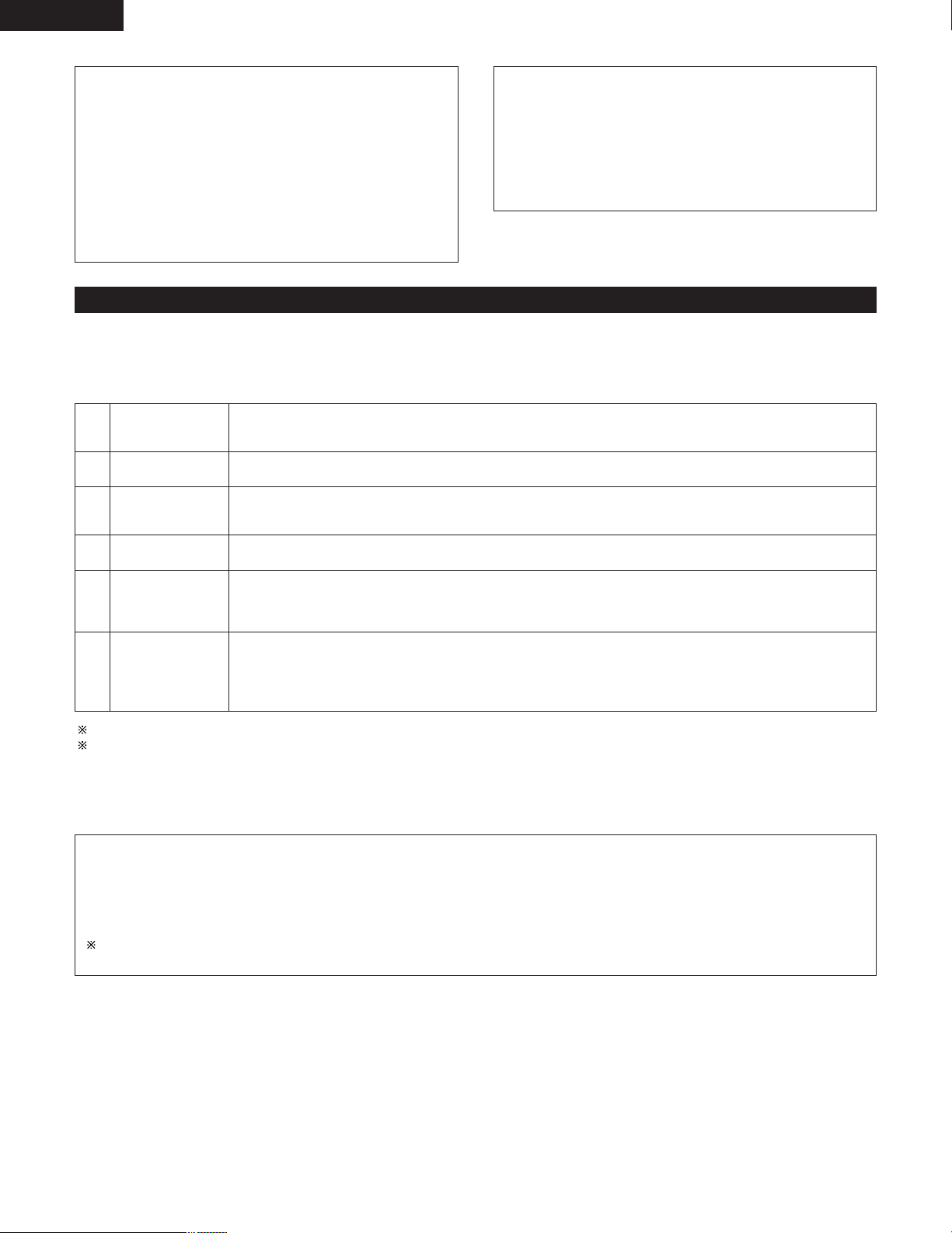
ENGLISH
Surround parameters (2)
1. VIRTUAL1 (Virtual 1 mode)
In this mode, 2-channel sources are played with Dolby Pro Logic
II Cinema processing. This mode is suited for playing movie
sources recorded in Dolby Surround and regular stereo sources.
2. VIRTUAL2 (Virtual 2 mode)
In this mode, 2-channel sources are played with Dolby Pro Logic
processing. This mode is compatible with regular Dolby Pro
Logic playback. With it, the recorded playback image of sources
recorded in Dolby Surround is recreated faithfully.
(2)
Playing in the DENON original surround modes
• This unit is equipped with a high performance DSP (Digital Signal Processor) which uses digital signal processing to synthetically recreate the
sound field. One of 6 preset surround modes can be selected according to the program source and the parameters can be adjusted according
to the conditions in the listening room to achieve a more realistic, powerful sound. These surround modes can also be used for program sources
not recorded in Dolby Surround Pro Logic or Dolby Digital.
*
1
*
2
*
3
MONO MOVIE
(NOTE 1)
ROCK ARENA
JAZZ CLUB
Select this when watching monaural movies for a greater sense of expansion.
Use this mode to achieve the feeling of a live concert in an arena with reflected sounds coming from all directions.
This mode creates the sound field of a live house with a low ceiling and hard walls. This mode gives jazz a very
vivid realism.
NOTE:
• If noise is generated for interactive and other high bit rate
sources when playing DVDs or D.AUX digital input signals in the
Dolby Virtual Speaker mode, set “LINE-1/LINE-2 REC OUT”
under “[5] Function settings” at “SYSTEM SETUP” on pages 37
and 38 to “Off”.
(When this is done, analog recording in the Dolby Virtual Speaker
mode is not possible.)
*
VIDEO GAME
4
*
MATRIX
5
*
5CH STEREO
6
Surround modes indicated “*” can be selected when the speaker setting is set to 5.1 channels.
Depending on the source being played, the effect may not be very strong.
In such cases, try other surround modes without paying too much attention to their names and choose the one you feel is best.
NOTE 1: When playing sources recorded in monaural, the sound is one-sided if only one channel (left or right) is input, so input signals to both
channels.
Personal Memory Plus
This set is equipped with a personal memorize function that automatically memorizes the surround modes and input modes selected for the
input different sources. When the input source is switched, the modes set for that source last time it was used are automatically recalled.
• Settings automatically stored in the memory for the individual input functions using the Personal Memory Plus function:
q Surround mode (including 2-channel decode mode and Dolby Pro Logic II mode settings)
w Input mode selection function
The surround parameters, TONE/SDB control settings and playback level balance for the different output channels are memorized for each
surround mode.
Use this to enjoy video game sources.
Select this to emphasize the sense of expansion for music sources recorded in stereo. Signals consisting of the
difference component of the input signals (the component that provides the sense of expansion) processed for
delay are output from the surround channel.
In this mode, the signals of the front left channel are output from the left surround channel, the signals of the front
right channel are output from the right surround channel, and the same (in-phase) component of the left and right
channels is output from the center channel. This mode provides all speaker surround sound, but without directional
steering effects, and works with any stereo program source.
52
Page 53
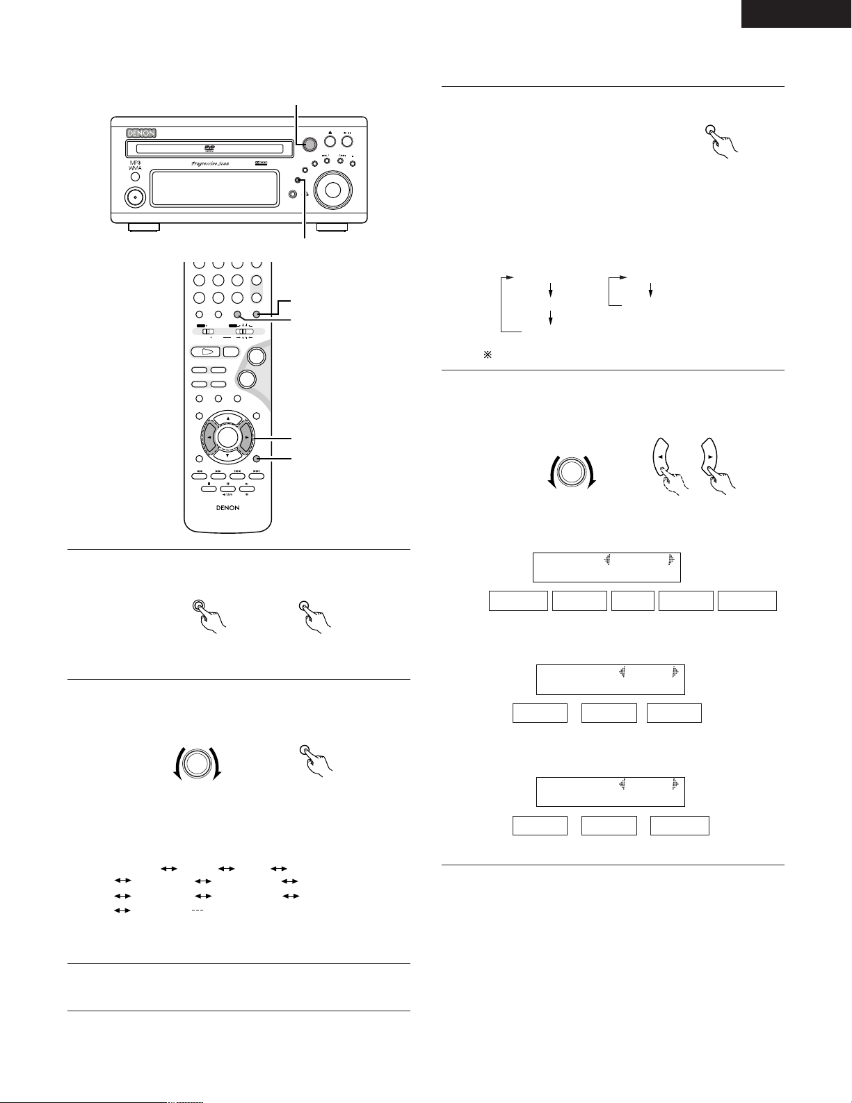
[1] DSP Surround simulation
B
BAND
PHONES
VOLUME
ON / STANDBY
DVD SURROUND RECEIVER ADV-M71
TONE/SDB
FUNCTION
MENU/SET
+
-
SURROUND/ SELECT
PUSH - PARAM.
VIRTUAL SPEAKER
2,4,5
1
+
-
-
RC-936
A / V
3
STATUS
RETURN
ANGLE AUDIO
SUB TITLE
SETUP TONE/SDB
FUNCTIONSURROUNDINPUT MODETEST TONE
DVD
TUNER
CH
654
987
0
/
10
CALL
ENTER
MUTING
+
10
DISPLAY MENU
TOP MENU
SYSTEM MD
CDR TAPE
TUNER TV / VCR
SURROUND
PARAMETER
CH SELECT
AUTO DECODE
VIRTUALDIRECT
5CH STEREO
STEREO
-
+
VCR CH
IN/SURR.
IN/SURR.
DVD
9
8
21
76
+
-
1
2
5
4
FUNCTION
FUNCTION
SURROUND/ SELECT
PUSH - PARAM.
SURROUND
DOLBY VS STEREO *AUTO DECODE
*5CH STEREO *MONO MOVIE
ROCK ARENA
DIRECT
JAZZ CLUB
DOLBY VS
VIDEO GAME *MATRIX
SURROUND
PARAMETER
ROOM SIZE
EFFECT
DEFAULT
DELAY
DEFAULT
MONO MOVIE
ROCK ARENA
JAZZ CLUB
VIDEO GAME
MATRIX
SURROUND/ SELECT
PUSH - PARAM.
To enter the surround parameter
4
setting mode, press the SURROUND
mode.
• The surround parameter switches
in the following order each time the
SURROUND button is pressed for
the different surround modes.
Remote control unit
There is no 5-channel stereo mode.
Display the parameter you want to adjust.
5
• Use the cursor buttons (•, ª) to select the surround
parameter.
ENGLISH
Select the input source.
1
Main unit
Select the surround mode for the input channel.
2
Main unit
• The surround mode switches in the following order each
time the SURROUND MODE button is pressed:
• The modes marked “*” can be selected when “5.1channel surround” is selected in the quick system setup.
3
Play a program source.
• Refer to instruction manual for handling.
Remote control unit
Remote control unit
Main unit
• ROOM SIZE setting
R.SIZE MED
SMALL
MED-S MED MED-L LARGE
,/
• EFFECT LEVEL setting
EFECT 10
1 10 15
,/
• DELAY TIME setting
DELAY 30ms
0ms 30ms
,/
Remote control unit
110ms
53
Page 54
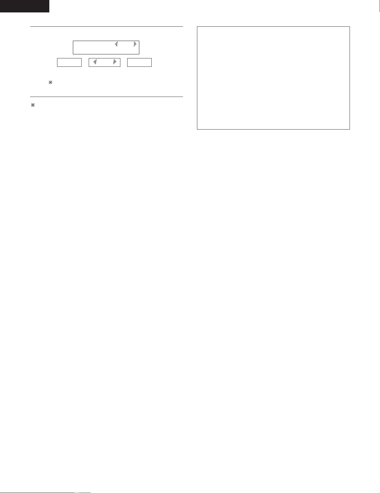
ENGLISH
DEFAULT Y/N
• DEFAULT setting
5
YES NO
When “YES” is selected, the settings are reset to their
factory default values.
Stop operating buttons once the surround parameter settings have
been completed. After several seconds the normal display
reappears and the settings are automatically set.
Y/N
,/
Surround parameters (3)
ROOM SIZE:
• This sets the size of the sound field.
There are five settings: “SMALL”, “MED-S” (mediumsmall), “MED”, “MED-L” (medium-large) and “LARGE”.
“SMALL” recreates a small sound field, “LARGE” a large
sound field.
EFFECT LEVEL:
• This sets the strength of the surround effect.
The level can be set in 15 steps from 1 to 15. Lower the
level if the sound seems distorted.
DELAY TIME:
• In the MATRIX mode only, the delay time can be set within
the range of 0 to 110 ms.
54
Page 55
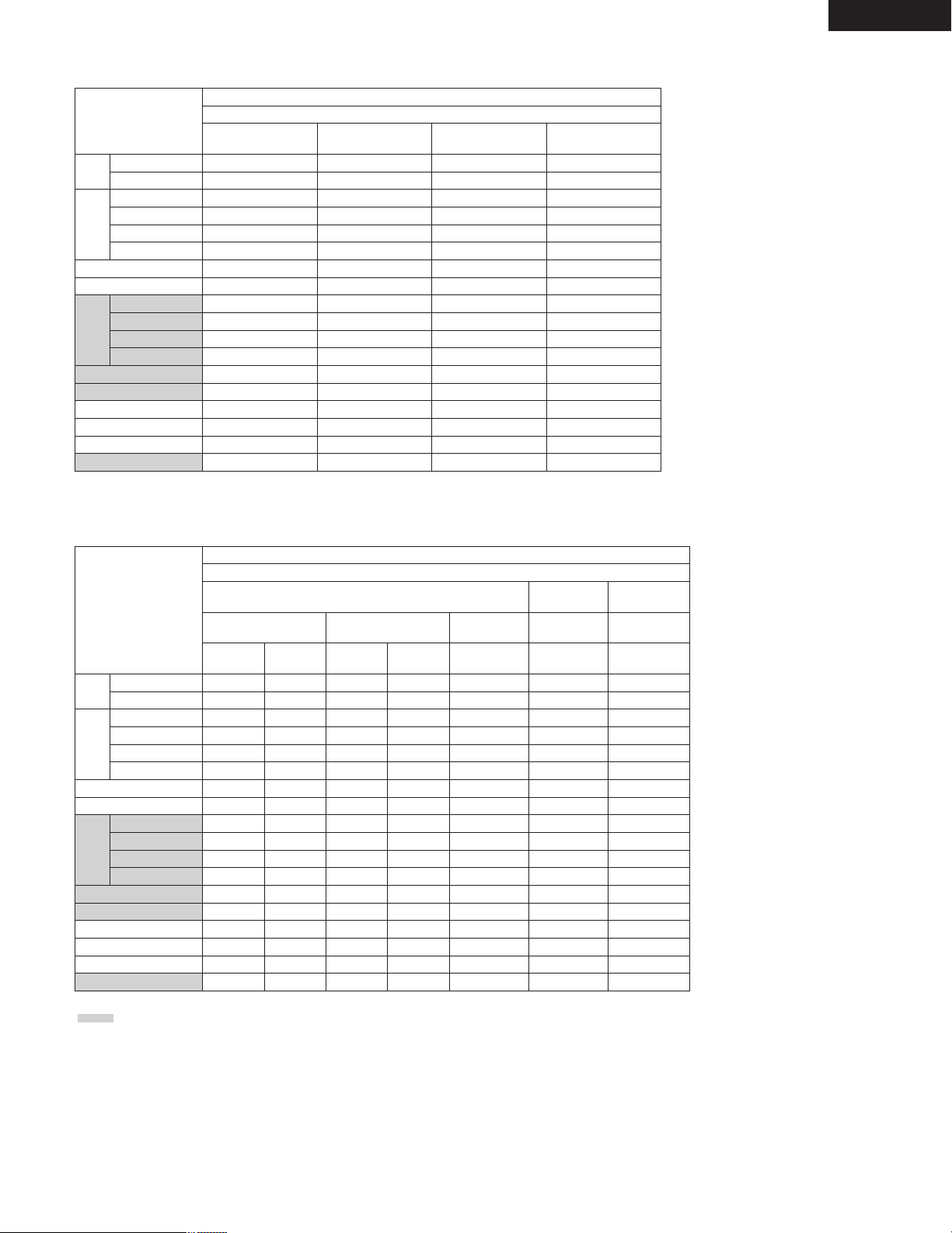
2 Table of Surround Mode Parameters (1)
Surround Mode
DVS: Dolby Virtual Speaker
DHP: Dolby Headphone
REFERENCE
DVS
WIDE
DH1
DH2
DHP
DH3
BYPASS
STEREO
DIRECT
DOLBY DIGITAL
DTS SURROUND
DOLBY PL II
AUTO
DECODE
AUTO STEREO
5CH STEREO
MONO MOVIE
ROCK ARENA
JAZZ CLUB
VIDEO GAME
MATRIX
C (H/P ONLY)
C (H/P ONLY)
C (H/P ONLY)
C (H/P ONLY)
Presence/absence of signals and controllability in the various modes
FRONT
L/R
C
C
C
C
C
C
C
C
C
C
C
C
C
C
CENTER
B
B
E
E
E
E
E
E
B
B
B
E
B
B
B
B
B
B
Channel output
SURROUND
L/R
E
B
E
E
E
E
E
E
B
B
B
E
B
B
B
B
B
B
ENGLISH
SUB-WOOFER
B
B
E
E
E
E
B
B
B
B
B
B
B
B
B
B
B
B
2 Table of Surround Mode Parameters (2)
Presence/absence of signals and controllability in the various modes
Playback signals and surround modes for the various input functions
Surround Mode
DVS: Dolby Virtual Speaker
DHP: Dolby Headphone
REFERENCE
DVS
WIDE
DH1
DH2
DHP
DH3
BYPASS
STEREO
DIRECT
DOLBY DIGITAL
DTS SURROUND
DOLBY PL II
AUTO
DECODE
AUTO STEREO
5CH STEREO
MONO MOVIE
ROCK ARENA
JAZZ CLUB
VIDEO GAME
MATRIX
B : Can be either present or absent, depending on speaker configuration setting.
: Only usable when center or surround speakers set to be used with the speaker configuration setting.
C : Signal present or controllable. D.MIX: Compatible with down-mixing.
: Can be selected with 2-channel decode mode. PL II: Compatible with PL II processing.
4
E : No signal or not controllable.
When playing Dolby Digital
signals
2-channel
4PL II
4PL II
4PL II
4PL II
4PL II
C
C
C
C
E
4PL II
4
C
C
C
C
C
C
DVD / D.AUX / MD / LINE1
When playing DTS signals
Multi-
channel
C D.MIX
C D.MIX
C D.MIX
2-channel
C
C
C
C
C
C
E
E
E
C
C
C
C
C
C
4PL II
4PL II
4PL II
4PL II
4PL II
C
C
C
E
E
4PL II
4
C
C
C
C
C
C
When playing
PCM signals
Multi-
channel
C
C
C
C
C
C D.MIX CCC
C D.MIX CCC
C D.MIX CCC
EE E E
CE E E
E
E
CC C C
CC C C
CC C C
CC C C
CC C C
CC C C
2-channel 2-channel 2-channel
4PL II 4PL II 4PL II
4PL II 4PL II 4PL II
4PL II 4PL II 4PL II
4PL II 4PL II 4PL II
4PL II 4PL II 4PL II
4PL II 4PL II 4PL II
(D.AUX / L2)
MD / LINE1
When playing
analog signals
44
TAPE / LINE2 /
When playing
analog signals
TUNER
E
55
Page 56
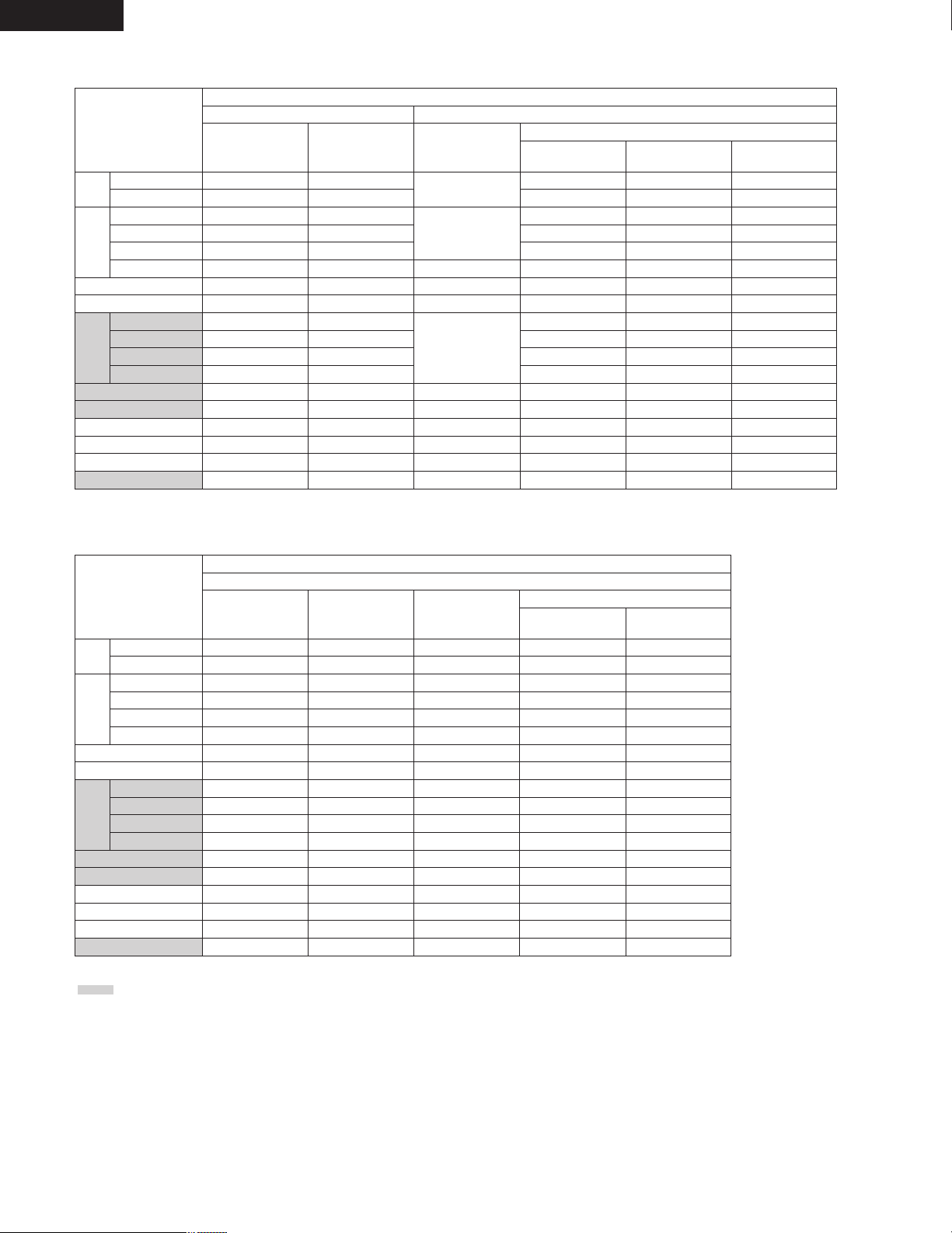
ENGLISH
2 Table of Surround Mode Parameters (3)
Surround Mode
DVS: Dolby Virtual Speaker
DHP: Dolby Headphone
REFERENCE
DVS
WIDE
DH1
DH2
DHP
DH3
BYPASS
STEREO
DIRECT
DOLBY DIGITAL
DTS SURROUND
DOLBY PL II
AUTO
DECODE
AUTO STEREO
5CH STEREO
MONO MOVIE
ROCK ARENA
JAZZ CLUB
VIDEO GAME
MATRIX
SDB
C (OFF)
C (OFF)
C (OFF)
C (OFF)
C (OFF)
C (OFF)
C (OFF)
E
C (OFF)
C (OFF)
C (OFF)
C (OFF)
C (OFF)
C (OFF)
C (OFF)
C (OFF)
C (OFF)
C (OFF)
Presence/absence of signals and controllability in the various modes
Surround parameter – default value indicated in (parentheses)
TONE
CONTROL
C (OFF)
C (OFF)
C (OFF)
C (OFF)
C (OFF)
C (OFF) E
C (OFF)
E
C (OFF)
C (OFF)
C (OFF)
C (OFF)
C (OFF)
C (OFF)
C (OFF)
C (OFF)
C (OFF)
C (OFF)
2ch
DECODE
MODE
C
(VIRTUAL1)
C *2
(CINEMA)
E
E
C *1
(AUTO
STEREO)
E
E
E
E
E
E
PANORAMA DIMENSION CENTER WIDTH
EEE
EEE
EEE
EEE
EEE
EEE
EEE
EEE
EEE
EEE
C (OFF) C (3) C (3)
EEE
EEE
EEE
EEE
EEE
EEE
EEE
Pro Logic II Music mode only
2 Table of Surround Mode Parameters (4)
Presence/absence of signals and controllability in the various modes
Surround Mode
DVS: Dolby Virtual Speaker
DHP: Dolby Headphone
REFERENCE
DVS
WIDE
DH1
DH2
DHP
DH3
BYPASS
STEREO
DIRECT
DOLBY DIGITAL
DTS SURROUND
DOLBY PL II
AUTO
DECODE
AUTO STEREO
5CH STEREO
MONO MOVIE
ROCK ARENA
JAZZ CLUB
VIDEO GAME
MATRIX
: Only usable when center or surround speakers set to be used with the speaker configuration setting.
C : Signal present or controllable.
E : No signal or not controllable.
*1 : Auto Stereo mode or Dolby PL II mode (Cinema, Music or Dolby PL mode) selectable.
*2 : Dolby PL II mode (Cinema, Music or Music 2 mode) selectable.
D.MIX: Compatible with down-mixing.
( ): Parameter’s default value
ROOM
SIZE
E
E
E
E
E
E
E
E
E
E
E
E
E
C (MEDIUM)
C (MEDIUM)
C (MEDIUM)
C (MEDIUM)
E
Surround parameter – default value indicated in (parentheses)
EFFECT
LEVEL
E
E
E
E
E
E
E
E
E
E
E
E
E
C (10)
C (10))
C (10)
C (10)
E
DELAY
TIME
C (30ms)
Dolby Digital/DTS signal
D. COMP. LFE
E
E
E
E
E
E
E
E
E
E
E
E
E
E
E
E
E
C (OFF) C (0dB)
C (OFF) C (0dB)
C (OFF) C (0dB)
C (OFF) C (0dB)
C (OFF) C (0dB)
C (OFF) C (0dB)
C (OFF) C (0dB)
C (OFF) C (0dB)
C (OFF) C (0dB)
C (OFF) C (0dB)
C (OFF) C (0dB)
EE
C (OFF) C (0dB)
C (OFF) C (0dB)
C (OFF) C (0dB)
C (OFF) C (0dB)
C (OFF) C (0dB)
C (OFF) C (0dB)
56
Page 57
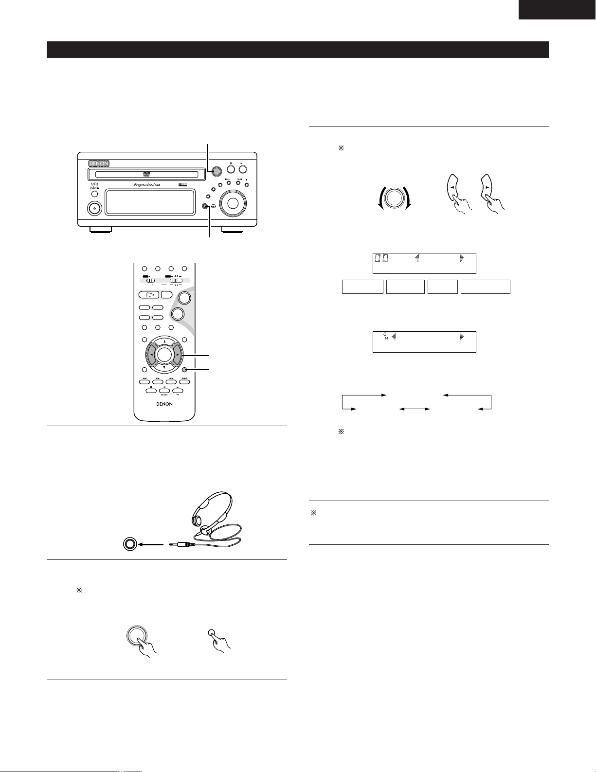
ENGLISH
B
BAND
PHONES
VOLUME
ON / STANDBY
DVD SURROUND RECEIVER ADV-M71
TONE/SDB
FUNCTION
MENU/SET
+
-
SURROUND/ SELECT
PUSH - PARAM.
VIRTUAL SPEAKER
2,3
1
RC-936
A / V
3
STATUS
RETURN
ANGLE AUDIO
SUB TITLE
SETUP TONE/SDB
FUNCTIONSURROUNDINPUT MODETEST TONE
DVD
ENTER
MUTING
DISPLAY MENU
TOP MENU
SYSTEM MD
CDR TAPE
TUNER TV / VCR
SURROUND
PARAMETER
CH SELECT
-
+
VCR CH
IN/SURR.
IN/SURR.
DVD
9
8
21
76
+
-
3
2
PHONES
SURROUND/ SELECT
PUSH - PARAM.
SURROUND
PARAMETER
SURROUND/ SELECT
PUSH - PARAM.
CINEMA
MUSIC2
MUSIC1
HDH1
2 CINEMA
(3)
Playback using the Dolby Headphone mode
• The ADV-M71 is equipped with the Dolby Headphone mode, a technology developed jointly by Dolby Laboratories and Lake Technology for
achieving 3D sound over regular headphones.
• The Dolby Headphone mode is set when headphones are connected to the ADV-M71’s headphones jack.
• There are actually four Dolby Headphone modes creating different sound field effects: DH1, DH2, DH3 and Bypass (normal stereo playback).
• The Dolby Headphone mode is compatible with Dolby Digital and DTS multi-channel sources. With 2-channel sources, playback in the Cinema,
Music 1 and Music 2 modes can be selected with the 2-channel mode setting.
Set the various surround parameters.
3
If nothing is done for 6 seconds from when the parameter
is displayed, the normal display reappears.
Main unit Remote control unit
• Dolby H mode setting
Connect headphones (sold separately) to the headphones
1
jack.
• When headphones are plugged in, the output to the
speakers is automatically turned off and no sound is
produced from the speakers.
DH1
DH2 DH3 BYPASS
,/
• 2-channel mode setting
• The mode switches as shown below each time a button is
operated.
Can be selected when there is no signal or when playing a
2-channel source.
There are also the same parameters as those described under
“(2) Playing in the Dolby Virtual Speaker mode”, namely:
B D.COMP. setting
B LFE level setting
B DEFAULT setting
When the surround parameters are displayed, use the • and ª
cursor buttons on the remote control unit to switch to previous or
following items.
Press the surround parameter button and display the
2
surround parameters.
When the function is set to DVD, this is also shown on the
display.
Main unit
Remote control unit
57
Page 58
ENGLISH
PLII CINEMA
PRO LOGIC
AUTO ST
PLII MUSIC
Surround parameters (4)
DOLBY H (Dolby Headphone modes)
DH1 ..............Reference room
(small room with little reverberation)
DH2 ..............Live room
(room with more reverberation than DH1)
DH3 ..............Large room
(Larger room than DH1. Use this mode to achieve a
sense of distance and diffusion of the sound.)
BYPASS ........Stereo playback.
2-channel modes
These can be selected when playing 2-channel sources (analog,
PCM, etc.). The signals are processed by one of the following
decoders to achieve multiple channels then played in the Dolby
Headphone mode.
In the Bypass mode, these are not displayed.
CINEMA .......Dolby Pro Logic II Cinema mode
MUSIC1 ........Dolby Pro Logic II Music mode
MUSIC2 ........Signals played in the Dolby Headphone mode with 2
channels.
(4)
Playing in the Auto Decode Mode (only with multi-channel speaker settings)
• The auto decode mode can be selected when the ADV-M71 is used in combination with a subwoofer with built-in amplifier and power amplifier,
center or surround speaker system and a multi-channel speaker configuration (5.1 channels, etc.) is set.
• To make the 5.1-channel setting, set the speakers to “5.1CH SURROUND” in the quick system setup and select “Room Setting” and “Listening
Position”. (See pages 31 to 32.)
• In the auto decode mode, multi-channel playback of multi-channel sources (Dolby Digital or DTS) can be performed automatically according to
the format of the input signals.
• For 2-channel sources as well, playback is possible in the Auto Stereo, Dolby Pro Logic II Cinema, Dolby Pro Logic II Music or Dolby Pro Logic
mode, as set by the 2-channel mode setting. (Two channels of stereo signals are played in the Auto Stereo mode. In other modes playback is
multi-channel.)
2 Recording
When playing digital input sources, including function DVDs, signals
encoded in the Dolby Headphone mode are output from the recording
output terminals and can be recorded on other recording devices.
q Connect headphones to the headphones jack.
w Signals encoded in the Dolby Headphone mode are output from
the recording output terminals (in analog).
e Select the parameters, set the desired mode and start recording.
NOTES:
• Dolby Headphone processing makes the analog recording output
level lower than the normal stereo recording output level.
• Do not change the parameters or unplug the headphones during
recording. Doing so will cause interruptions in the recorded sound.
• Dolby Headphone signals cannot be recorded during playback of
analog sources. The analog input signals are output as such from
the recording output terminals.
[1] Dolby Digital and DTS surround playback (for digital inputs only)
• The applicable sources and procedures are the same as those described at “[1] Playing Dolby Digital and DTS surround sound” under “(1)
Playing in the Dolby Virtual Speaker mode”.
• At step 3, set the surround mode to “AUTO DECODE”. The sound is played according to the format of the input signals.
• At step 6 there are no Dolby Virtual Speaker mode surround parameters.
[2] 2-channel mode setting
• With the auto decode mode, one of four multi-channel playback modes, namely stereo 2-channel playback in the Auto Stereo mode (factory
default), Dolby Pro Logic II Cinema, Dolby Pro Logic II Music and Dolby Pro Logic, can be selected and set for 2-channel sources.
“Auto Stereo” mode cannot be selected for with functions only analog inputs (TUNER, LINE-2, etc.). To play such signals in stereo, set the
surround mode to “STEREO”. (See page 44.)
• Operations are the same as those described at “[2] 2-channel mode settings” under “(1) Playing in the Dolby Virtual Speaker mode” on page
51.
• At step 1, set the surround mode to “AUTO DECODE”.
• The 2-channel modes selectable at step 3 are as follows:
Auto Stereo can be selected when the function is set to DVD, LINE-1 or D.AUX.
• For the 2-channel mode surround parameters in the auto decode mode, refer to “Surround parameters (5)” (auto decode 2-channel mode).
58
Page 59
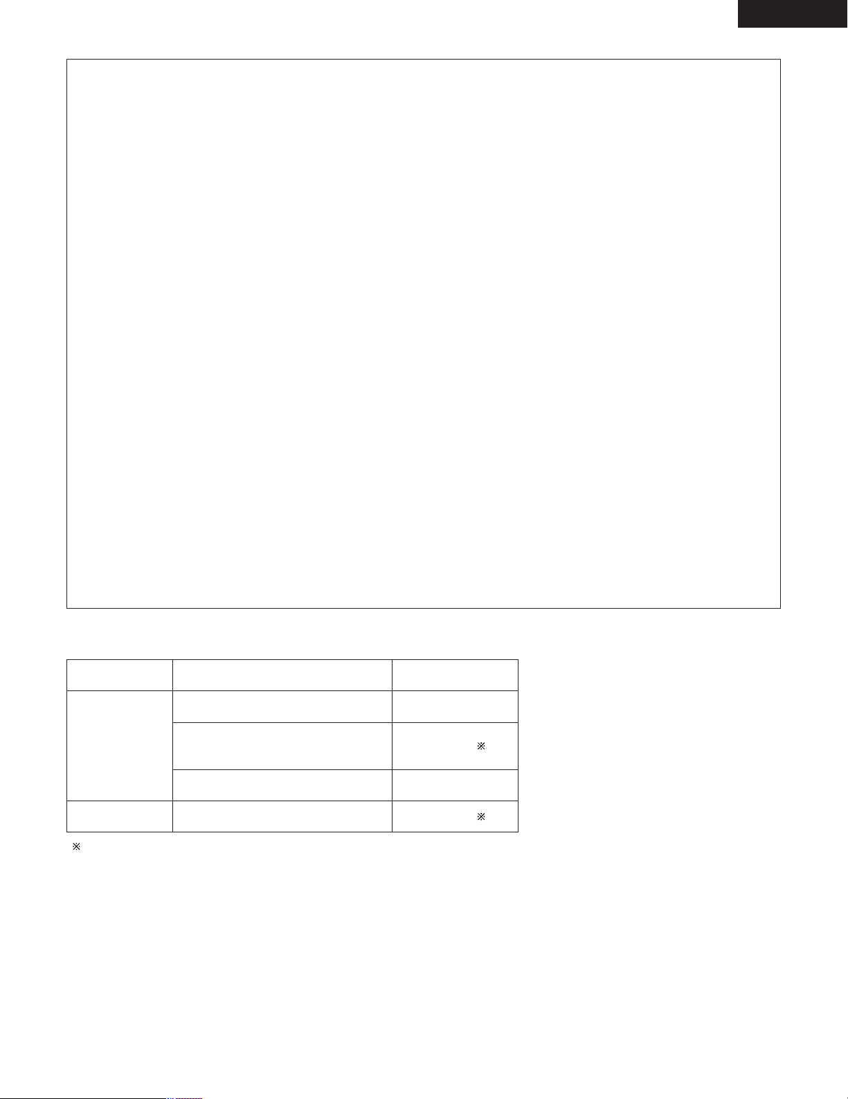
Surround parameters (5) (2-channel mode)
AUTO-ST (auto stereo) mode
2-channel sources are played in 2-channel stereo.
When this mode is selected in the auto decode mode, multi-channel sources (DVD, BS digital, etc.) are played in the multi-channel mode,
while 2-channel sources (CDs, etc.) are automatically played in stereo.
PLII CINEMA / PLII MUSIC / PRO LOGIC mode
Even 2-channel sources undergo Dolby Pro Logic II processing and are played in the multi-channel mode.
Dolby Digital Pro-Logic II processing is applied to 2-channel sources as well to play them in the multi-channel mode.
When this mode is selected in the auto decode mode, multi-channel sources (DVD, BS digital, etc.) are played in the multi-channel mode,
and 2-channel sources (CDs, etc.) are also automatically processed with Dolby Digital Pro-Logic II and played in the multi-channel mode.
• PLII CINEMA (Dolby Pro Logic II CINEMA) mode
This mode is suited for playing movies recorded in Dolby Surround as well as regular sources recorded in stereo. A high precision decoder
decodes the signals into 5 channels, resulting in uniform 360 degree surround sound even with 2-channel sources.
The MUSIC mode may be more effective for sources containing a high ratio of stereo music. Try both and choose the most effective
mode.
• PLII MUSIC (Dolby Pro Logic II MUSIC) mode
This mode is suited for surround playback of stereo music signals. The inverted phase signals (the reverberation component of the music
signals contains a high ratio of these) are played from the surround channel, and at the same time the frequency response of the surround
channel is optimized to achieve a natural sound with a sense of expansion.
With music signals, the sound field expansion differs greatly according to the type of music, the recording conditions (live, etc.) and the
contents of the signal source. Because of this, the MUSIC mode includes optional parameters for further adjusting the sound field.
• PANORAMA
The front stereo sound field image is extended to the surround channel.
This is effective if under normal conditions the stereo image is narrow and the surround effect seems weak.
• DIMENSION
This shifts the center of the sound field image to the front or surround side.
The playback balance of the different channels can be adjusted regardless of the amount of reverberation component in the source. If
the sound field image is biased towards the front or surround side, this optional parameter can be used to correct it.
• CENTER WIDTH
This adjusts the method of playback of the center signal component from the center channel only to the front channel only.
When the center channel is played in a way prioritizing separation, the position of the front channel sound field is clearer but the overall
sound field image concentrates at the center and the relationship between the different channels seems weaker. This parameter can
be adjusted to improve the sense of stability of the sound field image and achieve natural horizontal expansion.
• PRO LOGIC (Dolby Pro Logic) mode
This is the conventional Dolby Pro Logic compatible mode. In this mode sources recorded in Dolby Surround are decoded with a
playback image faithful to the original recording.
ENGLISH
• In the auto decode mode, the play mode switches automatically as shown below according to the content of the disc being played or program
being received. (When the input mode is set to “AUTO” and the 2-channel mode is set to “AUTO ST”)
Source
DVD
CD
Content
5.1/6.1-channel Dolby Digital
2-channel Dolby Digital
(including 2-channel Dolby Surround)
5.1/6.1-channel DTS digital
PCM stereo
Play mode
5.1-channel playback
Stereo playback ( )
5.1-channel playback
Stereo playback ( )
( ) To play 2-channel surround (Dolby Surround) or stereo sources in the 5.1-channel
surround mode, set the 2-channel mode to something other than “AUTO ST”.
59
Page 60
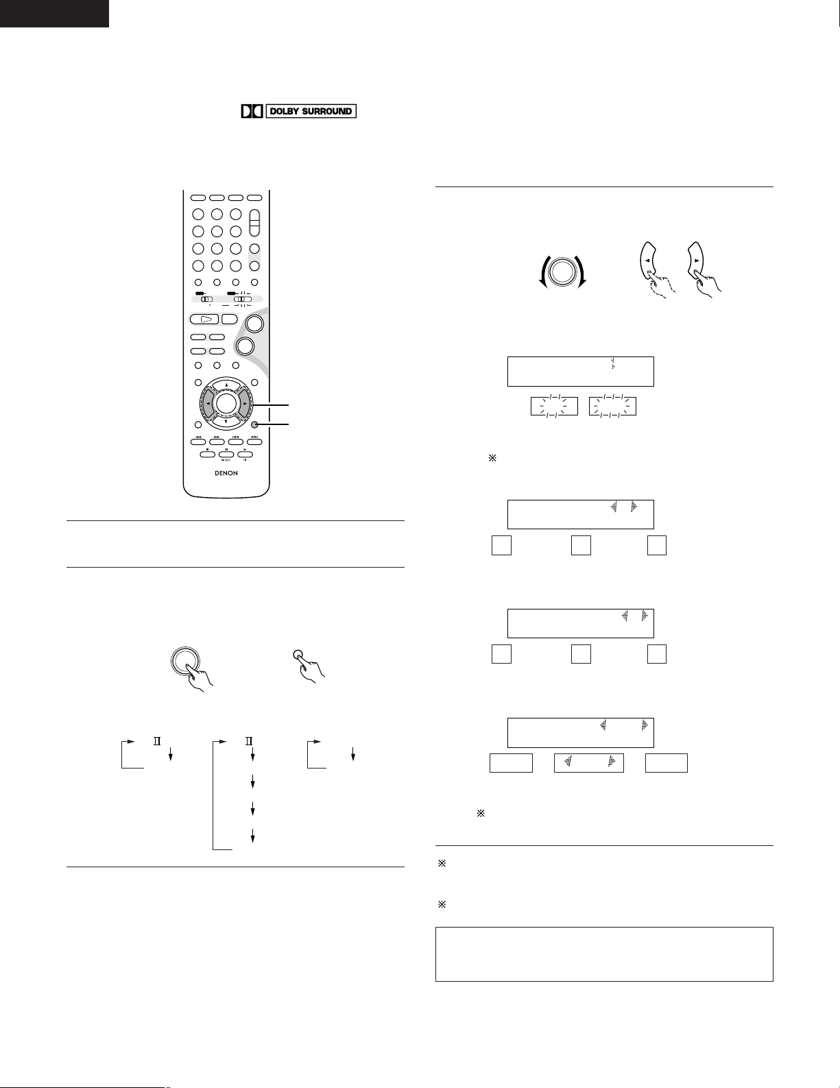
ENGLISH
+
-
+
-
RC-936
A / V
3
SEARCH MODEREPEAT RANDOMPROG/DIRECT
MEMO BANDMODE
STATUS
RETURN
ANGLE AUDIO
SUB TITLE
SETUP TONE/SDB
FUNCTIONSURROUNDINPUT MODETEST TONE
DVD
TUNER
CH
321
654
987
0
/
10
CALL
ENTER
MUTING
+
10
DISPLAY MENU
TOP MENU
SYSTEM MD
CDR TAPE
TUNER TV / VCR
SURROUND
PARAMETER
CH SELECT
CD SRS
TUNING /
TV VOL
TUNERDVD
MD/LINE-1
TAPE/LINE-2
AUTO DECODE
VIRTUALDIRECT
5CH STEREO
STEREO
D.AUX
-
+
VCR CH
IN/SURR.
IN/SURR.
DVD
9
8
21
76
+
-
3
2
SURROUND/ SELECT
PUSH - PARAM.
SURROUND
PARAMETER
DEFAULT
PL CINEMA
PANORAMA
DIMENSION
CNTR WIDTH
DEFAULT
PL MUSIC
DEFAULT
PRO LOGIC
PANORA ON OFF
ON
OFF
DIMENSION 3
CNTR WIDTH 3
DEFAULT Y/N
[3] Setting the parameters in the PLII Cinema, PLII Music and Pro Logic modes
• When PLII Cinema, PLII Music or Pro Logic is selected for the 2-channel mode, detailed parameters can be set for each of these modes.
PLII Music mode: Make the settings using the procedure below.
• Program sources including the mark and CDs and other 2-channel sources are decoded with Dolby Pro Logic II
processing and played in the multi-channel mode.
q PLII Cinema mode: This mode is suited for movies and other Dolby Surround programs.
w PLII Music mode: This mode is suited for stereo music programs.
e Pro Logic compatible mode: This is the original Dolby Surround Pro Logic mode.
Set the various surround parameters.
3
SURROUND/ SELECT
PUSH - PARAM.
Main unit Remote control unit
• Panorama setting
Select “PLII C”, “PLII M” or “PRO LOGIC” for the 2-channel
1
mode setting.
Set the surround parameters for the selected mode.
2
• The parameters switch as shown below each time one of
the buttons is pressed.
60
Main unit
Remote control unit
,/
The selected setting flashes.
• Dimension setting
... ...
0 3 6
,/
• Center Width setting
... ...
0 3 7
,/
• Default setting
YES
Y/N
NO
,/
When “YES” is selected, the settings are restored to the
factory defaults.
Once the surround parameters have been set, stop operating the
buttons. After several seconds, the normal display reappears and
the settings are automatically entered.
This completes the setting of the parameters.
NOTES:
• The 2-channel mode is set and stored in the memory individually
for the different functions.
Page 61
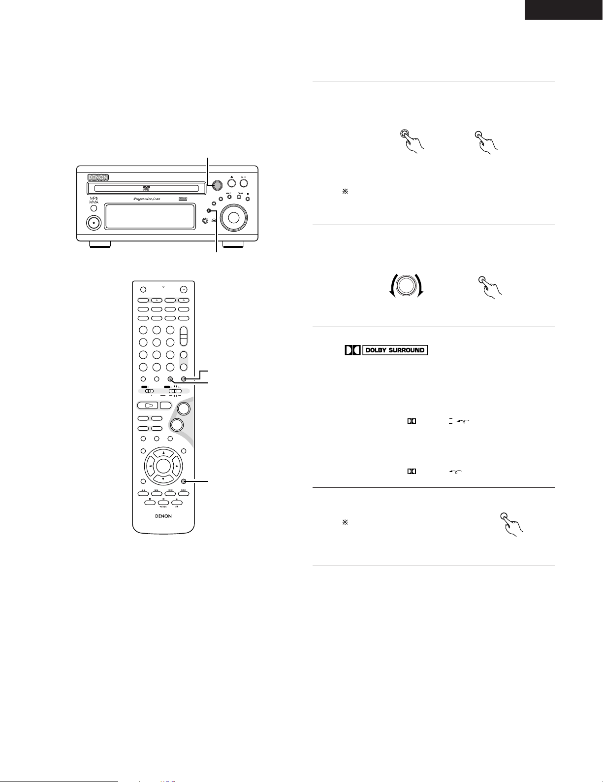
ENGLISH
B
BAND
PHONES
VOLUME
ON / STANDBY
DVD SURROUND RECEIVER ADV-M71
TONE/SDB
FUNCTION
MENU/SET
+
-
SURROUND/ SELECT
PUSH - PARAM.
VIRTUAL SPEAKER
2
1
+
-
+
-
RC-936
A / V
3
A-B REPEAT
SEARCH MODE
ONOFF
REPEAT RANDOM
CLEAR ZOOMSLIDE MODE
PROG/DIRECT
MEMO BANDMODE
STATUS
RETURN
ANGLE AUDIO
SUB TITLE
SETUP TONE/SDB
FUNCTIONSURROUNDINPUT MODETEST TONE
DVD
TUNER
CH
3
-
+
21
654
987
0
/
10
CALL
ENTER
MUTING
+
10
DISPLAY MENU
TOP MENU
SYSTEM MD
CDR TAPE
TUNER TV / VCR
SURROUND
PARAMETER
CH SELECT
VCR
NTSC/PAL
SLEEP
ENTER
CD SRS
EDIT/MENUCHARAC.
REC
TIMETITLE
TUNING /
TV VOL
TV CH TV CH
TUNERDVD
MD/LINE-1
TAPE/LINE-2
AUTO DECODE
VIRTUALDIRECT
5CH STEREO
STEREO
D.AUX
-
+
VCR CH
IN/SURR.
IN/SURR.
DVD
T VT V INSOURCE
9
8
21
76
+
-
4
1
2
FUNCTION
FUNCTION
SURROUND/ SELECT
PUSH - PARAM.
SURROUND
PRO LOGIC II
PRO LOGIC
SURROUND
PARAMETER
[4] Playing in the Dolby Pro Logic II mode (all functions)
• The source is played according to the settings that have been made for the 2-channel mode and the parameters in the PLII Cinema, PLII Music
and Pro Logic modes.
• Applicable sources
• Digital input signals (LINE-1 and D.AUX functions, including DVD
playback discs)
Dolby Digital 2-channel sources
PCM 2-channel sources
• 2-channel analog input signals (TUNER, LINE-1 and LINE-2)
Select the input function.
1
Main unit
Remote control unit
In the “DTS” input mode with the function set to a digital
input (DVD, LINE-1 or D.AUX), it is not possible to play in
the Dolby Pro Logic II mode.
Set the surround mode to “AUTO DECODE”.
2
Main unit Remote control unit
Play a program source including the
3
mark or a 2-channel source.
• The source is played according to the Dolby Pro Logic II
mode settings.
• In the Cinema and Music modes, the Dolby Pro Logic II
indicator lights.
Lit
• In the Dolby Pro Logic mode, the Dolby Pro Logic indicator
lights
Lit
Set the surround parameters
4
according to the selected mode.
Refer to steps 1 to 3 under
“Setting the parameters in the
PLII Cinema, PLII Music and Pro
Logic modes” (page 60).
Remote control unit
61
Page 62
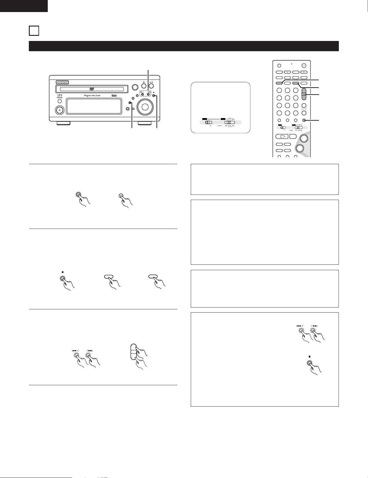
ENGLISH
B
BAND
PHONES
VOLUME
ON / STANDBY
DVD SURROUND RECEIVER ADV-M71
TONE/SDB
FUNCTION
MENU/SET
+
-
SURROUND/ SELECT
PUSH - PARAM.
VIRTUAL SPEAKER
12
3
FUNCTION
FUNCTION
BAND
RANDOM
BAND
+
-
+
-
A / V
A-B REPEAT
SEARCH MODE
ONOFF
REPEAT RANDOM
CLEAR ZOOMSLIDE MODE
PROG/DIRECT
MEMO BANDMODE
STATUS
FUNCTIONSURROUNDINPUT MODETEST TONE
DVD
TUNER
CH
3
-
+
21
654
987
0
/
10
CALL
+
10
SYSTEM MD
CDR TAPE
TUNER TV / VCR
VCR
NTSC/PAL
SLEEP
ENTER
CD SRS
EDIT/MENUCHARAC.
REC
TIMETITLE
TUNING /
TV VOL
TV CH TV CH
TUNERDVD
MD/LINE-1
TAPE/LINE-2
AUTO DECODE
VIRTUALDIRECT
5CH STEREO
STEREO
D.AUX
IN/SURR.
IN/SURR.
DVD
T VT V INSOURCE
9
8
21
76
+
-
2
2
3
1
+
-
+
-
TUNING /
A / V
SYSTEM MD
CDR TAPE
TUNER TV / VCR
IN/SURR.
IN/SURR.
DVD
PROG/DIRECT
MODE
+
-
BAND
15
LISTENING TO THE RADIO
(1) Tuning
Example: Tuning in FM/AM stations
Set the remote
control selector
switches to A/V
and TUNER.
1
2
3
62
Press the FUNCTION button and select “TUNER”.
Main unit Remote control unit
Select “FM” or “AM”.
• The selected “FM AUTO”, “FM MONO” or “AM” is
displayed.
• When using the remote control, the mode button is used to
select FM AUTO and MONO.
Main unit Remote control unit
Adjust the receiving frequency.
• When a station is received, the “TUNED” indication will
light.
Main unit Remote control unit
NOTES:
A humming sound may be heard when using a TV nearby while
receiving AM programs. If this happens, move the system as far
from the TV as possible.
Auto tuning
• When one of the Tuning +/– button is pressed, the frequency
changes in steps of 0.2 MHz in the FM band, 10 kHz in the AM
band.
• If one of the Tuning +/– button is held for over 1 second, the
frequency continues to change when the button is released
(auto tuning) and stops when a station is tuned in.Tuning will not
stop at stations whose reception is poor.
• To stop the auto tuning function, press the Tuning +/– button
once.
FM Stereo Reception
• When a program being broadcast in “FM AUTO” is received,
the “ST” indicator lights and the program is received in stereo.
• If reception is poor and there is much noise in the stereo signals,
press the BAND or MODE button to set the FM MONO mode.
About the tuning mode and the preset mode
• The function of the “–” and “+” buttons
on the main unit can be switched so that
they can be used for either tuning
(selecting the reception frequency) or for
selecting preset stations.
Main unit
• The buttons are set to the tuning mode
upon shipment. The mode can be switched
to the preset mode by pressing the “+”
button while pressing in the BAND button.
(When this is done, “PRESET” is flashes for
approximately 5 seconds.)
Main unit
• Press the “–” button while pressing in the BAND button to
switch to the tuning mode. (When this is done, “TUNING” is
flashes for approximately 5 seconds.)
Page 63
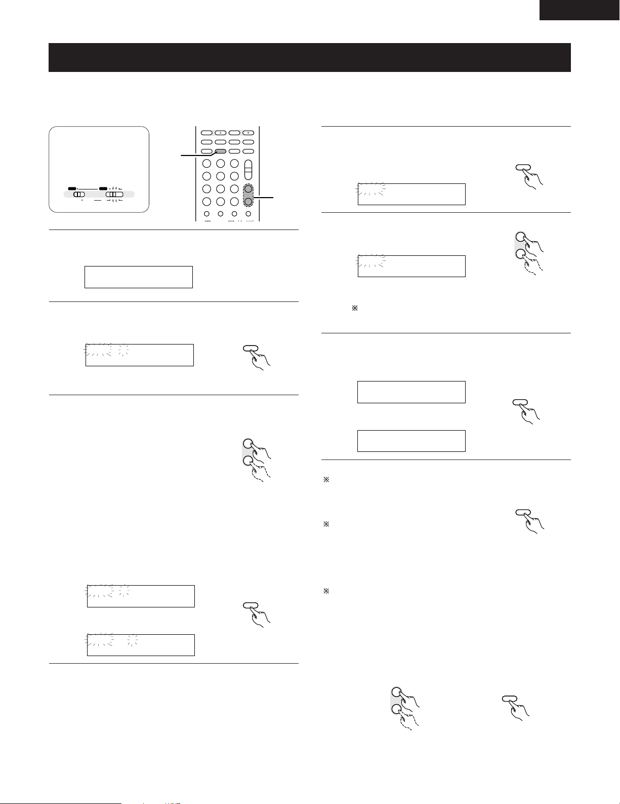
(2) Presetting stations that have been tuned in and giving names to stations (remote control unit
P0- FM 92.50M
+
-
+
-
A-B REPEAT
SEARCH MODEREPEAT RANDOM
CLEAR ZOOMSLIDE MODE
PROG/DIRECT
MEMO BANDMODE
FUNCTIONSURROUNDINPUT MODETEST TONE
TUNER
CH
3
-
+
21
654
987
0
/
10
CALL
+
10
TUNER TV / VCR
NTSC/PAL
SLEEP
ENTER
CD SRS
EDIT/MENUCHARAC.
REC
TIMETITLE
TUNING /
TV VOL
TV CH TV CH
TUNERDVD
MD/LINE-1
TAPE/LINE-2
AUTO DECODE
VIRTUALDIRECT
5CH STEREO
STEREO
D.AUX
T VT V INSOURCE
2,3,
4,6
3,5
REPEAT
MEMO
P0- _
+
-
TUNER
CH
P0- F
P0- F_
REPEAT
MEMO
REPEAT
MEMO
P0- FM-DENON
+
-
TUNER
CH
P03 FM-DENON
P03 FM 92.50M
P03 FM-DENON
REPEAT
MEMO
+
-
TUNER
CH
REPEAT
MEMO
PROG/DIRECT
MODE
A / V
SYSTEM MD
CDR TAPE
TUNER TV / VCR
IN/SURR.
IN/SURR.
DVD
only)
2 A total of 40 stations (including both FM and AM stations) can be preset.
2 Preset stations can be given names with up to 8 characters (letters, numbers and symbols).
2 Preset stations using the including remote control unit.
ENGLISH
Set the remote
control selector
switches to A/V
and TUNER.
Tune in the station you want to preset.
1
Press the MEMO button twice in a row.
2
• The name input mode is set.
Remote control unit
Use the “+” and “–” preset buttons to select the character,
3
then press the MEMO button to input that character.
Press the MEMO button twice in a row to enter the station
4
name you have input.
• The preset number indicator, “P”,
flashes.
Remote control unit
Use the “+” and “–” preset buttons to
5
select the preset number.
Remote control unit
The preset number can also be input directly using the +10
and 1 to 10 buttons on the numeric keypad.
Press the MEMO button to enter the preset number.
6
• The preset number, band and reception frequency are
displayed, then the station name appears.
\
Remote control unit
• When the “+” TUNING button or the MEMO button is
pressed, the selected character is entered, the cursor
moves to the next position and the next character can be
input.
• Use the “–” TUNING button to move back to the previous
position. Use this to correct characters that have already
been input.
To stop in the middle of the procedure,
Remote control unit
press the MODE button before pressing
the MEMO button at step 4. Everything
you have input is cleared.
To clear a station name that has been set in
the memory, call out that station, set the
name input mode in step 2, then press the
Remote control unit
MODE button. The station name is cleared
and the preset channel frequency is
displayed.
If you only want to preset a station, press the MEMO button once
\
while the station is tuned in. The preset number indicator, “P”,
flashes, and the preset number input mode is set. Use the “+” and
“–” preset buttons to select the preset number then press the
Remote control unit
MEMO button again to store that station at the selected number.
(The number can also be specified directly using the +10 and 1 to
10 buttons on the numeric keypad.)
Remote control unit Remote control unit
63
Page 64
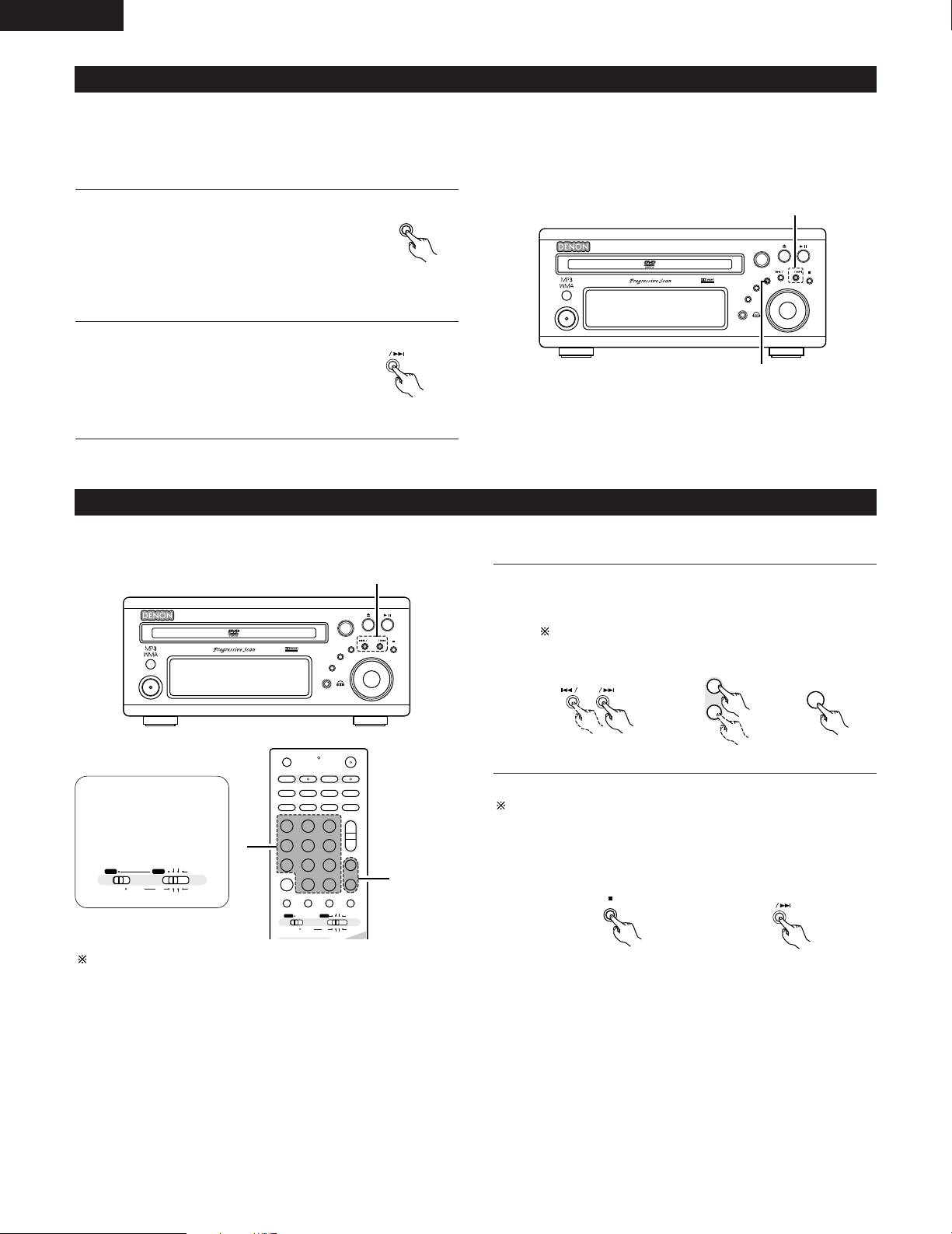
ENGLISH
B
BAND
PHONES
VOLUME
ON / STANDBY
DVD SURROUND RECEIVER ADV-M71
TONE/SDB
FUNCTION
MENU/SET
+
-
SURROUND/ SELECT
PUSH - PARAM.
VIRTUAL SPEAKER
1
2
MENU/ SET
+
B
BAND
PHONES
VOLUME
ON / STANDBY
DVD SURROUND RECEIVER ADV-M71
TONE/SDB
FUNCTION
MENU/SET
+
-
SURROUND/ SELECT
PUSH - PARAM.
VIRTUAL SPEAKER
1
+
-
TUNER
CH
3
D.AUX
+
-
BAND
+
+
-
+
-
A / V
A-B REPEAT
SEARCH MODE
ONOFF
REPEAT RANDOM
CLEAR ZOOMSLIDE MODE
PROG/DIRECT
MEMO BANDMODE
FUNCTIONSURROUNDINPUT MODETEST TONE
TUNER
CH
3
-
+
21
654
987
0
/
10
CALL
+
10
SYSTEM MD
CDR TAPE
TUNER TV / VCR
VCR
NTSC/PAL
SLEEP
ENTER
CD SRS
EDIT/MENUCHARAC.
REC
TIMETITLE
TUNING /
TV VOL
TV CH TV CH
TUNERDVD
MD/LINE-1
TAPE/LINE-2
AUTO DECODE
VIRTUALDIRECT
5CH STEREO
STEREO
D.AUX
IN/SURR.
IN/SURR.
DVD
T VT V INSOURCE
1
1
A / V
SYSTEM MD
CDR TAPE
TUNER TV / VCR
IN/SURR.
IN/SURR.
DVD
(3) Auto tuner presets
Use this to automatically search for FM broadcasts and store up to 40 stations at preset channels 1 to 40.
NOTE:
• If an FM station cannot be preset automatically due to poor reception, use the “Manual tuning” operation to tune in the station, then preset it
using the manual “Preset memory” operation.
Using the TUNER function, press and
1
hold the MENU/SET button of the main
unit for 2 seconds or longer.
• “AUTO PRESET?” and “–: NO/+:
START” will alternately appear on the
display of the main unit.
• Press the TUNING – button to cancel.
Use the TUNING + button to select
2
“START”.
“SEARCH” flashes on the display and
searching begins.
“COMPLETED” appears once searching is
completed.
Main unit
Main unit
(4) Listening to preset stations
Example: Listening to the station preset at number P03 (This operation is only possible from the remote control unit.)
Use the “+” and “–” preset buttons to select preset number
1
“3” or press the “3” button on the numeric keypad to display
preset number “P03”.
The “+” and “–” buttons on the main unit can be selected
when the preset mode has been set.
Main unit
Remote control unit
Set the remote
control selector
switches to A/V
and TUNER.
The functions of the “+” and “–” buttons on the main unit change
according to whether the tuning or preset mode is set. When the
tuning mode is set, you can switch to the preset mode by pressing
the “+” button while pressing the BAND button.
The preset buttons on the remote control unit (TUNER CH “+” and
“–”) can be used at any time.
64
Main unit Main unit
Page 65
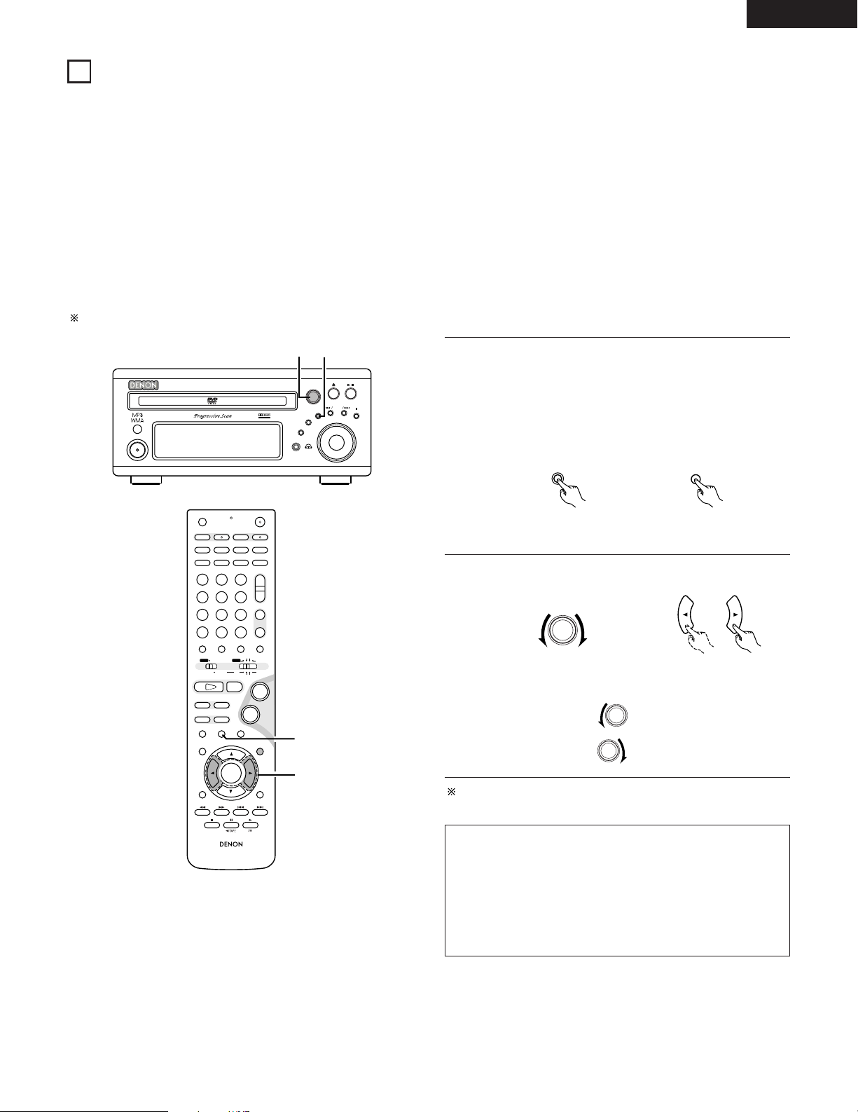
ENGLISH
B
BAND
PHONES
VOLUME
ON / STANDBY
DVD SURROUND RECEIVER ADV-M71
TONE/SDB
FUNCTION
MENU/SET
+
-
SURROUND/ SELECT
PUSH - PARAM.
VIRTUAL SPEAKER
12
+
-
+
-
RC-936
A / V
3
A-B REPEAT
SEARCH MODE
ONOFF
REPEAT RANDOM
CLEAR ZOOMSLIDE MODE
PROG/DIRECT
MEMO BANDMODE
STATUS
RETURN
ANGLE AUDIO
SUB TITLE
SETUP TONE/SDB
FUNCTIONSURROUNDINPUT MODETEST TONE
DVD
TUNER
CH
3
-
+
21
654
987
0
/
10
CALL
ENTER
MUTING
+
10
DISPLAY MENU
TOP MENU
SYSTEM MD
CDR TAPE
TUNER TV / VCR
SURROUND
PARAMETER
CH SELECT
VCR
NTSC/PAL
SLEEP
ENTER
CD SRS
EDIT/MENUCHARAC.
REC
TIMETITLE
TUNING /
TV VOL
TV CH TV CH
TUNERDVD
MD/LINE-1
TAPE/LINE-2
AUTO DECODE
VIRTUALDIRECT
5CH STEREO
STEREO
D.AUX
-
+
VCR CH
IN/SURR.
IN/SURR.
DVD
T VT V INSOURCE
9
8
21
76
+
-
1
2
MENU/ SET
STATU S
SURROUND/ SELECT
PUSH - PARAM.
16
ON-SCREEN DISPLAY
• The ADV-M71 is equipped with an on-screen display (“OSD”) function that displays various types of information on the surround functions and
the disc on the screen when the function is set to DVD.
q Setup screen
• This is used to select the speaker system being used (quick system setting) and to change the function of the ADV-M71 and various settings
when playing discs (system setting change and DVD setting change).
• The setup screen can be used regardless of the currently set function.
w Display of disc information
• When the function is set to DVD, the OSD displays information on the disc and appears when various playback functions are operated.
e Display of surround function
• When the function is set to DVD, information on the surround amplifier is also displayed and can be operated.
• The OSD for the surround function (AV OSD) can be turned on and off.
(The OSD for the setup screen and DVD disc information cannot be set to
Set to “ON” upon shipment from the factory.
“
OFF”.)
With the function set to DVD, press the STATUS button of the
1
remote control for at least 2 seconds.
Press in the MENU/SET button on the main unit, then press
the MENU/SET button again for at least 2 seconds while
“STATUS” is displayed.
• “AV OSD ON 0:1 OFF” is displayed.
Main unit Remote control unit
Turn the AV OSD on or off.
2
Main unit Remote control unit
or 0 :ON
After several seconds, the display turns off and the setting is
made.
NOTES:
• Depending on the disc being played, the picture may be
disturbed when the OSD turns on. This is not a malfunction.
If this should happen, set the AV OSD to “OFF”.
• The OSD is also output to the VCR video output terminals.
Do not perform setup or OSD operations while recording with a
video deck.
or 1 :OFF
65
Page 66
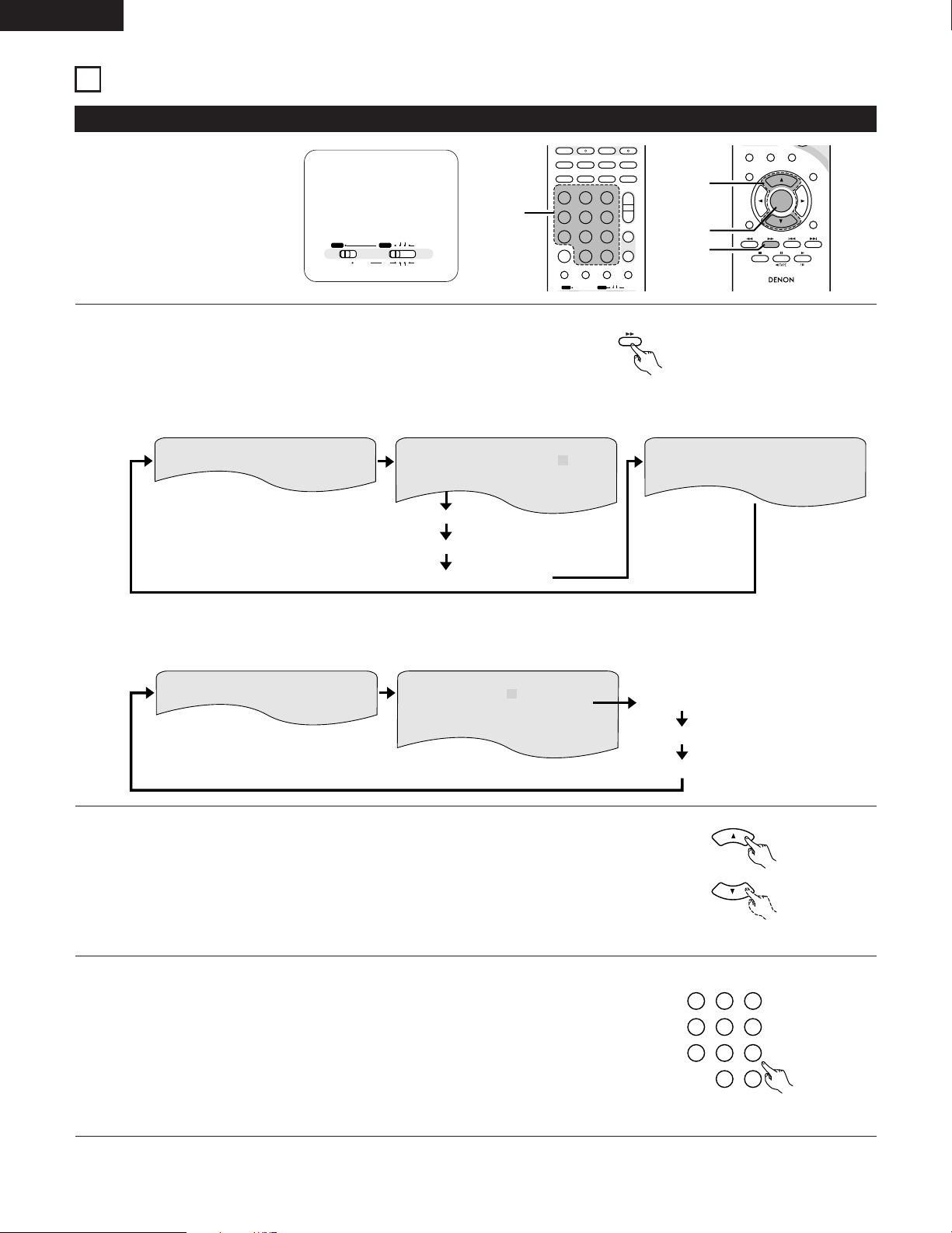
ENGLISH
DISPLAY
321
654
987
0
/
10
+
10
TUNERDVD
MD/LINE-1
TAPE/LINE-2
AUTO DECODE
VIRTUAL
5CH STEREO
STEREO
D.AUX
+
-
+
-
A / V
A-B REPEAT
SEARCH MODEREPEAT RANDOM
CLEAR ZOOMSLIDE MODE
PROG/DIRECT
MEMO BANDMODE
FUNCTIONSURROUNDINPUT MODETEST TONE
TUNER
CH
3
-
+
21
654
987
0
/
10
CALL
+
10
TUNER TV / VCR
NTSC/PAL
SLEEP
ENTER
CD SRS
EDIT/MENUCHARAC.
TIMETITLE
TUNING /
TV VOL
TV CH TV CH
TUNERDVD
MD/LINE-1
TAPE/LINE-2
AUTO DECODE
VIRTUALDIRECT
5CH STEREO
STEREO
D.AUX
IN/SURR.
DVD
T VT V INSOURCE
3
RC-936
3
STATUS
RETURN
ANGLE AUDIO
SUB TITLE
SETUP TONE/SDB
ENTER
MUTING
DISPLAY MENU
TOP MENU
SURROUND
PARAMETER
CH SELECT
-
+
VCR CH
1
2
3
A / V
SYSTEM MD
CDR TAPE
TUNER TV / VCR
IN/SURR.
IN/SURR.
DVD
TRACK 01 / 10
26 : 11S INGL E T IME
TOTAL TIME
PI C TURE MODE
STANDARD
S INGL E REMAIN 03 : 17
TOTAL TIME 06 : 15
TOTAL REMAIN 32 : 05
CHAPTE R 01/10
00 : 00 : 01
STANDARD
AUDI O
: OFF
SUBT ITLE 1/2 : DOLBY D 3/2/1 ENGLISH
01 : 10 : 59
00 : 00 : 01
00 : 40 : 59
T ITLE 01 /1 0
TITLE T IME
CHAPTE R T IME
CHAPTE R REMAIN
TITLE REMAIN
PI C TURE MODE
17
(1) Operating using the disc information OSD
USING THE ON-SCREEN DISPLAY
2 Use this function to display and
change information on the disc
(titles, chapters, time, etc.)
Set the remote
control selector
switches to A/V
and DVD.
In the play mode, press the DISPLAY button.
1
• The On-Screen Display appears.
• The picture on the TV screen switches each time the button is
pressed.
• The items displayed differ from disc to disc.
Example: For DVDs
Remote control unit
66
Example: For video and music CDs
Use the and •, ª cursor buttons to select the item you wish to change.
2
• The selected item is displayed with a yellow frame.
q For DVDs
“TITLE”, “CHAPTER”, “TITLE ELAPSED” can be selected.
w For video and music CDs
“TRACK” can be selected.
q Changing the elapsed time
3
Input using the number buttons, then press the ENTER button.
Example: For 1 minute 26 seconds / “00126”
w Changing the title, track or chapter
• For DVDs
Input using the number buttons, then press the ENTER button.
(For some discs it is not possible to change the title or chapter.)
• For video and music CDs
Input using the number buttons. Playback starts from that track.
• For the on-screen display for video CDs and music
CDs, only the disc time changes.
Remote control unit
Remote control unit
Page 67
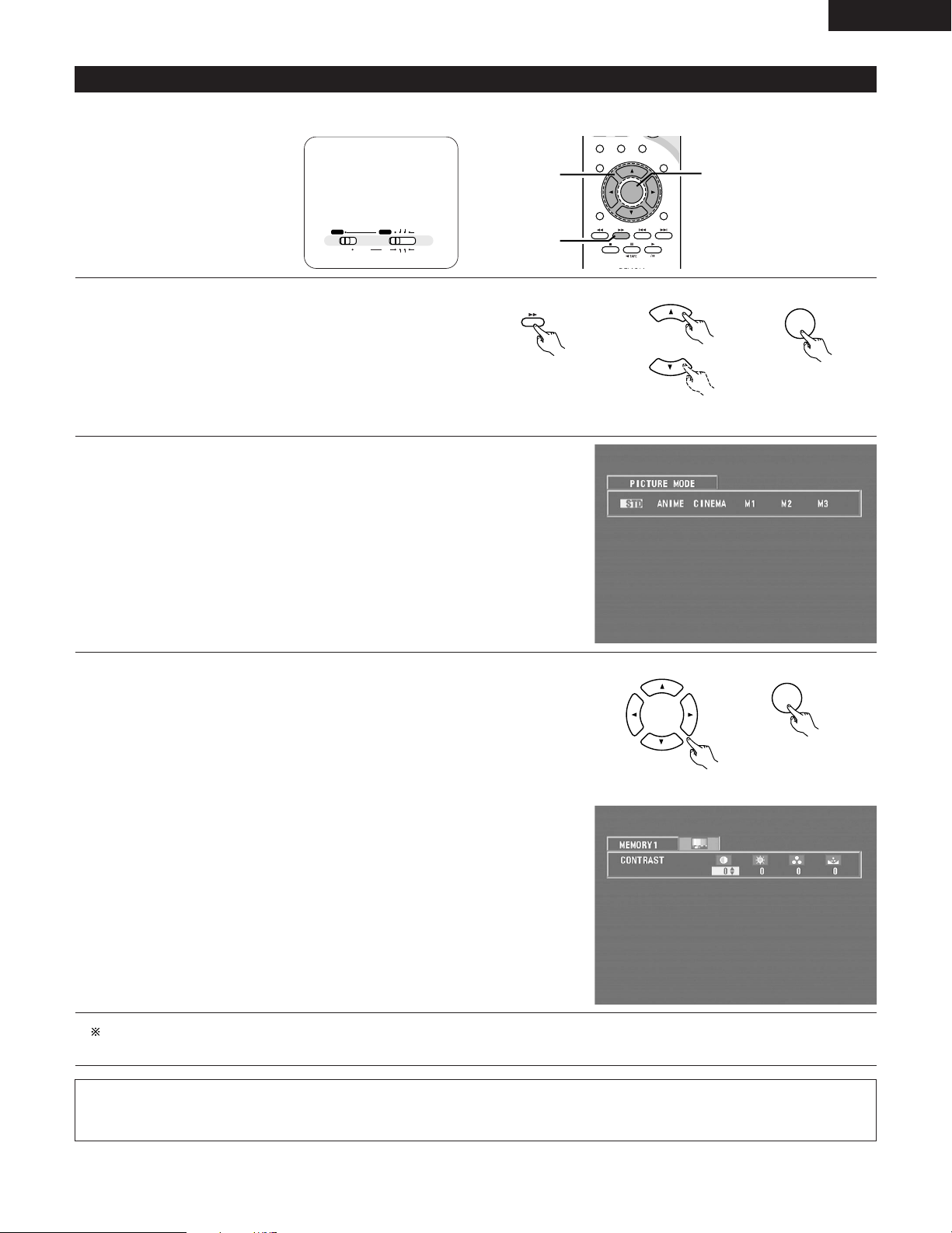
(2) Adjusting the picture quality
3
STATUS
RETURN
ANGLE AUDIO
SUB TITLE
SETUP TONE/SDB
ENTER
MUTING
DISPLAY MENU
TOP MENU
SURROUND
PARAMETER
CH SELECT
-
+
VCR CH
1
1,2,3
1,2
ENTER
DISPLAY
ENTER
A / V
SYSTEM MD
CDR TAPE
TUNER TV / VCR
IN/SURR.
IN/SURR.
DVD
• The quality of the picture when playing discs can be adjusted.
Set the remote
control selector
switches to A/V
and DVD.
When playing a disc with the function set to DVD, press the
1
DISPLAY button to turn on the on-screen display, use the • and ª
cursor buttons to select “PICTURE MODE”, then press the
ENTER button.
• The picture quality adjustment screen appears.
• The on-screen display also turns on when the DISPLAY button
is pressed in the stop mode.
Use the 0 and 1 cursor buttons to select the item, then press the ENTER button.
2
Standard:
Both the picture quality and functions are set back to the standard settings set
upon shipment from the factory.
Anime:
This sets a brighter more vivid picture quality.
Cinema:
This sets a mellower picture quality.
Memory 1 to 3:
Picture quality settings you have adjusted can be stored at three memory
positions. (Set at step 3)
Remote control unit
\
Remote control unit
ENGLISH
\
Remote control unit
Selecting and adjusting the picture quality
3
Use the 0 and 1 cursor buttons to select the picture quality item, then use the •
and ª cursor buttons to adjust the value.
• All the adjustments are stored in the memory.
\
Contrast (-6 to +6) (factory default: 0):
This adjusts the contrast between light and dark portions of the picture.
Brightness (0 to +12) (factory default: 0):
This adjust the brightness (vividness) of the picture.
Remote control unit
Remote control unit
Color density (-6 to +6) (factory default: 0):
This adjusts the color density.
Hue (-6 to +6) (factory default: 0):
This adjusts the balance between green and red. (This setting does not affect
progressive scan outputs.)
To complete the picture quality adjustment:
Press the DISPLAY button again.
NOTE:
• Depending on the disc being played, the picture or sound may be disturbed when the on-screen display is displayed. This is not a
malfunction.
67
Page 68
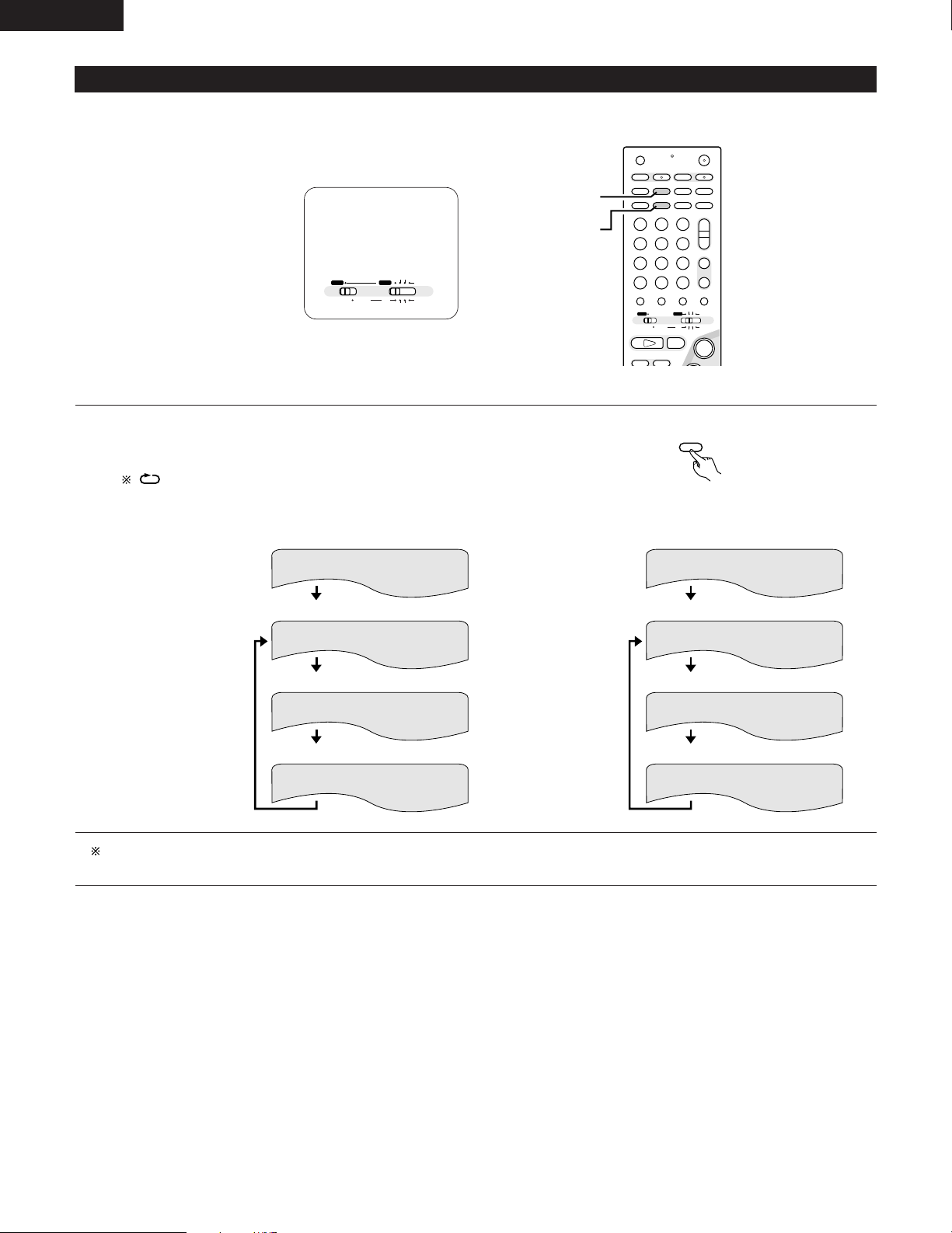
ENGLISH
+
-
+
-
A / V
A-B REPEAT
SEARCH MODE
ONOFF
REPEAT RANDOM
CLEAR ZOOMSLIDE MODE
PROG/DIRECT
MEMO BANDMODE
FUNCTIONSURROUNDINPUT MODETEST TONE
DVD
TUNER
CH
3
-
+
21
654
987
0
/
10
CALL
+
10
SYSTEM MD
CDR TAPE
TUNER TV / VCR
VCR
NTSC/PAL
SLEEP
ENTER
CD SRS
EDIT/MENUCHARAC.
REC
TIMETITLE
TUNING /
TV VOL
TV CH TV CH
TUNERDVD
MD/LINE-1
TAPE/LINE-2
AUTO DECODE
VIRTUALDIRECT
5CH STEREO
STEREO
D.AUX
IN/SURR.
IN/SURR.
DVD
T VT V INSOURCE
9
8
21
+
[2]-1,2
[1]-1
REPEAT
MEMO
A / V
SYSTEM MD
CDR TAPE
TUNER TV / VCR
IN/SURR.
IN/SURR.
DVD
(3) Playing Repeatedly
2 Use this function to play your favourite audio or video sections repeatedly.
Set the remote
control selector
switches to A/V
and DVD.
[1] Playing Repeatedly (Repeat Playback)
In the play mode, press the REPEAT button.
1
• The display on the TV screen switches each time the button is
pressed, and the corresponding repeat play or stop mode is set.
lights on the display when the repeat play mode is set. “ALL”
lights when the all repeat play mode is set.
q For DVDs
Remote control unit
w For video and music CDs
• Normal playback
• Chapter repeated
• Title repeated
CHAPTER REPEAT
TITLE REPEAT
• Normal playback
• Track repeated
• Entire disc
TRACK REPEAT
DISC REPEAT
repeated
• Repeat playback
cancelled
REPEAT OFF
• Repeat playback
cancelled
REPEAT OFF
To return to normal playback:
Return to normal playback by pressing the REPEAT button until “REPEAT OFF” appears on the TV screen.
68
Page 69
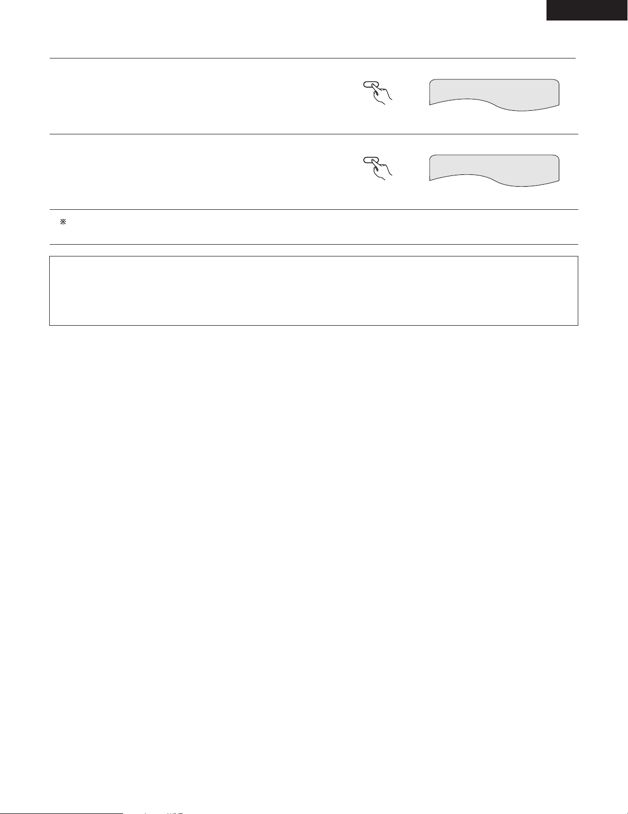
[2] Playing a Certain Section Repeatedly (A-B Repeat Playback)
A-B REPEAT
ENTER
A-B REPEAT
ENTER
During playback, press the A-B REPEAT button.
1
• This sets start point A.
Remote control unit
Press the A-B REPEAT button again.
2
• This sets end point B, and repeat playback of the A-B section
starts.
Remote control unit
To return to normal playback:
Press the A-B REPEAT button until “A TO B CANCELLED” appears on the TV screen.
NOTES:
• Repeat playback may not work for some DVDs.
• The repeat playback and A-B repeat playback functions will not work for DVDs and video CDs for which the elapsed time is not shown
on the display during playback.
• In some cases, subtitles may not be displayed near the A and B points during A-B repeat playback.
A TO B SET A
A TO B SET B
ENGLISH
69
Page 70
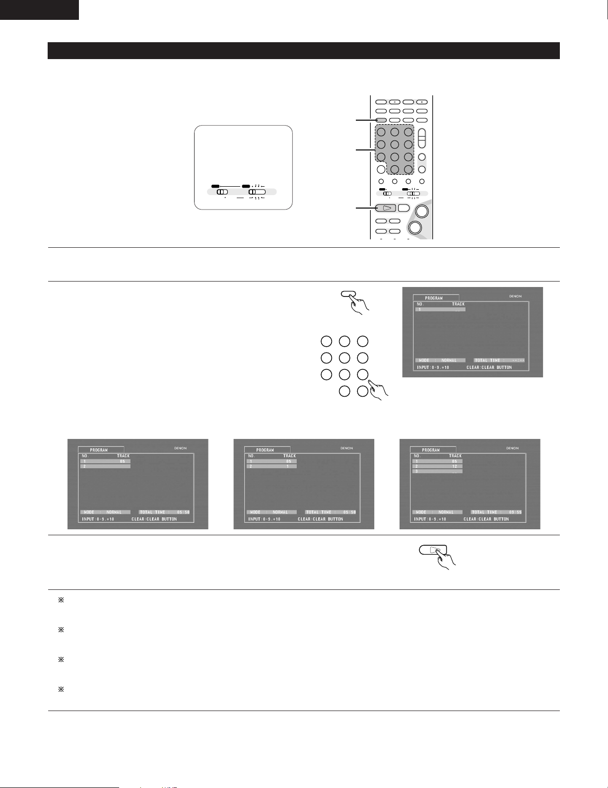
ENGLISH
321
654
987
0
/
10
+
10
TUNERDVD
MD/LINE-1
TAPE/LINE-2
AUTO DECODE
VIRTUAL
5CH STEREO
STEREO
D.AUX
DVD
1
PROG/DIRECT
MODE
+
-
+
-
A / V
A-B REPEAT
SEARCH MODEREPEAT RANDOM
CLEAR ZOOMSLIDE MODE
PROG/DIRECT
MEMO BANDMODE
STATUS
FUNCTIONSURROUNDINPUT MODETEST TONE
DVD
TUNER
CH
3
-
+
21
654
987
0
/
10
CALL
+
10
SYSTEM MD
CDR TAPE
TUNER TV / VCR
NTSC/PAL
SLEEP
ENTER
CD SRS
EDIT/MENUCHARAC.
REC
TIMETITLE
TUNING /
TV VOL
TV CH TV CH
TUNERDVD
MD/LINE-1
TAPE/LINE-2
AUTO DECODE
VIRTUALDIRECT
5CH STEREO
STEREO
D.AUX
IN/SURR.
IN/SURR.
DVD
T VT V INSOURCE
9
8
21
76
+
-
1
2
3
A / V
SYSTEM MD
CDR TAPE
TUNER TV / VCR
IN/SURR.
IN/SURR.
DVD
(4) Playing Tracks in the Desired Order
2 Use this function with video and music CDs to play the tracks in the desired order.
2 This function does not affect with DVD.
Set the remote
control selector
switches to A/V
and DVD.
Press the PROG/DIRECT button once in the stop mode.
1
• The program selection screen appears.
Use the number buttons to select the number you want to
2
program.
• Up to 20 tracks can be programmed.
Remote control unit
70
Remote control unit
Example: To program tracks 5 and 12
Press number button “5”.
Press number button “+10”. Press number button “2”.
\\
Press the play button.
3
• The tracks start playing in the programmed order.
Remote control unit
To return to normal playback:
Press the stop button to stop programmed playback, then press the PROG/DIRECT button.
When the play button is next pressed, normal playback begins from the beginning of the disc.
Clearing individual tracks from the program:
Press the stop button to stop programmed playback.
Now press the CLEAR button to clear the last track programmed.
Clearing the entire program:
The entire program is cleared when the power is turned off or the disc is unloaded.
The entire program can also be cleared by pressing the stop button to stop programmed playback then pressing the PROG/DIRECT button.
Checking the programmed tracks:
Press the CALL button to display the programmed tracks in steps.
Page 71
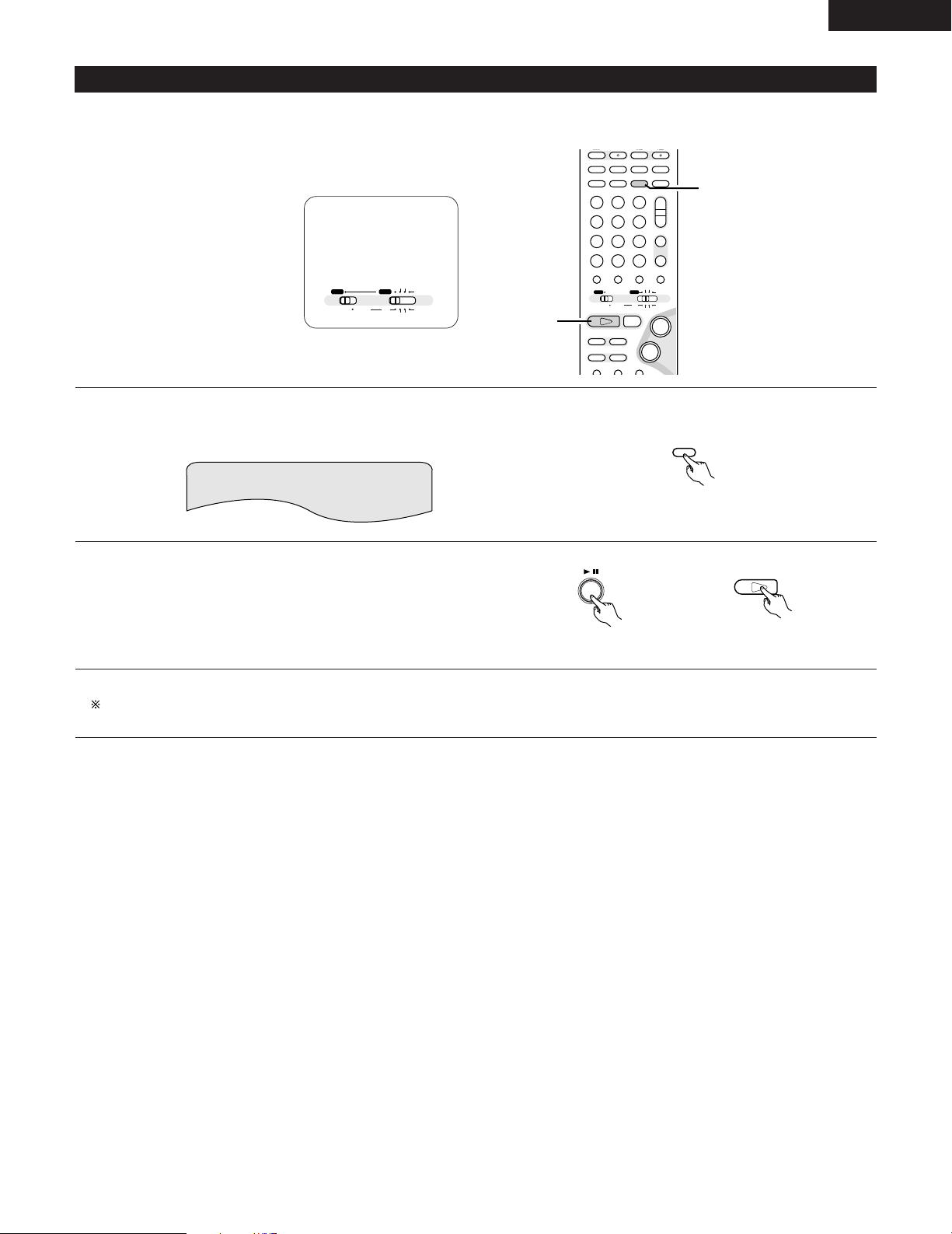
(5) Playing Tracks in the Random Order
RANDOM
BAND
DVD
1
+
-
+
-
A / V
A-B REPEAT
SEARCH MODEREPEAT RANDOM
CLEAR ZOOMSLIDE MODE
PROG/DIRECT
MEMO BANDMODE
STATUS
FUNCTIONSURROUNDINPUT MODETEST TONE
DVD
TUNER
CH
3
-
+
21
654
987
0
/
10
CALL
+
10
SYSTEM MD
CDR TAPE
TUNER TV / VCR
NTSC/PAL
SLEEP
ENTER
CD SRS
EDIT/MENUCHARAC.
TIMETITLE
TUNING /
TV VOL
TV CH TV CH
TUNERDVD
MD/LINE-1
TAPE/LINE-2
AUTO DECODE
VIRTUALDIRECT
5CH STEREO
STEREO
D.AUX
IN/SURR.
IN/SURR.
DVD
T VT V INSOURCE
9
8
21
76
+
-
1
2
A / V
SYSTEM MD
CDR TAPE
TUNER TV / VCR
IN/SURR.
IN/SURR.
DVD
2 Use this function with video and music CDs to play the tracks in random order.
2 This function does not affect with DVD.
Set the remote
control selector
switches to A/V
and DVD.
In the stop mode, press the RANDOM button.
1
• The random play screen appears.
RANDOM ON
ENGLISH
Press the PLAY (1) button.
2
• The tracks start playing in random order.
• Random playback is not possible for some discs.
To return to normal playback:
Press the STOP (
2) button to stop random playback, then press the RANDOM button once.
Remote control unit
Main unit Remote control unit
71
Page 72
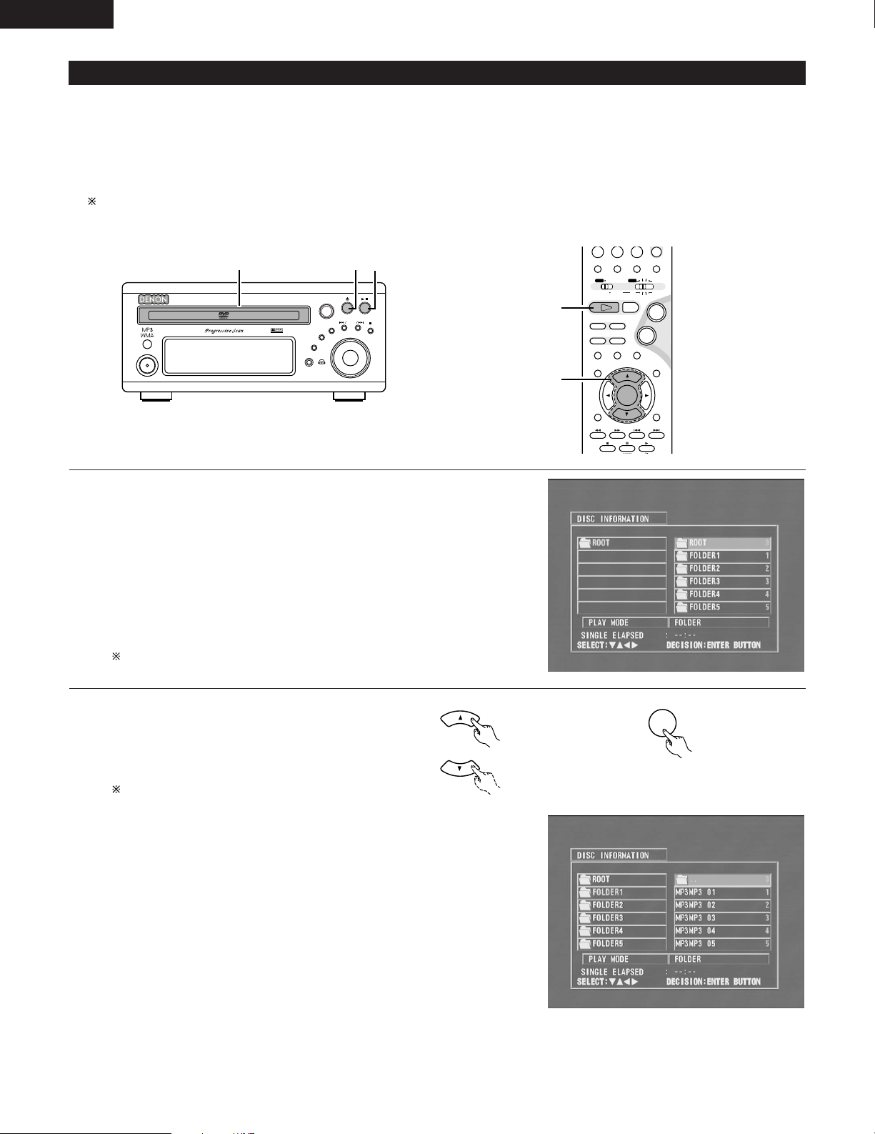
ENGLISH
ENTER
-
A / V
3
STATUS
RETURN
ANGLE AUDIO
SUB TITLE
SETUP TONE/SDB
FUNCTIONSURROUNDINPUT MODETEST TONE
DVD
0
/
10
CALL
ENTER
MUTING
+
10
DISPLAY MENU
TOP MENU
SYSTEM MD
CDR TAPE
TUNER TV / VCR
SURROUND
PARAMETER
CH SELECT
-
+
VCR CH
IN/SURR.
IN/SURR.
DVD
9
8
21
76
+
-
2,3
3
B
BAND
PHONES
VOLUME
ON / STANDBY
DVD SURROUND RECEIVER ADV-M71
TONE/SDB
FUNCTION
MENU/SET
+
-
SURROUND/ SELECT
PUSH - PARAM.
VIRTUAL SPEAKER
113
(6) MP3 WMA Playback
[1] Listening to Recorded MP3 CD/CD-R/CD-RW
2 There are many music distribution sites on the internet from which music files in MP3 format can be downloaded. Music downloaded as
instructed on the site and written onto a CD-R/RW disc can be played on the ADV-M71.
If music recorded on commercially available music CDs is converted on a computer into MP3 files using an MP3 encoder (conversion software),
the data on a 12 cm CD is reduced into about 1/10 the amount of the original data. Thus, when written in MP3 format, the data of about 10
music CDs can fit onto a single CD-R/RW disc. A single CD-R/RW disc can contain over 100 tracks.
Values when 5-minute tracks are converted with a standard bit rate of 128 kbps into MP3 files and using a CD-R/RW disc with a capacity
of 650 MB.
Load the CD-R/RW disc on which the MP3 format
1
music files have been written into this unit. (See page
39.)
• When the disc is loaded in the ADV-M71, the disc
information screen appears.
• If there are multiple folders, proceed to step 2.
• If there are no folders on the disc (if the disc only
contains MP3 files), proceed to step 3.
All the folders recorded on the disc are displayed.
(The folders are not displayed by layer.)
Use the • and ª cursor buttons to select the folder
2
containing the file(s) you want to play, then press the
ENTER button.
To change the folder
Use the •cursor button to select “ROOT” at the
upper right of the screen, then press the ENTER
button. The screen in step 1 reappears. Select the
desired folder.
\
Remote control unit
Remote control unit
72
Page 73
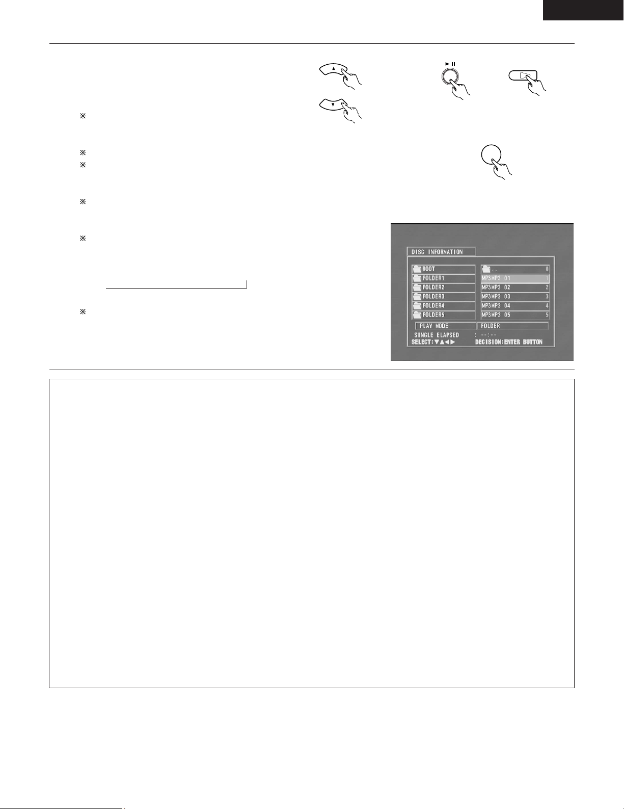
DVD
1
Use the •and ªcursor buttons to select the MP3 file you
ENTER
3
want to play, then press the PLAY (
button.
• Playback starts.
1
) button or ENTER
ENGLISH
\
The display can be switched between the single elapsed
time and the single remaining time by pressing the
DISPLAY button.
Programmed playback is not possible with MP3 discs.
To change the MP3 file
Press the STOP button, then use the •and ªcursor
buttons to reselect the desired MP3 file.
To set the random play mode
In the stop mode, press the RANDOM button.
1
Then press the PLAY (
To set the repeat mode
The repeat mode changes each time the REPEAT button is
pressed.
NORMAL ÆTRACK REPEAT ÆFOLDER REPEAT
≠
To return to the initial disc information screen
Press the STOP (
select “ROOT” at the upper right of the screen, then press
the ENTER button.
The screen in step 1 reappears.
NOTES:
• The ADV-M71 is compatible with the “MPEG-1 Audio Layer 3” standards (sampling frequency of 32, 44.1 or 48 kHz). It is not compatible
with such other standards as “MPEG-2 Audio Layer 3”, “MPEG-2.5 Audio Layer 3”, MP1, MP2, etc.
• It may not be possible to play some CD-R/RW discs due to disc properties, dirt, warping, etc.
• The digital signals output when playing MP3 files are MP3 signals converted into PCM, regardless of whether the audio output presenting
is set to “normal” or “PCM conversion”. The signals are output with the same sampling frequency as that of the music source.
• In general, the higher an MP3 file’s bit rate, the better the sound quality. On the ADV-M71, we recommend using MP3 files recorded with
bit rates of 128 kbps or greater.
• MP3 files may not be played in the expected order, since the writing software may change the position of the folders and the order of
the files when writing them on the CD-R/RW.
• Manual search and programmed playback are not possible with MP3 discs.
• When writing MP3 files on CD-R/RW discs, select “ISO9660 level 1” as the writing software format. This may not be possible with some
types of writing software. For details, refer to the writing software’s usage instructions.
• With the ADV-M71 it is possible to display folder names and file names on the screen like titles. The ADV-M71 can display up to 11
characters, consisting of numbers, capital letters, and the “_” (underscore) mark.
• If recorded in a format other than “ISO9660 level 1”, normal display and playback may not be possible. In addition, folder and file names
including other symbols will not be displayed properly.
• Be sure to add the extension “.MP3” to MP3 files. Files cannot be played if they have any extension other than “.MP3” or if they have
no extension. (with Macintosh computers, MP3 files can be played by adding the extension “.MP3” after the file name consisting of up
to 8 capital or numbers and recording the files on the CD-R/RW.)
• Do not apply stickers, tape, etc., to either the label side or the signal side of CD-R/RW discs. If adhesive gets on the surface of a disc,
the disc may get stuck inside the ADV-M71 and be impossible to eject.
• The ADV-M71 is not compatible with packet write software.
• The ADV-M71 is not compatible with ID3-Tag.
• The ADV-M71 is not compatible with play lists.
) button or ENTER button.
2
) button, use the •cursor button to
Remote control unit
\
Main unit
Remote control unit
Remote control unit
73
Page 74
ENGLISH
[2] Listening to Recorded WMA (Windows Media Audio) CD-R/CD-RW
• This unit can play CD-R/RW music files that have been recorded in the WMA (Windows Media Audio)* audio compression format.
Windows Media, and the Windows logo are trademarks, or registered trademarks of Microsoft Corporation in the United
States and/or other countries.
WMA (Windows Media Audio): New audio coding of Microsoft Corporation (U.S.A.)
• Uses of recordings you have made other than for your personal enjoyment are not permitted under the Copyright Law without permission
of the copyright holder.
• The method of playback is the same as “[1] Listening to Recorded MP3 CD/CD-R/CD-RW” on Pages 72 and 73.
• In the file display of the disc information screen, WMA files will be displayed with the “WMA” icon instead of the “MP3” icon.
(Files for which the “WMA” icon is not displayed cannot be played.)
NOTES:
• Files recorded with a sampling frequency (fs) of 32, 44.1, and 48 kHz are supported.
• Programmed playback cannot be performed with WMA files.
• The digital output at the time of WMA file playback is converted to PCM regardless of the initial settings.
• Please use discs that have been recorded in conformity with the ISO 9660 level 1/level 2 CD-ROM file system. (Extended formats are
excluded.)
• Copyright protected files cannot be played. Also note that depending on the writing software and conditions, playback might not be
possible, or the files might not be displayed properly.
• Playback of the CD-R/RW might not be possible depending on the disc characteristics, soiling, scratches, and other factors.
• Bit rates of 64 k to 160 kbps are supported for WMA files that have an extension of “.wma” or “.WMA”.
• This unit can display the folder names and file names on the screen. Up to 11 half-width alphanumeric upper case characters and symbols
(including the underscore symbol) can be displayed.
• While in the stop condition, the DISPLAY button of the remote control can be used to switch and display the title names and the artist
names. (One folder has a capacity of up to 99 files.)
• Recorded discs with no more than 99 files per folder are recommended. Multiple folder configurations are possible; however, depending
on the configuration, playback of all the folders and files might not be possible.
• Multi-session discs and CD-R/RW that have not been finalized can also be played back; however, playback of discs that have had session
closure within 10 sessions or have been finalized is recommended.
• Direct track selection using the remote control numerical keys (0 to 9, and +10) can specify up to 179 tracks (179 files) per folder. When
179 tracks are exceeded, while the unit is stopped use the cursor buttons at the disc information screen to select the files, and use the
play button of the ENTER button to play.
74
Page 75
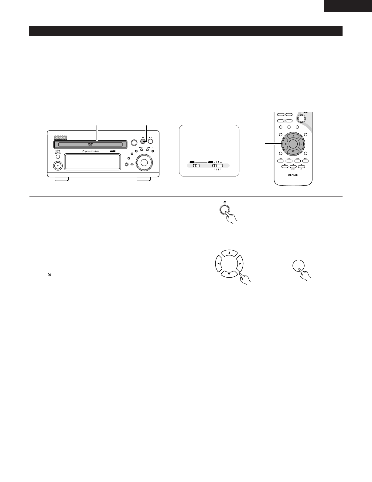
(7) Playing still picture files (JPEG format)
ENTER
B
BAND
PHONES
VOLUME
ON / STANDBY
DVD SURROUND RECEIVER ADV-M71
TONE/SDB
FUNCTION
MENU/SET
+
-
SURROUND/ SELECT
PUSH - PARAM.
VIRTUAL SPEAKER
11
RC-936
3
STATUS
RETURN
ANGLE AUDIO
SUB TITLE
SETUP TONE/SDB
ENTER
MUTING
DISPLAY MENU
TOP MENU
SURROUND
PARAME TER
CH SELECT
-
+
VCR CH
9
8
76
-
1
-w
A / V
SYSTEM MD
CDR TAPE
TUNER TV / VCR
IN/SURR.
IN/SURR.
DVD
2 JPEG files stored on Kodak picture CDs, CD-Rs and CD-RWs can be played as a slide show and enjoyed on the ADV-M71.
[1] Playing Kodak picture CDs/FUJICOLOR CDs
2 Playing Picture CDs and Fujicolor CDs
The ADV-M71 can play Kodak Picture CDs and Fuji Film Fujicolor CDs, so you can view the photographs stored on them on a TV screen.
(Picture CDs and Fujicolor CDs are CDs containing photographs taken on conventional silver film cameras which have been converted into
digital data. For details on Picture CDs, please contact a store providing Kodak development services. For details on Fujicolor CDs, please
contact a store providing Fuji Film development services.)
Set the remote
control selector
switches to A/V
and DVD.
ENGLISH
Load the Picture CDs or Fujicolor CDs into the set.
1
• For Picture CDs:
Playback of the still pictures starts automatically when the disc is
loaded.
• For Fujicolor CDs:
When the disc is loaded, up to 9 photos are automatically
displayed on the screen. Use the remote control unit’s cursor
buttons (0, 1, • and ª) to select the photo you want to play, then
press the ENTER button to start playback.
Press the stop button to stop playback.
• “KODAK” is the registered trademark of Eastman kodak Co.
• “FUJICOLOR CD” is the registered trademark of Fuji Photo Film Co.,Ltd.
Main unit
For Fujicolor CDs:
\
Main unit Remote control unit
75
Page 76
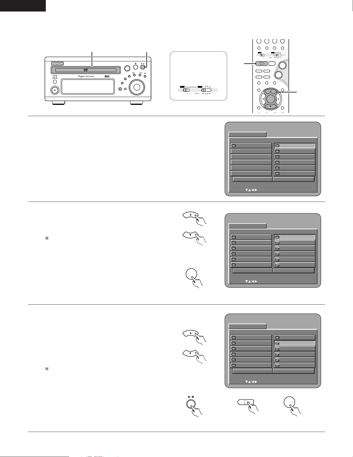
ENGLISH
DI SC INFORMATION
SINGLE:
DECISION : ENTER BUTTON
0••
1A
2B
3C
4D
5E
JPEG 1
JPEG 2
JPEG 3
JPEG 4
JPEG 5
ROOT
PLAY MODE FOLDER
SIGNAL ELAPSED : --:--
B
ENTER
DI SC INFORMATION
SINGLE:
DECISION : ENTER BUTTON
0••
1A
2B
3C
4D
5E
JPEG 1
JPEG 2
JPEG 3
JPEG 4
JPEG 5
ROOT
PLAY MODE FOLDER
SIGNAL ELAPSED : --:--
B
DVD
1
ENTER
B
BAND
PHONES
VOLUME
ON / STANDBY
DVD SURROUND RECEIVER ADV-M71
TONE/SDB
FUNCTION
MENU/SET
+
-
SURROUND/ SELECT
PUSH - PARAM.
VIRTUAL SPEAKER
13
-
A / V
3
STATUS
SETUP TONE/SDB
FUNCTIONSURROUNDINPUT MODETEST TONE
DVD
0
/
10
CALL
ENTER
MUTING
+
10
SYSTEM MD
CDR TAPE
TUNER TV / VCR
SURROUND
PARAMETER
CH SELECT
-
+
VCR CH
IN/SURR.
IN/SURR.
DVD
9
8
21
76
+
-
2,3
3
DI SC INFORMATION
SINGLE:
DECISION : ENTER BUTTON
0ROOT
1JPEG 1
2JPEG 2
3JPEG 3
4JPEG 4
5JPEG 5
ROOT
PLAY MODE FOLDER
SIGNAL ELAPSED : --:--
B
A / V
SYSTEM MD
CDR TAPE
TUNER TV / VCR
IN/SURR.
IN/SURR.
DVD
[2] Playing still pictures stored on CD-Rs/RWs
Load the CD-R/RW on which the still pictures have
1
been written into the ADV-M71.
• When the disc is loaded in the ADV-M71, the disc
information screen appears.
• If there are multiple folders, proceed to step 2.
• If there are no folders on the disc, proceed to step 3.
Set the remote
control selector
switches to A/V
and DVD.
Use the •and ªcursor buttons to select the folder
2
containing the file(s) you want to play, then press the
ENTER button.
To change the folder
Use the •cursor button to select “ROOT” at the
upper right of the screen, then press the ENTER
button. The screen in step 1 reappears. Select the
desired folder.
Use the •and ªcursor buttons on the remote control
3
unit to select the still picture file from which you want
to start the slide show, then press the PLAY button or
the ENTER button on the remote control unit.
• The slide show starts.
• Only the still picture files in the selected folder are
played.
Once all the still picture files in the folder have been
played, the disc information screen reappears.
76
Remote control unit
Remote control unit
Remote control unit
Main unit
Remote control unit
Page 77
ENGLISH
To view several of the still pictures stored on the disc at once:
• Press the STOP button to display up to 9 still pictures at once.
• To select and view a still picture (to start the slide show from a specific still picture), use the cursor buttons (ª, •,
desired still picture, then press the ENTER button.
To temporarily stop the slide show:
• Press the PAUSE button.
• To resume the slide show, press the PLAY button.
To cue a still picture you want to view (from which you want to start the slide show):
• During the slide show, press one of the SKIP (
SKIP 9button to cue ahead to the next still picture.
Flipping and rotating still pictures:
• Use the cursor buttons (ª, •,
cursor button: The currently displayed still picture is flipped vertically.
•
cursor button: The currently displayed still picture is flipped horizontally.
ª
0
cursor button: The currently displayed still picture is rotate 90° counterclockwise.
1
cursor button: The currently displayed still picture is rotate 90° clockwise.
Play the image in the zoom mode.
• When the ZOOM button is pressed while playing a JPEG image (“ZOOM ON” is displayed on the screen at this time) zoom in and zoom
out using the search keys.
(6: zoom out, 7: zoom in)
• When the image is zoomed, use the cursor buttons (ª, •,
• Continuous playback (SLIDE SHOW) is not possible in the zoom mode.
The way of switching to the next image during continuous JPEG image playback (SLIDE SHOW) can be selected.
• Press the SLIDE MODE button on the remote control unit.
• Select from SLIDE SHOW MODE 1 to MODE 11, MODE RAND and MODE NONE.
0
and 1) to flip the still picture.
8,9
) buttons. Press the SKIP 8button to cue back to the previous still picture, the
0
and 1) to move the zoomed picture.
0
and 1) to select the
Special play modes for MP3/WMA and JPEG files
Use the 0 and 1 cursor buttons to select the play mode, the • and ª cursor buttons to select the special play mode.
• FOLDER (the MP3/WMA and JPEG files in the folder are played in order starting from the selected file)
• FOLDER REPEAT (all the MP3/WMA and JPEG files in the folder are played repeatedly starting from the selected file)
• DISC (all the MP3/WMA and JPEG files on the disc are played in order starting from the selected file)
• DISC REPEAT (all the MP3/WMA and JPEG files on the disc are played repeatedly starting from the selected file)
• RANDOM ON (all the MP3/WMA and JPEG files in the folder are played in random order starting from the selected file)
• TRACK REPEAT (the select MP3/WMA or JPEG file is played repeatedly)
NOTES:
• The ADV-M71 is compatible with image data stored in JPEG format, but Denon does not guarantee that all image data stored in JPEG
format can be viewed.
• Pictures with resolutions of up to 2048 x 1536 pixels can be displayed.
• It may not be possible to play some CD-Rs/RWs due to disc properties, dirt, scratches, etc.
• When storing JPEG files on the CD-R/RW, set the writing program to store the files in the “ISO9660 level 1” format.
• Be sure to give JPEG files the extension “.JPG” and “.JPE”. Files with other extensions or with no extensions cannot be viewed on the
ADV-M71.
• Do not apply stickers, tape, etc., to either the label side or the signal side of CD-R/RW discs. If adhesive gets on the surface of a disc,
the disc may get stuck inside the ADV-M71 and be impossible to eject.
• Do not play CD-R/RW discs containing any files other than music CD files (in CDA format), MP3/WMA and JPEG files. Doing so may
result in malfunction or damage, depending on the type of file.
• JPEG files written using Macintosh computers cannot be played.
77
Page 78
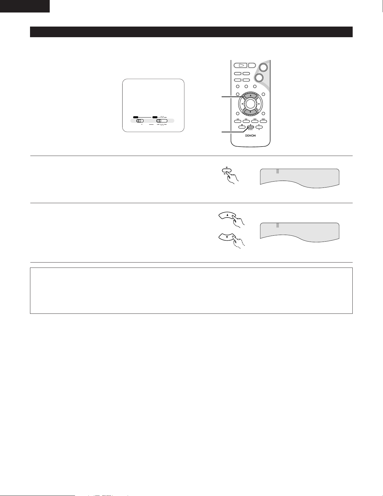
ENGLISH
AUDIO
RC-936
3
STATUS
RETURN
ANGLE AUDIO
SUB TITLE
SETUP TONE/SDB
DVD
ENTER
MUTING
DISPLAY MENU
TOP MENU
CDR TAPE
SURROUND
PARAMETER
CH SELECT
-
+
VCR CH
9
8
21
76
+
-
1
2
A / V
SYSTEM MD
CDR TAPE
TUNER TV / VCR
IN/SURR.
IN/SURR.
DVD
(8) Using the Multiple Audio, Subtitle and Angle Functions
[1] Switching the Audio Language (Multiple Audio Function)
2 With DVDs containing multiple audio language signals, the audio language can be switched during playback.
Set the remote
control selector
switches to A/V
and DVD.
During playback, press the AUDIO button.
1
• The current audio language number is displayed.
AUDIO 1/3:DOLBY D3/2/.1 ENG
Remote control unit
Use the • and ª cursor buttons to select the desired
2
language.
• The display turns off when the AUDIO button is pressed.
AUDIO 2/3:DOLBY D3/2/.1 FRA
Remote control unit
NOTES:
• With some discs it is not possible to change the audio language during playback. In such cases, select from the DVD menu. (See page
93.)
• If the desired language is not set after pressing the
• and ª
cursor buttons several times, the disc does not include that language.
• The language selected in the default settings is set when the power is turned on and when the disc is replaced.
78
Page 79
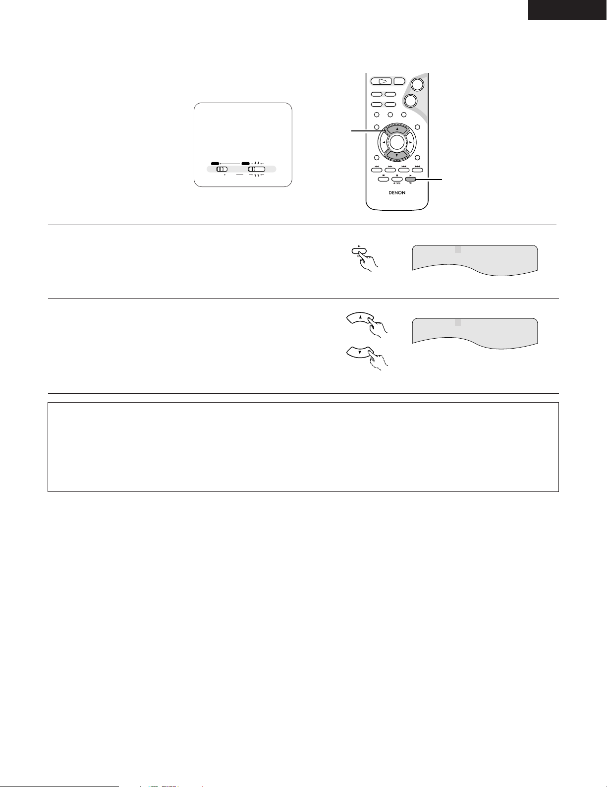
[2] Switching the Subtitle Language (Multiple Subtitle Function)
SUB TITLE
RC-936
3
STATUS
RETURN
ANGLE AUDIO
SUB TITLE
SETUP TONE/SDB
DVD
ENTER
MUTING
DISPLAY MENU
TOP MENU
CDR TAPE
SURROUND
PARAMETER
CH SELECT
-
+
VCR CH
9
8
21
76
+
-
1
2
A / V
SYSTEM MD
CDR TAPE
TUNER TV / VCR
IN/SURR.
IN/SURR.
DVD
2 With DVDs containing multiple subtitle language signals, the subtitle language can be switched during playback.
Set the remote
control selector
switches to A/V
and DVD.
During playback, press the SUBTITLE button.
1
• The current subtitle language number is displayed.
Remote control unit
SUBTITLE 01/03:ENG
ENGLISH
Use the • and ª cursor buttons to select the desired
2
language.
SUBTITLE 02/03:FRA
• The display turns off when the SUBTITLE button is
pressed.
Remote control unit
NOTES:
• If the desired language is not set after pressing the
• and ª
cursor buttons several times, the disc does not include that language.
• The subtitle language set with the default settings is set when the power is turned on and when the disc is replaced. If that language is
not included on the disc, the disc’s default language is set.
• When the subtitle language is changed, several seconds may be required for the new language to appear.
• When a disc supporting the closed caption is played, the subtitle and the closed caption may overlap each other on the TV monitor. In
this case, turn the subtitle off.
79
Page 80
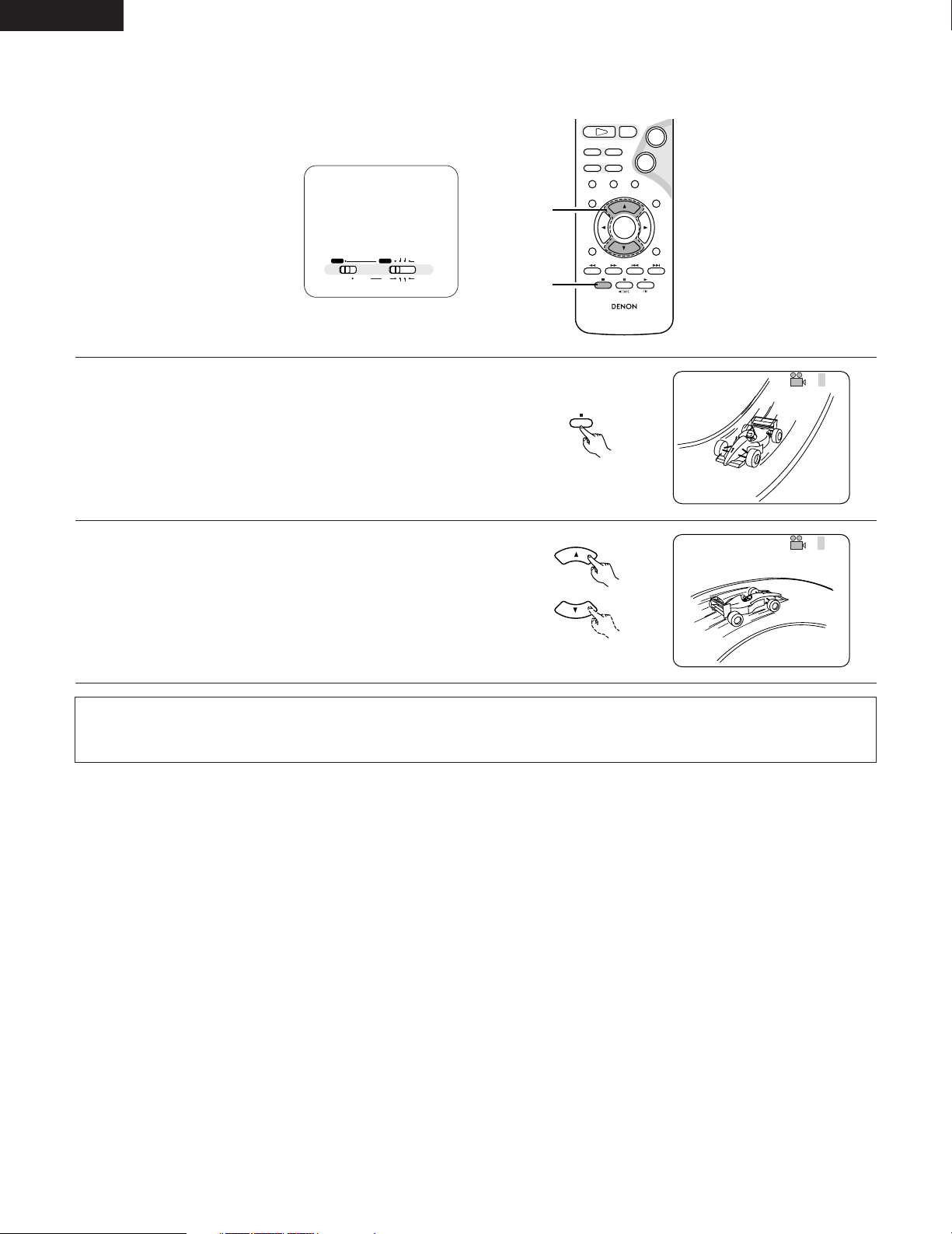
ENGLISH
ANGLE
4/5
RC-936
3
STATUS
RETURN
ANGLE AUDIO
SUB TITLE
SETUP TONE/SDB
DVD
ENTER
MUTING
DISPLAY MENU
TOP MENU
CDR TAPE
SURROUND
PARAMETER
CH SELECT
-
+
VCR CH
9
8
21
76
+
-
1
2
A / V
SYSTEM MD
CDR TAPE
TUNER TV / VCR
IN/SURR.
IN/SURR.
DVD
[3] Switching the Angle (Multiple Angle Function)
2 With DVDs containing multiple angle signals, the angle can be switched during playback.
Set the remote
control selector
switches to A/V
and DVD.
During playback, press the ANGLE button.
1
• The current angle number is displayed.
Remote control unit
Use the • and ª cursor buttons to select the desired angle.
2
• The display turns off when the ANGLE button is pressed.
Remote control unit
NOTES:
• The multiple angle function only works with discs on which multiple angles are recorded.
• At scenes where multiple angles are recorded, the angle can be switched.
3/5
80
Page 81
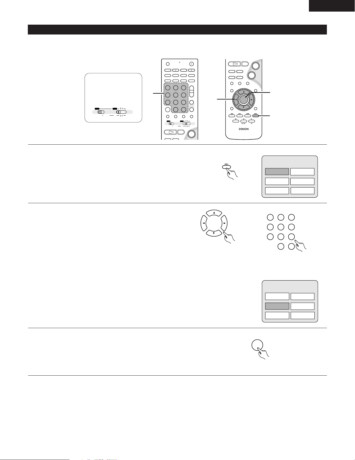
(9) Using the Menus
ENTER
TOP MENU
321
654
987
0
/
10
+
10
TUNERDVD
MD/LINE-1
TAPE/LINE-2
AUTO DECODE
VIRTUAL
5CH STEREO
STEREO
D.AUX
+
-
+
-
A / V
A-B REPEAT
SEARCH MODE
ONOFF
REPEAT RANDOM
CLEAR ZOOMSLIDE MODE
PROG/DIRECT
MEMO BANDMODE
FUNCTIONSURROUNDINPUT MODETEST TONE
DVD
TUNER
CH
3
-
+
21
654
987
0
/
10
CALL
+
10
SYSTEM MD
CDR TAPE
TUNER TV / VCR
VCR
NTSC/PAL
SLEEP
ENTER
CD SRS
EDIT/MENUCHARAC.
REC
TIMETITLE
TUNING /
TV VOL
TV CH TV CH
TUNERDVD
MD/LINE-1
TAPE/LINE-2
AUTO DECODE
VIRTUALDIRECT
5CH STEREO
STEREO
D.AUX
IN/SURR.
IN/SURR.
DVD
T VT V INSOURCE
21
+
2
RC-936
3
STATUS
RETURN
ANGLE AUDIO
SUB TITLE
SETUP TONE/SDB
DVD
ENTER
MUTING
DISPLAY MENU
TOP MENU
CDR TAPE
SURROUND
PARAMETER
CH SELECT
-
+
VCR CH
9
8
21
76
+
-
1
2
3
A / V
SYSTEM MD
CDR TAPE
TUNER TV / VCR
IN/SURR.
IN/SURR.
DVD
[1] Using the Top Menu
2 For DVDs containing multiple titles, the desired title can be selected and played from the top menu.
Set the remote
control selector
switches to A/V
and DVD.
ENGLISH
During playback, press the TOP MENU button.
1
• The top menu appears.
Use the cursor or number buttons to select the desired title.
2
• If you select the title number using the number buttons, skip step
3 below.
Remote control unit
Remote control unit
Example:
TOP MENU
Apple
Orange
Peach
Remote control unit
Example:
When “Orange” is selected
Banana
Strawberry
Pineapple
TOP MENU
Apple
Orange
Peach
Banana
Strawberry
Pineapple
Press the ENTER button.
3
• Playback starts.
• Playback also starts if the PLAY (
1) button is pressed.
Remote control unit
81
Page 82
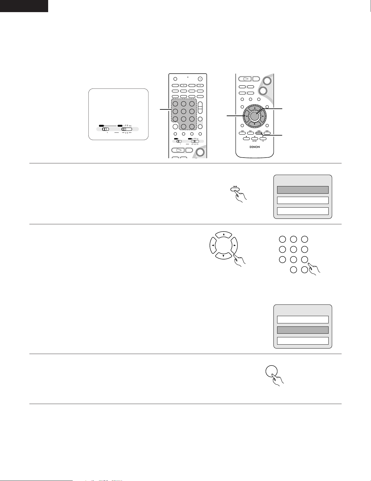
ENGLISH
ENTER
MENU
321
654
987
0
/
10
+
10
TUNERDVD
MD/LINE-1
TAPE/LINE-2
AUTO DECODE
VIRTUAL
5CH STEREO
STEREO
D.AUX
+
-
+
-
A / V
A-B REPEAT
SEARCH MODE
ONOFF
REPEAT RANDOM
CLEAR ZOOMSLIDE MODE
PROG/DIRECT
MEMO BANDMODE
FUNCTIONSURROUNDINPUT MODETEST TONE
DVD
TUNER
CH
3
-
+
21
654
987
0
/
10
CALL
+
10
SYSTEM MD
CDR TAPE
TUNER TV / VCR
VCR
NTSC/PAL
SLEEP
ENTER
CD SRS
EDIT/MENUCHARAC.
REC
TIMETITLE
TUNING /
TV VOL
TV CH TV CH
TUNERDVD
MD/LINE-1
TAPE/LINE-2
AUTO DECODE
VIRTUALDIRECT
5CH STEREO
STEREO
D.AUX
IN/SURR.
IN/SURR.
DVD
T VT V INSOURCE
21
+
2
RC-936
3
STATUS
RETURN
ANGLE AUDIO
SUB TITLE
SETUP TONE/SDB
DVD
ENTER
MUTING
DISPLAY MENU
TOP MENU
CDR TAPE
SURROUND
PARAMETER
CH SELECT
-
+
VCR CH
9
8
21
76
+
-
1
2
3
A / V
SYSTEM MD
CDR TAPE
TUNER TV / VCR
IN/SURR.
IN/SURR.
DVD
[2] Using the DVD Menu
2 Some DVDs include special menus called DVD menus.
For example, DVDs with complex contents may contain guide menus, and DVDs with multiple languages may contain audio and subtitle
language menus.
These menus are called “DVD menus”.
Here we describe the general procedure for using DVD menus.
Set the remote
control selector
switches to A/V
and DVD.
During playback, press the MENU button.
1
• The DVD menu appears.
Use the cursor or number buttons to select the desired item.
2
• If you select the item using the number buttons, skip step 3
below.
Remote control unit
Remote control unit
Example:
DVD MENU
1. SUB TITLE
2. AUDIO
3. ANGLE
Remote control unit
Example:
“AUDIO” is selected
DVD MENU
1. SUB TITLE
2. AUDIO
3. ANGLE
Press the ENTER button.
3
• The selected item is set.
• If more menus appear, repeat steps 2 and 3.
82
Remote control unit
Page 83
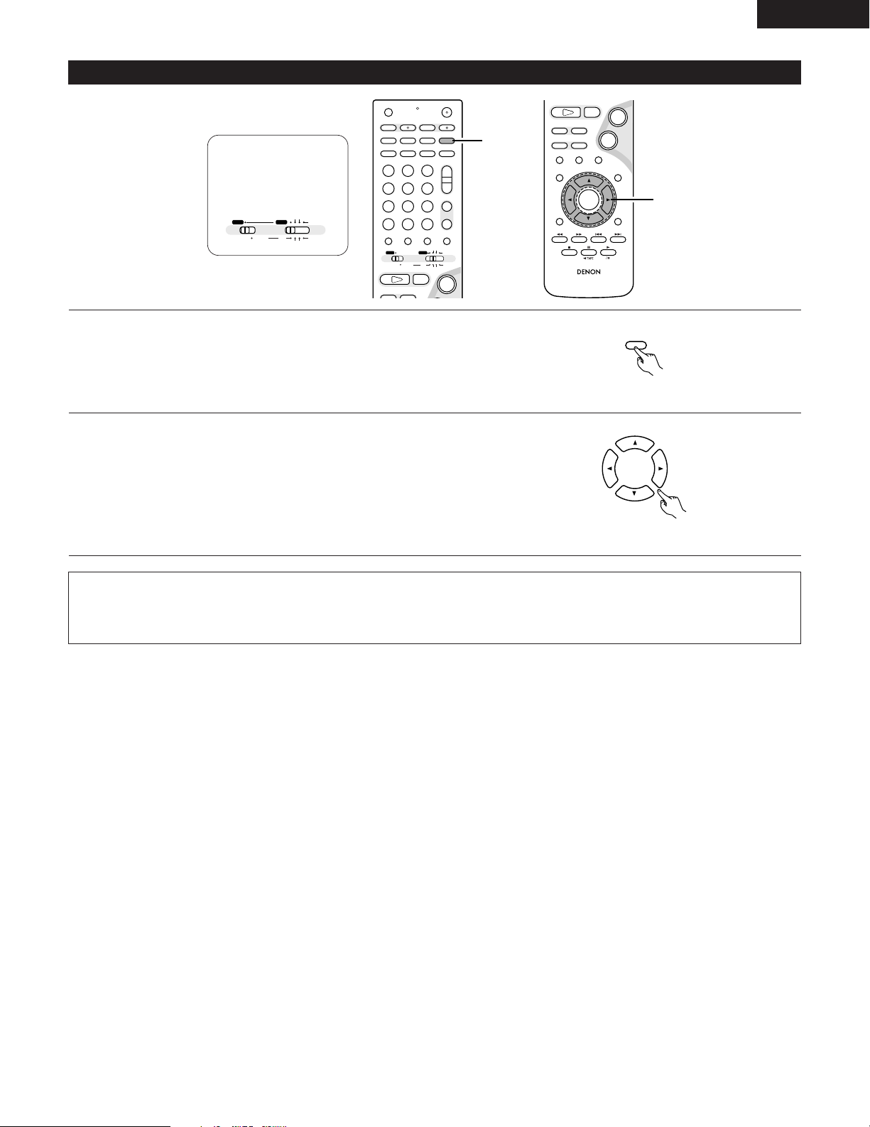
ZOOM
+
EDIT/MENU
TV CH
(10) Playing in the zoom mode
+
-
+
-
A / V
A-B REPEAT
SEARCH MODE
ONOFF
REPEAT RANDOM
CLEAR ZOOMSLIDE MODE
PROG/DIRECT
MEMO BANDMODE
FUNCTIONSURROUNDINPUT MODETEST TONE
DVD
TUNER
CH
3
-
+
21
654
987
0
/
10
CALL
+
10
SYSTEM MD
CDR TAPE
TUNER TV / VCR
VCR
NTSC/PAL
SLEEP
ENTER
CD SRS
EDIT/MENUCHARAC.
REC
TIMETITLE
TUNING /
TV VOL
TV CH TV CH
TUNERDVD
MD/LINE-1
TAPE/LINE-2
AUTO DECODE
VIRTUALDIRECT
5CH STEREO
STEREO
D.AUX
IN/SURR.
IN/SURR.
DVD
T VT V INSOURCE
21
+
1
RC-936
3
STATUS
RETURN
ANGLE AUDIO
SUB TITLE
SETUP TONE/SDB
DVD
ENTER
MUTING
DISPLAY MENU
TOP MENU
CDR TAPE
SURROUND
PARAMETER
CH SELECT
-
+
VCR CH
9
8
21
76
+
-
2
A / V
SYSTEM MD
CDR TAPE
TUNER TV / VCR
IN/SURR.
IN/SURR.
DVD
Set the remote
control selector
switches to A/V
and DVD.
In the play or pause mode, press the ZOOM button.
1
• The zoom rate increases each time the ZOOM button is pressed.
For DVD video discs and video CDs:
OFF Æ x1.5 Æ x2 Æ x4 Æ OFF
Use the cursor buttons (ª, •, 0 and 1) to move the zoomed
2
picture.
ENGLISH
Remote control unit
NOTES:
• Zooming is not possible with some discs.
• The zoom function may not work properly at some scenes.
• Zooming is not possible at the top menu or the menu screen.
Remote control unit
83
Page 84
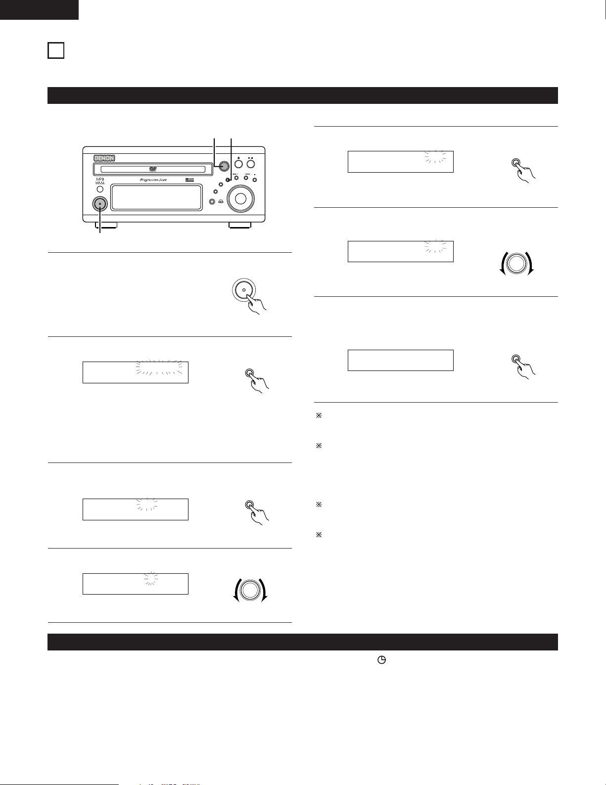
ENGLISH
MENU/ SET
Time AM12:00
Adj AM12:00
MENU/ SET
Adj PM 7:30
SURROUND/ SELECT
PUSH - PARAM.
Time PM 7:30
MENU/ SET
B
BAND
PHONES
VOLUME
ON / STANDBY
DVD SURROUND RECEIVER ADV-M71
TONE/SDB
FUNCTION
MENU/SET
+
-
SURROUND/ SELECT
PUSH - PARAM.
VIRTUAL SPEAKER
1
4,6
2,3,5,7
Adj PM 7:00
SURROUND/ SELECT
PUSH - PARAM.
MENU/ SET
Adj PM 7:00
ON / STANDBY
18
USING THE TIMER
2 Timer and system operations are possible once the setup procedure has been completed.
(1) Setting the clock (12-hour display)
Example: Setting the current time to “7:30 p.m.”
Turn on the power.
1
Press the MENU/SET button.
5
Turn the SURROUND/SELECT knob to move to the minutes
6
position.
Main unit
Main unit
Press the MENU/SET button to display “Tim e”.
2
• If the time has not yet been set or if there has been a
power shortage, the time display flashes.
• If the time has been set, the current time is displayed.
Press the MENU/SET button and hold it in for over 2 seconds.
3
• The hours position flashes.
Turn the SURROUND/SELECT knob to set the hours.
4
Main unit
Main unit
Main unit
Press the MENU/SET button at the sound of a time signal,
etc.
7
• The “30” in the minutes place stops flashing and the
current time is displayed.
Main unit
To check the current time when the regular display is displayed,
press the MENU/SET button once. The current time remains
displayed until some other operation is performed.
The time can be displayed by pressing the MENU/SET button
when the power is in the standby mode. (When this is done, the
set is no longer in the low power consumption standby mode.)
When pressed twice while the time is displayed, the display turns
off and the set is put back in the low power consumption standby
mode.
The current time can also be set when the power is in the standby
mode by pressing the MENU/SET button to display the time then
performing steps 3 to 7.
The clock runs by synchronizing with the power supply frequency.
The time may be off by 2 to 3 minutes per month. If so, reset the
time.
Before setting the timer
2 Be sure to set the current time. If the current time is not set, the timer standby indicator does not light and the timer will not function.
2 Be sure to preset the broadcast station before setting the timer. (See page 63.).
2 Everyday timer: The power is switched on and off (standby) once at the same time each day.
Once timer: The power is switched on and off (standby) at the specified time once only.
Sleep timer: The power can be set to turn off in 120 minutes, 90 minutes, or between 60 and 10 minutes in 10 minute steps.
2 If the times set for the everyday timer, once timer and sleep timer overlap, the sleep timer has priority. The once time has priority if the everyday
timer and once timer times overlap.
2 It is not possible to set the timer start and stop times to the same time.
84
Main unit
Page 85
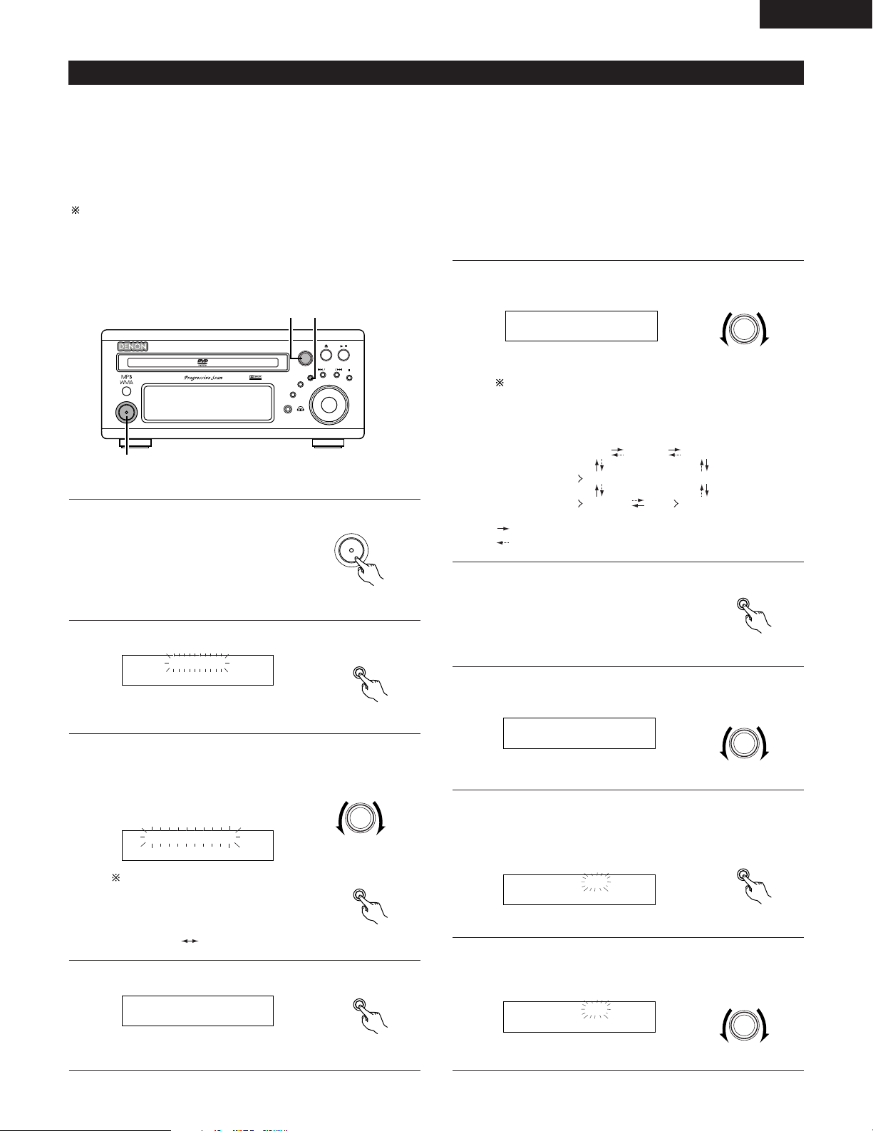
ENGLISH
B
BAND
PHONES
VOLUME
ON / STANDBY
DVD SURROUND RECEIVER ADV-M71
TONE/SDB
FUNCTION
MENU/SET
+
-
SURROUND/ SELECT
PUSH - PARAM.
VIRTUAL SPEAKER
1,18
2,3,4,6,8,
10,12,14,16
3,5,7,9,11,
13,15,17
MENU/ SET
TIMER
EVERYDAY
SURROUND/ SELECT
PUSH - PARAM.
E FUNC
MENU/ SET
ON / STANDBY
MENU/ SET
SURROUND/ SELECT
PUSH - PARAM.
E TUNER
DVD TUNER (LINE1)
(LINE2)
(LINE1)
TU
AUX (LINE1 2)
TU (LINE2)
*
*
*
**
MENU/ SET
P03 FM 92.50M
SURROUND/ SELECT
PUSH - PARAM.
E on AM12:00
MENU/ SET
E on PM12:00
SURROUND/ SELECT
PUSH - PARAM.
ONCE
EVERYDAY
(2) Setting the everyday timer and once timer
2 Be sure to set the current time before setting the timer. (See page 84.)
2 Use the everyday timer to switch the power on and off (standby) once at the same time each day.
Use the once timer to switch the power on and off (standby) at the specified time once only.
2 With the ADV-M71 it is possible to play the tuner, a DVD or a CD with the timer.
2 It is possible to play a DVD, CD, tape, the tuner, MD or the device connected to the AUX terminals with the timer and to record the tuner or
the device connected to the AUX terminals onto an MD recorder or cassette deck using the timer.
Timer playback is not possible for some DVDs. (Most DVDs stop at the menu screen.)
Example 1: Listening to preset station “3” (FM 92.5 MHz) from p.m.12:35 to p.m.12:56 with the everyday timer
Turn the SURROUND/SELECT knob and set the function to
5
“TUNER”.
Main unit
The function switches as shown below each time the
surround button is pressed.
Functions marked “*” differ according to whether “LINE1” or “LINE-2” is set.
Turn on the power.
1
Press the MENU/SET button to display “TIMER”.
2
Turn the SURROUND/SELECT knob to display “EVERYDAY”,
3
then press the MENU/SET button.
• The display switches as follows
each time the SURROUND/SELECT
knob is turned:
The display switches as follows
each time the
SURROUND/SELECT knob is
turned:
Press the MENU/SET button.
4
Main unit
Main unit
Main unit
Main unit
Main unit
or
:Clockwise turn
:Counterclockwise turn
Press the MENU/SET button.
6
Turn the SURROUND/SELECT knob and select preset number
7
“P03”.
Press the MENU/SET button.
8
• The data for the selected station is stored in the memory
and the unit is set to the timer start time setting mode.
•“E” and “on” are displayed.
<Setting the timer start time>
9
Turn the SURROUND/SELECT knob to set the hours place to
“PM12”.
Main unit
Main unit
Main unit
Main unit
85
Page 86
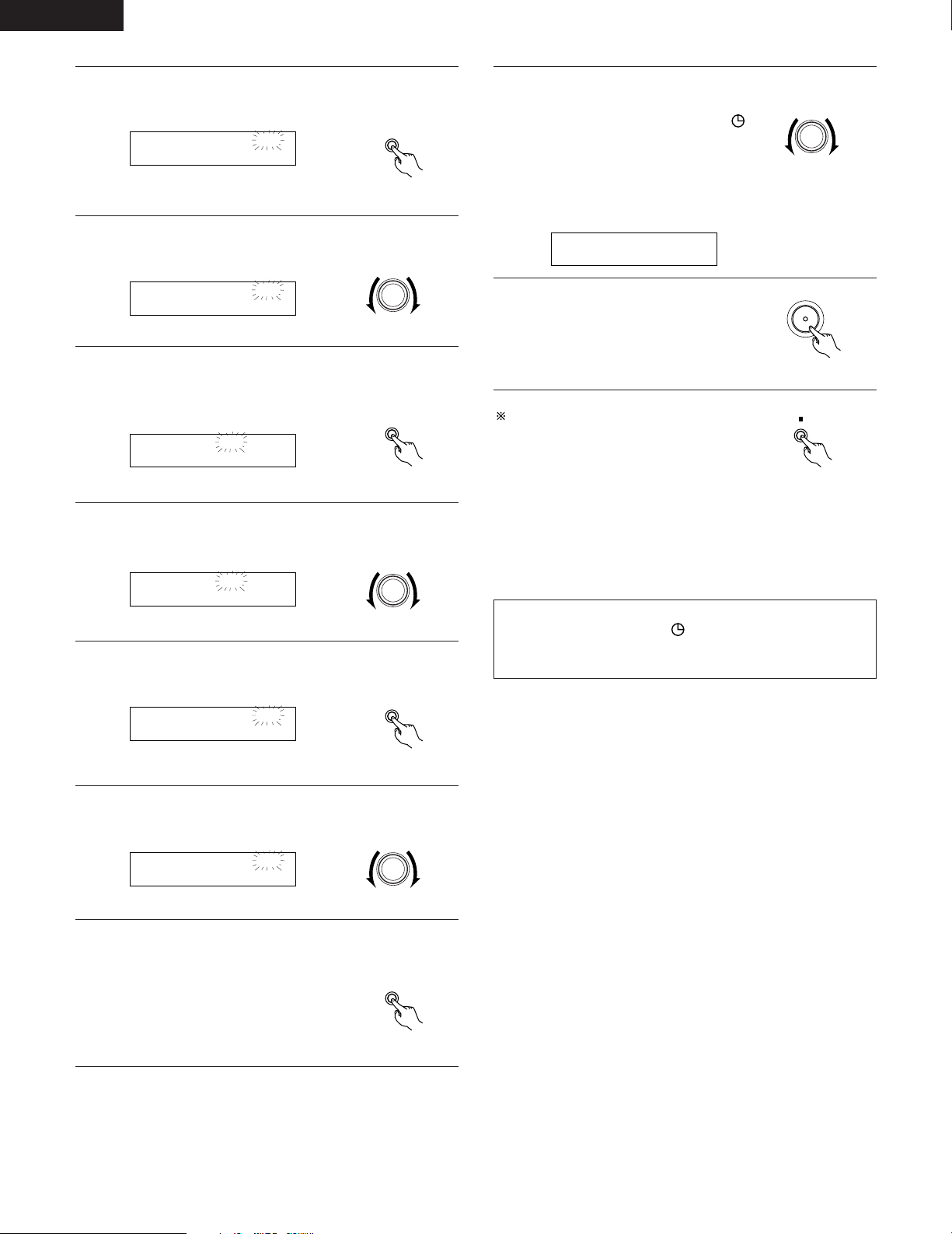
ENGLISH
MENU/ SET
E on PM12:00
E on PM12:35
SURROUND/ SELECT
PUSH - PARAM.
MENU/ SET
E offAM12:00
E offPM12:00
SURROUND/ SELECT
PUSH - PARAM.
MENU/ SET
E offPM12:00
E offPM12:56
SURROUND/ SELECT
PUSH - PARAM.
MENU/ SET
SURROUND/ SELECT
PUSH - PARAM.
1 off/E on
ON / STANDBY
BAND
Press the MENU/SET button.
10
• The “PM12” in the hours place is stored in the memory.
Turn the SURROUND/SELECT knob and set the minutes
11
place to “35”.
Press the MENU/SET button.
12
• The start time is stored in the memory and the unit is set
to the timer stop time setting mode.
•“E” and “off” light.
<Setting the timer stop time>
13
Turn the SURROUND/SELECT knob to set the hours place to
“PM12”.
Main unit
Main unit
Main unit
Turn the SURROUND/SELECT knob to display “Eon”.
17
• The everyday timer is turned on and
the timer standby indicator
lights. This completes the setting of
the timer.
For more details, see “Turning the
everyday timer and once timer on
and off” on page 85.
Turn off the power.
18
• The standby mode is set.
(The power indicator turns orange.)
• When the timer start time is
reached, the timer operates.
If you make a mistake when setting the
timer
• Press the stop button at any point
between steps 4 and 15. (The display
returns to as it was in step 3.)
• Press the MENU/SET button repeatedly
to display the item you want to correct,
then correct the item.
• After correcting the item, press the MENU/SET button again
repeatedly to proceed to step 18 and complete the setting of the
timer.
Main unit
Main unit
Main unit
Press the MENU/SET button.
14
• The “PM12” in the hours place is stored in the memory.
Turn the SURROUND/SELECT knob and set the minutes
15
place to “56”.
Press the MENU/SET button.
16
• The stop time is stored in the memory.
Main unit
Main unit
Main unit
Main unit
NOTE:
• The timer standby indicator does not light if the current time
has not been set. Set the current time before setting the timer.
(See page 84.)
86
Page 87
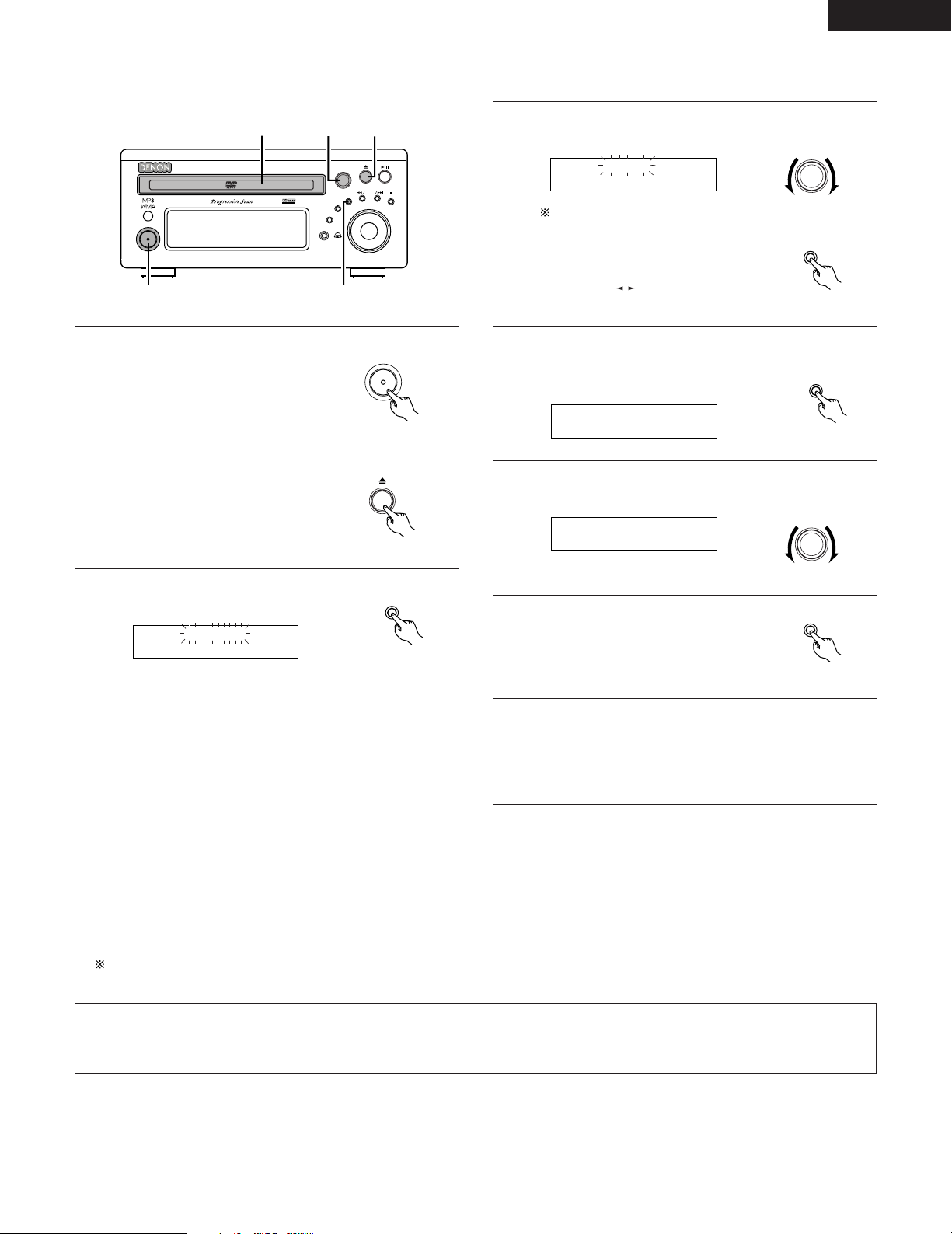
Example 2: Listening to a CD with the once timer
B
BAND
PHONES
VOLUME
ON / STANDBY
DVD SURROUND RECEIVER ADV-M71
TONE/SDB
FUNCTION
MENU/SET
+
-
SURROUND/ SELECT
PUSH - PARAM.
VIRTUAL SPEAKER
1
3,4,5,7
4,6
22
ON / STANDBY
SURROUND/ SELECT
PUSH - PARAM.
ONCE
MENU/ SET
TIMER
1 FUNC
MENU/ SET
1DVD
SURROUND/ SELECT
PUSH - PARAM.
MENU/ SET
ONCE
EVERYDAY
MENU/ SET
Turn the SURROUND/SELECT knob to display “ONCE”, then
4
press the MENU/SET button.
ENGLISH
Turn on the power.
1
Open the disc holder, load the CD,
2
then close the disc holder.
Press the MENU/SET button to
3
display “TIMER”.
Main unit
Main unit
Main unit
The display switches as follows
each time the
SURROUND/SELECT knob is
turned:
Press the MENU/SET button.
5
• The once timer time setting mode is set.
•“1” (once) lights.
Turn the SURROUND/SELECT knob and set the function to
6
“DVD”.
Press the MENU/SET button.
7
• Timer function, “DVD”, is stored in
the memory.
Main unit
Main unit
Main unit
Main unit
Main unit
2 Timer playback and recording can be performed when system connections are made between the ADV-M71 and the D-M31 series cassette
Now follow steps 9 to 18 under “Setting the everyday timer
8
and once timer” (pages 85 and 86).
•“1” and “on” light when setting the start time.
“1” and “off” light when setting the stop time.
• Turn the once timer on at step 17.
deck (DRR-M31). (Both the everyday and once timer can be used.)
• Timer playback of the cassette deck (when TAPE is set for LINE-2)
• Timer playback of the device connected to the AUX input terminals (when AUX is set for LINE-1 or LINE-2)
• Timer recording of radio programs from the ADV-M71 onto the cassette deck (when TAPE is set for LINE-1)
• Timer recording from the device connected to the AUX input terminals onto the cassette deck (when AUX is set for LINE-1 and TAPE is set
for LINE-2)
Timer recording onto the device connected to the AUX input terminals is not possible. The timer function changes automatically according
to the function set for LINE-1 and LINE-2.
NOTE:
• For timer recording and playback using the device connected to the AUX input terminals, note that the ADV-M71 cannot control the power
of the device or playback operations on it. Make the settings accordingly.
87
Page 88
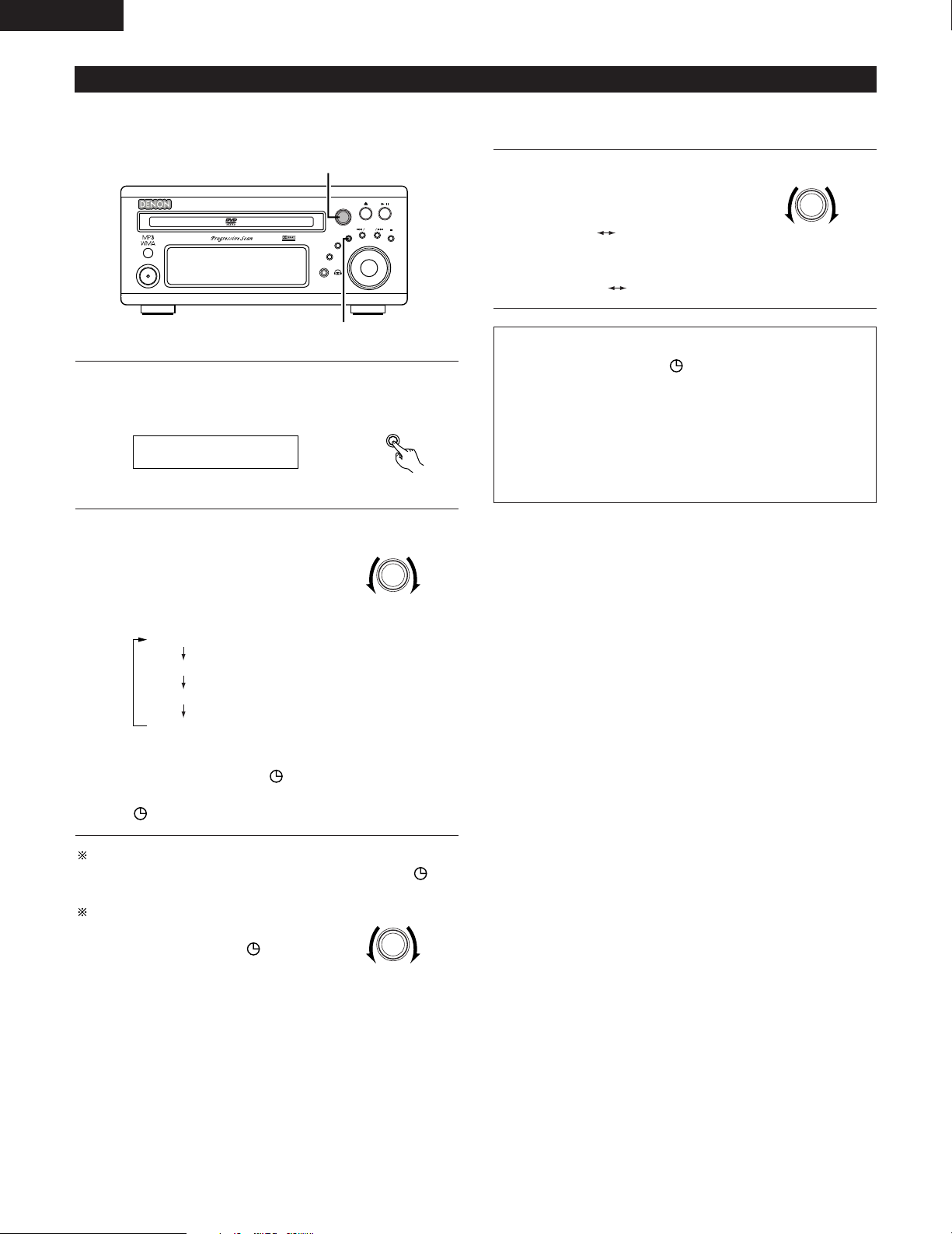
ENGLISH
B
BAND
PHONES
VOLUME
ON / STANDBY
DVD SURROUND RECEIVER ADV-M71
TONE/SDB
FUNCTION
MENU/SET
+
-
SURROUND/ SELECT
PUSH - PARAM.
VIRTUAL SPEAKER
1
2
MENU/ SET
1 on/E on
1 on/E on
1 on/E off
1 off/E on
1 off/E off
SURROUND/ SELECT
PUSH - PARAM.
SURROUND/ SELECT
PUSH - PARAM.
SURROUND/ SELECT
PUSH - PARAM.
1on/E off f1off/E of
1off/E on f1off/E of
(3) Turning the everyday timer and once timer on and off
• After the timer has been set using the procedure described under “(2) Setting the everyday timer and once timer” (pages 85 to 86), turn the
everyday timer and/or once timer on so that the set operations will be performed.
• If only the once timer is set, the setting
changes as shown below each time the
SURROUND/SELECT knob is turned.
• If only the everyday timer is set, the setting changes as follows:
NOTES:
Press the MENU/SET button to set the timer standby setting
1
mode.
• The current settings are displayed.
Main unit
• The timer standby indicator does not light if the current time
has not been set. Set the current time before setting the timer.
(See page 84.)
• If the times set for the everyday timer and once timer overlap,
the once time has priority.
• Be sure to set the power to the standby mode when you want
the timer to operate.
Main unit
Turn the SURROUND/SELECT knob and select the timer to be
operated.
2
• The display switches as follows
each time the
SURROUND/SELECT knob is
turned:
Both the once timer and everyday
timer are activated.
Only the everyday timer is activated.
Only the once timer is activated.
Neither the once timer nor the
everyday timer are activated.
Main unit
• When either the once or everyday timer is activated, the
timer standby indicator lights. The display returns to
normal about 4 seconds after the timer standby indicator
is displayed.
The timer operation is performed when the SURROUND/SELECT
knob has been turned and the timer standby indicator has
been lit.
If you do not want the timer to operate,
turn the SURROUND/SELECT knob to turn
the timer standby indicator off.
88
Main unit
Page 89

(4) Everyday timer and once timer priority
• If the times set for the everyday timer and once timer overlap, the once time has priority.
(5) About the everyday timer and once timer
2 Checking the timer settings
• Use the same procedure as when setting the timer to check the timer settings.
q Press the MENU/SET button to display “TIMER”.
w Turn the SURROUND/SELECT knob to display “EVERYDAY” or “ONCE”.
e The display switches between the set function, start time, stop time and timer standby indicator each time the MENU/SET button is pressed.
r The display returns to as it was before the everyday timer or once timer was set about 4 seconds after the timer standby indicator is
displayed.
2 Changing the timer settings
• Reset the timer from the start using the desired settings.
The new settings overwrite the previous settings.
2
• To change a setting during the process of setting the timer, press the stop button (
redo the operation from there.
2 Clearing the timer settings
q Press the MENU/SET button to display “TIMER”.
w Turn the SURROUND/SELECT knob to display “EVERYDAY” or “ONCE” (the timer whose settings you want to clear).
e While “EVERYDAY” or “ONCE” is displayed, press the stop button (
2) and hold it in for at least 2 seconds. Those timer settings are cleared.
) to return to the “EVERYDAY” or “ONCE” display, then
ENGLISH
2 Quitting the timer setting (turning the operation of the timer off)
• Operate as described under “(3) Turning the everyday timer and once timer on and off” (page 85) and change the setting to the mode in
which neither the once timer nor the everyday timer are activated (“1off/Eoff”).
2 If there is a power failure)
• If there is a power failure or the power cord is unplugged from the power outlet, the time display flashes when the power comes back on.
Reset the current time.
• The once timer settings are deleted. Remake the settings.
• If the everyday timer settings and the tuner presettings have been deleted, reset them.
89
Page 90
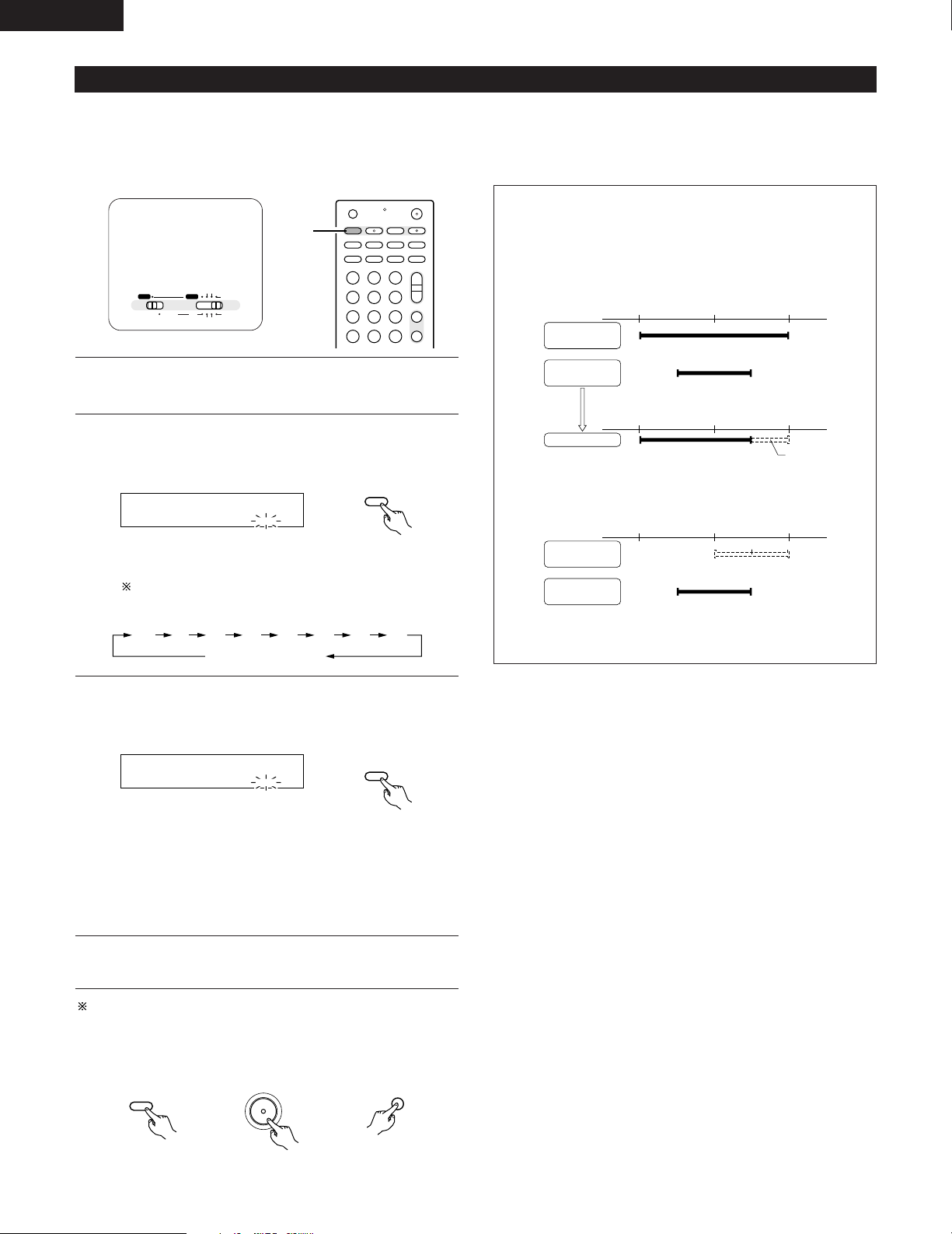
ENGLISH
SLEEP
SOURCE
120
SLEEP
90120 60 50 3040 20 10
SLEEP
SOURCE
50
SLEEP
8:00p.m. 9:00p.m. 10:00p.m.
8:00p.m. 9:00p.m. 10:00p.m.
ON OFF
ON OFF
+
ON OFF
8:00p.m. 9:00p.m. 10:00p.m.
ON OFF
ON OFF
+
ON / STANDBY
OFF
SLEEP
SOURCE
+
-
+
-
A-B REPEAT
SEARCH MODE
ONOFF
REPEAT RANDOM
CLEAR ZOOMSLIDE MODE
PROG/DIRECT
MEMO BANDMODE
TUNER
CH
3
-
+
21
654
987
0
/
10
CALL
+
10
VCR
NTSC/PAL
SLEEP
ENTER
CD SRS
EDIT/MENUCHARAC.
REC
TIMETITLE
TUNING /
TV VOL
TV CH TV CH
TUNERDVD
MD/LINE-1
TAPE/LINE-2
AUTO DECODE
VIRTUALDIRECT
5CH STEREO
STEREO
D.AUX
T VT V INSOURCE
2,3
A / V
SYSTEM MD
CDR TAPE
TUNER TV / VCR
IN/SURR.
IN/SURR.
DVD
(6) Setting the sleep timer (remote control unit only)
• The included remote control unit can be used to turn the power to the standby mode after a maximum of 120 minutes. (Sleep timer)
• Use this function to automatically switch the power to the standby mode after a specific amount of time (minutes).
Example: To set the power to the standby mode in 50 minutesaccording to the clock. Be sure to correct the current time setting.
Set the remote
control selector
switches to A/V
and IN/SURR..
Select and play the desired function.
1
Press the SLEEP button.
2
•“120” is displayed and the “SLEEP” indicator flashes.
The display switches as follows each time the SLEEP
button is pressed:
“SLEEP” indicator off
Remote control unit
NOTES:
• If the SLEEP button is pressed while the sleep timer is
operating, the setting returns to 120 minutes. Make the setting
over.
• If the sleep timer and everyday timer settings overlap, the sleep
timer has priority.
Everyday timer
once timer setting
Sleep timer
setting
If the timers overlap like this, the timer operates as follows:
Timer operation
Does not operate
• Also, the everyday timer will not operate if its start time is set
within the time during which the sleep timer is operating.
Everyday timer
once timer setting
Sleep timer
setting
Does not operate
• The remaining time of the sleep timer can be checked with the
STATUS button.
When the “SLEEP” indicator is flashing, press the SLEEP
3
button again until “50” is displayed.
•“50” is displayed and the “SLEEP” indicator flashes.
• After 4 seconds, the display returns to as it was before the
sleep timer was set, and the “SLEEP” indicator stops
flashing, remaining lit. (This completes the sleep timer
setting.)
The power is set to the standby mode 50 minutes later.
4
To turn the sleep timer off, press the SLEEP button repeatedly until
the “SLEEP” indicator turns off. The sleep timer can also be
turned off by press the power button on the main unit or the
remote control unit to turn the entire system’s power to the
standby mode.
90
Remote control unit
Remote control unit
Main unit Remote control unit
Page 91
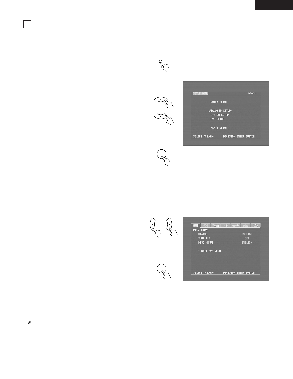
19
ENTER
ENTER
SETUP
CHANGING THE DEFAULT SETTINGS (DVD)
2 The initial setting that was set prior to shipping from the factory can be changed.
The setting contents are maintained until they are next changed even when the power is switched off.
In the stop mode, press the SETUP button.
1
At the Setup Menu, use the • and ª cursor buttons to select
“DVD SETUP” and press the ENTER button.
Remote control unit
d
Remote control unit
d
ENGLISH
The setup (default settings) screen “DVD SETUP MENU”
2
appears.
• DISC SETUP
Use this to set the language to be used when playing the
disc.
If the set language is not offered on that disc, the discs
default language is set.
• OSD SETUP
Use this to set the wall paper color.
• VIDEO SETUP
Use this to set this unit screen mode.
(TV aspect and TV type.)
• AUDIO SETUP
Use this to set this unit audio output mode.
(Digital and LPCM output settings.)
• RATINGS
Use this to disable playback of adult DVDs so that children
cannot watch them. Note that playback of adult DVDs
cannot be disabled if the rating level is not recorded on the
DVD, but that it is possible to disable playback of all DVDs.
• OTHER SETUP
Closed captions (subtitles) and the time interval for playing
still pictures can be set.
Use the 0and 1cursor buttons to select the desired setting
item, then press the ENTER button.
Remote control unit
Remote control unit
d
Remote control unit
To exit the DVD setup mode
Use the 0and 1cursor buttons to select “EXIT SETUP”, then press the ENTER button. It is also possible to quit by pressing the SETUP
button on the remote control unit.
91
Page 92
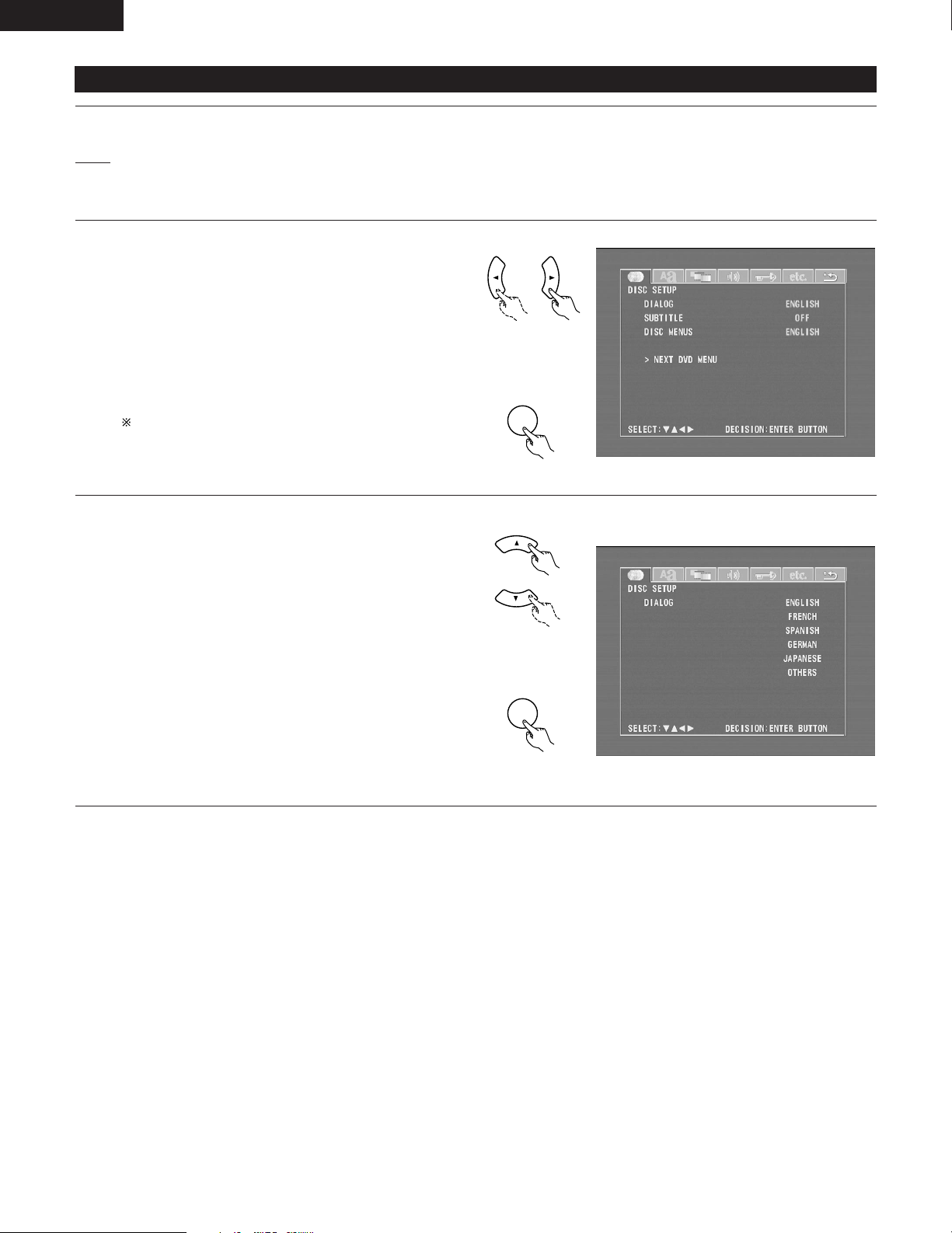
ENGLISH
ENTER
ENTER
(1) “DISC SETUP” is selected
1
2
3
See page 91.
Use the 0and 1cursor buttons to select the “DISC
SETUP”, then press the ENTER button.
• DIALOG
Use this to set the language of the sound output from
the speakers.
• SUBTITLE
Use this to set the language of the subtitles displayed on
the TV.
• DISC MENUS
Use this to set the language of the menus recorded on
the disc (top menu, etc.).
To exit the disc setup mode
Use the •and ªcursor buttons to select “> NEXT DVD
MENU”, then press the ENTER button.
Remote control unit
d
Remote control unit
Use the •and ªcursor buttons to select the desired
setting, then press the ENTER button.
4
When “DIALOG” is selected:
2
• ENGLISH (Factory default)
Select this when you want to play the DVD with the
sound in English.
• FRENCH
Select this when you want to play the DVD with the
sound in French.
• SPANISH
Select this when you want to play the DVD with the
sound in Spanish.
• GERMAN
Select this when you want to play the DVD with the
sound in German.
• JAPANESE
Select this when you want to play the DVD with the
sound in Japanese.
• OTHERS
The sound is played in the language input with the number
buttons. (See the table of language numbers on page 94.)
Remote control unit
d
Remote control unit
92
Page 93
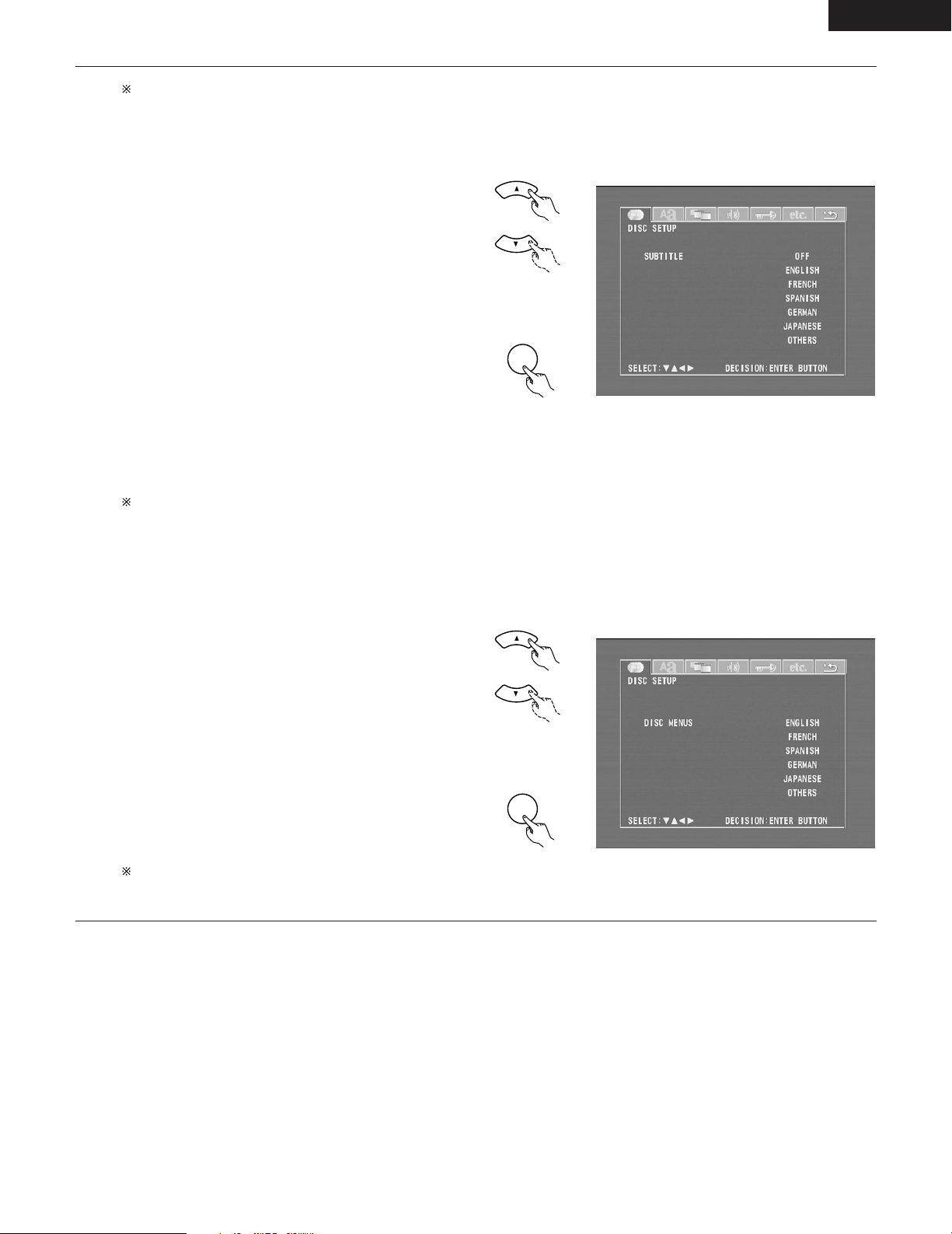
ENGLISH
ENTER
ENTER
4
To exit the dialog mode
Press the ENTER button, you can go back to the previous
screen.
When “SUBTITLE” is selected:
2
• OFF (Factory default)
Select this if you do not want to display the subtitles. (For
some discs it is not possible to turn off the subtitle
display.)
• ENGLISH
Select this when you want to play the DVD with the
subtitles in English.
• FRENCH
Select this when you want to play the DVD with the
subtitles in French.
• SPANISH
Select this when you want to play the DVD with the
subtitles in Spanish.
• GERMAN
Select this when you want to play the DVD with the
subtitles in German.
• JAPANESE
Select this when you want to play the DVD with the
subtitles in Japanese.
• OTHERS
Subtitles are played in the language input with the number
buttons. (See the table of language numbers on page 94.)
To exit the subtitle mode
Press the ENTER button, you can go back to the previous
screen.
Remote control unit
d
Remote control unit
When “DISC MENUS” is selected:
2
• ENGLISH (Factory default)
Select this when you want to display the menus in
English.
• FRENCH
Select this when you want to display the menus in
French.
• SPANISH
Select this when you want to display the menus in
Spanish.
• GERMAN
Select this when you want to display the menus in
German.
• JAPANESE
Select this when you want to display the menus in
Japanese.
• OTHERS
The menu screen is played in the language input with the
number buttons.
(See the table of language numbers on page 94.)
To exit the disc menus mode
Press the ENTER button, you can go back to the previous
screen.
Remote control unit
d
Remote control unit
93
Page 94
ENGLISH
Language code list
Code
6565
6566
6570
6577
6582
6583
6588
6590
6665
6669
6671
6672
6678
6679
6682
6765
Language
Afar
Abkhazian
Afrikaans
Ameharic
Arabic
Assamese
Aymara
Azerbaijani
Bashkir
Byelorussian
Bulgarian
Bihari
Bengali; Bangla
Tibetan
Breton
Catalan
Code
7079
7082
7089
7165
7168
7176
7178
7185
7265
7273
7282
7285
7289
7365
7378
7383
Language
Faroese
French
Frisian
Irish, Scots
Gaelic
Galician
Guarani
Gujarati
Hausa
Hindi
Croatian
Hungarian
Armenian
Interlingua
Indonesian
Icelandic
Code
7678
7679
7684
7686
7771
7773
7775
7776
7778
7779
7782
7783
7784
7789
7865
7869
Language
Lingala
Laothian
Lithuanian
Latvian, Lettish
Malagasy
Maori
Macedonish
Malayalam
Mongolian
Moldavian
Marathi
Malay
Maltese
Burmese
Nauru
Nepali
Code
8375
8376
8377
8378
8379
8381
8382
8385
8386
8387
8465
8469
8471
8472
8473
8475
Language
Slovak
Slovenian
Samoan
Shona
Somali
Albanian
Serbian
Sundanese
Swedish
Swahili
Tamil
Telugu
Tajik
Thai
Tigrinya
Turkmen
6779
6783
6789
6865
6869
6890
6976
6978
6979
6983
6984
6985
7065
7073
7074
Corsican
Czech
Welsh
Danish
German
Bhutani
Greek
English
Esperanto
Spanish
Estonian
Basque
Persian
Finnish
Fiji
7384
7387
7465
7473
7487
7565
7575
7576
7577
7578
7579
7583
7585
7589
7665
Italian
Hebrew
Japanese
Yiddish
Javanese
Georgian
Kazakh
Greenlandic
Cambodian
Kannada
Korean
Kashmiri
Kurdish
Kirghiz
Latin
7876
7879
7982
8065
8076
8083
8084
8185
8277
8279
8285
8365
8368
8372
8373
Dutch
Norwegian
Oriya
Panjabi
Polish
Pashto, Pushto
Portuguese
Quechua
Rhaeto-Romance
Romanian
Russian
Sanskrit
Sindhi
Serbo-Croatian
Singhalese
8476
8479
8482
8484
8487
8575
8582
8590
8673
8679
8779
8872
8979
9072
9085
Tagalog
Tonga
Turkish
Tatar
Twi
Ukrainian
Urdu
Uzbek
Vietnamese
Volapük
Wolof
Xhosa
Yoruba
Chinese
Zulu
94
Page 95
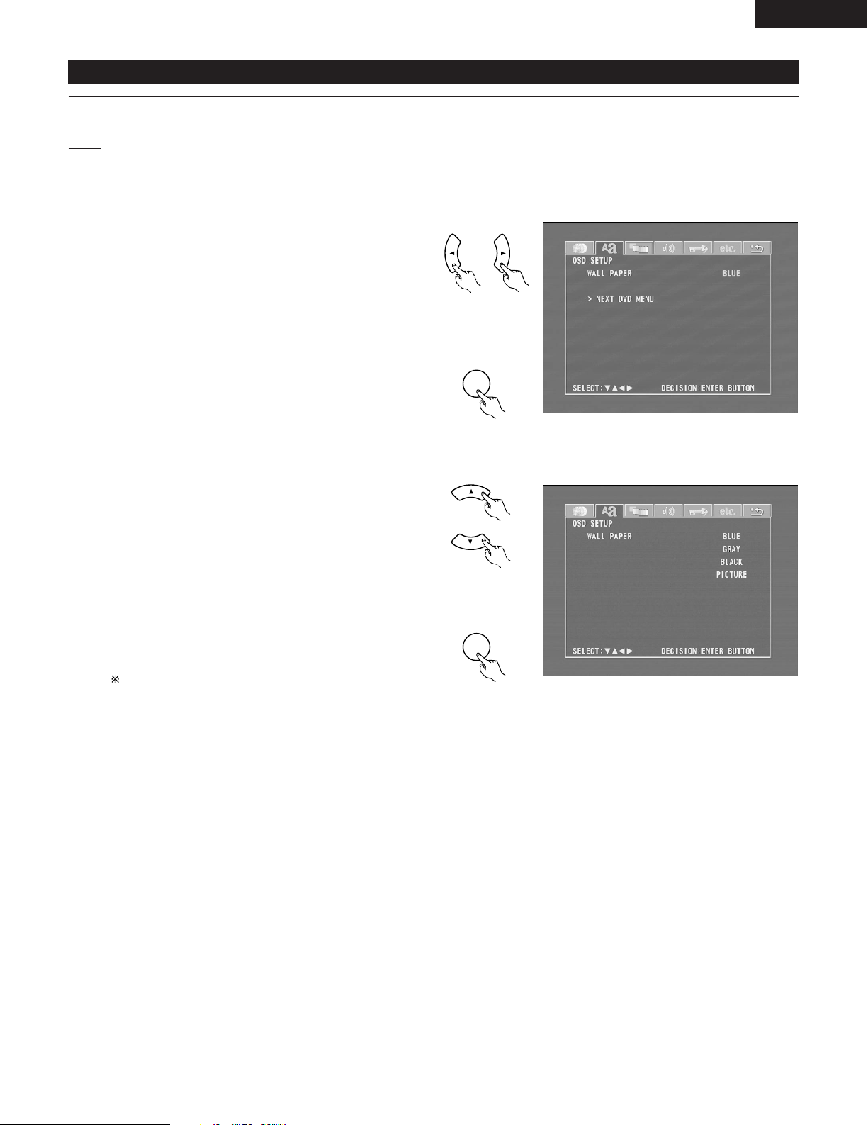
(2) When “OSD SETUP” is selected
ENTER
ENTER
1
If you are not at the DVD setting screen, read steps 1 and 2 on page
91.
2
Use the 0and 1cursor buttons to select the “OSD
3
SETUP” tag icon, then press the ENTER button.
• WALL PAPER
The image displayed when in the stop mode or when
playing a CD can be selected.
ENGLISH
Remote control unit
d
Use the •and ªcursor buttons to select the setting to be
4
set, then press the ENTER button.
When “WALL PAPER” has been selected
2
• Use the •and ªcursor buttons to select the wallpaper.
• BLUE (Factory default)
The wallpaper is set to blue.
• GRAY
The wallpaper is set to gray.
• BLACK
The wallpaper is set to black.
• PICTURE
The wallpaper is set to a picture.
To complete the “WALL PAPER” setting
Press the ENTER button.
Remote control unit
Remote control unit
d
Remote control unit
95
Page 96
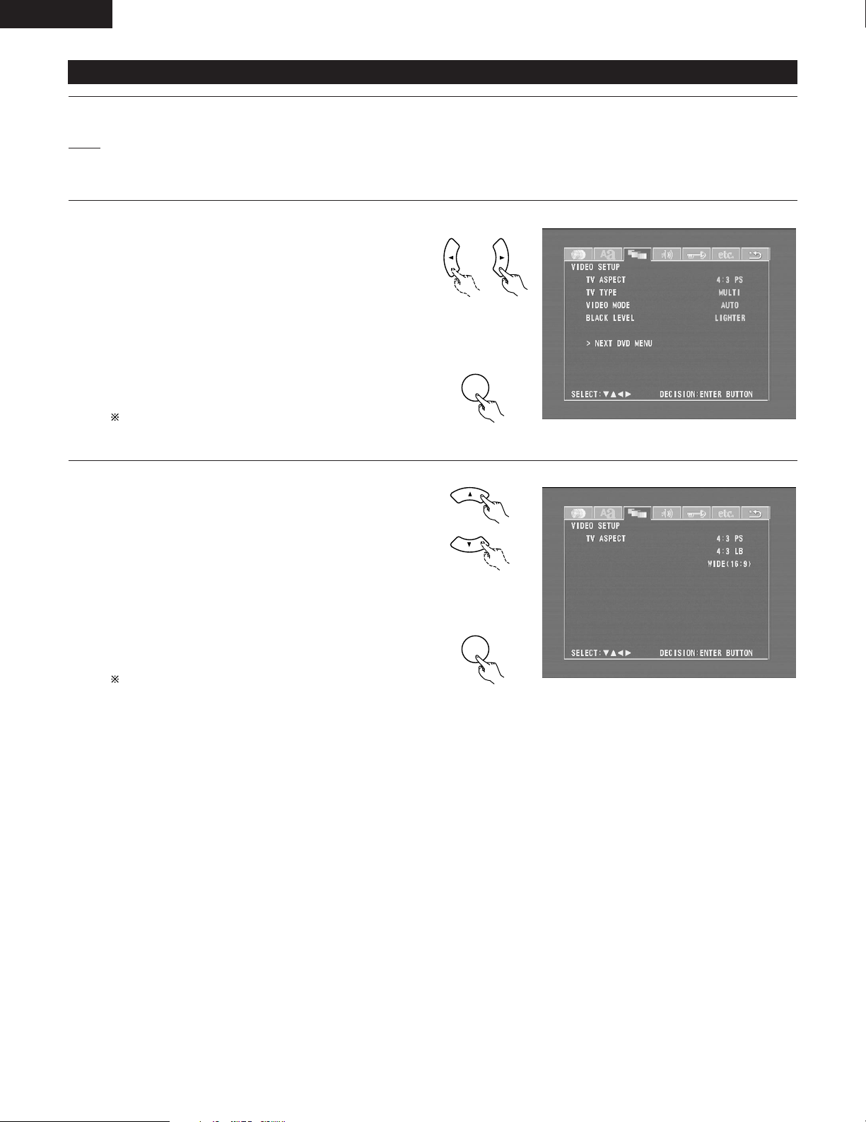
ENGLISH
ENTER
ENTER
(3) “VIDEO SETUP” is selected
1
2
3
See page 91.
Use the 0and 1cursor buttons to select the “VIDEO
SETUP”, then press the ENTER button.
• TV ASPECT
Use this to set the shape of your TV’s screen.
• TV TYPE
Use this to set your TV’s video format (NTSC, PAL or
MULTI).
• VIDEO MODE
Use this to select the video mode. (AUTO, FILM, VIDEO)
• BLACK LEVEL
The picture’s black level can be set to “lighter” or
“darker”.
To exit the video setup mode
Use the •and ªcursor buttons to select “> NEXT DVD
MENU”, then press the ENTER button.
Remote control unit
d
Remote control unit
Use the •and ªcursor buttons to select the desired
4
setting, then press the ENTER button.
When “TV ASPECT” is selected:
2
• 4:3 PS (Factory default)
Select this to play wide DVDs in the pan & scan mode
(with the sides of the picture cut off). Discs for which pan
& scan is not specified are played in the letter box mode.
• 4:3 LB
Select this to play wide DVDs in the letter box mode (with
black strips at the top and bottom).
• WIDE (16:9)
Select this to play wide DVDs in the full-screen mode.
To exit the TV aspect mode
Press the ENTER button, you can go back to the previous
screen.
Remote control unit
d
Remote control unit
96
Page 97
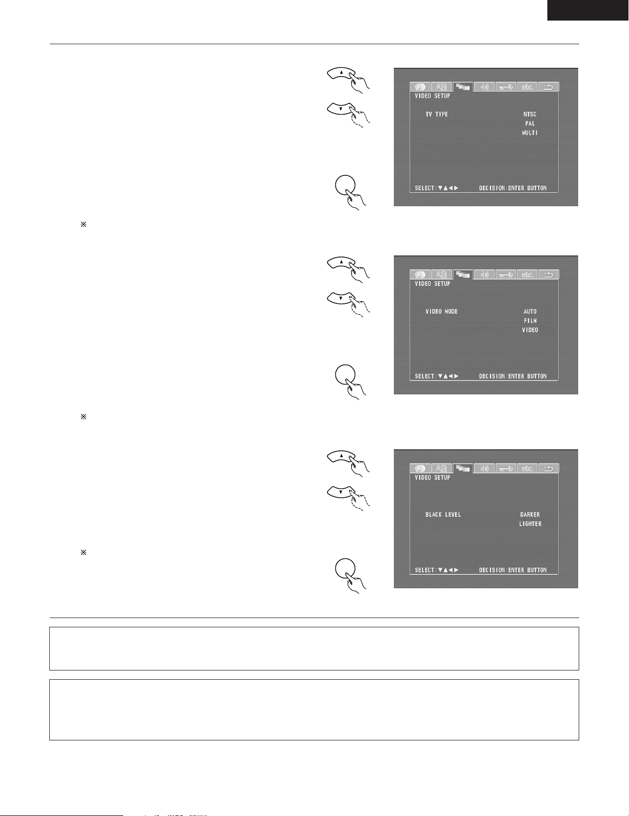
When “TV TYPE” is selected:
ENTER
ENTER
ENTER
2
4
• NTSC (Factory default)
Select this when your TV’s video format is NTSC.
If NTSC is selected, output format is fixed to NTSC.
• PA L
Select this when your TV’s video format is PAL.
If PAL is selected, output format is fixed to PAL.
• MULTI
Select this when your TV is compatible with both the
NTSC and PAL formats.
NTSC signals are output from the video output jacks
when discs recorded in NTSC format are played, and PAL
signals are output from the video output jacks when discs
recorded in PAL format are played.
ENGLISH
Remote control unit
d
To exit the TV type mode
Press the ENTER button, you can go back to the previous
screen.
When “VIDEO MODE” has been selected (see the
2
note below)
• Use the •and ªcursor buttons to select the video mode
to be set.
• AUTO (Factory default)
The mode is selected by identifying the type of material
(film or video flag) from the disc.
• FILM
This setting is suited for playing film material discs or
video material discs recorded with progressive scanning.
• VIDEO
This setting is suited for playing video material discs.
To complete the “VIDEO MODE” setting
Press the ENTER button.
When “BLACK LEVEL” has been selected
2
• Use the •and ªcursor buttons to select the black level.
• DARKER
This sets the black level of the output signals to the
standard level.
• LIGHTER (Factory default)
This raises the standard level for the black level. Set this
if the picture displayed on the TV is extremely dark.
To complete the “BLACK LEVEL” setting
Press the ENTER button.
Remote control unit
Remote control unit
d
Remote control unit
Remote control unit
d
Remote control unit
NOTE:
• For the component output only, it is possible to switch between interlace image output and progressive image output. It is not possible to
specify progressive image output for the Video output connectors or S-Video output connector.
Note on when “VIDEO MODE” is selected
2
• Some discs may not be identified properly (for example discs including both film and video materials). For such discs, try changing the video
mode setting.
• When certain DVD video discs are played, noise in the form of stripes may appear or the picture may be blurred. In such cases, try changing
the video mode setting.
97
Page 98
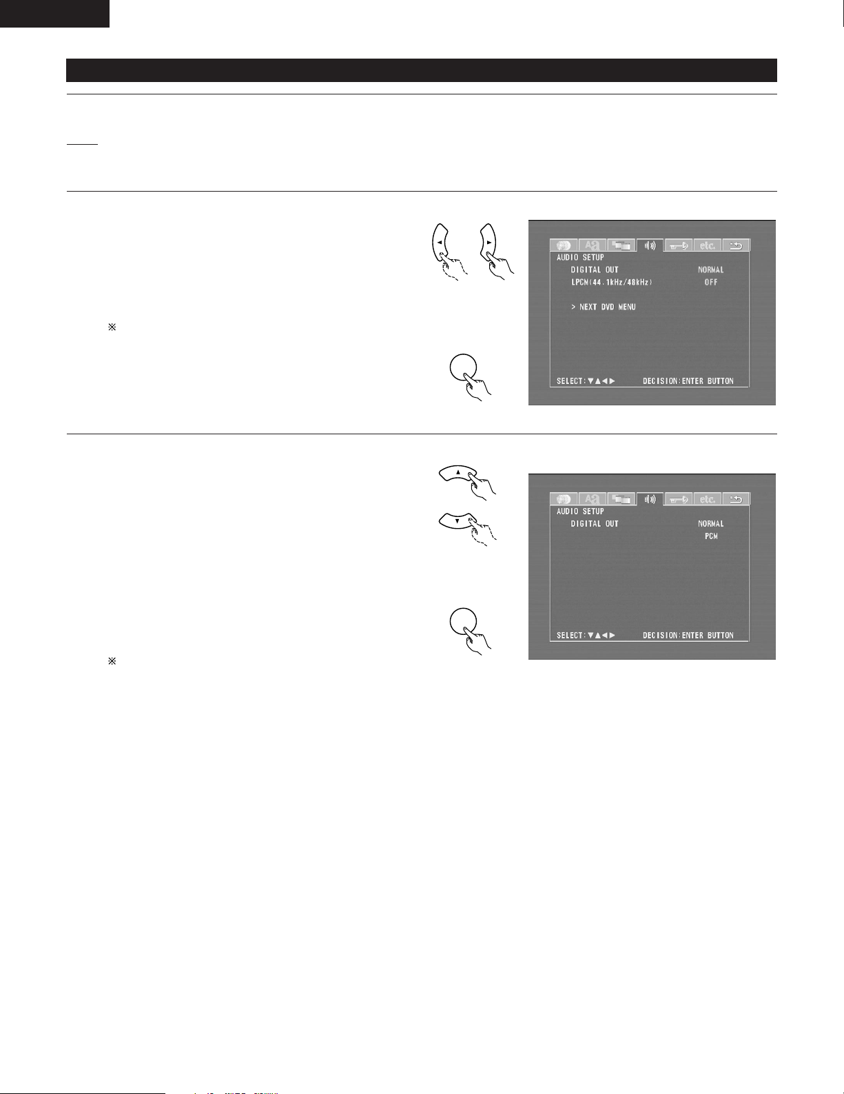
ENGLISH
ENTER
ENTER
(4) “AUDIO SETUP” is selected
1
2
3
See page 91.
Use the 0and 1cursor buttons to select the “AUDIO
SETUP”, then press the ENTER button.
• DIGITAL OUT
Use this to select the digital output’s signal format.
• LPCM (44.1 kHz / 48 kHz)
Use this to set the digital audio output when playing
DVDs recorded in linear PCM audio.
To exit the audio setup mode
Use the •and ªcursor buttons to select “> NEXT DVD
MENU”, then press the ENTER button.
• The screen returns to as it was in step 2.
Remote control unit
d
Remote control unit
Use the •and ªcursor buttons to select the desired
4
setting, then press the ENTER button.
When “DIGITAL OUT” is selected.
2
• NORMAL (Factory default)
Make the selection when playing back in surround
playback a DVD that has been recorded with Dolby Digital
or DTS on this unit.
The Dolby Digital or DTS digital signal is also output from
the digital output jacks.
• PCM
DVDs that were recorded in Dolby Digital DTS are
converted to linear PCM 48 kHz/16 bit (2 channels). Make
the selection when making a digital recording.
To exit the digital out mode
Press the ENTER button, you can go back to the previous
screen.
Remote control unit
d
Remote control unit
98
Page 99
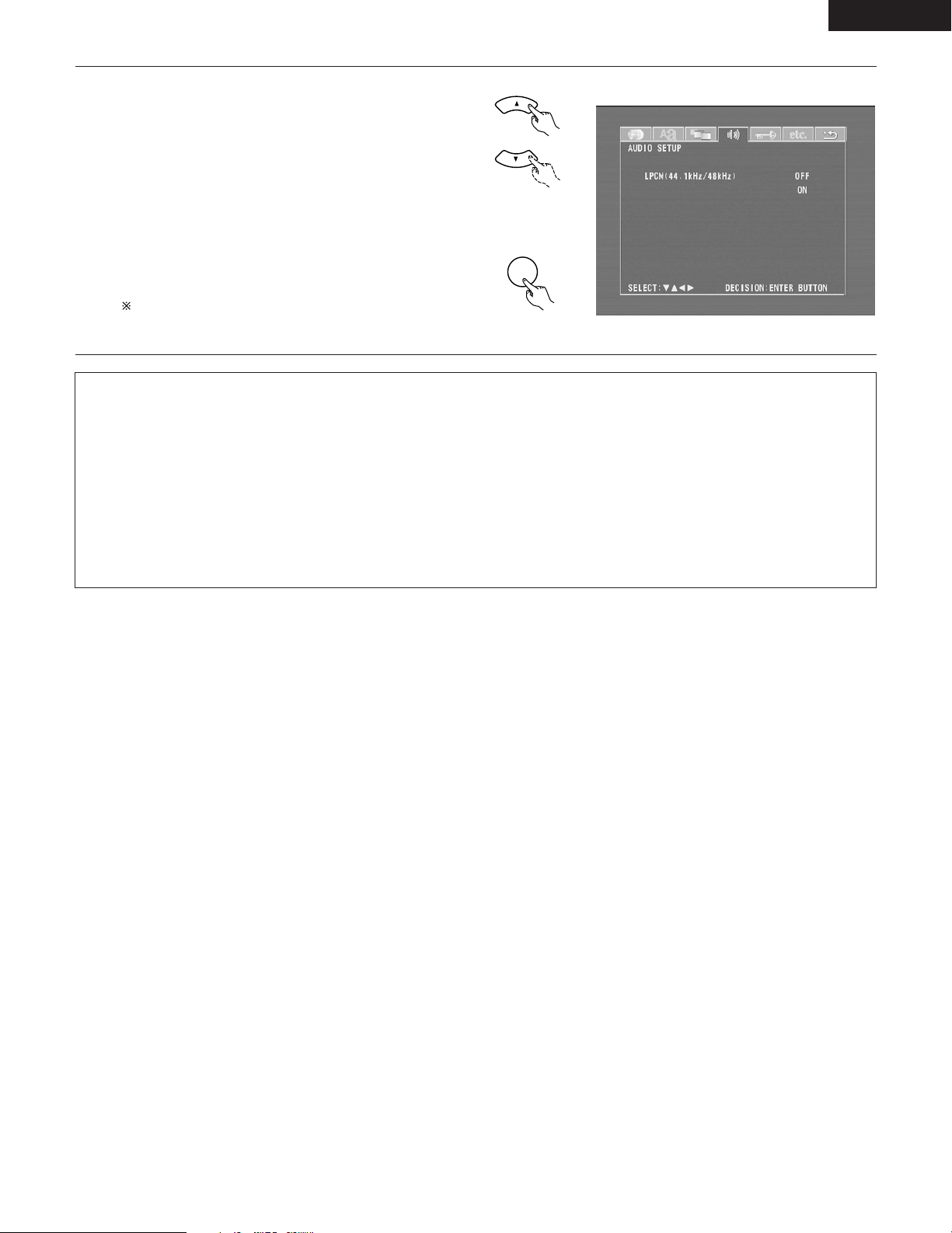
“LPCM SELECT (96 kHz/48 kHz)” is selected.
ENTER
2
4
• OFF (Factory default)
Make the selection when playing back to a decoder DVDs
that were recorded with this unit using linear PCM 48
kHz/20/24 bit and 96 kHz modes. Note that DVDs with
Copyright Protection are converted to 48 kHz/16 bits and
played back.
The same signal is output from the digital output jacks.
• ON
DVDs that were recorded with linear PCM 48 kHz/20/24
bit and 96 kHz modes are all converted to 48 kHz/16 bits.
Make this selection at the time of digital recording.
To exit the LPCM select mode
Press the ENTER button, you can go back to the previous
screen.
NOTES:
• When playing Dolby Digital/DTS surround DVDs or 96 kHz linear PCM DVDs on the ADV-M71, be sure to set “Digital Output” to “Normal”
and “LPCM Conversion Mode” to “Do Not Convert”.
• When and only when you want to output the signals of the Dolby Digital/DTS surround DVD being played on the ADV-M71 to a digital
PCM device, set “Digital Output” to “PCM Conversion”.
With this setting, DVDs cannot be played on the ADV-M71 in the Dolby Digital/DTS surround mode. (The surround mode is set to the
mode in which PCM 2-channel signals can be played.)
• When and only when you want to make a digital recording of the signals of a 48 kHz/20-bit/24-bit or 96 kHz linear PCM DVD being played
on the ADV-M71 onto a digital recorder, set the “LPCM Conversion” to “Convert”.
With this setting it is not possible to decode and play 48 kHz/20-bit/24-bit or 96 kHz linear PCM signals on the ADV-M71 during recording.
(Decoding and playback is in 48 kHz/16-bit linear PCM format.)
Remote control unit
d
Remote control unit
ENGLISH
99
Page 100
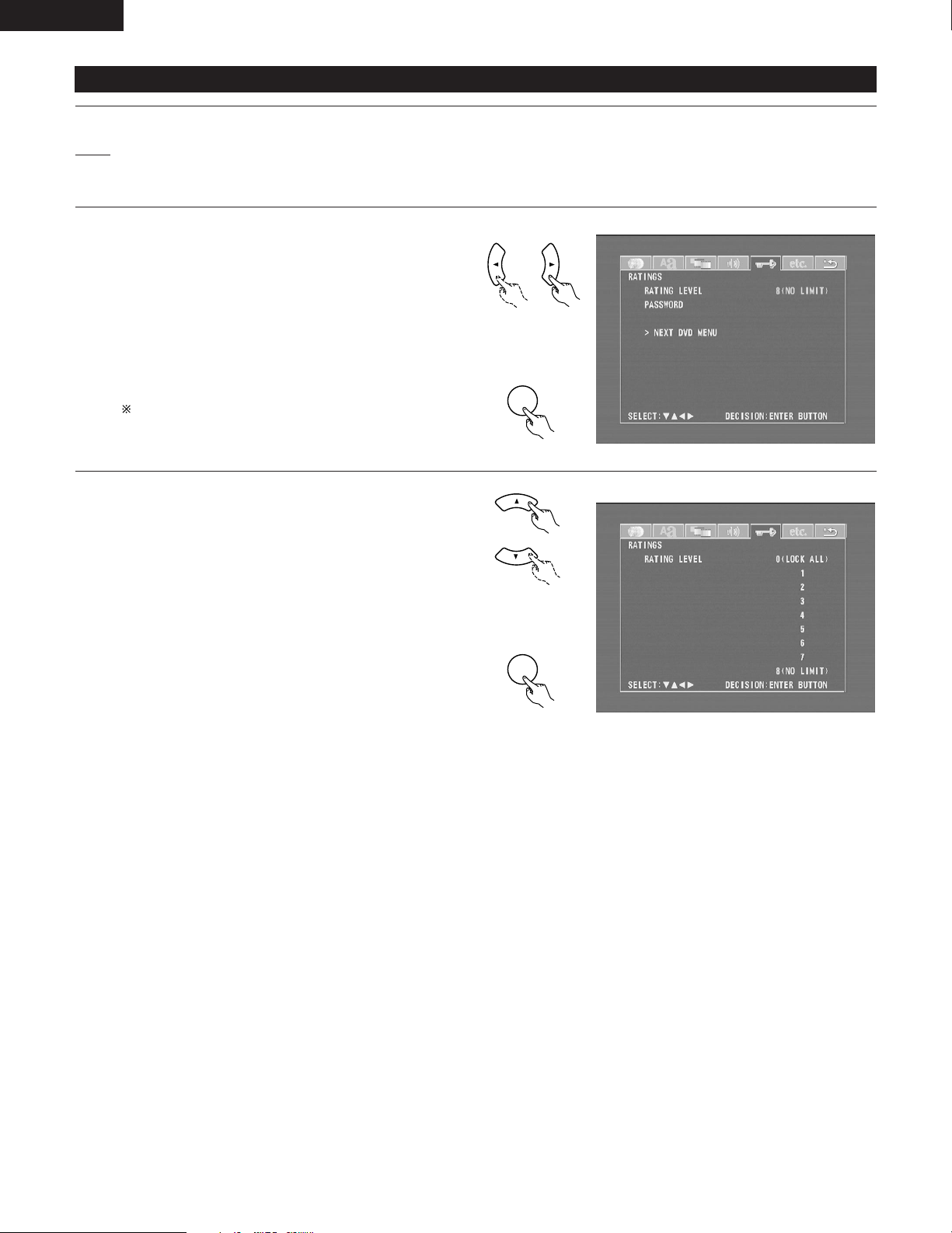
ENGLISH
ENTER
ENTER
(5) “RATINGS” is selected
1
2
3
See page 91.
Use the 0and 1cursor buttons to select the “RATINGS”,
then press the ENTER button.
• RATING LEVEL
Use this to restrict playback of adult DVDs you do not
want children to view. Note that even with adult DVDs,
viewing cannot be restricted unless the restriction level is
recorded on the disc.
It is however possible to disable playback of all DVDs.
• PASSWORD
Use this to change the password.
The set’s password is set to “0000” by default.
To exit the rating setup mode
Use the •and ªcursor buttons to select “> NEXT DVD
MENU”, then press the ENTER button.
Remote control unit
d
Remote control unit
Use the •and ªcursor buttons to select the desired
4
setting, then press the ENTER button.
When “RATING LEVEL” is selected.
2
• Level 0 (LOCK ALL)
Select this to disable playback of all DVDs.
Use this for example to disable playback of adult DVDs on
which the rating level is not recorded.
• Level 1
Select this to play only DVDs for children. (Adult and
general audience DVDs cannot be played.)
• Level 2 to Level 7
Select this to play DVDs for general audiences and
children. Adult DVDs cannot be played.
• NO LIMIT (Factory default)
Select this to play all DVDs.
Remote control unit
d
Remote control unit
100
 Loading...