

Page 1

VER DY20130812RPIF-EN
SECTION 1: GENERAL INTRODUCTION
VER DY20130812RPIF-EN
Table of Contents
SECTION 1: GENERAL INTRODUCTION
SECTION 2: MAIN TECHNICAL INDEX
SECTION 3: COMPONENTS
SECTION 4: LCD SCREEN DISPLAY
SECTION 5: OPERATION
SECTION 6: SAFETY PRECAUTIONS
SECTION 7: TOUBLESHOOTING GUIDE
SECTION 8: MANTENANCE & SERVICE
I. CONTACT INFORMATION
Apex Locator iFinder is manufactured by:
DENJOY DENTAL CO., LTD
Address: 4
No. 229 Tongzipo Road West, Changsha City, P. R. China 410205
Website: www.denjoy.cn
E-mail: [email protected]
Manufacturing:
Company name: DENJOY DENTAL CO., LTD
Address: 4
No. 229 Tongzipo Road West, Changsha City, P. R. China 410205
Authorized European Representative:
Company name: SPETECHCULAR
Address: 16, Quainton Close, Cambridge, CB5 8LR. UK
th
Floor, A3 Building, Lugu International Industry Park,
th
Floor, A3 Building, Lugu International Industry Park,
LTD
SECTION 9: CLEANING AND DISINFECTION
SECTION 10: STORAGE AND SHIPPING CONDITIONS
SECTION 11: PACKING LIST
1
Please contact local sales distributor from whom you purchase this
unit for user’s record and further after-sale service.
2
Page 2
VER DY20130812RPIF-EN
II. PRODUCT DESCRIPTION
Apex locator iFinder is our latest model with touch-screen LCD used
for determining the position of apex of root canal with the up-to-date
technology multi-frequency operation system.
Distinctive Features:
VER DY20130812RPIF-EN
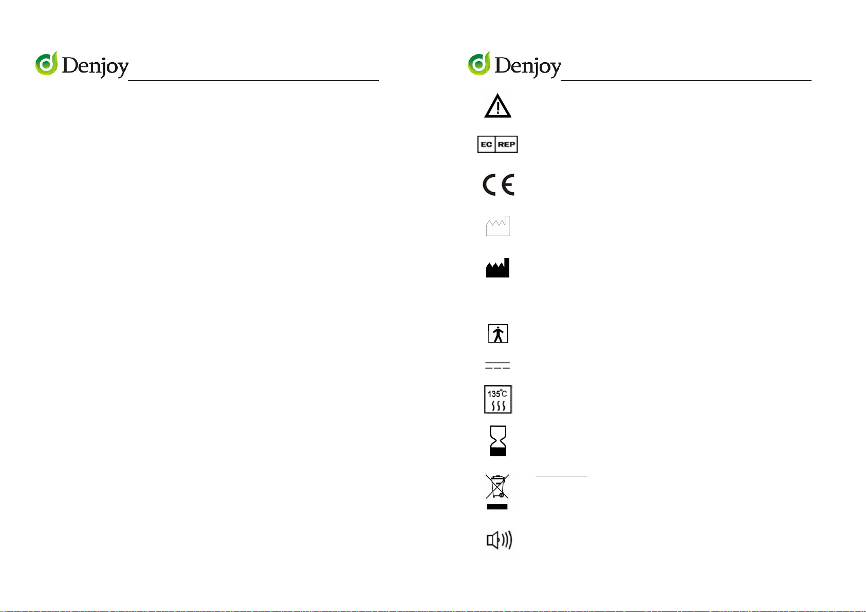
Caution: Consult accompanying documents
Authorized Representative in the European
Community
CE Mark: conforms to essential requirements of the
Medical Device Directive 93/42/EEC.
● High-precision Touch-Screen LCD
● Image save function with Micro-SD memory card (TF card 2G)
● It is equip with separate calibrator test instrument which can check
the operation of control part and spare parts of apex locator when
apex locator doesn't measure well.
● Touch-screen key and traditional button control both available
Other Features:
● 4.3 inch large color screen with real-time graphic of root canals
● Foldable design to create more choices for view angle
● Up-to-date multi-frequency operating system
● Rechargeable, do not need prepare extra battery.
III. SYMBOL DESCRIPTIONS
The following symbols may appear in this manual, on the label, or on
it’s accessories. Some of the symbols represent standards and
SN
Date of manufacture.
Manufacturer
Specifies serial number
Type BF applied part
Direct current
Sterilizable up to the temperature specified at most
The device should not be used after the end of the
shown or the day
DISPOSAL:
municipal waste. Collection of such waste
separately for special treatment is necessary.
Do not dispose this product as unsorted
compliances associated with the Apex Locator and its use.
3
alert indicator displayed on the LCD screen
4
Page 3
VER DY20130812RPIF-EN
SECTION 2: MAIN TECHNICAL INDEX
1. Maximum valid values of amplitude
Valid values of amplitude between file holder and stainless
electrode hook is ≤130mV
2. AC Adapter:Input voltage:100-240V 50/60Hz 0.25A
Output voltage:5V 1A
Battery:3.7V 2200mAh
3. Display mode: 4.3 inch TFT 480*272 color screen
4. Dimensions: 132*120*31mm
5. Weight: about 500g
6. Classification: Internally powered equipment,
VER DY20130812RPIF-EN
7. Degree of protection against electric shock
---Type BF applied part
8. Operation mode: Continuous
SECTION 3: COMPONENTS
5
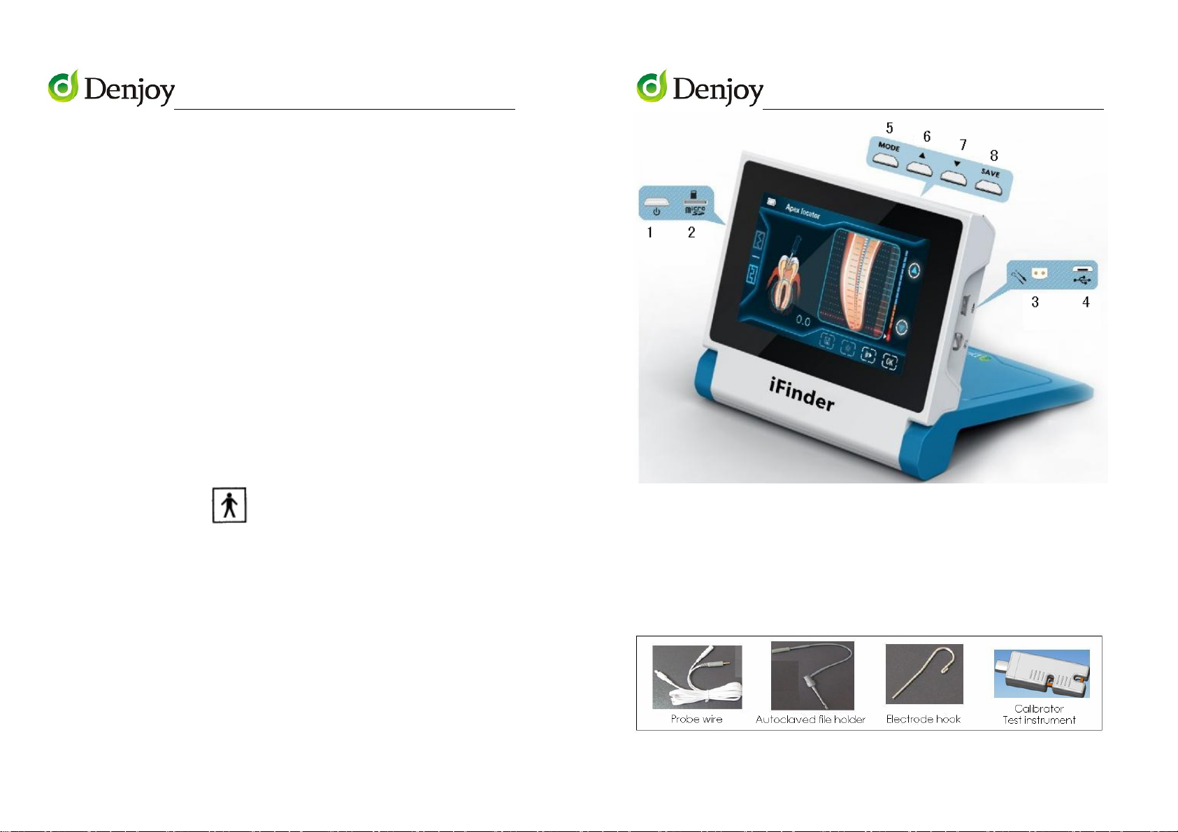
1. Power on/off 2. TF card socket
3. Probe wire socket 4. AC adapter socket
5. Mode key 6. Up key
7. Down key 8. Save key
Main Accessories:
6
Page 4
VER DY20130812RPIF-EN
SECTION 4: LCD SCREEN DISPLAY
VER DY20130812RPIF-EN
On the Main Interface, after insert the TF card, touch save key, as
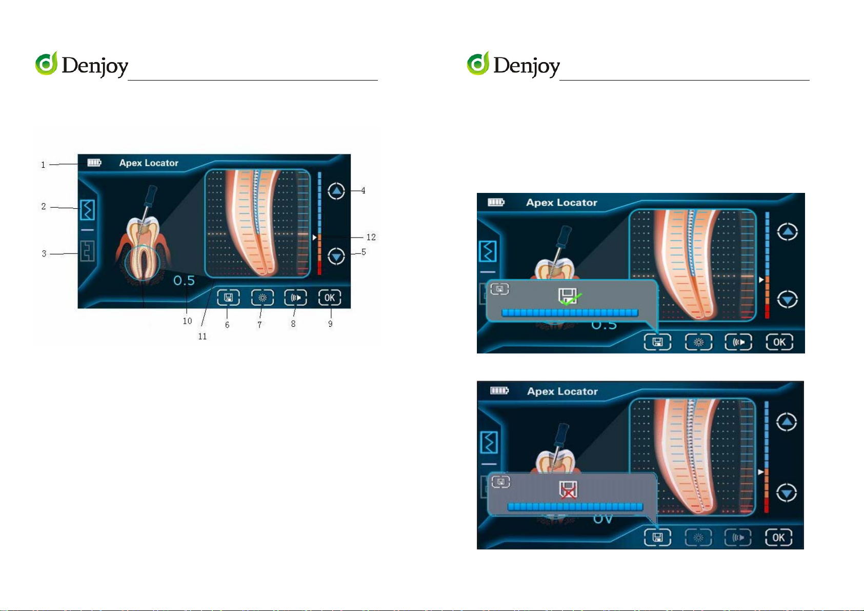
I. APEX LOCATOR INTERFACE
1. Battery sign 2. Main interface
3. Self-calibration interface
4. Up key for length adjuster of apical constriction
shown in Figure 1, it means save successfully. Otherwise, If no TF card
inserted or something wrong with TF card, as shown in Figure 2, it
means save unsuccessfully. Please note: no operation for 3 seconds, it
will automatically return to Main Interface.
Figure 1
Figure 2
5. Down key for length adjuster of apical constriction
6. Save key 7. Brightness control key
8. Sound adjuster 9. Enter (Confirmation OK) key
10. Length between top of file and the apex of root canal
11. Scale displaying the magnified apex area
12. Apical Area Adjustment cursor
a, Save key
7
8
Page 5
VER DY20130812RPIF-EN
b, Brightness control key
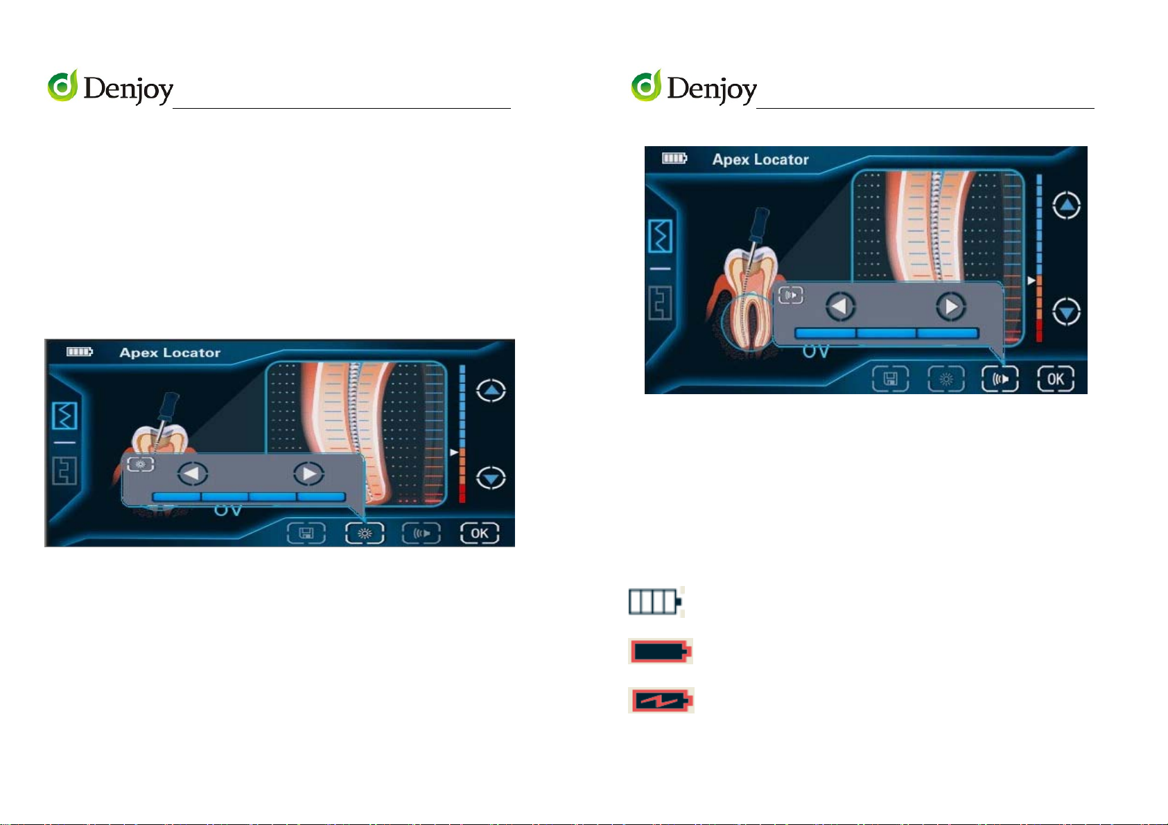
On the Main Interface, user can adjust the 4 level brightness of the
screen by touching the brightness control ket. After adjustment, touch
the enter key, as shown in Figure 3, it means set successfully. Please
note, no operation for 10 seconds, it will automatically return to Main
Interface..
Figure 3
VER DY20130812RPIF-EN
Figure 4
d, Up/Down key for length adjuster of apical constriction
On the Main Interface, user can touch up/down key for length
adjuster of apical constriction to adjust the apical area.
c, Sound adjuster
On the Main Interface, touch sound adjuster, user can select
required volume level, after adjustment, touch enter key, if as shown in
Figure 4, it means set up successfully.
Please note, no operation for 10 seconds, it will automatically return
to Main Interface.
9
e, Battery sign
The symbol lies on the top left corner of the screen.
Full charge
When it is flashed, please charge immediately.
Battery is charging.
10
Page 6
VER DY20130812RPIF-EN
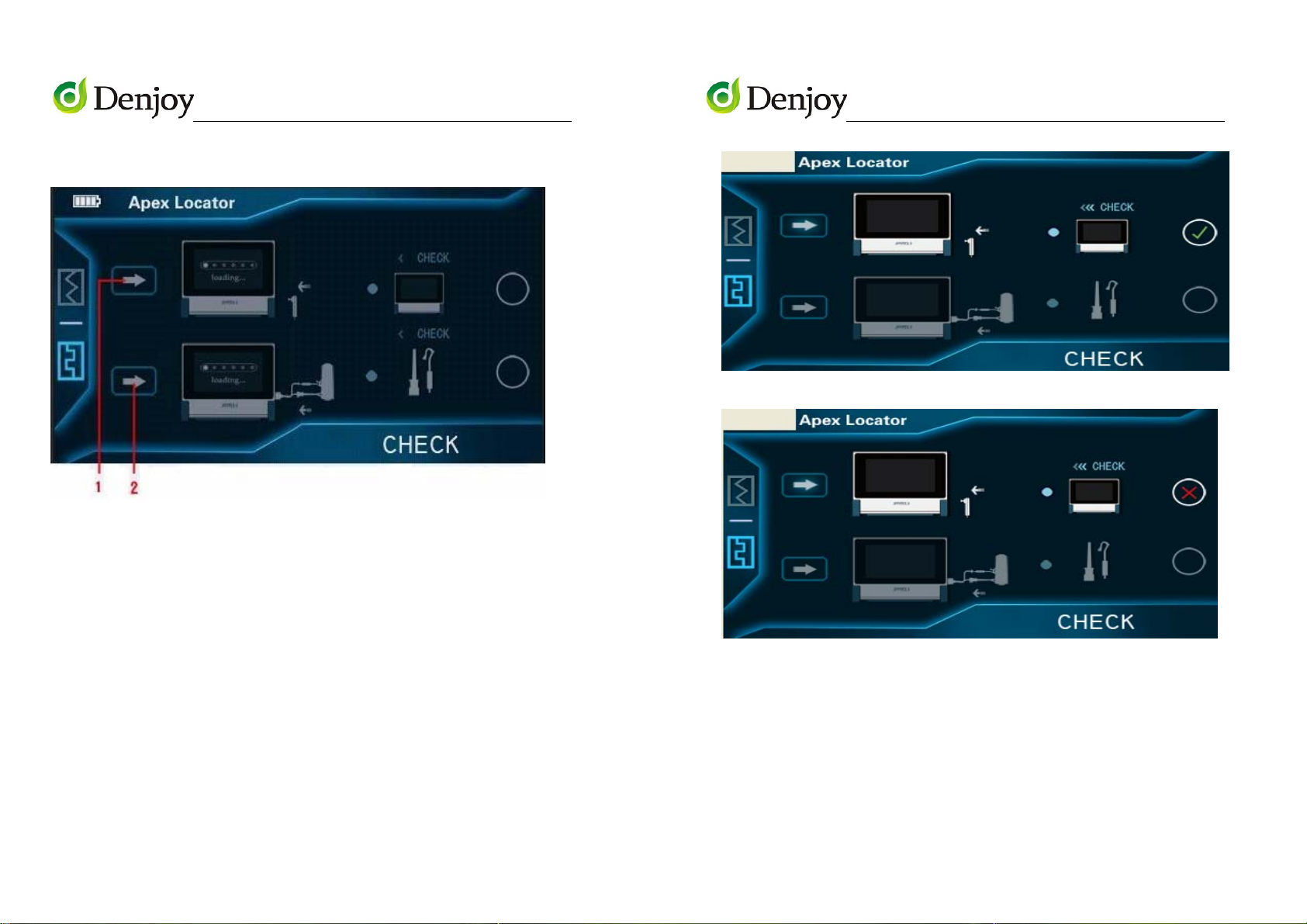
II. SELF CALIBRATION INTERFACE
MARK 1. Calibration key for control part
MARK 2. Calibration key for accessories (probe wire, file holder and
VER DY20130812RPIF-EN
Figure 5
Figure 6
hooks)
a, Calibration key for control part
On the self-calibration interface, insert the calibrator test instrument
into matching socket, touch calibration key for control part (MARK 1),
if as shown in Figure 5, it means self-checking successfully. Otherwise, if
as shown in Figure 6, it means self-checking unsuccessfully.
11
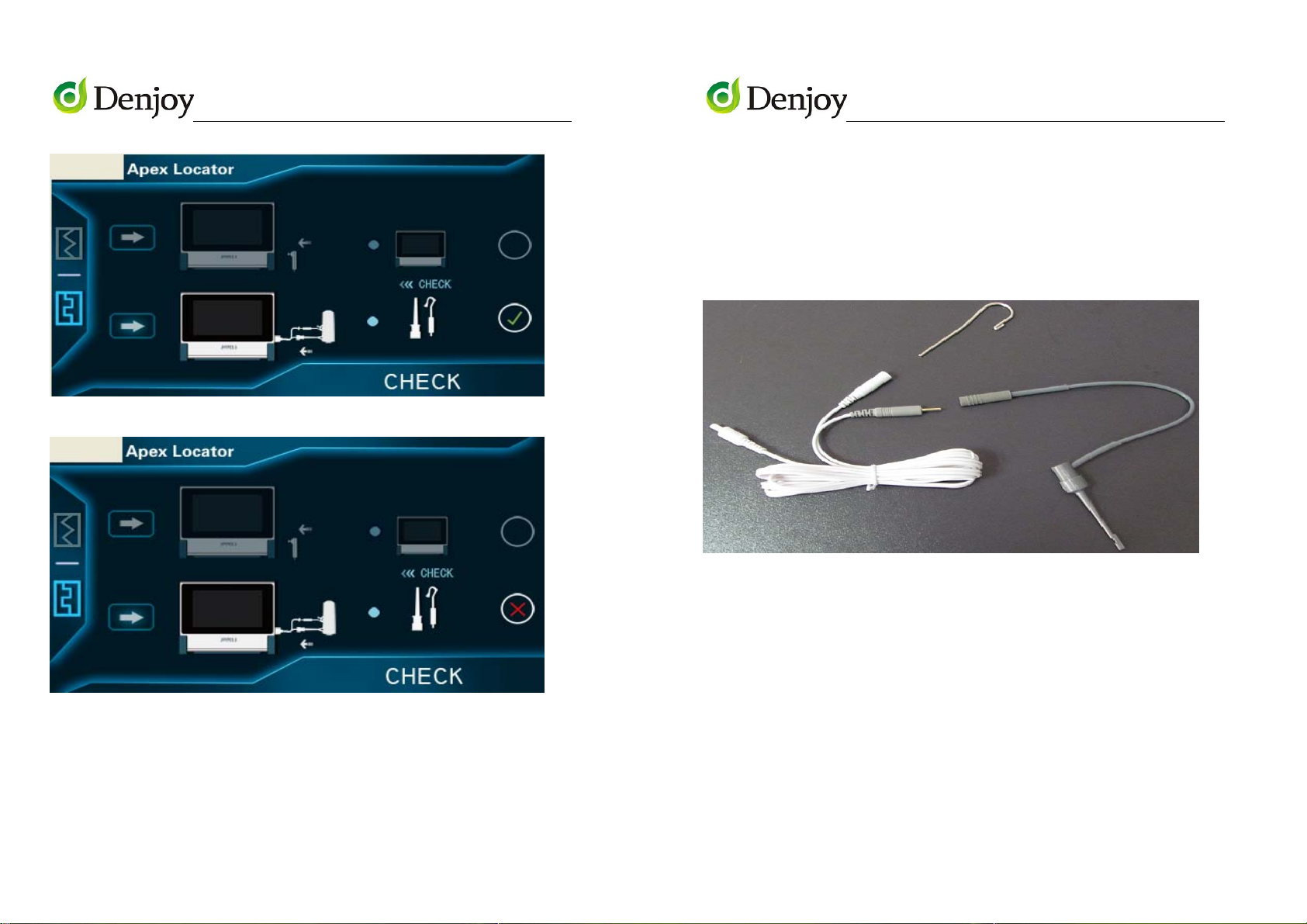
b. Calibration key for accessories (probe wire, file holder and hooks)
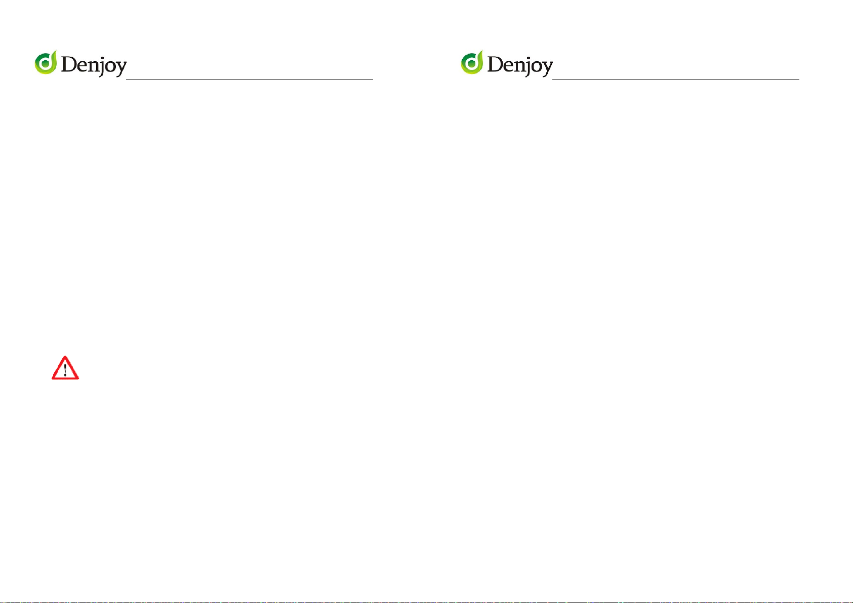
On the self-calibration interface, insert the probe wire into matching
socket, connect calibrator test instrument with file holder and
electrode hook, touch Calibration key for accessories (MARK 2), if as
shown in Figure 7, it means self-checking successfully. Otherwise, if as
shown in Figure 8, it means self-checking unsuccessfully.
12
Page 7
VER DY20130812RPIF-EN
Figure 7
Figure 8
VER DY20130812RPIF-EN
1. The plug of the probe wire should be completely inserted into the
socket on the right side of the control part.
Note: Do not pull out the probe wire by taking the wire instead of
catching hold of the plug to avoid breaking down the probe wire.
2. Please connect file holder to probe wire and insert the stainless
electrode hook into the socket.
SECTION 5: OPERATION
Touch-screen key and traditional button control are both available!
13
3. Extended pressing power on/off button,
Note: Extended pressing power on/off button for 2 seconds to turn
on/off the device.
4. Clip the metal part of the endodontic file with the holder, then insert
the file into the teeth.
5. Hang the stainless hook up at any side of the suffer’s mouth, insert
the file into the teeth, when the endodontic file reaches the position
which the number indicated in the color screen is 0.5mm. Then please
fasten the file with the rubber positioning ring on the reference point of
the tooth crest. And this means that the file has reached the position
14
Page 8
VER DY20130812RPIF-EN
of the apical constriction. (Generally we suggest to use 0.5 for
VER DY20130812RPIF-EN
measurement result.
measurement the length of root canal).
Note: Please do not make the measurement when in charge.
6. Deciding the working length of root canal
Measure the distance from the bottom of rubber positioning ring to
the tip of the file until the figure indicated 0.5. So the length of root
canal need to minus 0.5~1.0mm is the most suitable working length of
root canal.
The working length of root canal varies from different shapes of
teeth and root canal.
7. After operation, please pull out the probe wire and switch off the
instrument. If the dentists forgot to switch off the instrument, the
instrument will automatically shut down.
SECTION 6: SAFETY PRECAUTIONS
a. Before operation, you have to read user manual carefully.
CAUTIONS:
When change the battery, do not mix the old battery with the new
one and mix the alkali battery with the manganic one.
Please take off the battery in the event of longtime nonuse or long
–distance transit.
d. Please use the file with the resin handle rather than metal one.
Even when using the file with the resin handle, please notice that the
fingers should be avoided touching the mental part of the file.
e. Please clip the upper portion of the file rather than the down
portion with the holder, other wise, the metal part of the holder and
the resin part of the file would be damaged. The damaged holder will
affect the measure result.
f. When the file accidentally touches the inner part of the
root-canal, the reading of scale will get a bit abnormality, then will get
right automatically a few seconds later.
g. The device is not suitable for use in the presence of flammable
anesthetic mixtures with air or with oxygen or nitrous oxide.
h. The enclosure of the main body of device is not designed to give
b. Like all of the other electric facilities, this machine has an
electromagnetism disturbance. When there is a patient who is now
using the cardiac pacemaker, or there is an electronic operation,
please don't put the machine around. The cardiac pacemaker
sufferer, viz. the serious cardiac pulse abnormality sufferer, is forbidden
to use this machine.
c. Please put in the battery before use. Make sure that the power
of the battery is in sufficient supply to guarantee the correct
15
any protection against ingress of water. Please keep the device away
from any harmful ingress of water.
For ACCURATE MARESUREMENT:
● Make sure that stainless hook entirely contact patient’s mouth
mucosa
● Check all connections
● Make sure that when the device is switched on, the device can
16
Page 9

VER DY20130812RPIF-EN
complete self-checking procedure automatically and successfully.
VER DY20130812RPIF-EN
Question: No alert
When following situations appear, please use paper point part to
make root canal dry to increase accuracy of measurement.
● It will cause bad electrical conduction between root canal and
metal or dental crown if overfull liquid.
Other problems need to check:
● Make sure that endodontic file was getting through the top hole of
the root canal, the loose file will lead to measure incorrectly.
● If the diameter of apical is more than 0.4mm, it will affect the
accuracy
● Complicated root canal environment also will affect the accuracy
● Make sure that the battery is not too low, or it will lead to faulty
measurements
● Avoiding endodontic file and probe contacting metal prosthesis, or
it will form the earth current and lead to inaccurate indicating root tip.
● If the root canal is too dry, please inject the NaOCI into the apical
foramen.
Answer:
a. Check the alert adjustor button of panel on top of unit.
b. The file has not reached the point less than 2mm at which the
machine will give an alert.
Question: NO changes or incorrect reading on the LCD screen
Answer:
a. Do not clip the file with the holder firstly and switch on the machine
secondly.
b. Remember to hang the stainless hook up at any side of the sufferer's
mouth.
c. Check probe wire connections both at unit and at AC outlet to be
sure they are properly seated.
d. The metal part of the file holder may be polluted or corroded
SECTION 8: MANTENANCE & SERVICE
I.MANTENANCE
SECTION 7: TOUBLESHOOTING GUIDE
Question: After switch on the machine, the LCD screen has no
reaction.
Answer:
a. Check that the machine if it need to be changed.
17
Warranty
The device is maintained free of charge and doesn't require any
routine maintenance within warranty period.
This instrument described below has been fully inspected and
confronts to the current products specification.
Do not modify and disassemble the device.
This instrument is guaranteed for its designated use, against original
18
Page 10

VER DY20130812RPIF-EN
defects in materials and workmanship for a period of 12 months from
VER DY20130812RPIF-EN
Please wipe the probe wire with the soft cloth stained with ethanol
date of purchase. Products warranty or service will not be extended if
(1) the product is repaired, modified, misused, disassembled, or using
the parts are not provided by the manufacturer, (2) The serial number
of the product is defaced or missing.
Please contact local sales distributor from whom you purchase this
unit for user’s record and further after-sale service.
1) Please keep the machine under the environment without X-ray or
sunlight. The temperature outside could be -10 ℃~55 ℃ , humidity
range under 90%, Atmospheric pressure: 80 – 106 Kpa.
2) When the machine has stopped use for 6 months, please recharge
the battery for 5 minutes for restart the battery. If the machine does not
get into use for very long time, please recharge battery 5 minutes each
3 months.
3) The machine has the life span for 5 years.
SECTION 9: CLEANING AND DISINFECTION
MAIN BODY CLEANING INSTRUCTION
When the surface of main body is polluted, please rub the surface
with dry soft cloth ONLY.
REMARKS:
Any liquid lotion like ethanol, banana oil and light oil are not allowed.
PROBE WIRE CLEANING INSTRUCTION
and reuse it after it is completely dry.
ELECTRODE HOOK AND FILE HOLDER DISINFECTION
INSTRUCTION
The front part of the file holder, which is easily get polluted with rubbish
and liquid medicine, should be disinfected by the ethanol.
Stainless electrode hook and file holder should be disinfected at
temperature 121℃ for 20 minutes and disinfection by autoclave is
preferred.
SECTION 10: STORAGE AND SHIPPING CONDITIONS
Ambient temperature: -10℃ ~ 50℃
Relative humidity range: ≤80%
Atmospheric pressure: 50KPa~ 106KPa
Equipment is not suitable for storage in the presence of sunlight, rain,
dust, corrosive gasoline and volatile without poor ventilation.
Transportation is applicable to all common methods.
SECTION 11: PACKING LIST
iFinder Control Part 1pc
Probe Wire 1pc File Holder 2pcs
Stainless Hook 4pcs Calibrator Test Instrument 1pc
User’s Manual 1pc
19
20
Page 11

VER DY20130812RPIF-EN
WARRANTY REGISTRATION FORM
Item Name:
Model Name:
Serial No.:
Date of Purchase:
Name:
Address:
Phone:
Email:
Name of Distributor:
Authorized Distributors:
Stamp and Signature
21
 Loading...