

Page 1
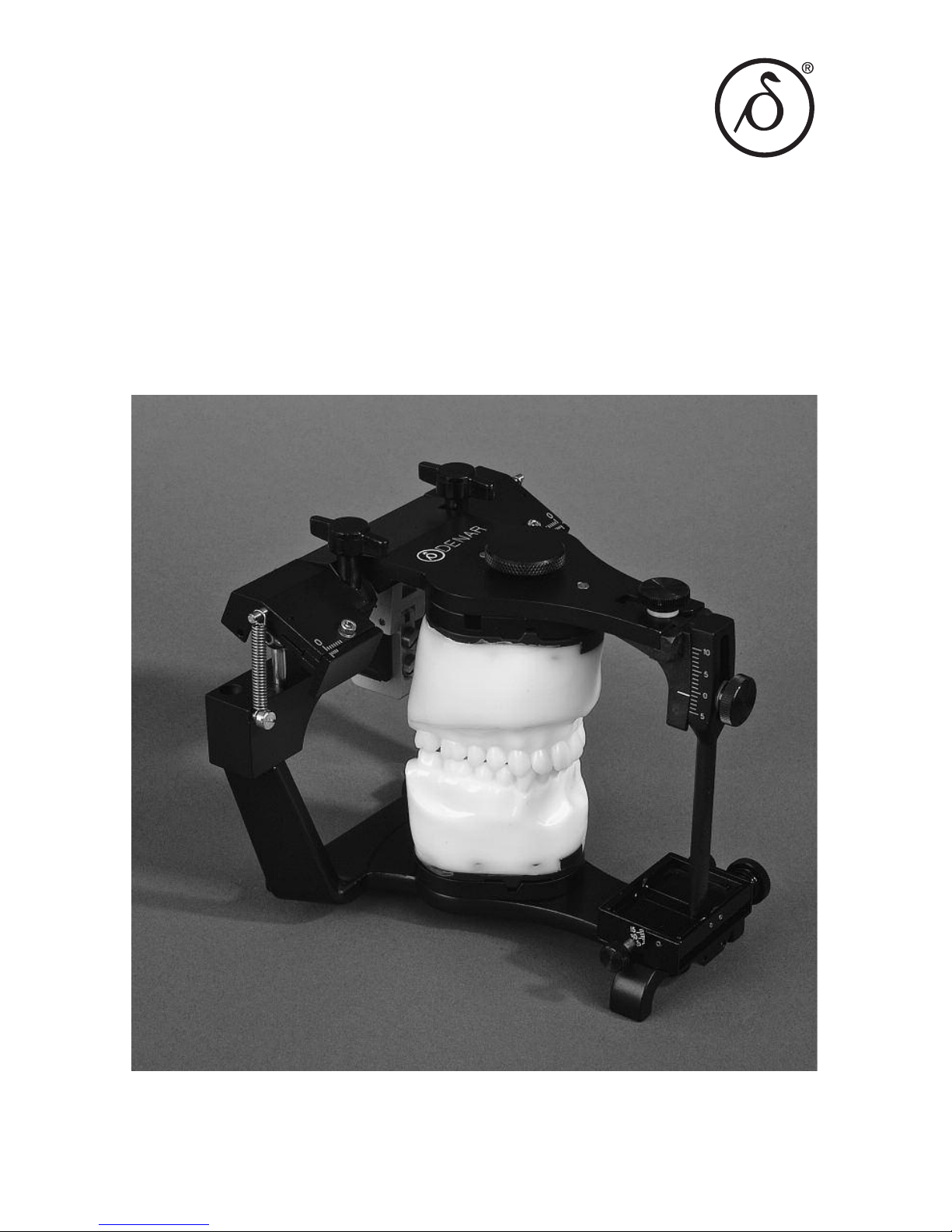
The Dénar
®
Mark II System
TECHNIQUE MANUAL
Page 2

Page 3

The Dénar
®
Mark II System
TECHNIQUE MANUAL
Published by
Whip Mix Corporation - West
1730 East Prospect Rd., Suite 101
Fort Collins, CO 80525
Toll-Free: 1-800-201-7286
Fax: 1-970-472-1793
www.whipmix.com
Page 4

ACKNOWLEDGEMENTS
The Mark II System was developed to fill a need that existed primarily in dental
schools, but also among practicing dentists and laboratory technicians. The Schools
of Dentistry expressed a desire for an effective teaching system that was competitively priced. Practicing dentists and technicians expressed a need for a simple Arcon
articulator that was anatomically accurate which could be used for simple restorative
procedures and to mount diagnostic casts when illustrating occluso-condylar relations to patients for case presentations. There was also a need for an instrument system offering an intermediary step to the incorporation of the principles of occlusion
as well as one offering upward potential to more advanced systems.
We set these needs as our objectives and proceeded to accomplish the task with the
help of many professionals who provided us with both direction and assistance for
which we are most grateful.
Doctors Rex Ingraham, Patrick M. Walker, Donald C. Curntte, Albert Solnit, Howard
M. Landesman, Glen D. Richardson, all at the University of Southern California, gave
us extremely valuable inputs with respect to the needs of the undergraduate students. We are indebted to them particularly for their constructive criticism, even
though painful at the time.
A special word of appreciation is expressed to Doctors Sumiya Hobo and Frank V.
Celenza for their contributions in the early design phases of the instrumentation system.
In planning the preparation of the Mark II Technique Manual, it was our intent that it
encompass more than just mechanical instruction in the use of the Denar
®
Mark II
System. We wanted to offer more by also providing related instruction in the theory
of occlusion as it directly pertains to the use of the instrument. Special credit must go
to Dr. Niles F. Guichet for his contributions and the time he spent working with us,
particularly in view of the demands of his teaching schedule.
We wish to acknowledge the direction and wisdom that we received from Doctors L.
D. Pankey, Loren Miller, Henry Tanner, James Zuccarella, Mel Steinberg, and Mr. Jack
Snyder, of the Pankey Institute, with respect to how the system can be used by practitioners wishing to render quality dentistry through the incorporation of the principles
of occlusion. A great deal of encouragement in this area was also received from Dr.
Peter E. Dawson to whom we are equally grateful.
To insure the System’s compliance with the purest theories of gnathology we are
most indebted to Dr. Peter K. Thomas. He made what seems like “impossible
demands” to arrive at perfection. Fortunately, his toughness was matched with a
great deal of patience.
Through the development phases many different opinions were expressed, but there
was at all times one common goal: to provide dentistry with a quality occlusal instrumentation system. We believe we accomplished this goal. This feat took the efforts,
contributions, dedication and assistance of many more people not mentioned, and to
all of them as well: we are very grateful.
Page 5

CONTENTS
I. Introduction
Who Should Use The Mark II System . . . . . . . . . . . . . . . . . . . . . . . . . . . . . 5
Why Should The Mark II System Be Used . . . . . . . . . . . . . . . . . . . . . . . . . 6
II. The Denar®Mark II Articulator (Semi-adjustable)
Articulator Manipulations. . . . . . . . . . . . . . . . . . . . . . . . . . . . . . . . . . . . . . . 7
Articulator Adjustments . . . . . . . . . . . . . . . . . . . . . . . . . . . . . . . . . . . . . . . . 8
Hand Grasps . . . . . . . . . . . . . . . . . . . . . . . . . . . . . . . . . . . . . . . . . . . . 10-11
III. Relating Condylar Movements to Occlusal Anatomy . . . . . . . . . 12-16
IV. The Immediate and Progressive Side Shift
Adjustments (Bennett Shift) . . . . . . . . . . . . . . . . . . . . . . . . . . . . . . . . . . 17
V. The Denar®Mark II Facebow/Earbow (Model D31AB)
Locating Three Reference Points on Patient’s Face . . . . . . . . . . . . . . . . . 19
Making the Facebow/Earbow Registration . . . . . . . . . . . . . . . . . . . . . . . . 21
Transferring the Facebow/Earbow to the Articulator. . . . . . . . . . . . . . . . . 24
VI. Mounting the Casts in the Articulator
The Maxillary Cast . . . . . . . . . . . . . . . . . . . . . . . . . . . . . . . . . . . . . . . . . . . 27
The Mandibular Cast . . . . . . . . . . . . . . . . . . . . . . . . . . . . . . . . . . . . . . . . . 28
VII. Setting the Articulator to Checkbite Records
Simulating the Orbiting Condylar Paths . . . . . . . . . . . . . . . . . . . . . . . . . . 30
Simulating the Protrusive Condylar Paths. . . . . . . . . . . . . . . . . . . . . . . . . 31
VIII. Incisal Table Adjustments
Custom Incisal Table . . . . . . . . . . . . . . . . . . . . . . . . . . . . . . . . . . . . . . . . . 32
Adjustable Incisal Table . . . . . . . . . . . . . . . . . . . . . . . . . . . . . . . . . . . . . . . 32
IX. Treatment Procedures
Fixed and Removable Partial Denture Restorations . . . . . . . . . . . . . . . . . 35
Complete Dentures . . . . . . . . . . . . . . . . . . . . . . . . . . . . . . . . . . . . . . . . . . 35
Page 6
APPENDICES
A. Checkbite Procedure . . . . . . . . . . . . . . . . . . . . . . . . . . . . . . . . . . . . 36
B. Denar
®
System Protocol for Dentist-Laboratory Relations . . . . . . . 42
C. Calibration Procedure . . . . . . . . . . . . . . . . . . . . . . . . . . . . . . . . . . . 45
D. Occlusal Plane Analyzer . . . . . . . . . . . . . . . . . . . . . . . . . . . . . . . . . 51
E. Selecting Instruments for Occlusal Treatment. . . . . . . . . . . . . . . . . 55
F. Accessories . . . . . . . . . . . . . . . . . . . . . . . . . . . . . . . . . . . . . . . . . . . 58
G. Care and Maintenance. . . . . . . . . . . . . . . . . . . . . . . . . . . . . . . . . . . 60
H. Parts List . . . . . . . . . . . . . . . . . . . . . . . . . . . . . . . . . . . . . . . . . . . . . 61
IMPORTANT
Your Denar®Mark II Articulator and Facebow/Earbow are precision instruments manufactured to precise tolerances and designed to give you years of troublefree service.
Like all precision instruments they must be handled carefully to avoid damage. A
thorough study of the information contained in this instruction manual will insure you
of the benefits which these instruments offer.
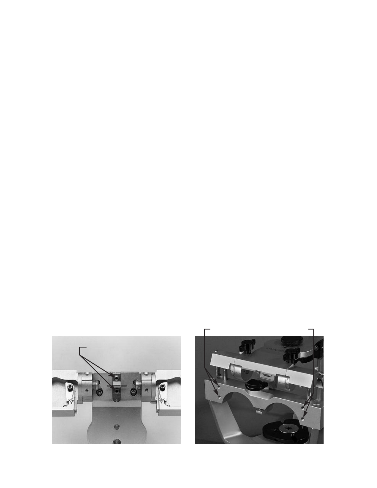
DO NOT ADJUST the factory adjustment screws illustrated in figure 2A. They are for
factory use only. Adjustment of these screws in the field can alter the instrument’s
operation and may require factory repair.
Also the microadjustable adjustment lockscrews illustrated in figure 2B are used to
calibrate the centric relation position of your Mark II articulator to tolerances of plus
or minus one thousandths of an inch from the factory reference position. Adjustment
of these screws can alter the precise factory alignment of your articulator. Do not
modify the setting of these adjustment screws until after you have read this instruction manual and thoroughly understand the function of these adjustment screws as
explained in Appendix D. These microadjustment screws should only be used in conjunction with a Denar
®
Field Inspection Gage to calibrate your articulator.
fig. 2A
fig. 2B
Factory Adjustments
Microadjustment Screws
Page 7

5
I. INTRODUCTION
WHO SHOULD USE THE DÉNAR®MARK II SYSTEM
DOCTORS WHO WANT:
• To mount casts quickly and easily on a semi-adjustable instrument that
mechanically and accurately reproduces mandibular movements.
• To produce restorations by means of checkbite records and/or the func-
tionally generated path (FGP) techniques.
• A useful tool for diagnosis and for the fabrication of restorations when not
utilizing a pantograph and fully adjustable articulator.
• A semi-adjustable articulator with the immediate side shift adjustment
capability.
• Casts mounted on a very rigid articulator in the position of maximum intercuspation.
• To incorporate the benefits of the Denar
®
Two Instrument System.
TECHNICIANS WHO WANT:
• A practical, rigid and easy to use articulator.
• To efficiently produce restorations that require fewer remakes than restorations constructed on articulators of lesser adjustment capability.
• To receive mounted casts.
• To service dentists using the Denar
®
Two-Instrument System.
EDUCATORS WHO WANT:
• An economically priced articulator and facebow for student issue without
violating sound anatomical principles.
• Occlusal instruments that fulfill the needs of all restorative departments.
• To avoid the need for the student having a separate articlulator for each
restoration under construction.
STUDENTS WHO WANT:
• To study Occlusion and the movement of the temporomandibular joint.
A means of progressing to a fully adjustable articulator and pantograph.
Page 8

6
WHY SHOULD THE
MARK II SYSTEM BE USED
Simple and Practical to Use
The Denar®Mark II Articulator and
Facebow System enables the user to
quickly and easily mount casts of a
patient’s teeth on an instrument that is
both an equivalent of their natural relationship and which also can be mechanically programmed to simulate the
mandibular movements of the patient.
To accomplish this mechanical equivalence, the Mark II articulator has adjustment capability to duplicate the more
clinically significant movements of the
mandible. Those condylar paths of
movement of lesser clinical significance
have not been ignored, but instead, are
constructed to average anatomic
dimensions.
Accurate Diagnostic and
Treatment System
The Mark II System is a particularly useful tool for the diagnosis and for the fabrication of restorations when not utilizing
a pantograph and fully adjustable articulator. The simplicity and accuracy with
which the system may be used enables
the user to produce precision occlusal
restorations that require significantly
less in the mouth modifications than
restorations constructed on articulators
of lesser adjustment capability.
Excellent Learning Tool
The Mark II System is built around
sound principles of human anatomy and
is consequently ideal for study of TMJ
characteristics and theories of occlusion. Understanding this system facilitates progress to a fully adjustable articulator as the movements and adjustments are the same.
Constructed with Clinically
Needed Features
The Mark II System is easy to use. The
articulator is rigid with a very positive
centric lock. It is of the Arcon construction with the back designed for maximum lingual visibility to the casts. The
upper and lower bows come apart and
lock together in the open and closed
positions (no rubber bands needed).
The articulator can be placed level in the
upside down position for mounting the
casts without the need of a plastering
stand. The facebow sidearms are independently adjustable and can be located to either the hinge axis or the external auditory meatus (opening) of the
ears.
Economical
The Mark II Articulator which is competitively priced is also two instruments in
one. Not only is it a semiadjustable
articulator with the features described
above, but also because of the micrometer adjustments in the condylar areas,
the condyles can be adjusted three
dimensionally with the Denar
®
Field
Inspection Gage to tolerances of plus or
minus .001 inches (.025 mm) which
allows transfer of the mounted casts to
other Denar
®
articulators. This feature
reduces the need for a separate articulator for every restoration under construction.
Page 9
7
In order to be proficient in the use of the
articulator to diagnose condylar paths of
movement and to fabricate occlusal
restorations, the operator must have
knowledge of:
• The articulator condylar controls
and how to adjust them.
• The proper hand grasps for manipulating the articulator through its
excursive movements.
In this section of this manual we will first
discuss the simple procedure of how to
open and close the articulator properly
and how to operate the centric latch.
Secondly we will discuss the location of
the articulator condylar controls and
how to adjust them. Lastly we will cover
the proper hand grasps for manipulating
the articulator through its excursive
movements. How to adjust the articulator to checkbite records is discussed in
another section of this manual.
ARTICULATOR MANIPULATIONS
To assemble the articulator hold the
upper bow approximately parallel to the
lower bow and simply place it on the
lower bow.
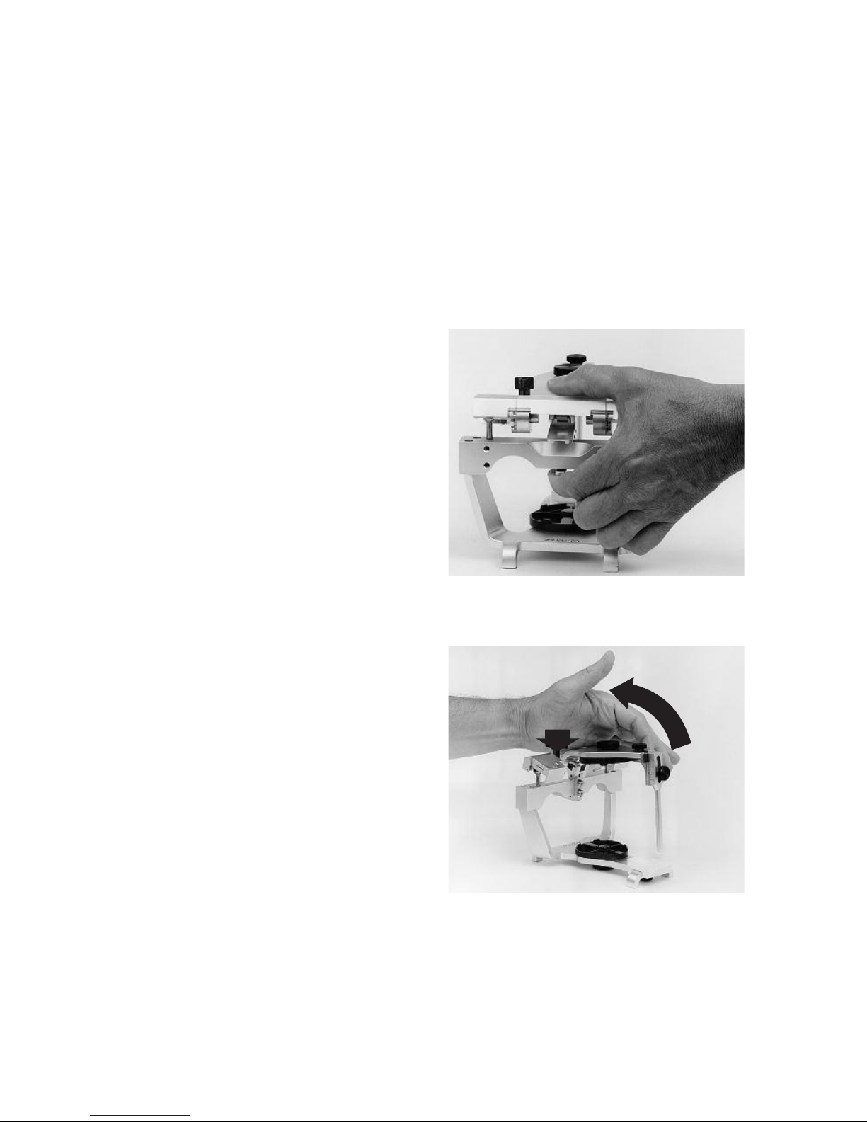
Centric Latch Operation
When the articulator is closed it can be
locked in the centric position by pushing
the centric latch to the down position.
The centric latch is opened by placing
the index finger on the trigger located
underneath the center of the crossbar of
the lower bow and by placing the thumb
on top of the upper bow (fig. 3). Next
apply pressure with the index finger; it
must be released by the trigger. When
the centric latch is open the upper bow
can be removed from the lower bow by
lifting it vertically while maintaining the
upper bow parallel to the lower bow.
To Open the Articulator
Apply downward pressure to the top of
the upper bow over the centric latch and
fossa assemblies with the heel of the
palm of the left hand and simply open
the articulator. The opening movement
of the articulator automatically engages
the centric latch and locks it (fig. 4).
II. THE DÉNAR®MARK II ARTICULATOR
fig. 3
fig. 4
Page 10
8
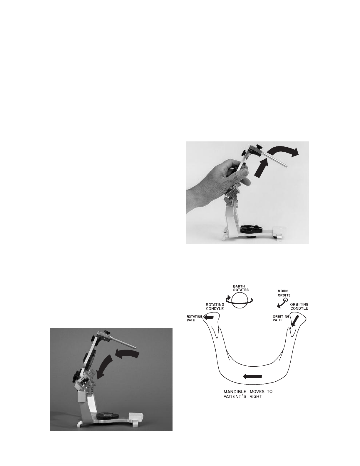
To Lock in the Open Position
When the articulator is opened, the
upper bow can be moved downward
toward the lower bow so that the
condyles move forward in their fossae to
engage the lock open position (fig. 5).
To Close the Articulator
To close the articulator move the upper
bow up and forward to disengage the
lock-open position and close the articulator (fig. 6).
ARTICULATOR ADJUSTMENTS
The articulator is a mechanical equivalent of the lower half of the head
__
a
mechanical jaw so to speak. In order to
discuss the adjustments of the articulator or specifically the fossa controls, it
would be helpful to discuss the condylar
paths of movement of the human
mandible. In a lateral mandibular movement the condyle on the side toward
which the mandible moves is termed the
rotating condyle (fig. 7). The condyle on
the side opposite the side towards
which the mandible moves is termed the
orbiting condyle.
In a lateral mandibular movement the
orbiting condyle moves inward, downward and forward and orbits about the
r
otating condyle which is simultaneously rotating and moving outward during
the mandibular side shift.
orbiting path - the path of movement of the orbiting condyle.
rotating path - the path of movement of the rotating condyle.
protrusive path - the path of
movement of the condyle in a
straight protrusive movement.
fig. 5
fig. 6
fig. 7
Page 11
9
Protrusive Adjustments
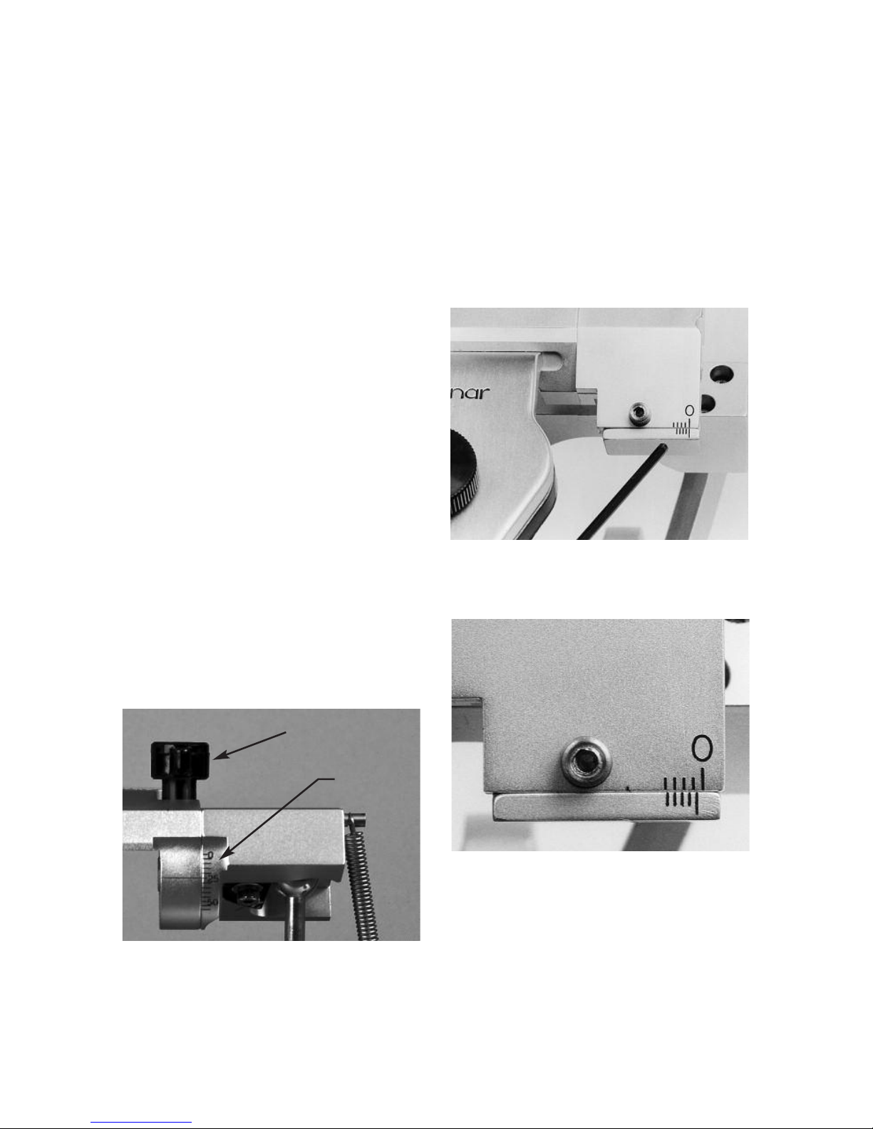
The inclination of the protrusive condylar path can be adjusted by loosening
the protrusive adjustment lockscrew.
The protrusive condylar path inclination
scale is below the protrusive adjustment
lockscrew and is calibrated in increments of 5 degrees (fig. 8).
Immediate Side Shift Adjustment
The medial fossa wall can be displaced
straight medially by means of the immediate side shift adjustment. The scale for
the immediate side shift adjustment is
lateral to the adjustment lock screw on
top of the fossa (fig. 9). The scale is a
Vernier scale calibrated in .2 millimeter
increments. The scale reads medialward
from its lateral extremity.The index in fig.
10 indicates an immediate side shift setting which is more than 0 but less than 1
full millimeter. By reading the Vernier
scale on the lower portion of the scale
medialward from the index it can be
determined that the immediate side shift
is .6 of a millimeter since it is the third
graduation that lines up with a millimeter
graduation on the upper portion of the
scale.
Progressive Side Shift Adjustment
The angle of inclination of the medial
fossa wall to the sagittal plane be
adjusted by loosening the progressive
side shift adjustment lockscrew and
moving the insert from 5 to 15 degrees.
The scale for the progressive side shift
adjustment is anterior to the adjustment
lockscrew and is calibrated in 5 degree
increments. (fig. 11).
fig. 8
fig. 9
fig. 10
Scale
Lockscrew
Page 12
10
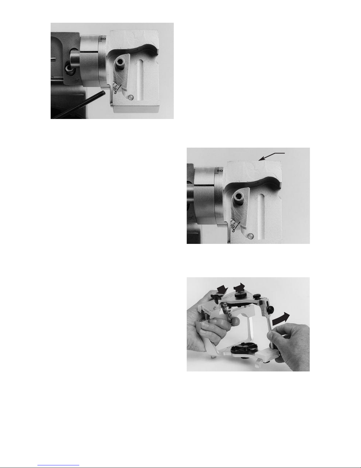
Rear Wall Inclination
The posterior fossa wall of the Mark II
Articulator is nonadjustable but is constructed to average anatomic dimensions. It is inclined posteriorly 25
degrees to allow for a backward movement of the rotating condyle as it moves
outward (fig. 12).
HAND GRASPS
To use the articulator properly the operator must master the proper hand
grasps. A right handed operator curls
the fingers of the left hand under the
mandibular crossbar and places his left
thumb on top of the upper bow (fig. 13).
To effect both left and right lateral excursive movements the left thumb guides
the back of the upper bow while the
forefinger and thumb of the right hand
holds the incisal pin moving it in the
desired direction. These hand grasps
can be best described as the underhand
push__pull grasps and the underhand
protrusive grasps. In order to execute
lateral movements the centric latch
must be open.
Underhand Push Grasps
To effect a right lateral mandibular
movement be sure the latch is open and
move the upper bow to the left. (The left
side of the articulator is the left side of
the instrument as it is viewed from the
rear.) Pressure is applied with the left
thumb to insure the left orbiting condyle
maintains contact with its superior and
medial fossa walls and the right rotating
condyle maintains contact with its superior and rear fossa walls (fig. 13).
fig. 11
fig. 12
fig. 13
Rear
Wall
Page 13
11
Underhand Pull Grasps
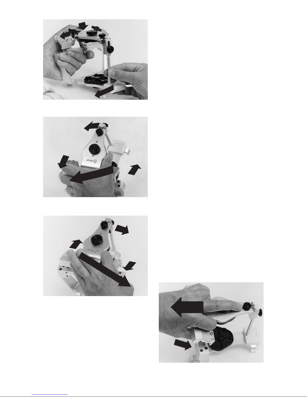
To effect a left lateral mandibular movement the upper bow is moved to the
right and pressure is applied with the
left thumb to insure that the right orbiting condyle maintains contact with its
superior and medial fossa walls and the
left rotating condyle maintains contact
with its superior and rear fossa walls
(fig. 14).
Underhand Protrusive Grasps
(Protrusive Push Grasp)
To effect a straight protrusive movement
the upper bow is moved straight posteriorly with the right hand and the left
thumb is used to apply downward pressure on the back of the upper bow so
that the condyles maintain contact with
their superior fossa walls.
The overhand grasps as contrasted
from the underhand grasps are also
useful in manipulating the articulator
and are required to efficiently set a fully
adjustable articulator to a pantographic
record. Figure 15 illustrates the
Overhand Push Grasp; fig. 16 the
Overhand Pull Grasp, and fig. 17 the
Overhand Protrusive Grasp. When
employing the overhand grasps to
manipulate the articulator be sure to
apply pressure to the back of the articulator to insure that the condyles maintain contact with their respective fossa
bearing surfaces.
fig. 14
fig. 15
fig. 16
fig. 17
Page 14
12
The Dénar®Mark II Articulator is of the
Arcon construction; i.e., the condyles
are attached to mandibular bow and the
fossa assemblies are fixed to the maxillary bow. This construction which is a
facsimile of the anatomical structures,
enables the articulator to more accurately simulate condylar paths of movement. In addition this construction
makes it easy to understand the relation
of condylar paths of movement to
occlusal anatomy.
An understanding of the relationships
which exist between condylar paths of
movement and occlusal anatomy is an
invaluable aid in the use of an articulator
for diagnosis and treatment. The following exercises which utilize the articulator
as a teaching method are helpful to
enable you to quickly understand these
relationships.
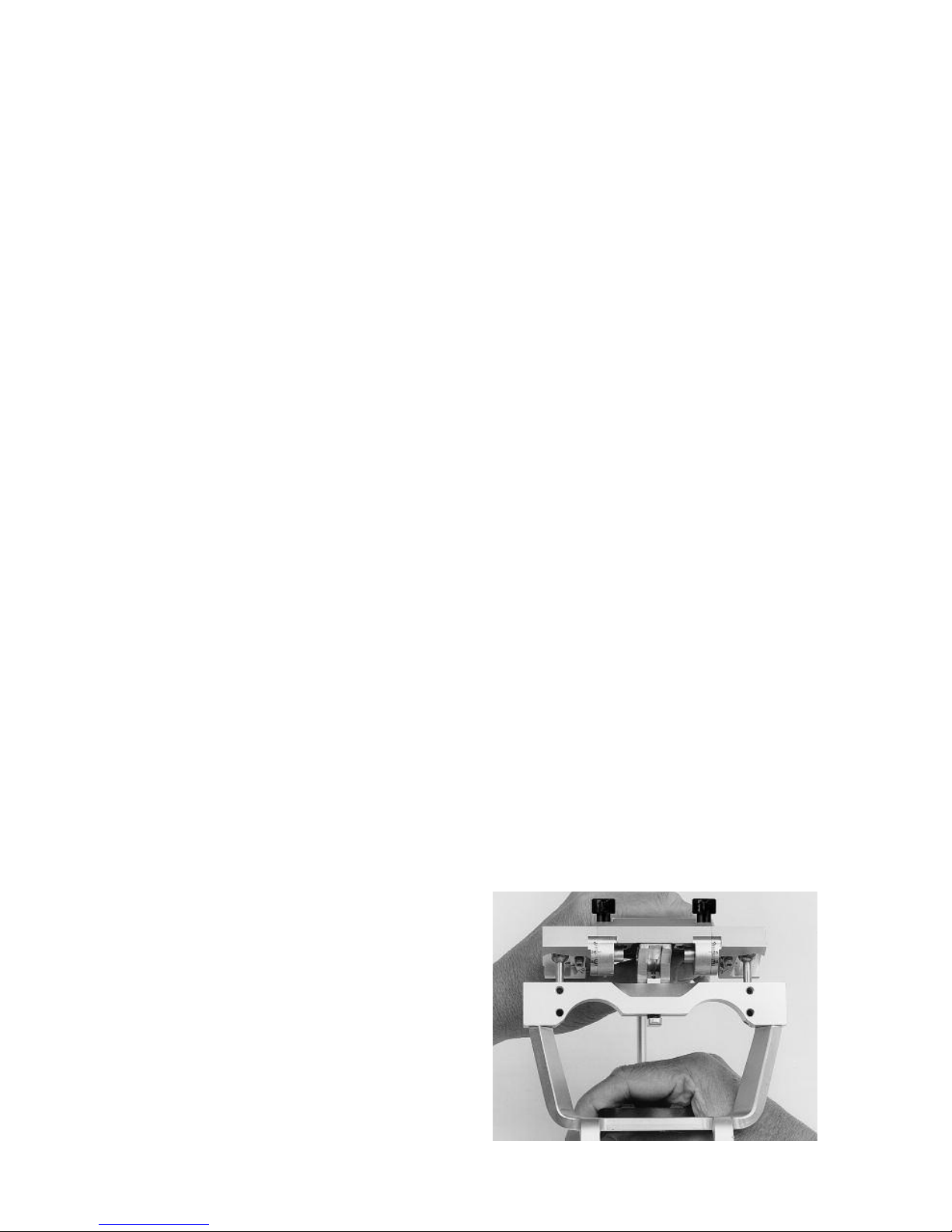
Set the left immediate side shift adjustment to 1 millimeter and left progressive
side shift adjustment to 15 degrees. By
observing the articulator movements
from the back of the articulator it is easy
to understand why the immediate and
progressive side shifts are so named
(fig. 18). Hold the articulator in centric
relation. Since the left medial fossa wall
is set to permit a one millimeter immediate side shift, centric relation is achieved
when the right condyle touches its
medial fossa wall.
Move the articulator in a right lateral
mandibular movement until the left
orbiting condyle contacts its medial
fossa wall and note that the rotating
condyle and mandible move immediate-
ly to the right. As you continue the right
lateral mandibular movement the orbiting condyle move downward, forward
and inward. Note that during this movement of the orbiting condyle the rotating
condyle and mandible move progressively more to the right as the orbiting
condyle advances. Repeat this articulator movement and note that the rotating
condyle moves immediately to the right
and then progressively more to the right
as the orbiting condyle advances.
mandibular side shift (Bennett Shift):
the bodily side shift of the mandible
which occurs during a lateral jaw
movement.
immediate side shift: a mandibular
side shift in which the orbiting condyle
moves essentially straight medially as
it leaves centric relation.
progressive side shift: a mandibular
side shift which occurs at a rate or
amount which is directly proportional
to the forward movement of the orbiting condyle.
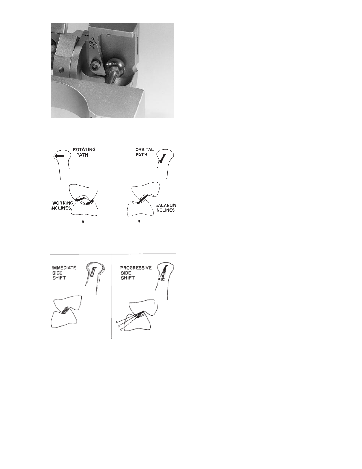
By observing a right lateral mandibular
movement from the front of the articulator you can see that the path of movement of the orbiting condyle (orbiting
path) as it moves inward, downward and
forward is guided by the superior, rear
and medial fossa walls (fig 19). This
condylar path of movement is associated with and has its principal effect on
the balancing inclines of cusps on the
orbiting side (fig. 20B).
III. RELATING CONDYLAR MOVEMENTS
TO OCCLUSAL ANATOMY
fig. 18
Page 15
13
o
f the marginal ridge, fossa, or central
groove of the tooth (fig.21).
An increase of the progressive side shift
movement of the articulator has an effect
of flattening the balancing inclines of
cusps on the orbiting side mediolaterally
(fig. 22).
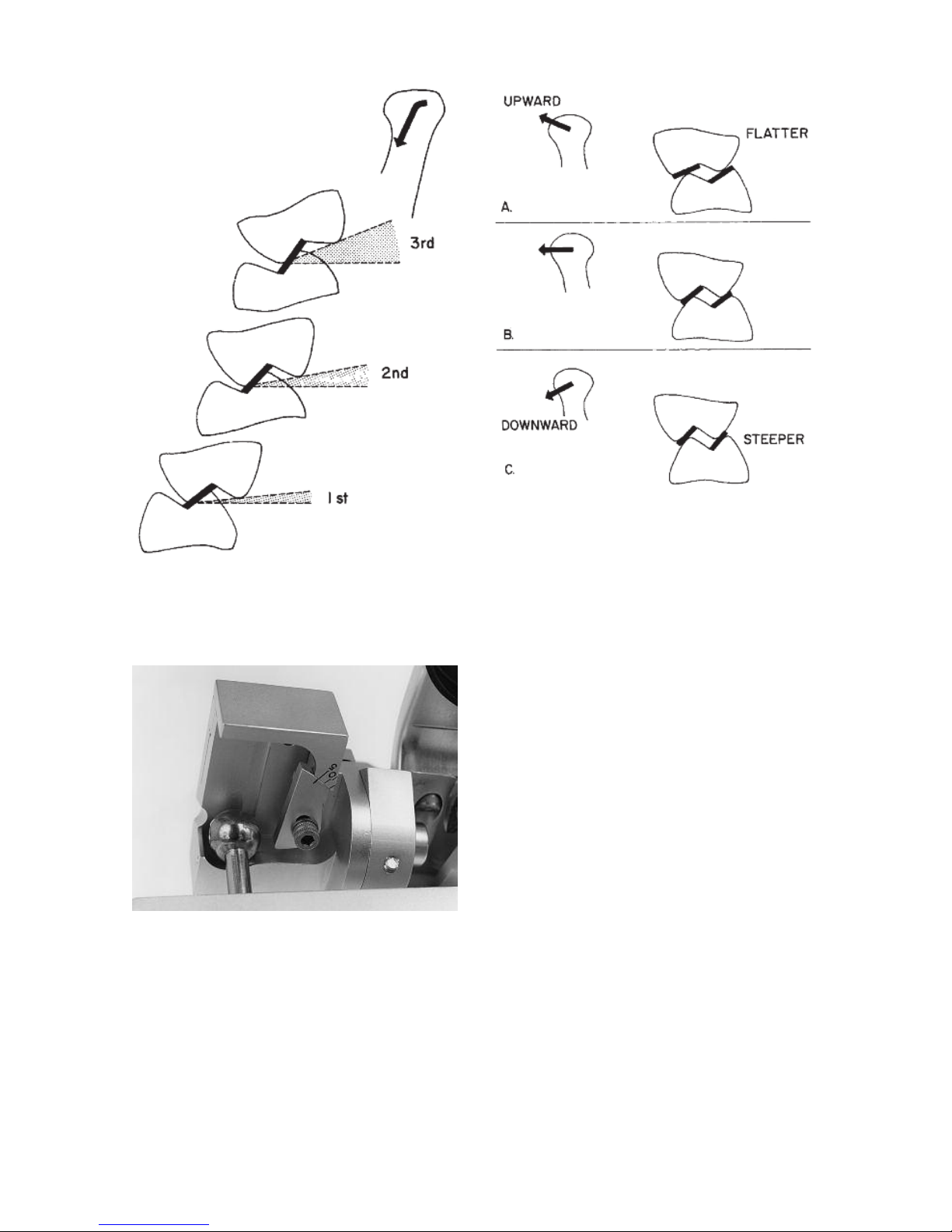
The closer a cuspal incline is to a condylar
path of movement the greater is the influence that condylar control has on occlusal
anatomy. Consequently due to the fact
that the orbiting condyle is moving downward so rapidly as it moves forward, we
observe that as we move more distally in
the dental arches the lingual cusps of
maxillary molars project increasingly
downward and the buccal cusps of
mandibular molars project increasingly
upward to harmonize the occlusion to
condylar paths of movements (fig 23).
Again by observing a right lateral condylar
movement from the front of the articulator
you can see that the path of movement of
the rotating condyle (rotating path) as it
moves outward is guided by the rear and
top fossa walls (fig.24). This path of movement is most closely associated with and
has its principle effect on the working
inclines of cusps on the working side (fig.
20A).
The rotating condylar path may be inclined
upward or downward as the rotating
condyle moves outward. This upward and
downward inclination of the rotating
condylar path in the coronal plane has its
principle influence on the height of the
working inclines of posterior cusps on the
rotating side (fig. 25). If the rotating condylar path is inclined upward the cusps must
be flatter (fig. 25A). If the rotating condylar
path is inclined downward the cusps may
be steeper (fig. 25C). The Mark II Articulator cannot be adjusted to upward or
downward movements of the rotating
condyle.
fig. 19
fig. 20
fig. 21 fig.22
Three articulator adjustments establish the
character of the orbiting path on the articulator: the immediate side shift adjustment,
the progressive side shift adjustment and
the protrusive inclination of the superior
fossa wall.
An increase of the immediate side shift
movement of the articulator has an effect
of increasing the bucco-lingual dimension
Page 16
14
The rotating condylar path may be inclined
forward or backward as the rotating
condyle moves outward. This forward and
backward inclination of the rotating
condylar path in the horizontal plane has
its principle effect on the intermeshing of
the working inclines of cusps on the working side (ridge and groove direction).
The Dénar
®
Mark II Semi-adjustable
Articulator has the rotating condylar path
reset to the average anatomic inclination
(out and backward 25 degrees).
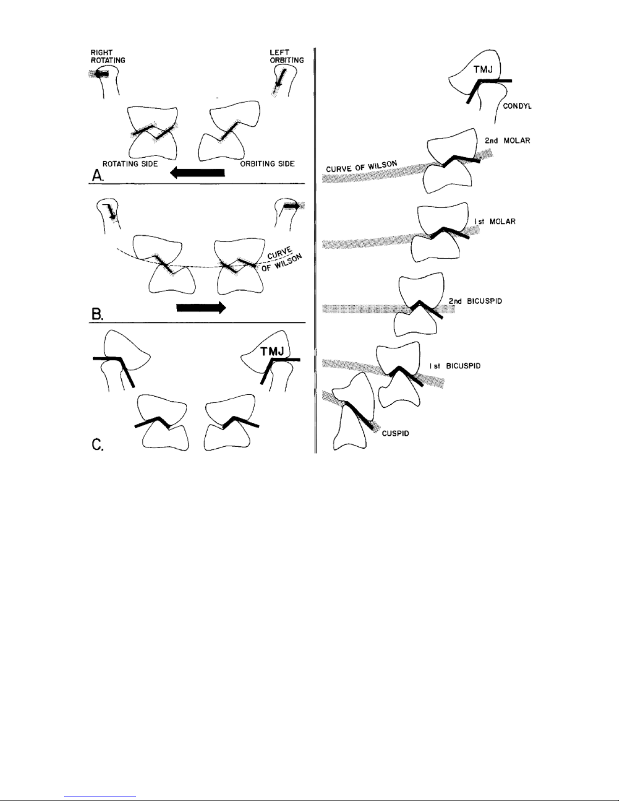
Figure 26A illustrates a frontal view of
molar tooth relations in a right lateral
mandibular movement. Although the rotating condyle moves straight outward the
functioning tooth inclines on the rotating
side have a slight downward inclination
due to the fact that the path of movement
of the orbiting condyle is inclined remarkable downward.
fig. 24
fig. 25
fig. 23
Page 17
15
The closer the functioning tooth incline is
to the condylar path of movement the
more the tooth incline simulates that
condylar path of movement.The interrelating tooth inclines on the orbiting side in
figure 26A have steep inclines to complement the path of movement of the orbiting
condyle.
Figure 26B illustrates a left lateral movement. Due to the fact that the left rotating
condyle is moving straight outward the left
maxillary buccal cusps must be kept short
to allow the left mandibular buccal cusps
to escape. It is this influence of the rotating and orbiting condylar paths on
occlusal anatomy that establishes the
Curve of Wilson. The more posteriorly we
progress in the dental arches the
mandibular teeth take on a greater lingual
inclination and the maxillary teeth take on
a greater buccal inclination to harmonize
occlusal anatomy to condylar paths of
movement (fig. 27). The condyle tracks a
path in its fossa just as a buccal cusp of a
lower molar tracks a path in its fossa on
the occlusal surface of an upper molar. For
all practical purposes in the use of articulators to establish dental articulation, the
temporo-mandibular joint can just be
thought of as another tooth, the fourth
molar__another anatomic control of jaw
movement (figs. 26C and 27).
fig. 26 fig. 27
Page 18
16
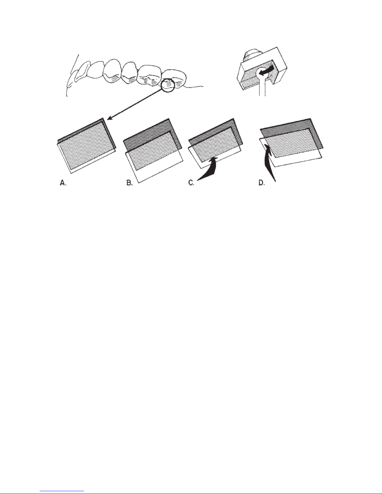
To facilitate a clear understanding of the
relation of the orbiting condylar path to
occlusal anatomy study fig. 28.
Illustrated are the cuspal inclines of the
left bicuspids and molars which are
associated with the orbiting condylar
path. It is the distal aspects of the maxillary lingual cusps’ buccal inclines
(shaded) which interrelate with the
mandibular buccal cusps’ lingual
inclines, mesial aspects. In your mind’s
eye it is helpful to dissect out these cuspal inclines (fig. 28A) and visualize what
influence a change in the character of
the orbiting path on the articulator
would have on these aspects of the
cusps. Three articulator controls establish the character of the orbiting path on
the articulator
__
the immediate side
shift adjustment and the inclination of
the medial and superior fossa walls. Increasing the immediate side shift adjustment on the articulator increases the
clearance between these cuspal inclines
(fig. 28B). Increasing the progressive
side shift movement of the articulator
(increasing the inclination of the medial
fossa wall) flattens the cuspal inclines
mediolaterally (fig. 28C). A decrease of
the inclination of the superior fossa wall
flattens the cuspal inclines anterio-posteriorly (fig. 28D).
fig. 28
Page 19
17
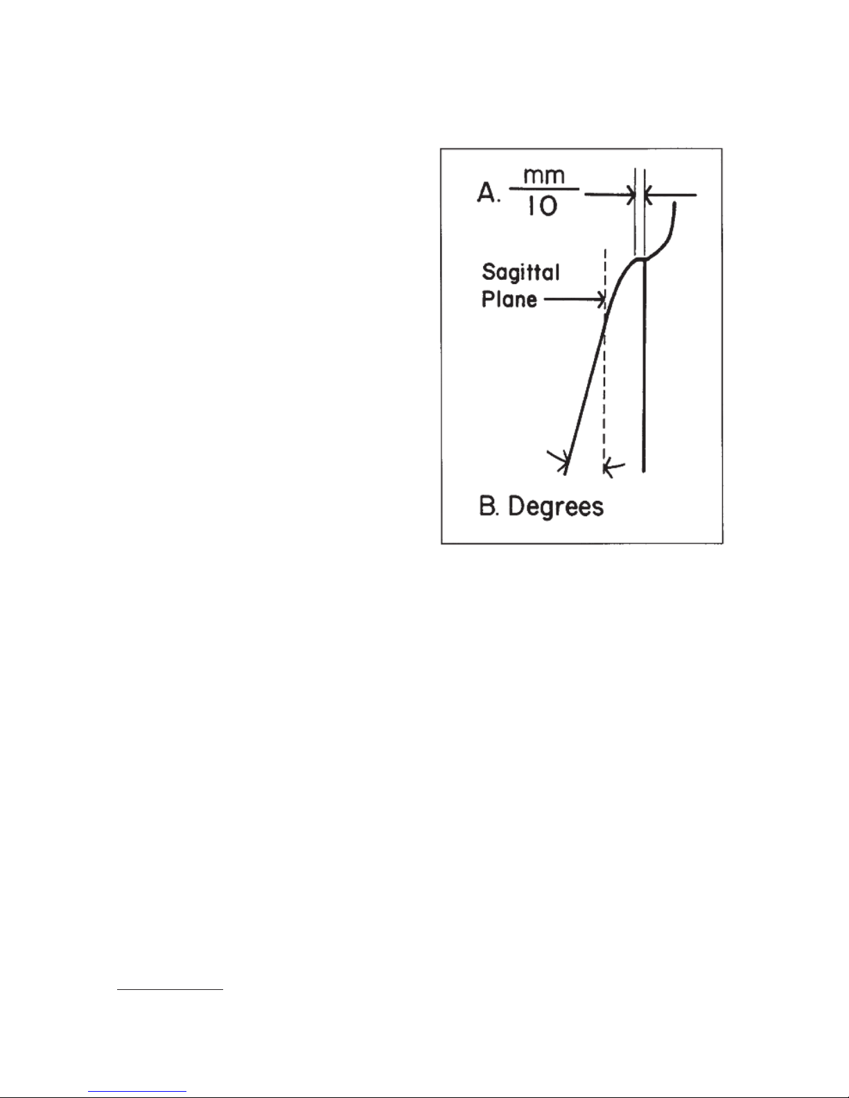
It should be noted that unlike most
semi-adjustable articulators the Denar
®
Mark II Semi-adjustable Articulator has
the capability of more accurately simulating the mandibular side shift (Bennett
Shift) by more accurately simulating the
component condylar movements: the
immediate side shift and the progressive
shift. The immediate side shift is
expressed in units of tenths of a millimeter (fig. 29A). The progressive side shift
is expressed in degrees (fig. 29B).
The immediate side shift of the mandible
has primary influence on the width of
the central groove of posterior teeth.The
progressive side shift has its principal
influence on the balancing inclines of
posterior cusps on the orbiting side and
on the direction of the ridges and
grooves of posterior teeth, primarily on
the orbiting side.
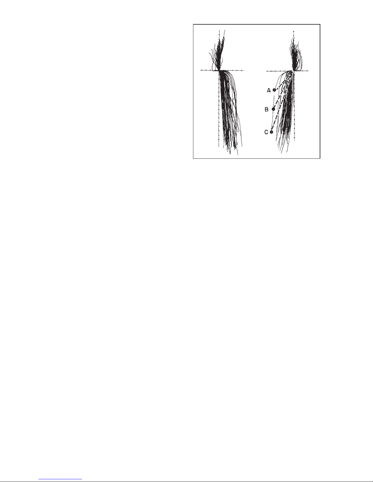
Figure 30 illustrates the protrusive, orbiting and rotating path records of the right
and left temporomandibular joints of 50
patients (100 TMJ records). 1 The X and
Y axes are calibrated in increments of 1
millimeter. You will note that the orbiting
path is divided essentially into two components: immediate side shift and progressive side shift. Furthermore with few
exceptions once the immediate side
shift has occurred the progressive side
shift records are approximately parallel
to each other and are inclined approximately five to seven degrees to the
sagittal plane. The biggest variable is
the immediate side shift component of
the orbiting path.
Points A, B and C on one orbiting path
represent three different condylar positions at which lateral checkbite positional records may be taken on one patient.
It should be noted that if an articulator
possessing a progressive side shift and
not an immediate side shift adjustment
were set to each of the three condylar
positions A, B and C as shown in fig. 30.
It would produce three different progressive side shift inclinations corresponding to the three dotted lines in figure 30
__
all of which inclinations would be
wrong. On the other hand, if an articulator possessing a progressive as well as
an immediate side shift adjustment
IV. THE IMMEDIATE AND PROGRESSIVE SIDE
SHIFT ADJUSTMENT (Bennett Shift)
fig. 29
1. Lundeen, Harry C. and Wirth, Carl G.: Condylar Movement Patterns Engraved in Plastic Blocks,
J. Prothet. Dent. December 1973.
Pages 870-875.
Page 20
18
(Dénar®Mark II) were adjusted so that
the progressive side shift was pre-set to
the average anatomic dimension of six
degrees, one immediate side shift
adjustment setting would intersect with
all three condylar position checkbite
records (A, B, and C) which remarkably
reduce the amount of irritation that otherwise might be introduced in the occlusion. Therefore when adjusting the Mark
II Articulator to lateral checkbite records,
always set the progressive side shift
adjustment to the 6˚ average anatomic
dimension for this diagnostic procedure.
fig. 30
Page 21
19
The Dénar®Mark II Facebow/Earbow is
used to register the correct position for
the patient’s maxillary cast to be mounted in the articulator. In other words, the
facebow/earbow records the relation of
the patient’s maxillary dental structures
to the horizontal reference plane and
transfers this relationship to the articulator.
The use of the Denar
®
Facebow/ Earbow
involves three overall procedures:
A. Locating three reference points
on the patient’s face
B. Assembling the face-
bow/earbow on the patient
C. Transferring the face-
bow/earbow to the articulator
The detailed steps of each of these
three procedures is as follows.
LOCATING THREE REFERENCE
POINTS ON THE PATIENT’S FACE
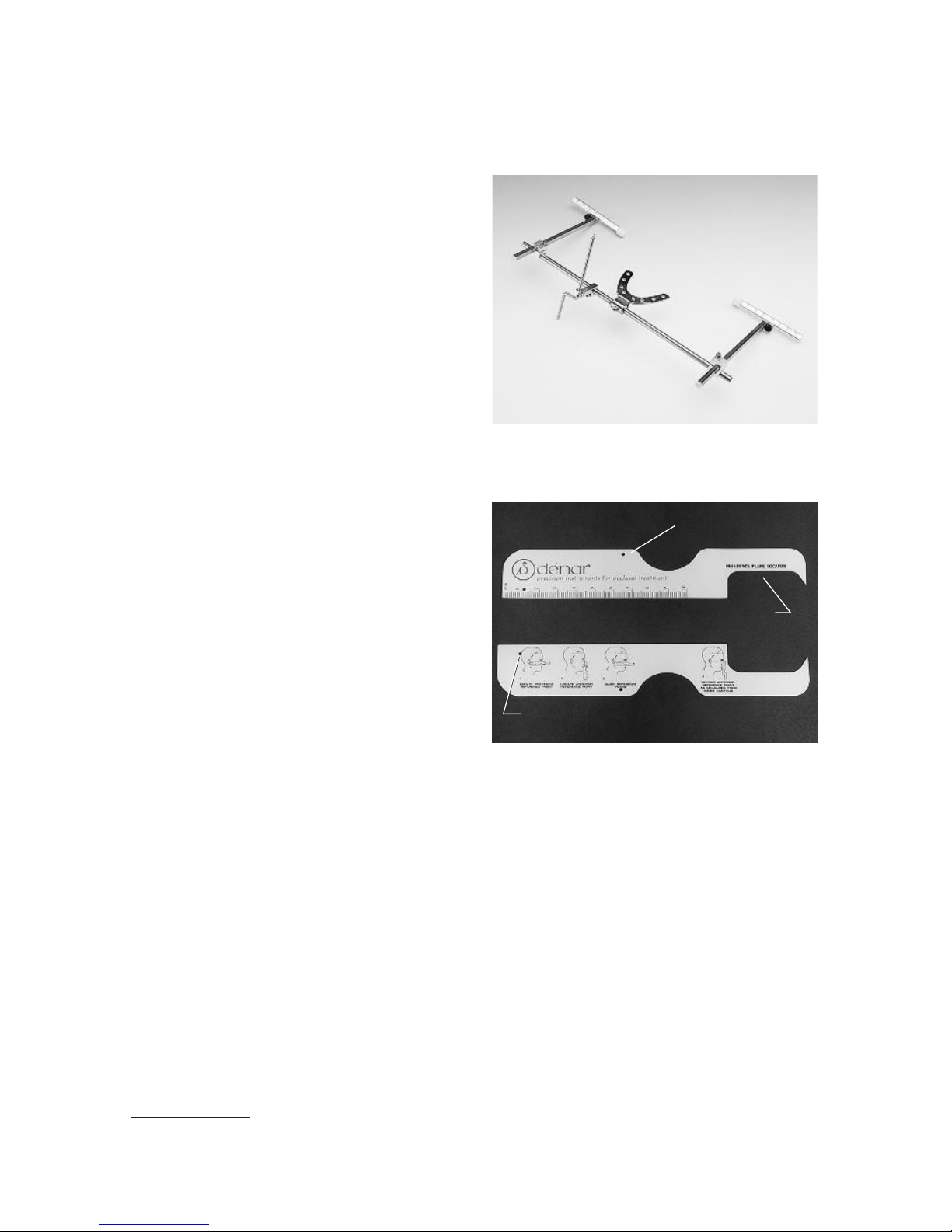
The components of the facebow kit
needed are: the reference plane locator
and reference plane marker. These two
items are used to locate three anatomical reference points on the patient’s
face. Of these three points, two are posterior and one is anterior.
There are two means of locating the
posterior points. The first is by precise
location of the terminal hinge axis with a
hinge axis locator.
1
The second means is
by locating the points by average
anatomical measurement, which is simpler and faster, and is the procedure
described in this section of this manual.
V. THE DÉNAR®MARK II
FACEBOW/EARBOW (Model D31AB)
1. Other reference material must be consulted for detailed instructions on how to precisely locate
the terminal hinge axis position (i.e., the “Denar
®
Procedures Manual__Procedures for Occlusal
Treatment” or the “Denar
®
Office Tutor” ).
´
´
fig. 31
fig. 32
´
REFERENCE ROD INDEX
MILLIMETER SCALE
43mm
NOTCH
POSTERIOR REFERENCE POINT HOLE
Page 22
20
Average measurement may be used to
locate the posterior reference points
whenever you do not vary the vertical
dimension of the casts on the articulator, or, in other words, when the
mandibular cast is to be transferred to
the articulator by means of an interocclusal record taken at the correct vertical dimension and the vertical dimension is not going to be changed on the
articulator.
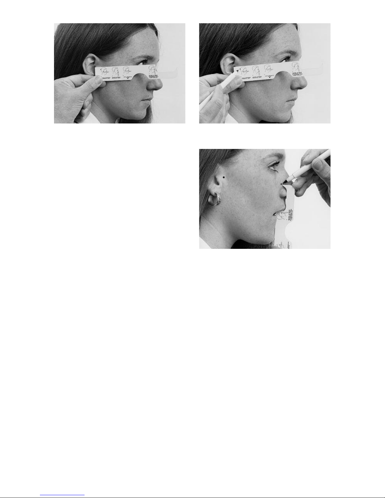
Place the “reference plane locator”
along the right side of your patient’s
face. It should extend from the middle of
the upper border of the external auditory meatus to the “outer canthus” of the
eye. In other words, the reference plane
locator should extend from the middle
of the upper border of the ear-hole to
the outer corner of the eye (fig. 33).
There is a small hole in the upper posterior area of the locator. Once the locator
is in position on the patient’s face, use
your felt-tipped pen to gently mark
through the hole onto the face (fig. 34).
Make the mark on both sides of the
patient’s face.
The position of the “anterior reference
point” is measured up 43 millimeters
from the “incisal edges” of the central or
lateral incisor, toward the inner corner of
the eye. The notched out area of the
“reference plane locator” is used to
make this measurement. The notch is 43
millimeters in length.
Simply rest the lower edge of the notch
on the incisal edge of the right central or
lateral incisor. On an edentulous patient
measure up from the low lip line. The
“low lip line” is the lower border of the
upper lip when it is in repose. In either
case, mark the anterior reference point
below the inner canthus of the right eye
where the top point of the locator touches the patient’s face (fig. 35).
fig. 33 fig. 34
fig. 35
Page 23
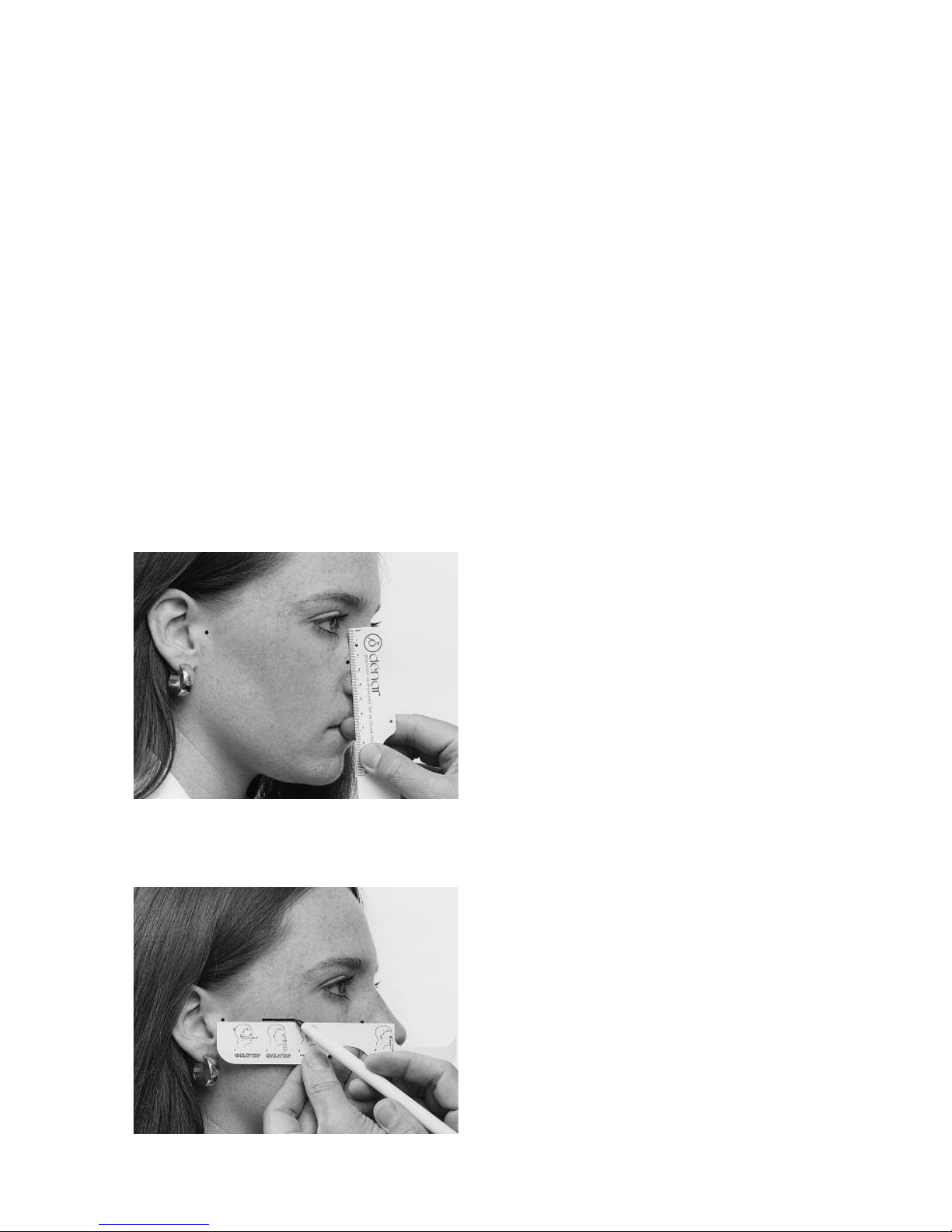
21
M
easure the distance between the anterior reference point and the inner canthus of the eye (fig. 36). Record this
measurement in the patient’s file for
future reference. In this way, if the anterior teeth are removed or modified the
same anterior reference point can be
located by measuring downward from
the fixed immovable inner canthus of
the eye.
The final step is to mark the “horizontal
reference plane” on the right side of the
patient’s face. Just line the ruler up
between the anterior and posterior reference points. Hold the ruler so that it is
just out of contact with the patient's
skin, so that it will not displace the skin,
and then draw a short line on the side of
the face. This line represents the “horizontal reference plane” (fig. 37).
Y
ou will therefore notice that the horizontal reference plane is identified on
the face of the patient by two posterior
reference points in the area of the terminal hinge axis and one anterior reference
point located 43 millimeters above the
incisal edges of the maxillary anterior
teeth or low lip line of the patient.
MAKING THE FACEBOW/
EARBOW REGISTRATION
(Assembling the Facebow/Earbow
on the patient)
The components of the kit needed are:
the bitefork, anterior crossbar, reference
rod, reference rod clamp, and the right
and left facebow side arms with nylon
earplugs at the ends of the posterior reference slides (fig. 31).
Attach the bite fork to the crossbar so
the reference rod clamp is to the
patient’s right, and the u-shaped part in
the bite fork is above the crossbar (fig.
38). Then load the upper surface of the
bite fork with two thicknesses of baseplate wax (fig. 39). Soften the wax to a
dead soft consistency in warm water or
an open flame, and then put the loaded
bite fork in the patient’s mouth to get a
light indexing impression of the maxillary teeth. When the bite fork is first
placed in the mouth, be certain to line
up the crossbar so that it is parallel to
the coronal and horizontal planes of the
patient. Also be sure to be careful not to
depress or displace any mobile teeth
__
all you really need is a slight impression
of the tips of the cusps (fig. 40).
Remove the bite fork from the patient’s
mouth, and place the maxillary cast, if
available, in the bite fork to confirm
accurate seating. If the maxillary cast
seats accurately in the bite fork, you can
now begin assembly of the facebow
record.
Put the bite fork assembly back in the
patient’s mouth, indexing it to the maxillary teeth. Have the patient hold the bite
fig. 36
fig. 37
Page 24
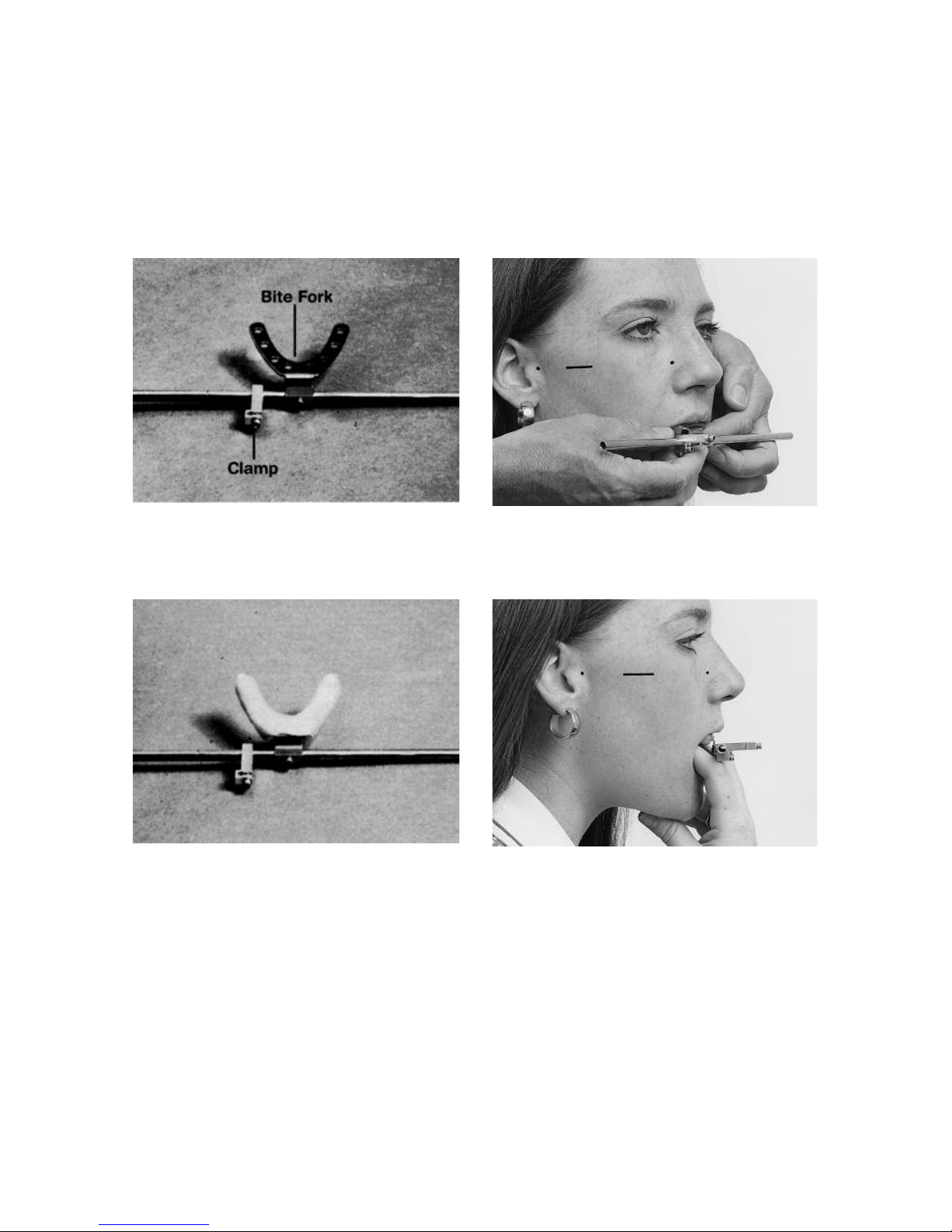
22
f
ork in place (fig. 41). This can be done
most conveniently by having the patient
bite on the index and middle fingers of
the left hand. Alternatively position cotton rolls on the occlusal surface of the
lower posterior teeth and instruct the
p
atient to maintain the bite fork in place
with gentle biting pressure.
Adjust the reference rod clamp so it is
parallel to the reference plane marked
on the patient’s face (fig. 42).
fig. 38 fig. 40
fig. 39 fig. 41
Page 25
23
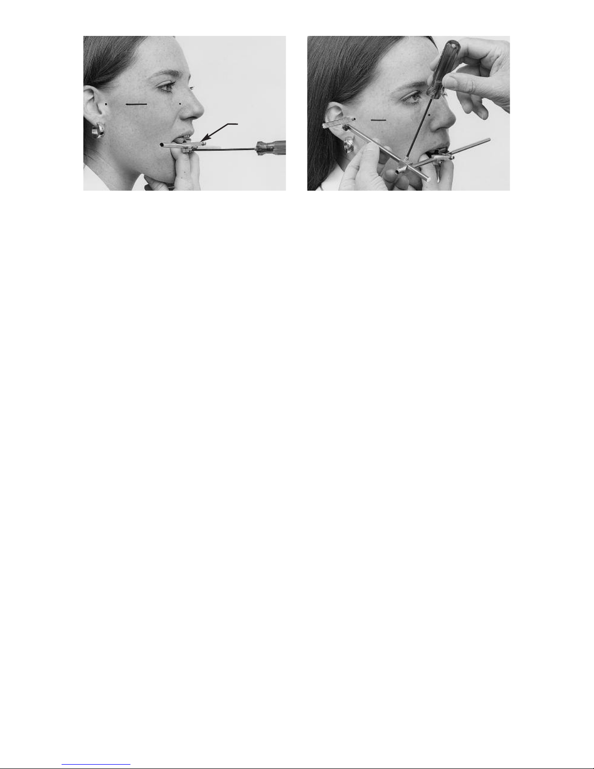
At this point you will be ready to attach
the facebow side arms. Note that they
are marked right and left and refer to the
patient’s right and left. Make sure that
the scales on the posterior reference
slides are adjusted to their zero positions.
A. Facebow Application
Remove the nylon earpieces on both
the posterior reference slides and
begin the attaching of the side arms
(fig. 43). First you will need to locate
the right side arm on the crossbar so
that the lockscrew on the crossbar
clamp faces upward and the posterior reference pin at the end of the
posterior reference slide lightly
touches the posterior reference
point. Secure the side arm clamp to
the anterior crossbar. Then attach
the left side arm similarly.
B. Earbow Application
Make sure the nylon earpieces are
on both posterior reference slides.
Position the right arm on the crossbar so that the lockscrew on the
crossbar clamp faces upward and
the nylon earpiece fits snugly in the
external auditory meatus. Secure the
side arm clamp tightly and attach the
left side arm similarly.
At this point the facebow/earbow
records the relationship of the maxillary
dental structure to the posterior reference points. The only thing remaining to
be done is to relate the maxillary dental
structures to the anterior reference
point.
Insert the reference rod into its clamp
bringing it up from underneath the
clamp, with the step in the rod facing
toward the patient’s right (fig. 44). Hold
the reference plane locator between the
thumb and index finger of your left hand
so that you can read the instructions on
the back. The semilunar notch on the
locator’s inferior surface should be
placed over the bridge of the nose. Note
the small hole in the center of the locator. Turn the locator down flat so that the
instruction side faces downward and
index the hole on the locator over the
small dowel-like projection on the upper
extremity of the reference rod. Position
your eye approximately six inches in
front of the locator. By line of sight
adjust the locator by inclining it anterioposteriorly and medio-laterally until a
projection of its broad surfaces pass
through both posterior reference points
as indicated by the posterior reference
slides (fig. 45). At this time the anterior
reference point marked on the patient’s
face may be above or below the reference plane locator.
Adjust the height of the reference rod so
that a projection of the locator’s broad
fig. 42 fig. 43
Clamp
Page 26
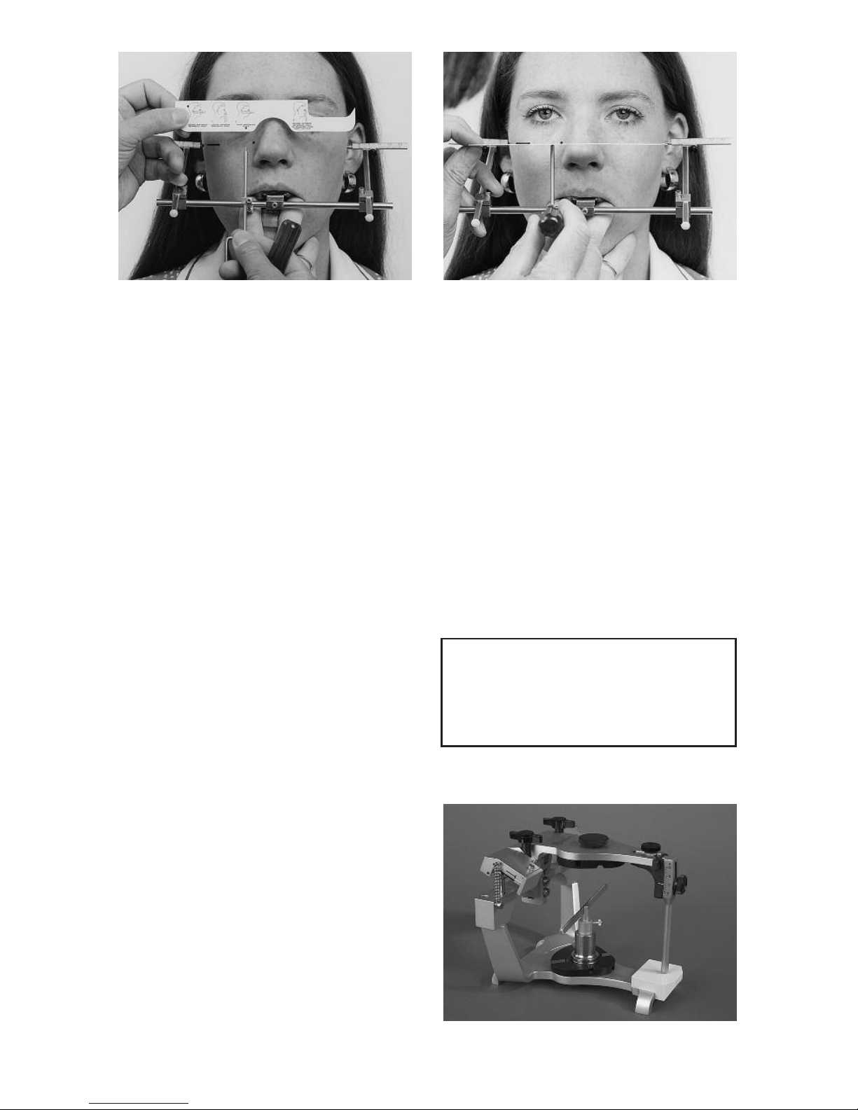
24
surfaces passes through the anterior
reference point as well as the posterior
reference points (fig. 45). Then with your
left hand pull the locator to the side so
that the reference rod is wedged in its
clamp. With the wrench in your right
hand tighten the clamp to secure the
reference rod in its support.
OPTIONAL The Anterior Reference
Pointer, Part No. D145, shown on page
58, is an optional accessory to the facebow which may be used in lieu of the reference plane locator (ruler) to adjust the
reference rod to the anterior reference
point marked on the patient’s face.
Now slightly retract the posterior reference slides so that they will not scratch
the patient’s face or hurt the ears as you
remove the facebow/earbow assembly
from the patient’s face. Once removed
repostion the slides to their original zero
positions. The facebow can now be
used to accurately locate the maxillary
cast on the articulator.
TRANSFERRING THE FACEBOW/
EARBOW TO THE ARTICULATOR
To prepare the articulator to accept the
facebow, set the immediate side shift
adjustments to zero, the progressive
side shifts to 5 degrees and protrusive
condylar paths to 30 degrees. The vertical dimension of the incisal pin should
also be set to zero (fig. 46).
Next secure a mounting plate to the
upper bow of the articulator and a maxillary cast support to the lower bow (fig.
47). The maxillary cast support fits onto
the lower bow of the articulator in lieu of
a mounting plate. It will help support the
weight of the cast and prevent deflection of the facebow.
When attaching a mounting plate to the
bow of an articulator always turn the
mounting plate in the same direction the
lockscrew is turned as the mounting plate
is secured to the articulator bow. (fig. 48).
fig. 44 fig. 45
fig. 47
fig. 46
Progressive Side Shift 5˚
Protrusive Adjustment 30˚
Incisal Pin & Table 0˚
All Other Settings 0˚
Page 27
25
A. Facebow Transfer
If the facebow/earbow is used as a facebow (the posterior reference points are
oriented to the posterior reference
points marked on the side of the
patient’s face in the area of the terminal
hinge axis) the facebow will be attached
to the articulator by indexing the posterior reference pins into the facebow
indexes on the lateral aspects of the
condyles (fig. 50).
A. Earbow Transfer
If the facebow/earbow is used as an
earbow the nylon earplugs are removed
for attachment of the bow to the articulator and the posterior reference pins
are indexed into the earbow index holes
on the lateral aspects of the fossae (fig.
50).
If the facebow was oriented to the
patient to posterior reference points
located precisely with a hinge axis locator, marked readjustment of the posterior reference slides of the facebow to
accommodate it to the articulator could
introduce a slight mounting error. In
order to minimize this error, mounting
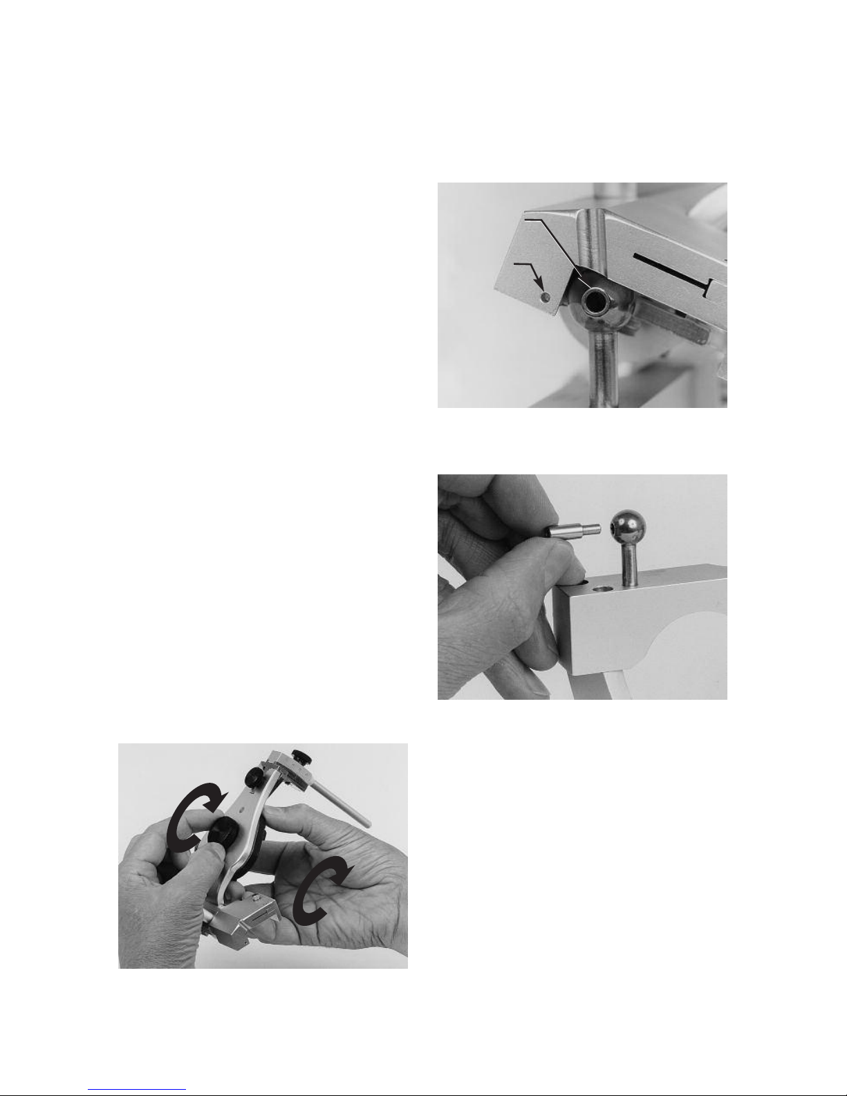
studs are inserted into the lateral
aspects of the condylar elements to
minimize the amount of adjustment of
the posterior reference slides (fig. 51).
A
ttach the facebow (or earbow) assembly to the articulator by equally adjusting
both posterior reference slides so that
both scales give the same reading when
the posterior reference pins are firmly
fig. 48
fig. 50
fig. 51
Facebow
Index
Earbow
Index
Page 28
26
s
eated in their respective condylar or
earbow index holes. This can be done
most conveniently by indexing both
posterior reference pins in their respective holes. Observe the setting to which
the slides are adjusted. The sum of
these settings divided by 2 is the setting
to which the posterior reference slides
are adjusted for proper transfer of the
facebow to the articulator. (For example,
the sum of +30 and -10+=20 divided by
2=+10.)
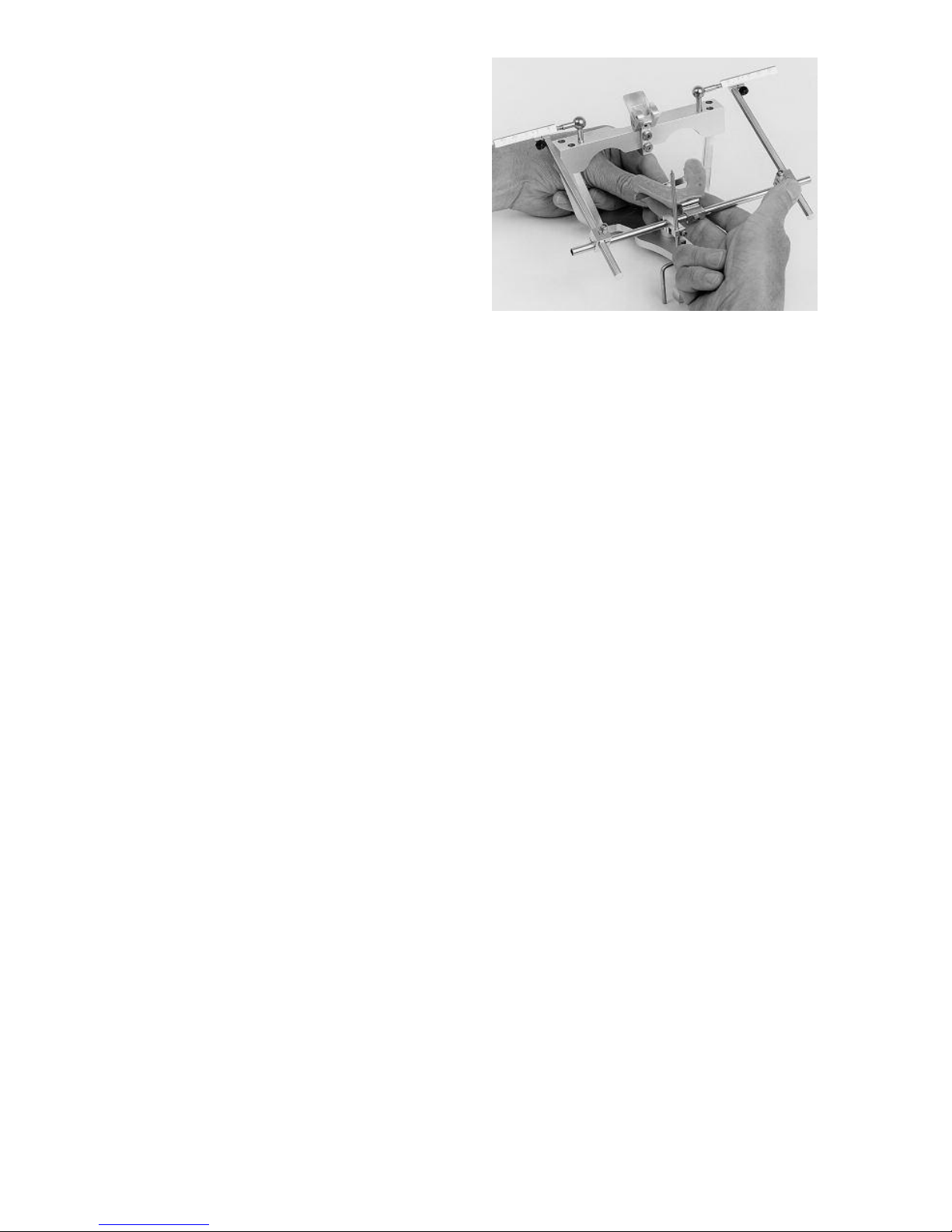
The maxillary cast support is adjusted
so that the support crossbar firmly contacts the undersurface of the bitefork
without lifting the reference rod from its
bearing surface (fig. 52).
fig. 52
Page 29
27
The procedures for constructing casts
are not discussed in this manual. Once
you have obtained impressions of the
upper and lower arches for purposes of
constructing the casts, you will in addition require four interocclusal checkbite
records in order to mount the mandibular cast in the articulator and to adjust
the fossa controls of the articulator: a
centric relation record, one right and
one left lateral checkbite record and a
protrusive record. The selection of the
method and material used for obtaining
these records is left to the preference of
the operator. One recommended checkbite procedure is presented in Appendix
A of this manual.
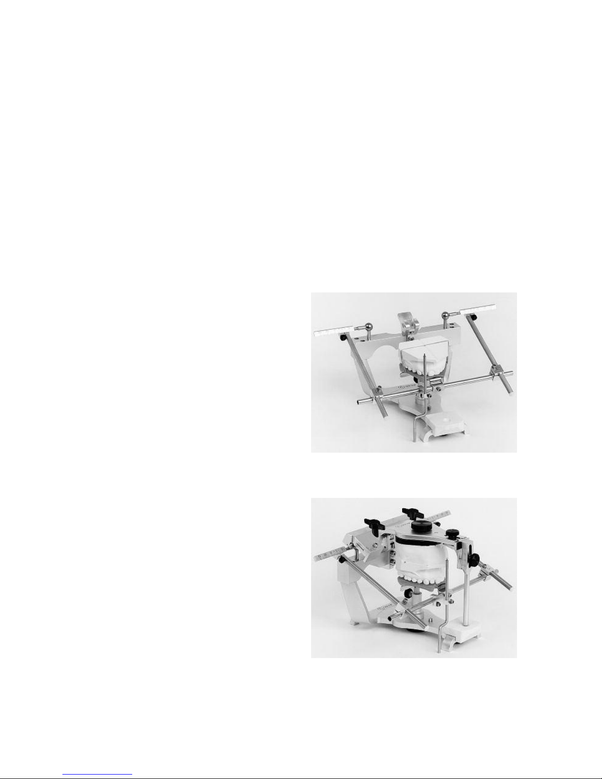
THE MAXILLARY CAST
First secure the maxillary cast to the bite
fork with sticky wax or with a light elastic band (fig. 53).
With the mounting plate secured in the
upper bow of the articulator, fill the
mounting plate with stone and also
apply stone to the top of the cast. Be
sure the mounting stone completely fills
the recesses of the mounting plate. The
cast is secured to the mounting plate
with a “one mix” or “two mix” procedure.
“One Mix” Procedure Use one mix
of fast set mounting stone to secure
the maxillary cast to the mounting
plate. With a little experience a neat
mounting can be achieved with this
technique.
“Two Mix” Procedure Use one mix
of fast set stone to completely fill the
recesses of the mounting plate and
to tack the cast to the mounting
plate. After the stone is set, remove
the mounted cast from the articulator and use a second mix of fast set
stone to complete the mounting. The
“two mix” procedure is recommended to easily obtain a neat mounting.
Bring the upper bow down on top of the
cast, so the stone bonds the two
together. Now engage the centric latch.
Throughout this procedure be sure that
the condyles maintain centric relation
and the incisal pin touches the incisal
platform (fig. 54). Once the stone has
set, remove the maxillary cast support
from the articulator.
VI. MOUNTING THE CASTS IN THE ARTICULATOR
fig. 53
fig. 54
Page 30
28
W
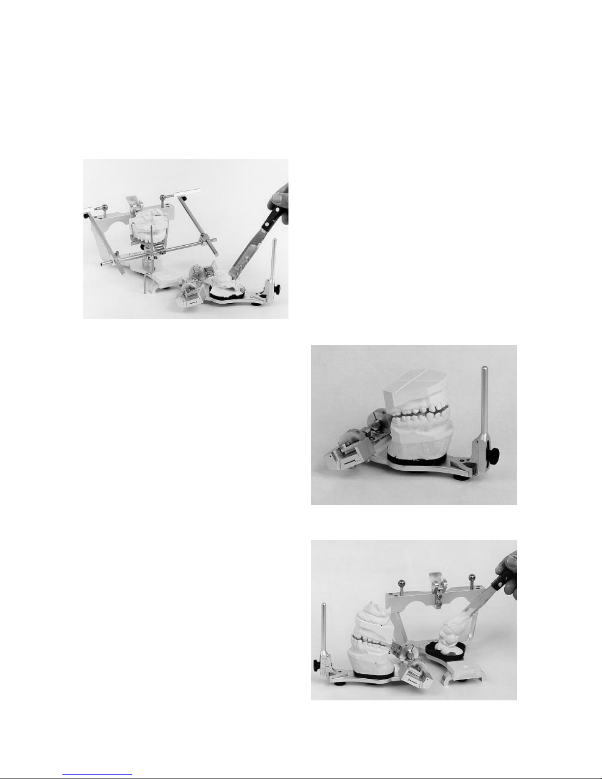
ith the facebow application (not the
earbow) it is usually easier to fill the
mounting plate with stone and stock a
pile of mounting stone on the maxillary
cast if the maxillary bow is removed and
inverted on the working surface beside
the facebow-mandibular bow assembly
(fig. 55).
THE MANDIBULAR CAST
With the maxillary cast in the articulator,
separate the upper bow from the lower
bow and turn the upper bow upside
down. Orient the mandibular cast to the
maxillary cast by accurately seating and
luting the centric relation record
between the two casts. Secure the
casts assembly with sticky wax or a light
rubber band (fig. 56).
If the centric relation record was taken
at an increased vertical dimension, estimate the distance the vertical dimension
was increased by the centric relation
record and adjust the vertical dimension
of the incisal pin to this dimension.
Fill the lower bow mounting plate with
fast set stone and put an appropriate
amount of stone on the base of the
mandibular cast (fig. 57). Then invert the
lower bow and seat it on top of the
upper bow. Make sure the condyles are
seated in their fossae (fig. 58). Make
sure that the incisal table is on the
incisal pin. Lock the centric latch to its
most closed portion. Complete the
m
ounting of the mandibular cast with
the “one mix” or “two mix” procedure
previously described.
An alternate method of mounting the
mandibular cast is to first load the
mounting plate with fast set stone and
then put an appropriate amount of stone
on the base of the mandibular cast.
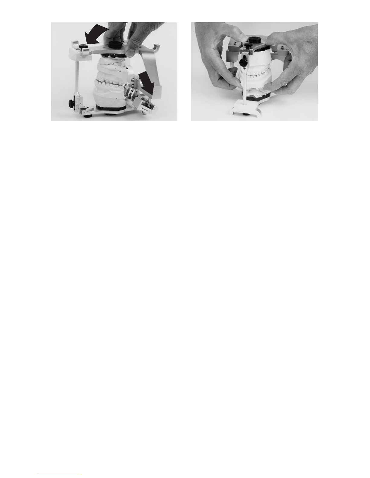
Next grasp the maxillary bow and support the centrically related casts with the
thumb, index and middle fingers as illustrated in fig. 59. Invert the maxillary
bow-casts assembly over the mandibular bow and firmly seat the condyles in
their fossae. Close the articulator until
the incisal pin contacts the incisal table.
While maintaining this hand grasp have
an assistant move the centric latch to its
most closed position. After the initial set
of the mounting stone has occurred to
fig. 55
fig. 56
fig. 57
Page 31
29
support the mandibular cast, the fingers
are removed from the assembly. Subsequently the mounted mandibular cast
is removed and the mounting is completed with the “two mix” method.
A recommended procedure is to initially
obtain three centric relation check-bite
records to verify the accuracy of the
centric relation mounting as detailed in
Appendix B of this manual.
fig. 58 fig. 59
Page 32
30
To set the articulator to checkbite
records you will need the articulator to
which have been mounted both the
maxillary and mandibular casts. You will
also need right and left lateral checkbite
records and a protrusive record.
(Alternate techniques require fewer
checkbite records and use average
anatomical dimensions for those condylar path dimensions not recorded and
measured.)
In this section we will first diagnose and
record the characteristics of the
patient’s orbiting paths of movement
from the two lateral checkbite records,
and then diagnose and record the inclinations of the protrusive condylar paths
with protrusive checkbite record.
SIMULATING THE ORBITING
CONDYLAR PATH
First remove the maxillary bow from the
articulator and confirm that both progressive side shift adjustments are set
to the 6˚ settings. The reason for this
setting was explained in the previous
section on the Immediate and
Progressive Side Shift Adjustments.
Next loosen the protrusive and immediate side shift adjustment lockscrews on
both sides of the articulator (a total of
four screws). Set the protrusive condylar
paths to 0˚ and move the medial fossa
walls medially to the limit of their range
of movement. Do not tighten the
lockscrews.
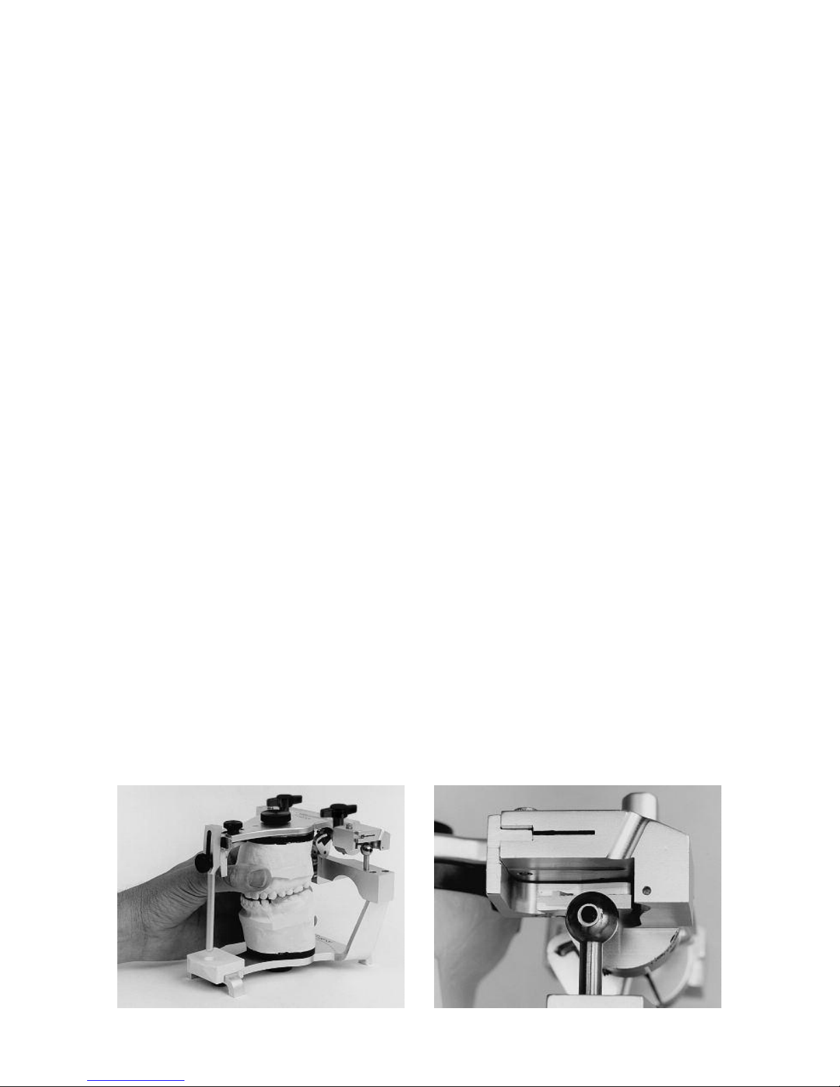
Seat the right lateral checkbite record
on the mandibular casts. Firmly seat the
maxillary cast in the checkbite record by
grasping the maxillary cast as illustrated
in fig. 60 or by applying pressure to the
top of the upper bow to immobilize the
maxillary cast (due to the fact that the
Mark II Articulator has the rotating
condylar paths built to average anatomic dimensions, impingement of the rotating condyle against its rear and superior
fossa walls may sometimes prevent
complete seating of the maxillary cast in
the checkbite record). At this time the
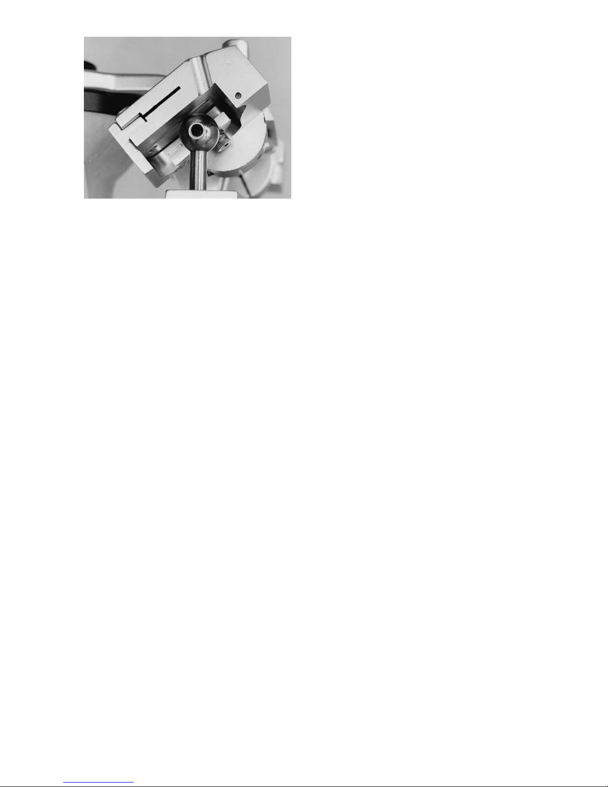
left condyle is positioned inward, downward, and forward from its centric related position (fig. 61). Increase the inclination of the left protrusive condylar path
until the superior wall of the fossa contacts the top of the condyle (fig. 62).
Secure the protrusive condylar path in
this position by tightening the
lockscrew.
Move the left medial fossa wall laterally
until it contacts the condylar element.
VII. SETTING THE ARTICULATOR
TO CHECKBITE RECORDS
fig. 60 fig. 61
Page 33
31
Lock the immediate side shift adjustment lockscrew.
Note: These three articulator adjustments, the immediate side shift, the progressive side shift and the protrusive
inclination of the superior fossa wall
establish the character of the orbiting
path on the left side of the articulator.
Use the left lateral checkbite record and
follow the same procedure to adjust the
settings of the right articulator fossa and
diagnosis the character of the orbiting
path of the right condyle.
Record the articulator settings on the
patient’s record.
Note: It is the adjustment of the right
medial fossa wall medialward that
allows for a mandibular side shift to
the left as the right condyle moves
medially to bear and move against
its medial fossa wall. Therefore,
when the operator writes on the
patient’s record “right immediate
side shift .6mm” the reference is to
the articulator adjustment on the
right side of the articulator and not
to the side to which the mandible
moves. The right articulator adjustment will allow for a mandibular
side shift to the left. The articulator’s
right side is the right side of the
a
rticulator. A medialward adjustment of the right medial fossa wall
(right immediate side shift adjustment of the articulator) allows for a
mandibular side shift to the left.
Repeat. It is important to note that
the right immediate side shift
adjustment refers to the articulator
setting on the right side of the articulator which allows for a mandibular
side shift to the left and not to the
right.
SIMULATING THE PROTRUSIVE
CONDYLAR PATHS
The inclinations of the protrusive condylar paths are diagnosed in the following
manner.
Again loosen the lockscrews of the protrusive adjustment on both sides of the
articulator. Set the protrusive condylar
path inclinations to zero degrees. Do not
tighten the lockscrews. Seat the protrusive checkbite record on the mandibular
cast and seat the maxillary cast in the
checkbite record. Apply downward
pressure to the maxillary cast or upper
bow to stabilize the maxillary cast in the
record. Note that the condyles do not
contact their superior fossa walls.
Increase the inclination of the protrusive
condylar path on both fossae until the
superior fossa wall contact their respective condyles. Lock the protrusive
adjustments lockscrews. The inclinations of the patient’s protrusive condylar
path have now been diagnosed. Record
the protrusive condylar path settings on
the patient’s record.
A recommended manner for utilizing the
diagnostic data obtained by adjusting
the articulator to protrusive and lateral
checkbite records for fixed and removable prosthodontics is presented in the
“Treatment Procedures” section of this
manual on page 35.
fig. 62
Page 34
32
CUSTOM INCISAL TABLE
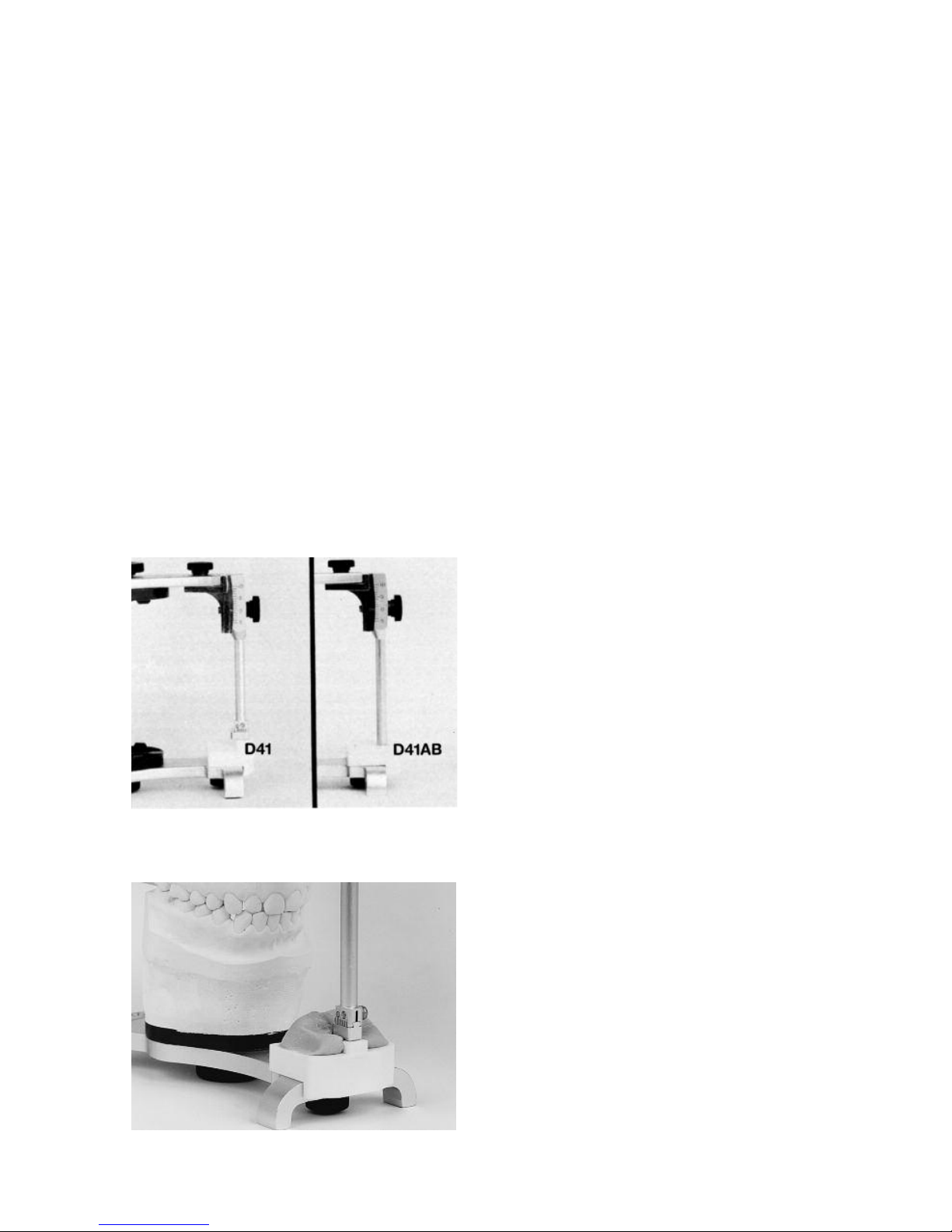
There are two different custom incisal
tables that fit Dénar®Articulators. They
are shown in fig 63. Part No. D41 is used
with articulators with the long centric
adjustment on the foot of the incisal pin.
Part No. D4 1 AB is used with articulators having the rounded foot on the
incisal pin.
To use either of the custom incisal
tables first attach a small mount of cold
cure acrylic to the posterior portion of
the incisal table. Part No. D41 has a
machined precision stop on its anterior
portion to maintain the correct vertical
dimension and care should be taken to
ensure that no acrylic is positioned on
the top of the stop. Also the long centric
adjustment at the foot of that incisal pin
should be turned so that the rounded
end will more efficiently mold the acrylic.
This is done by adjusting the foot so that
its anterior extremity is flush with the
anterior surface of its dovetail support.
When the acrylic has reached a rather
firm consistency, the articulator is
moved in right lateral, left lateral, and
protrusive excursions allowing the anterior teeth which are kept in contact to
guide these excursive movements
thereby functionally generating a custom incisal guide. This recording is
transferred to the incisal table and small
fleur-de-lis is generated in the cold cure
acrylic (fig. 64). This is later perfected
with a vulcanite burr.
The custom incisal table can be used to
best advantage in adjusting to the vertical and horizontal overlap relation of the
anterior teeth.This is particularly true in
adjusting the incisal guidance of the
articulator to natural teeth which exhibit
varying amounts of horizontal overlap of
the teeth which bear the horizontal load
in the protrusive, right lateral, and left
lateral excursive movements.
ADJUSTABLE INCISAL TABLE
Long Centric Adjustment.
The Long Centric Adjustment is located
on the foot of the incisal pin. When there
is a horizontal overlap of the anterior
teeth, or a “long centric”, the foot of the
incisal pin is adjusted to complement
this tooth relationship in the following
manner. Set the protrusive inclination of
the incisal table to its maximum angle.
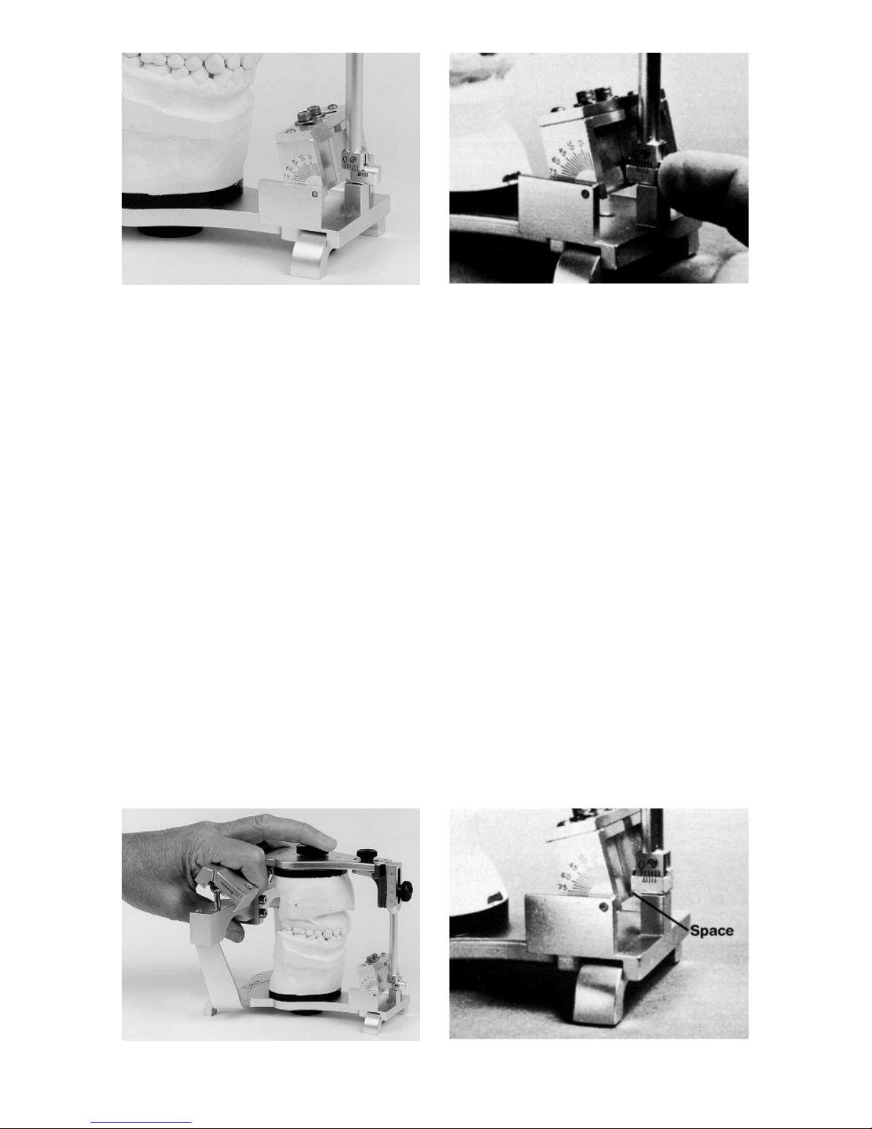
Loosen the foot of the incisal pin and
slide it forward (fig. 65). Move the upper
bow posteriorly until the lower anterior
teeth contact the lingual surface of the
upper anterior teeth (fig. 66).
VIII. INCISAL TABLE ADJUSTMENTS
fig. 64
fig. 63
Page 35
33
With the right index finger, push the foot
of the incisal pin back until it just contacts the inclined platform of the incisal
table, and tighten the incisal pin foot
lockscrew in that position (fig. 67). By
allowing the incisal pin to come forward
into the centric related position again, a
space will be noticeable between the
foot of the pin and the incisal table
__
this space is equal to the horizontal
overlap of the anterior teeth. (fig. 68).
Protrusive Adjustment
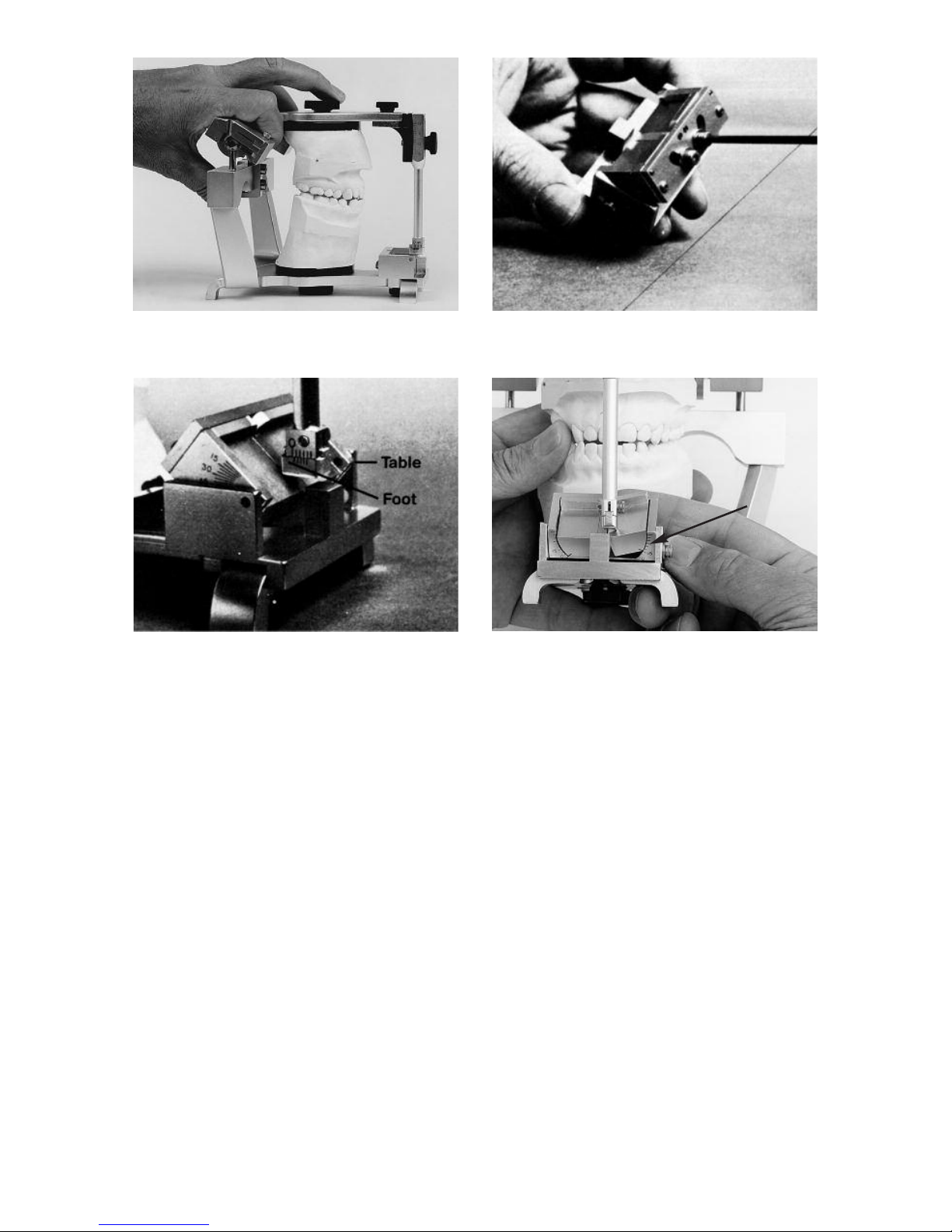
To adjust the incisal table for the inclination of the lingual bearing surfaces of
the anterior teeth, first loosen the incisal
platform and set it back to zero. Do not
tighten the lockscrew. Then, move the
upper bow posteriorly until the incisal
edges of the lower anterior teeth con-
tact the lingual surface of the upper
anterior teeth just lingual to their incisal
edges. Note that the incisal pin does not
touch the incisal table now (fig. 69).
Increase the angle of the table until it
touches the foot and lock the table in
that position (fig. 70).
Lateral Wing Adjustment
The lateral wings of the incisal table are
adjusted to complement the lateral relationships of the anterior teeth
__
most
frequently the vertical and horizontal
overlap relationships of the cuspid
teeth. To make this adjustment, first
remove the incisal table and loosen the
lateral wing lockscrews (fig. 71). Then
replace the incisal table on the articulator to observe visually the angle to which
the lateral wings must be adjusted to
fig. 67fig. 65
fig. 68fig. 66
Page 36
34
complement the anterior tooth relationships in the following manner. Hold the
articulator in a right lateral mandibular
position so that the right cuspids are in
function. (The upper bow is pushed to
the left. ) Note that the incisal pin does
not contact the incisal table. With the
right index finger, reach behind the tilting platform, and elevate the left wing of
the table until it touches the foot of the
incisal pin (fig. 72). Visually take a reading on the front scale to note its angular
setting. Do this same procedure on the
other side wing. Now remove the incisal
table from the articulator and tighten the
lockscrew wings at those settings. Then
attach the table to the articulator again.
fig. 69 fig. 71
fig. 70
fig. 72
Scale
Page 37

35
The rationale for utilizing the diagnostic
data obtained from protrusive and lateral checkbite records is as follows.
When the protrusive inclination of the
superior fossa wall is adjusted to the lateral checkbite record, a characteristic of
the orbiting condylar path is diagnosed.
This characteristic is associated with the
balancing inclines of posterior teeth on
the orbiting side__the mandibular buccal cusps’ lingual inclines’ mesial
aspects and the maxillary lingual cusps’
buccal inclines distal aspects.
When the protrusive inclination of the
superior fossa wall is adjusted to the
protrusive checkbite record, the inclination of the patient’s protrusive condylar
path is diagnosed. This inclination of the
superior fossa wall is associated with
the protrusive contacts of posterior
teeth__the mesial aspects of mandibular
cusps and the distal aspects of maxillary cusps.
The orbiting path inclination of the superior fossa wall adjusted to lateral checkbite records is always equal to or greater
than the protrusive path inclination of
the superior fossa wall adjusted to the
protrusive checkbite record.
FIXED RESTORATION AND
REMOVABLE PARTIAL DENTURE
RESTORATIONS
Adjusting the protrusive inclination of
the superior fossa to an angle which is
slightly less than the patient’s protrusive
condylar path (5 to 10 degrees less)
when the restoration is fabricated will
prevent the fabrication of protrusive
contacts, or balancing contacts on the
orbiting side of posterior teeth in the
laboratory. This is due to the fact that
when the restoration is seated in the
patient’s mouth and the patient’s
condyle tracks a steeper protrusive and
orbiting condylar path, the posterior
teeth will separate in both the protrusive
excursion and in the lateral excursion on
the orbiting side.
COMPLETE DENTURES
Method 1. Adjusting the articulator to
the patient’s protrusive condylar
path inclinations for both the protrusive and lateral excursive movements allows the fabrication of protrusive balance in the laboratory,
When the restoration is seated in
the patient’s mouth and the patient
executes a lateral mandibular
movement with the teeth in contact,
the patient will feel the primary
occluding pressures on the working
side. If the patient’s orbiting path is
slightly steeper than the articulator
setting when the restoration was
fabricated, the patient would perceive minimal occluding pressures
on the balancing side. However
orbiting side occlusal contact
would prevent loss of peripheral
seal.
Method 2. Adjusting the inclinations of
the superior fossa wall to the
patient’s orbiting path inclinations
allow the fabrication of bilateral balanced occlusion in lateral excursive
movements in the laboratory.
Subsequent adjustment of the
articulator to the patient’s protrusive condylar path inclinations permit adjustment of the occlusion to
protrusive balance. This method
permits development of full arch
balanced occlusion. (Note: Obtaining accurate eccentric checkbite records on extensive tissue
borne restorations, although theoretically attainable, is a difficult
accomplishment).
IX. TREATMENT PROCEDURES
Page 38

36
CHECKBITE PROCEDURE
The mandibular cast is transferred to
the articulator by:
1. occluding it with the maxillary cast
2. checkbite procedure
3. a combination of the above
In the transfer of the mandibular cast to
the articulator, if the mandibular cast
can be occluded accurately in the
desired most intercusped position, the
most accurate way to transfer the
mandibular cast to the articulator is by
occluding it with the maxillary cast.
However, if deflective contacts exist in
the patient’s mouth, they must either be
removed by grinding prior to the time
impressions are taken so the cast can
be accurately oriented in the desired
most intercusped position or the centric
relation record must be taken at an
increased vertical dimension by checkbite procedure.
There are many satisfactory recording
agents such as waxes, bite registration
pastes, etc., and many techniques with
which these agents can be employed to
advantage in checkbite registration procedures. However, there is no universal
method which proves optimum for all
situations. Therefore, the dentist must
be knowledgeable of the anatomy of the
related structures, neuromuscle physiology, mandible manipulation techniques
and in the physical properties of the
dental materials employed which determine checkbite accuracy. This will
enable him to effect a method of choice
as varying situations present themselves.
It is not within the scope of this text to
present an exhaustive discourse on
checkbite procedure. However, one recommended procedure which effects
basic principles of checkbite techniques
is presented. Variations of this technique
can be employed as circumstances dictate.
The following basic principles should
always be employed in any checkbite
technique.
1. The checkbite record should be
obtained as close to the vertical
dimension at which the restoration
is to be constructed as possible.
2. The dentist should always manipulate the patient’s mandible in
obtaining the checkbite. The
patient must not be instructed or
allowed to bite or close down in
such a manner as to cause flexion
of the mandible or movement of
teeth in obtaining the record.
3. The recording media interposed
between the teeth should be of a
dead soft consistency as the
mandible is brought to the desired
position. This prevents deflection
of the mandible and/or mobile
teeth, or the programming of muscle function.
TECHNIQUE FOR WORKING CASTS
The following technique can be used to
register the mandiblular position at the
correct vertical dimension or at an
increased vertical dimension. It can be
used to register centric or eccentric
position. Described will be the registration of the centric relation position of the
mandible at the minimal increase of vertical dimension which will result in lack
of posterior tooth contact.
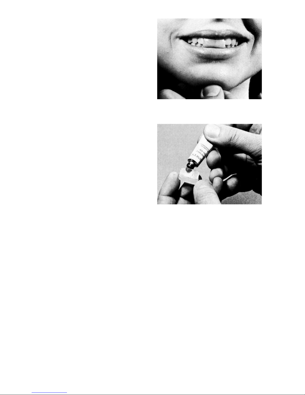
Fabricate an occlusal programmer by
softening a small piece of base plate
wax in a water bath to a soft consistency and adapt it over several teeth in the
anterior segment of the mouth as illustrated in fig. 73. Manipulate the mandible
APPENDIX A
Page 39
37
i
nto anterior centric relation and gently
guide the patient repeatingly in terminal
hinge closure to lightly tap the soft wax
to establish simultaneous contact of
several mandibular teeth on the wax.
The wax is removed from the mouth and
chilled in tap water. The number of
thicknesses of wax used should be the
minimum number to effect posterior disclusion.
A small amount of denture adhesive
cream is applied to the wax occlusal
programmer in the area that adapts to
the lingual surfaces of the maxillary
anterior teeth (fig. 74) The occlusal programmer is repositioned in the mouth by
reindexing it to the maxillary teeth. The
occlusal programmer thus establishes a
predetermined stop to vertical closure
with the condyles in centric relation.
There is an absence of contacting
deflective inclines posteriorly as a result
of group functioning of teeth in the anterior segment of the mouth where the
occluding pressures are the least. The
occlusal programmer reprograms muscle function so as to eliminate resistance
to terminal hinge closure previously programmed by deflective contacts.The
dentist can now more easily manipulate
the mandible in terminal hinge closure to
obtain the centric relation checkbite
record.
Similar occlusal programmers can be
fabricated in eccentric positions to facilitate obtaining of eccentric checkbite
records.
Suitable checkbite recording media
such as Bosworth’s Superbite ( a rapid
and hard setting zinc oxide and eugenol
base material) is placed on the
mandibular posterior teeth and the
mandible is guided in terminal hinge closure until the anterior teeth make light
contact with the occlusal programmer.
Since it is undesirable to register deep
fissures, grooves and undercuts on
teeth and cavity preparations with the
checkbite record media, these areas are
blocked out by wiping Vaseline or soft
wax over the teeth with the index finger
before the zinc oxide and eugenol paste
material is used for checkbite registration. The checkbite record media is
allowed to harden without the patient
executing a biting pressure. Figure 75
illustrates an occlusal programmer and
checkbite records accomplished with a
hard fast setting zinc oxide and eugenol
(ZOE) base material.
If the patient brings the mandible moving muscles into function during the setting of the record media, as may occur
during swallowing or bruxing, flexion of
the mandible or displacement of teeth
may occur which would result in an
inaccurate record. To insure that the
patient does not bring the muscles into
fig. 73
fig. 74
Page 40
38
function during the securing of the centric relation checkbite record, the dentist
should periodically gently arc the
mandible in small terminal hinge rotary
movements preceding the set of the
record media and immediately following
the set. Resistance to this movement
immediately prior to or after the set indicates functions of the patient’s mandible
moving muscles and the checkbite
record should be discarded and a new
one taken. If resistance to this movement is not encountered, the dentist can
be reasonable sure the patient did not
effect muscle function. This technique is
termed “dynamic technique” and the
record termed “dynamic checkbite”
because of the small movements of the
patients mandible executed by the dentist during the securing of the record.
The record media selected for this technique should allow an adequate, consis-
t
ent and not extended working time. It
should have a flash set to a hard consistence that will fracture without warping so the parts can be accurately
reassembled if fractured. The material
should be of a dead soft consistency
when mixed but it must also have sufficient body to resist flow so that it will
stay in place when positioned on the
teeth.
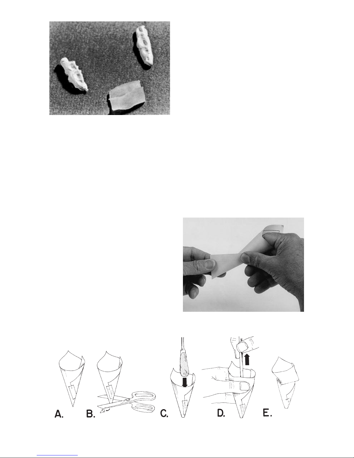
To facilitate the placement of the record
media on the occlusal surfaces of the
mandibular teeth construct small paper
cones from sheets of paper approximately 4 x 6 inches in dimension. Twist
the papter around the index finger as
illustrated in fig. 76 to fashion a cone
that has an opening at its large end
approximately 1-1/4 inches in diameter
(fig. 77A). The margin of the paper is
sealed with Scotch Tape so the paper
will not unwrap. The small end of the
fig. 75
fig. 76
fig. 77
Page 41
39
c
one is cut with a scissors to produce
an opening at the apex approximately
1/8 inch in diameter (fig. 77B).
Mix record media and gather it into one
mass on the end of the cement spatula.
Load the media into the bottom of a
paper cone (fig. 77C). Squeeze the
paper cone behind the record media to
capture the media near the apex of the
cone and to clean the spatula as it is
withdrawn (fig. 77D). After the spatula is
removed the cone is squeezed with the
index finger and thumb of both hands to
push all the media to the apex of the
cone and then the cone is folded back
on itself to prevent movement of the
media toward the large end of the cone
when it is compressed (fig. 77E).
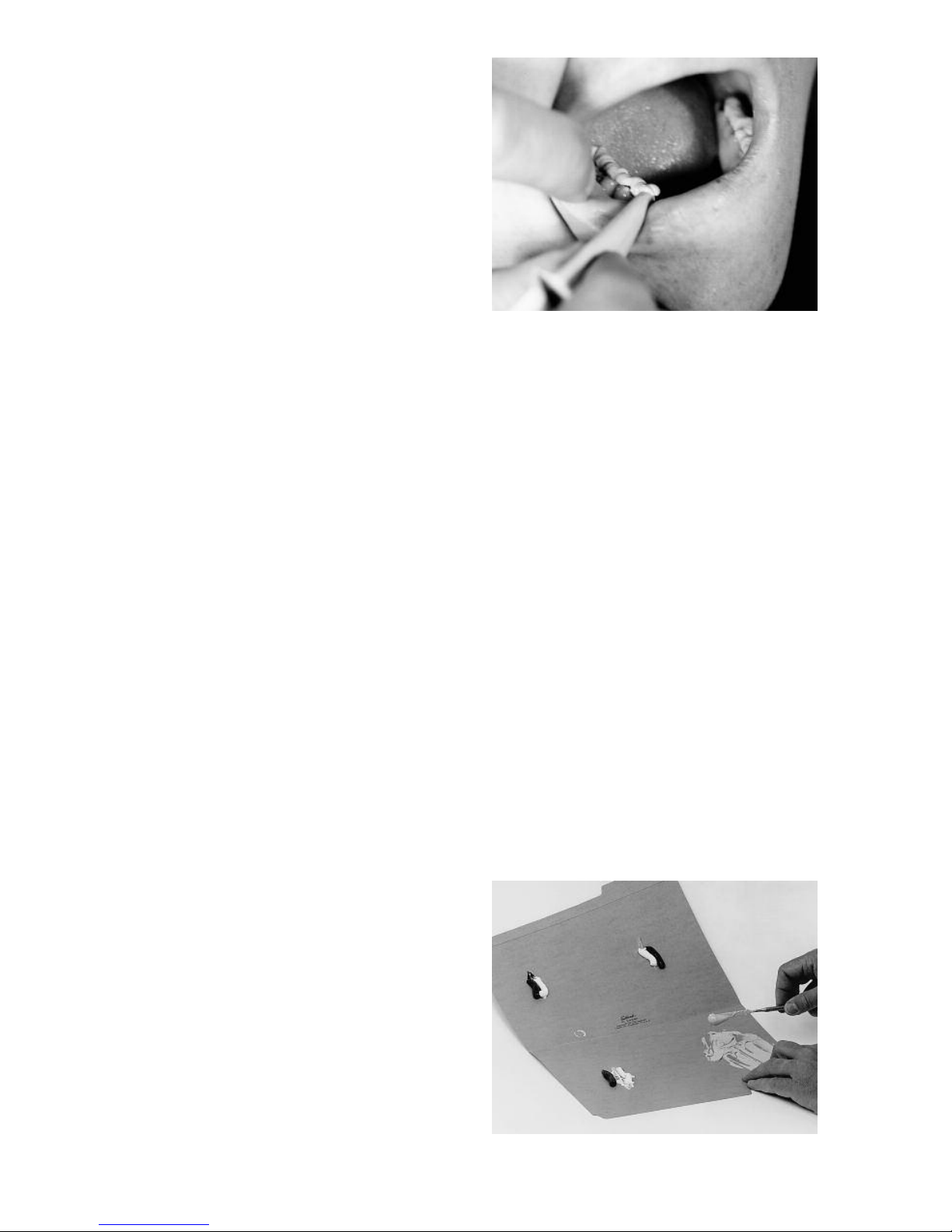
The cone is squeezed to dispense the
media into the central groove of the
mandibular teeth (fig. 78). As soon as a
cone is loaded the operator can proceed to apply the media to the teeth as
the assistant immediately begins to mix
another batch of material for securing
additional centric relation records.
An inexpensive file jacket is used as a
mixing pad and provides for convenient
disposal of the record media after use. It
is good procedure to obtain three centric relation records. One is used to
mount the mandibular cast and the
remaining two are used to double check
the mounting for accuracy with the
Denar
®
Vericheck technique presented
in Appendix B of this manual.
The setting times of zinc oxide eugenol
record medias vary with temperature,
humidity, spatulation time and batch
number. Under certain conditions the
material will set very rapidly and the
operator must work quickly to get the
material to place before the set occurs.
Alternately the material may set slowly.
Since it is difficult for the operator to
maintain the patient’s mandible in centric relation for extended periods of
t
ime,
time, the operator using a slow setting
record media should wait for a period of
time after the media is placed on the
mandibular teeth until the set is about to
occur before manipulating the patient’s
mandible to centric relation. Therefore,
the operator should dispense record
media for four batches of material on
the mixing pad (fig. 79). The first batch is
use to time the set of the media and is
discarded. The remaining three batches
are used to obtain the centric relation
records.
To time the set, mix the first batch of
material according to the manufacturers
recommendations. Load the cone and
apply the first batch of record media to
the mandibular teeth. Do not bring the
mandible to centric relation. The operator should then start to count slowly
until the set occurs. Once the set has
fig. 78
fig. 79
Page 42
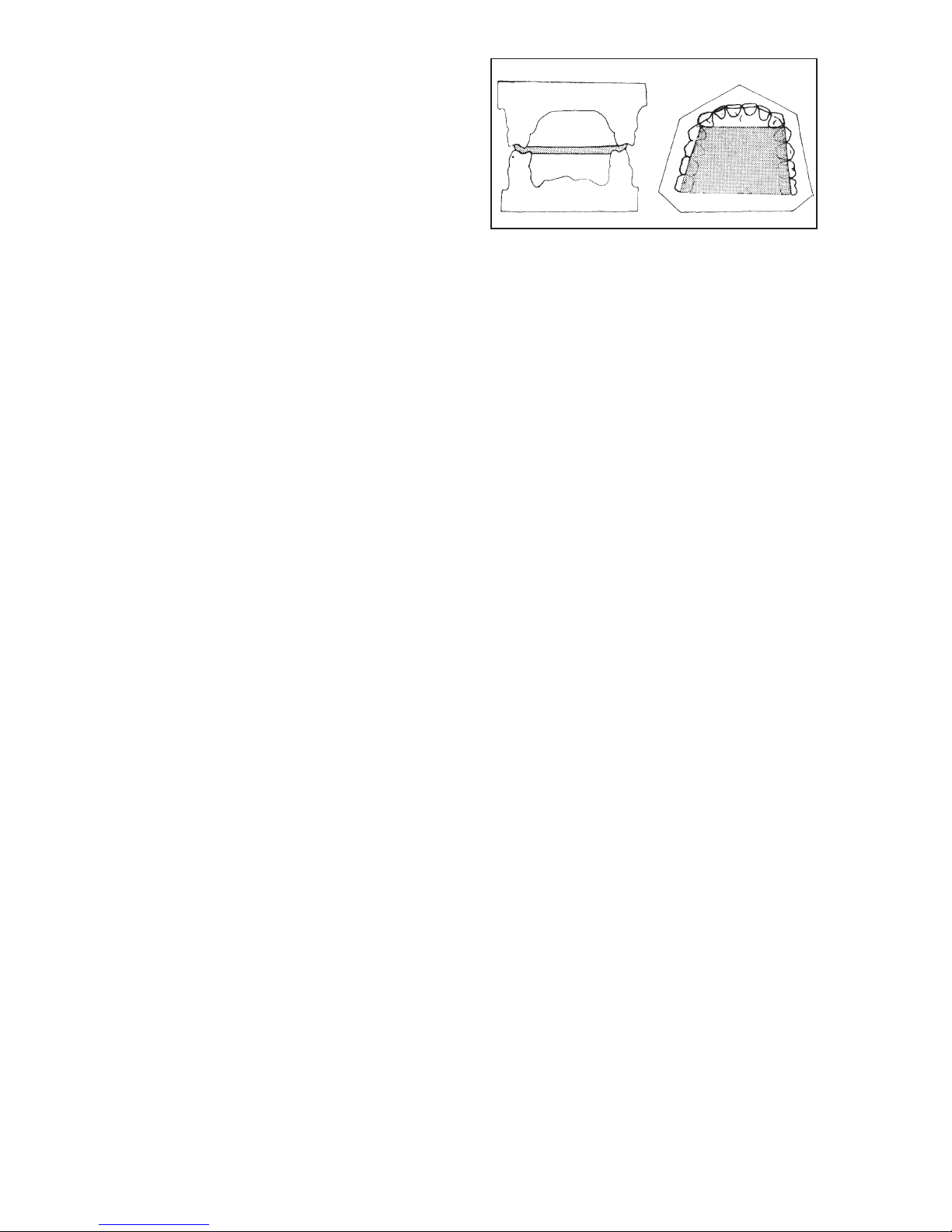
40
b
een timed the operator knows how
long to pause after the media has been
placed on the lower teeth before bringing the mandible to centric relation. It is
desirable to bring the mandible to centric relation just before the set occurs.
For best results it is important that the
operator and assistant work with consistent technique throughout this procedure.
TECHNIQUE FOR
DIAGNOSTIC CASTS
Checkbite records made of hard base
plate wax can be used to advantage
when mounting diagnostic casts. The
wax used should be of a hard, brittle
consistency and fracture without bending at room temperature. For obtaining
centric relation records develop wax
wafers composed of two thicknesses of
wax to the dimension illustrated in fig.
80. It is best not to include the anterior
teeth in the centric relation record if sufficient posterior teeth are present to stabilize the casts in the record.
To develop the wax wafers soften a
sheet of base plate wax in a water bath
or open flame. Flame one surface of the
wax and fold the wax over on itself on
the flamed surface to bond the wax into
a wafer consisting of two thicknesses of
wax. With a warm spatula trim the wax
slightly oversize of the desired dimension. With the wax slightly softened so
the wafer is pliable, position the wafer
on the maxillary teeth and using the
index fingers adapt the wax to the teeth
to obtain very light indexing impressions
of the cusps tips and to contour the
wafer to the plane of occlusion. Do not
impress the mandibular teeth into the
wax at this time. Chill the wax with air so
that it will maintain the shape of the
plane of occlusion and remove the wafer
from the mouth. With a warm scalpel
trim the wafer to the desired dimensions.
Check the wafer in the mouth or on a
maxillary cast to confirm that the wafer is
contoured to the plane of occlusion and
is stable on the maxillary teeth.
Soften the lateral edges of the wax in an
open flame until it is dead soft. Quickly
temper the wax in a water bath and
position the wafer on the dry maxillary
teeth to obtain light impressions of the
tips of the cusps as previously
described. Guide the mandible in centric relation closure to obtain light
impressions of the mandibular cusp tips
in the record. It is important that the
operator guides the mandible to the
desired position.The patient should not
be instructed to bite down or close. As
soon as the impressions are obtained,
chill the wax with air and remove it from
the mouth. The record is chilled in cool
water and returned to the mouth and
checked for accuracy. The wafer is
placed on the maxillary teeth and the
mandible is arced in centric relation closure to occlusal contact. The mandibular cusp tips should come into simultaneous even contact with their impressions in the record. When the mandibular teeth are brought into extemely light
occlusal contact with the record the
patient should preceive no premature
contact or uneven pressure on questioning.
Lateral Checkbite Records
A technique for fabricating a right lateral
checkbite record is described. The left
lateral record is obtained in a similar
manner.
Train the patient to allow you to arc the
mandible in hinge retation with the
patient’s rotating condyle in its most
fig. 80
F
igure 80 courtesy
Dr. P. Dawson and C.V. Mosby Co.
Page 43
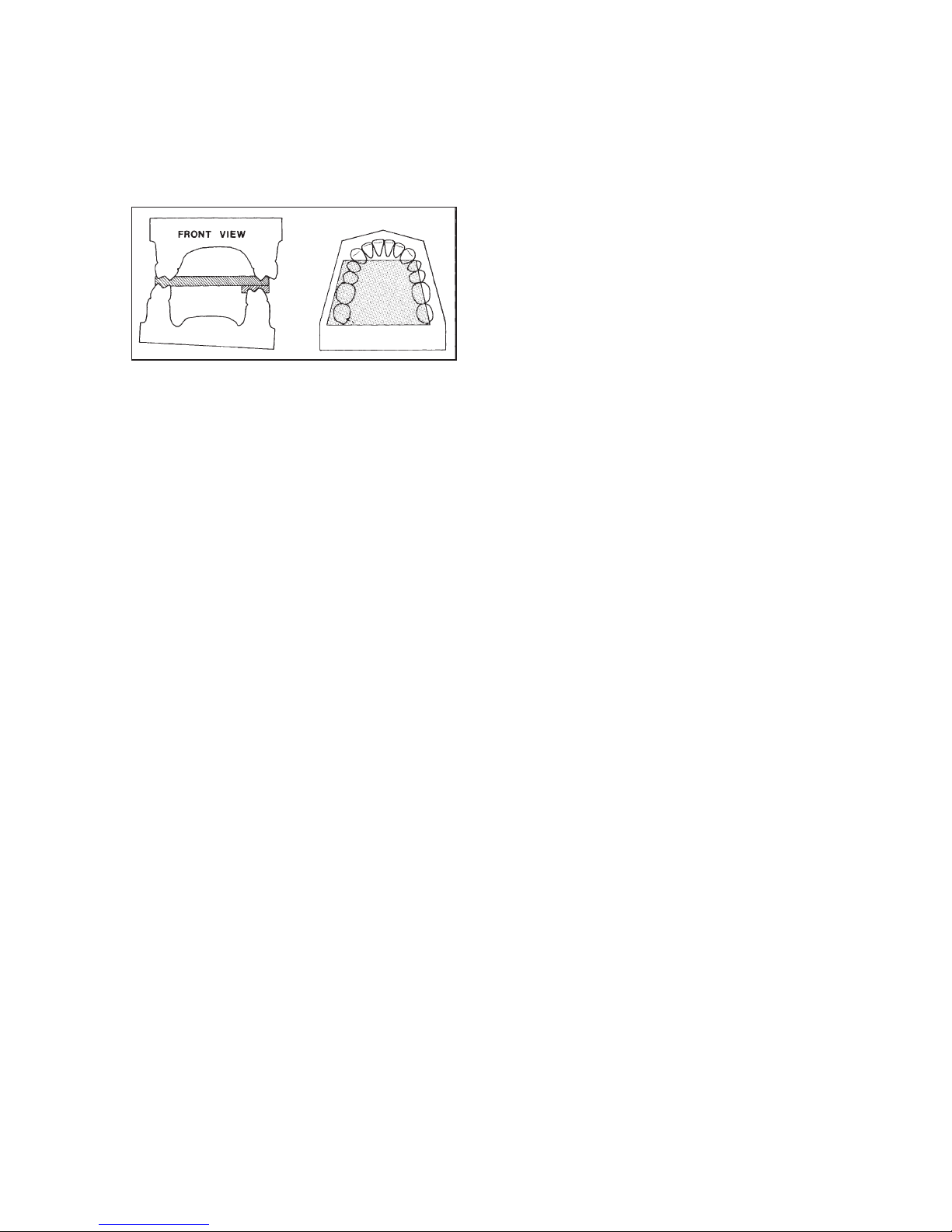
41
retruded position and the orbiting
condyle advanced approximately seven
millimeter. This can be done with the
“thumb on chin” method with the thumb
on the anterio-inferior border of the
mandible in the area of the left cuspid.
Construct a wax wafer composed of
two thicknesses of hard base plate wax
to the dimensions illustrated in fig. 81.
This is done by fabricating an oversized
wafer as previously described and
adapting it to the maxillary teeth with the
index fingers to conform the wafer to the
plane of occlusion and to obtain light
imprints of the cusp tips. Chill the wafer
with air and remove it from the mouth.
Use a warm scalpel to trim the wafer to
the desired dimensions. Return the
wafer to the mouth, and position it on
the maxillary teeth to confirm that it is
stable on the maxillary teeth and conforms to the plane of occlusion. Guide
the mandible in right lateral closure to
contact the wax and determine the
number of additional strips of wax which
must be added to the lateral extremities
of the mandibular side of the wafer to
establish even contact with the
mandibular teeth. Lute additional thicknesses of wax to the mandibular side
and then heat the lateral extremities of
the wafer in an open flame to soften the
wax. Quickly temper the wax in a wafer
bath and position the wafer on the dry
maxillary teeth. Guide the mandible in
right lateral closure to obtain light
imprints of the cusp tips in the wax. Chill
the wax with air and remove the wafer
from the mouth and place it in cool
water. The wafer can be returned to the
mouth and checked for accuracy.
fig. 81
Page 44

42
The following protocol was developed
by a panel of experts in occlusal treatment on the philosophy that a dentist
seeking good laboratory support will
give the technician complete specifications for fabrication of the occlusal
aspects of the restoration.
Recognizing that the position of maximum intercuspation is of paramount
importance, it is the responsibility of the
dentist who takes the centric relation or
centric occlusion interocclusal record to
mount the mandibular cast. Complete
specifications furnished by the dentist
to his laboratory for fabrication of the
occlusal aspects of restorations include:
1. Full arch master casts mounted in
an instrument with trimmed dies or
dies with margins that are easily
identifiable.
2. Instructions for adjusting articulator condylar controls (if adjustable)
when the restoration is fabricated
plus records for adjustment of the
incisal table.
3. Specifications as to which teeth
are to bear the load in eccentric
bruxing movements.
4. Specifications for the class of
occlusal anatomy desired and the
character of the position of maximum intercuspation as described
below.
DISCUSSION
Mounted Casts with Trimmed Dies
To specify that it is the responsibility of
the dentist to mount the mandibular
cast does not mean that he cannot delegate this procedure to a dental auxiliary. For example, in limited restorative
procedures in which there are sufficient
unprepared teeth to accurately index full
arch casts in the position of maximum
intercuspation, the mounting procedure
could certainly be delegated to a dental
auxiliary. However, as the restoration
becomes more extensive, if the dentist
delegates the mounting of the casts to a
dental auxiliary and an error is introduced, the dentist should still assume
full responsibility for the mounting error.
Instructions for Adjustment of
Condylar Controls
To specify that the dentist should provide instructions for adjusting condylar
controls does not mean that the restoration is to be constructed on a fully
adjustable articulator. An example of
instructions for adjustment of the
condylar controls could be: “Lock the
instrument in centric relation throughout
the laboratory procedure”. It is the
responsibility of the dentist to specify to
his technician if he wants consideration
given to eccentric factors of occlusion
in the laboratory, and if so, to what
extent.
Dentist__Laboratory Relations
Currently, most dentists send unmounted casts to the laboratory for fabrication
of prosthetic restorations. Restorations
are returned to the dentist on unmounted casts. If the occlusion is found to be
in error when the restoration is inserted
in the patient’s mouth, who made the
error__dentist or technician? This condition can result in strained dentist-laboratory relations.
It is the responsibility of the dentist who
takes the centric relation record to
mount the mandibular cast. When the
restoration is returned to the dentist on
full arch mounted casts the dentist has a
basis for accurate communication with
his laboratory. If the laboratory services
APPENDIX B
DÉNAR SYSTEM PROTOCOL FOR DENTIST-LABORATORY RELATIONS
Page 45
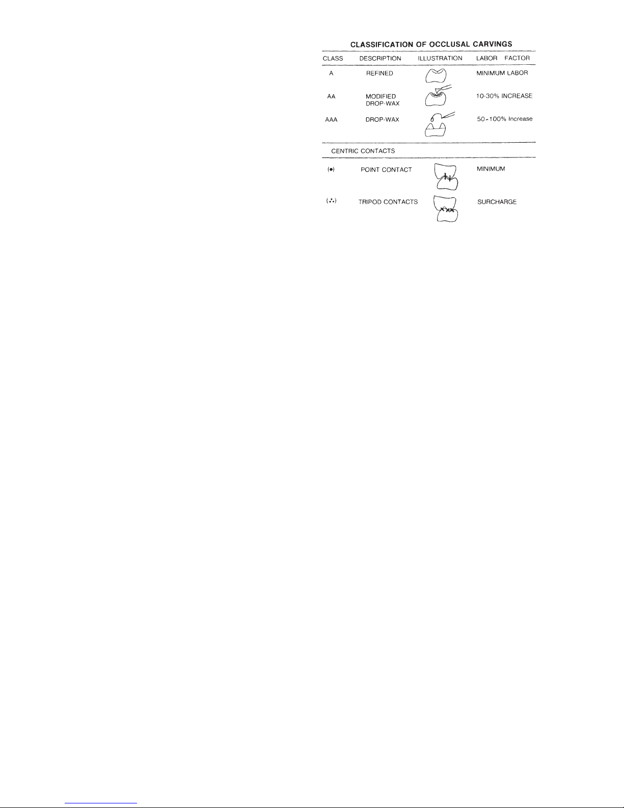
43
a
re found to be satisfactory and
occlusal discrepancies are identified in
the mouth, the dentist is confident that
the error was not introduced in the laboratory. He can then re-evaluate his procedure to determine the source of error.
In other words, if the restoration fits the
mounted casts but not the mouth, the
technician cannot be expected to participate in the additional cost of remakes
not attributed to laboratory procedures.
CLASSIFICATIONS OF OCCLUSAL
CARVINGS
The following classification of occlusal
carvings as illustrated in figure 82
enables the dentist to specify to the laboratory the relative amount of time and
effort he desires the laboratory to
expend (and consequently the laboratory fee) to fabricate the prescribed occlusion.
Alloy Restorations
Class A__Refined Occlusal Carving
The restoration is fabricated in the manner the technician might employ when
using a simple crown and bridge hinge
mechanism. When the occlusion is
semi-developed, the technician simply
bruxes the instrument to burnish away
eccentric interferences and refines the
anatomy of the remaining wax.
Eccentric irritations are removed from
the occlusion in the laboratory. This is
the application of principles of occlusion
in its simplest form and consequently is
a minimum fee laboratory service.
Class AA__Modified Drop Wax
Basically, this is a Class A carving with
more refinement. The technician carves
in supplemental grooves and then
accentuates triangular, cuspal and marginal ridges with the drop wax technique. The ultimate appearance will be
similar to a Class AAA carving. A Class
AA carving requires more laboratory
time than a Class A carving and so the
laboratory fee should reflect 10% to
30% increase in the labor factor of the
Class A carving.
Class AAA__Complete Drop Wax
The drop wax technique is employed to
restore the total occlusal surface and all
restored axial surfaces to obtain the
maximum esthetic cusp height, optimum cusp distribution, and to harmonize the occlusal anatomy with condylar
paths of movement. This type of
occlusal fabrication requires more time
and skill than a Class A or Class AA
carving and consequently the laboratory
fee reflects a 50% to 100% increase in
the labor factor of a Class A carving.
However, this can only be done on a
restoration involving extensive tooth
reduction. For example, if the restorations are MOD inlays or onlays with minimum tooth reduction, the cusp distribution has already been accomplished and
the laboratory only needs to do the fillin-procedures of the drop wax technique. Consequently, a Class AA or AA+
carving would suffice.
Centric Contacts
The character of the centric contacts
must produce axial loading of the teeth.
This can be accomplished by:
1. Point Contact (•). There is an
absence of contacting inclines.
fig. 82
Page 46

44
C
entric stops are on high spots or
low spots of cusps.
2. Tripod Contacts (...). Centric cusps
do not hit on their tips but are supported by three or sometimes only
two centric contacts on the
perimeter of cusp tips.
Developing tripodized centric contacts
(...) requires more laboratory time than
point contacts (•). Consequently, an
additional laboratory fee is required.
When the dentist’s prescription specifies a Class AA (...) occlusion, it means
he desires a Class AA carving with
tripodized centric stops and he anticipates a laboratory fee which will allow
the technician adequate time to perform
this service.
PORCELAIN RESTORATIONS
An extension of the above classification
for alloy restorations is used for specifications of porcelain restorations.
Class A porcelain restorations are
carved to look like Class A alloy restorations. Class AA porcelain restorations
are carved with more detail to accentuate supplemental grooves and cusp
height to look like a Class AA or AAA
alloy restoration. A plus symbol (+)
denotes additional staining and characterization.Thus a Class AA (•)+ porcelain
restoration is carved to be similar to a
Class AA alloy, has point contact centric
stops with an absence of contacting
inclines and has special staining characterization.
DISCUSSION
Laboratory Fees and Instruments for
Occlusal Treatment
The laboratory fee is for the time and
skill which the technician employs in
harmonizing the occlusion to condylar
paths of movement and is not determined by the instrument used. A fully
adjustable or semi-adjustable articulator
can be bruxed as easily as a simple
crown and bridge hinge mechanism that
has springs for condylar posts.
The above classification of occlusal
carvings is not an attempt to establish
laboratory fees. It is offered as a means
of establishing more accurate communications between dentist and laboratory.
SUMMARY
The protocol which requires the dentist
to mount the mandibular cast gives the
dentist “laboratory-control”. This control
of services usually results in better laboratory work. The laboratory on the other
hand receives “dentist control” and less
reduced fee remake discussions.
The dentist who mounts his mandibular
cast and provides the technician with
complete specifications for fabrication
of the occlusal aspects of the restoration enjoys the benefits of improved
communications with his laboratory,
laboratory control, better laboratory
work, and improved dentist__laboratory relations.
Page 47
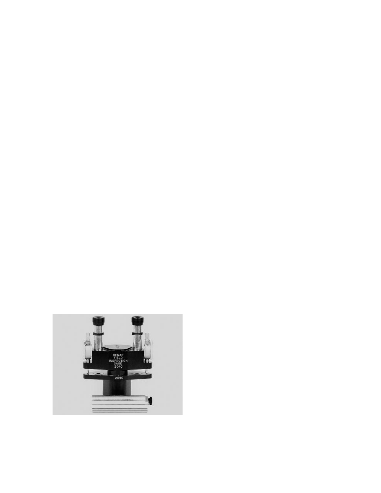
45
The Dénar®Field Inspection Gage is an
optical inspection gage used to calibrate Dénar
®
Articulators and laboratory
Relators to tolerances which allow the
transfer of mounted casts between calibrated articulators and Lab Relators.
NOTE: This manual details the use of
the Dénar
®
Field Inspection Gage to cal-
ibrate the Dénar
®
Mark II Semiadjustable Articulator. It does not detail
the calibration procedure for the Dénar
®
D5A Fully Adjustable Articulator and D6
Centric Lab Relator; nor does it describe
the recommended applications of the
Dénar
®
Two-Instrument System. For
complete information on these subjects
the reader is referred to the Dénar
®
Office Tutor (Cat. #D1269) and the
Dénar
®
Field Inspection Gage
Instruction Manual (Cat. #D166).
The gage consists of an upper member
called the “scope” and a lower member
called the “stage.” The gage is supplied
with two inter-bow gage pins. Inter-Bow
Gage Pin #1 and Inter-Bow Gage Pin #2
(fig. 83).
CARE OF DÉNAR
®
FIELD
INSPECTION GAGE
The Dénar
®
Field Inspection Gage is a
precision instrument capable of making
measurements in three directions to an
accuracy of one ten thousandths of an
inch (.0001”). To insure its continued
accuracy, the components should be
handled carefully and not be allowed to
come to rest on a hard surface with a
force which would cause a nick or
deformation of the bearing surface.
When a component is not in use, it
should be kept in its protective case. It
is advisable to have a piece of cork, rubber, cardboard or other soft, lint-free
surface to rest the gage components on
when they are not mounted in their case
or on a Dénar
®
instrument.
IMPORTANT There are several socket
set screws on the scope member of the
Field Inspection Gage. Do not attempt
to turn these screws with a wrench.
These screws are for use of factory
authorized personnel only. Manipulation
of these screws can affect the accuracy
of the instrument.
For accuracy, it is important that the
bearing surfaces of the Field Inspection
Gage components, Articulator, Lab
Relator, as well as the mounting plates,
be wiped clean of foreign material prior
to their use.
VERTICAL ALIGNMENT
Prior to using the Field Inspection Gage
to align a Dénar
®
Articulator or Lab
Relator the distance between the maxillary and mandibular bows (inter-bow
distance) of the articulator or Lab
Relator must be precisely established
by means of the inter-bow gage pin #1,
as illustrated in fig. 84.
APPENDIX C
CALIBRATION PROCEDURE
fig. 83
Page 48
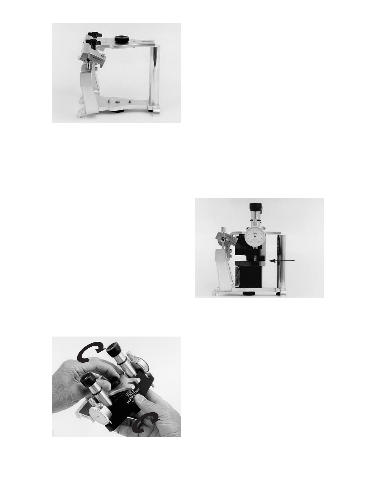
46
To use this pin the adjustable incisal pin
and the incisal table are removed and
the inter-bow gage pin #1 is secured in
position as shown.
Carefully and without forcing, mount the
gage components flush to the articulator bows. Make sure to turn the gage
component relative to the articulator
bow in the same direction to which the
lockscrew is turned as the gage is
secured to the bow of the articulator (fig.
85).
It is important that the operator use a
consistent amount of torque when tightening lockscrews to secure mounting
plates or a Field Inspection Gage to the
bows of an articulator or Lab Relator.
Tighten the lockscrew without forcing.
W
hen placing a gage component onto
the bow of an articulator the index holes
on the surface of the gage that faces the
articulator bow should be carefully and
visually located over their respective
index pin on the bow of the articulator to
prevent damage of the bearing surface
of the gage. DO NOT SLIDE THE GAGE
laterally over the index pins in an
attempt to locate the index pins in the
gage by feel. This can cause damage if
done with too much force.
Figure 86 illustrates the Field Inspection
Gage and inter-bow gage pin 1 mounted in the articulator. At this time you will
note that a space of approximately 1/4
to 1/2 millimeter exists between the
scope and the stage.
Optional: If you wish to confirm that your
gage is accurate proceed in the following manner. On the back of the stage
you will find a calibration record as illustrated in fig. 87. The two large circles
represent the faces of the dial indicators
on the right and left sides of the gage as
viewed from the rear. On each circle is a
scribed calibration mark which is usually found between the +10 and +20 graduations. Each graduation represents one
half-thousandth of an inch (.0005”).
These readings are the values which the
dial indicators on the respective sides of
the instruments should read when the
scope is allowed to rest on the stage
fig. 84
fig. 85
fig. 86
Space
Page 49
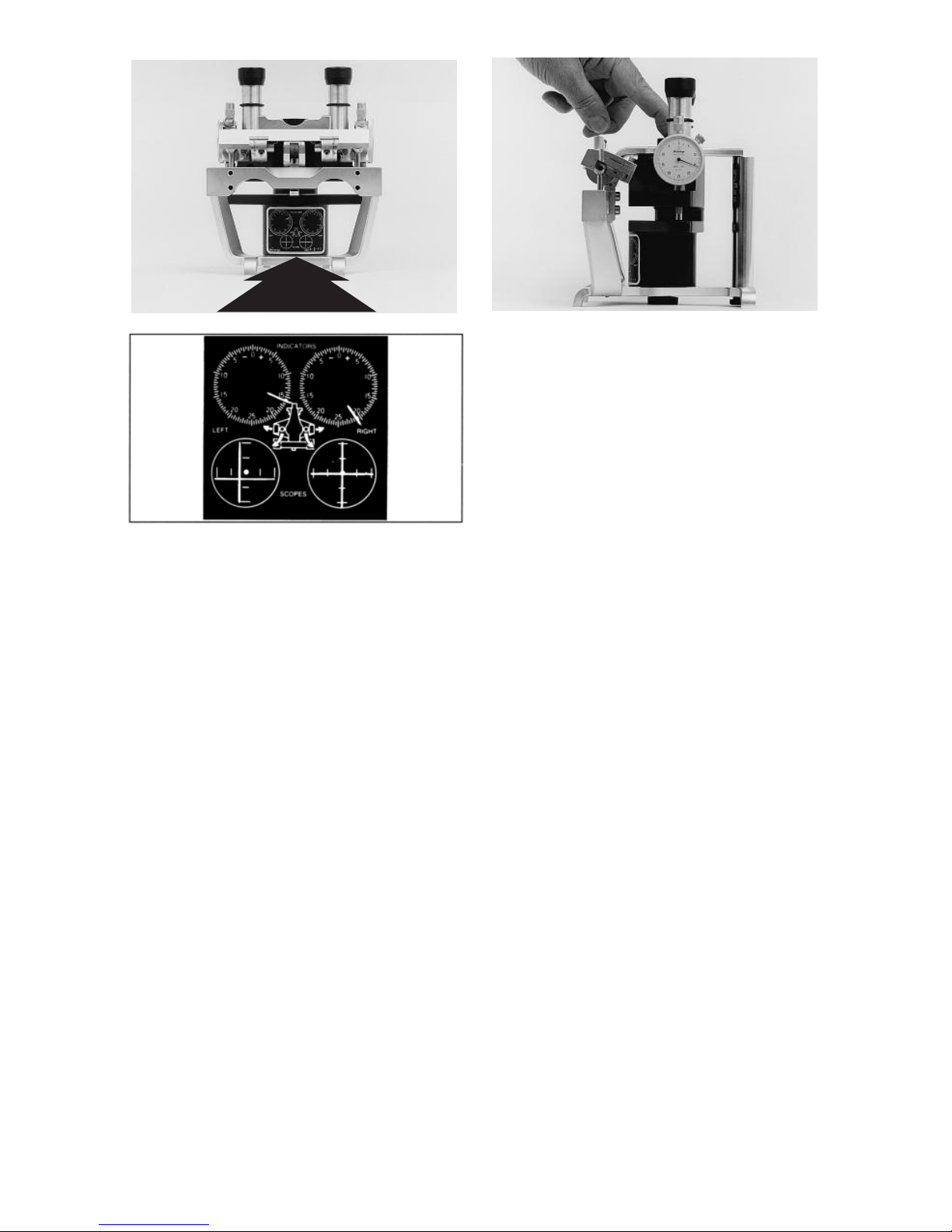
47
by loosening the maxillary lockscrew
while the Field Inspection Gage is
mounted in an articulator or Lab Relator.
To confirm that your field gage is accurate, simply loosen the maxillary
lockscrew which secures the scope to
the maxillary bow and firmly press on
the lockscrew as illustrated in fig. 88 to
insure that the scope rests on the stage.
If the dial indicators do not register the
calibration values scribed on the calibration record on back of the stage,
simply loosen the lockscrew on the face
of the dial indicator (fig. 88) and rotate
the face of the indicator until the indicator reads the desired value and then
lock the face in position. The field gage
is now calibrated. Resecure the scope
to the face of the maxillary bow, remembering to make sure that you rotate the
face of the indicator until the indicator
reads the desired value and then lock
the face in position. The field gage is
now calibrated. Resecure the scope to
the face of the maxillary bow, remembering to make sure that you rotate the
scope in the same direction that you
turn the lockscrew as you secure the
scope to the face of the articulator. At
this time the dial indicators will register
“O” if both condylar elements of the
articulator are at the correct height.
If the height of the condylar elements
are out of specification proceed in the
following manner. On the posterior
aspects of the horizontal crossbar are
vertical adjustments (A) and vertical
adjustment lockscrews (B) as illustrated
in fig. 89. Loosen the vertical adjustment
lockscrews on both sides of the articulator. While applying downward pressure on the maxillary bow above the
condyles, manipulate both vertical
adjustments until both dial indicators
read +5 to +10. A plus reading indicates
that the condyles are below the desired
height. Note that when you change the
height of one condyle it affects the reading on both dial indicators. Snug the
vertical adjustment lockscrews to firmly
seat the pins supporting the condylar
elements in their housings but do not
tighten all the way. At this time both
condylar elements are just below the
desired height. Alternately tighten the
vertical adjustment screws in small
increments on the right and left sides of
the instrument until both dial indicators
read “O”. Tighten the vertical
fig. 87
fig. 88
Page 50
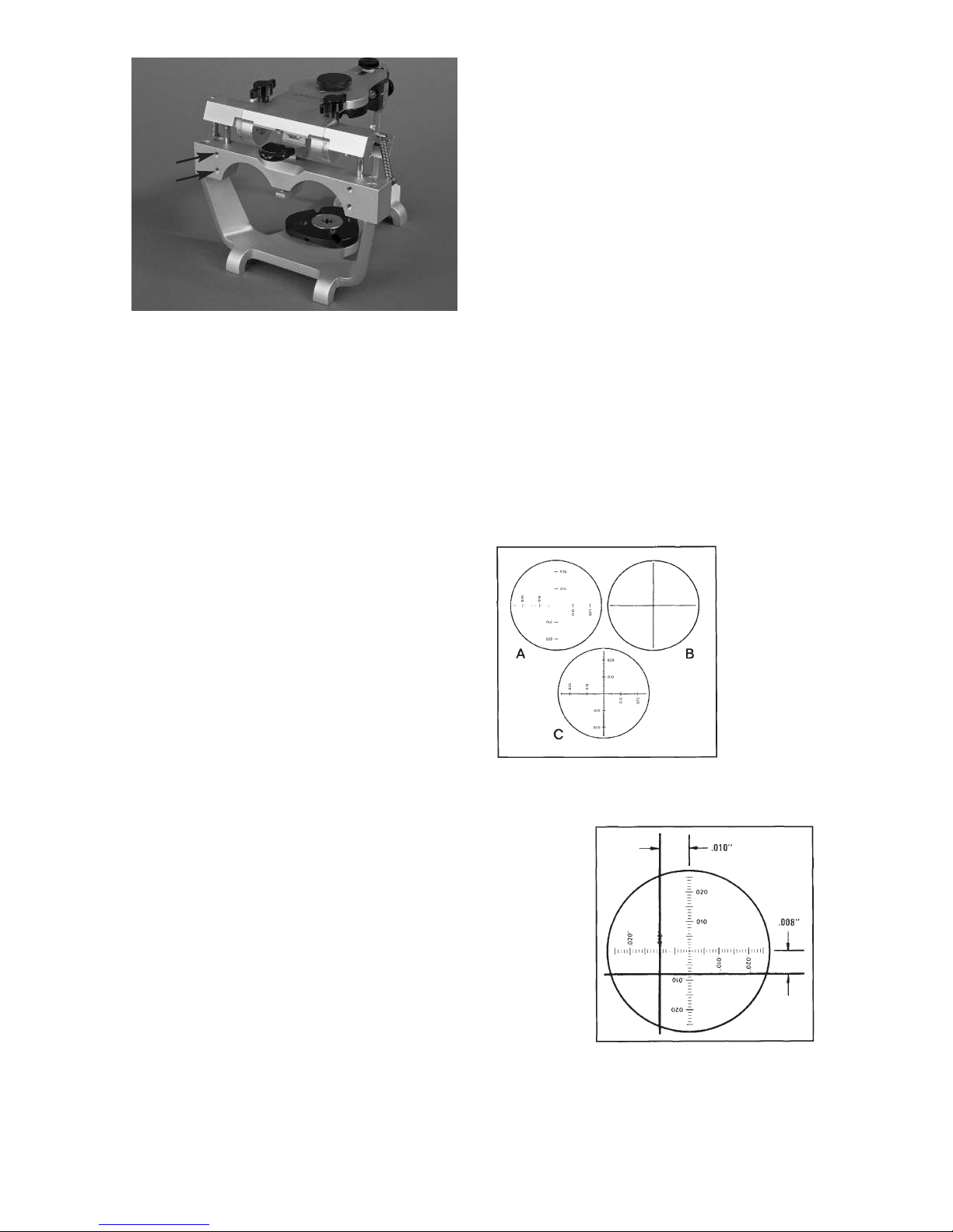
48
adjustment lockscrews to secure the
condylar elements in this position.
HORIZONTAL ALIGNMENT
The articulator must be in specification
in the vertical dimension before horizontal alignment is made.
On the scope member of the Field
Inspection Gage are two forty power
(40x) monocular scopes. You are to look
through these scopes one at a time. In
each scope is a reticle graduate in one
thousandths of an inch (.001”) increments in four directions off of a centric
dot as illustrated in figure 90A. On the
lateral wings of the stage are crosshair
targets as illustrated in figure 90B. If an
articulator is in perfect specification
anterior-posteriorly and medio-laterally,
the intersection of the target crosshairs
will touch the centric dot of the reticle as
in figure 90C when viewed through the
scope. If the articulator is out of specification as illustrated in figure 91, the
amount it is out of specification can be
measured with the graduated reticle. For
example, figure 91 illustrates the view
through the scope of an articulator out
of specification ten thousandths of an
inch (.010”) medio-laterally and eight
thousandths of an inch (.008”) anterioposteriorly.
To align an articulator in the horizontal
plane, proceed in the following manner.
O
n the back of the stage is a calibration
record as illustrated in figure 87. The
two small circles on the lower portion of
the record are the calibration records for
the scope’s on the respective sides of
the articulator. Each graduation off of
the centric dot represents one thousandths of an inch (.001”). the total
diameter of each small circle represents
a little over four thousandths of an inch
(.004”), or about the thickness of normal
writing paper. In each of the small circles
you find a scribed cross mark. This mark
represents the true centric position. In
other words, when you look through the
monocular scopes, the true centric
position in some gages is that position
indicated by the scribed cross marked
on the calibration record.
fig. 89
fig. 90
fig. 91
A
B
Page 51
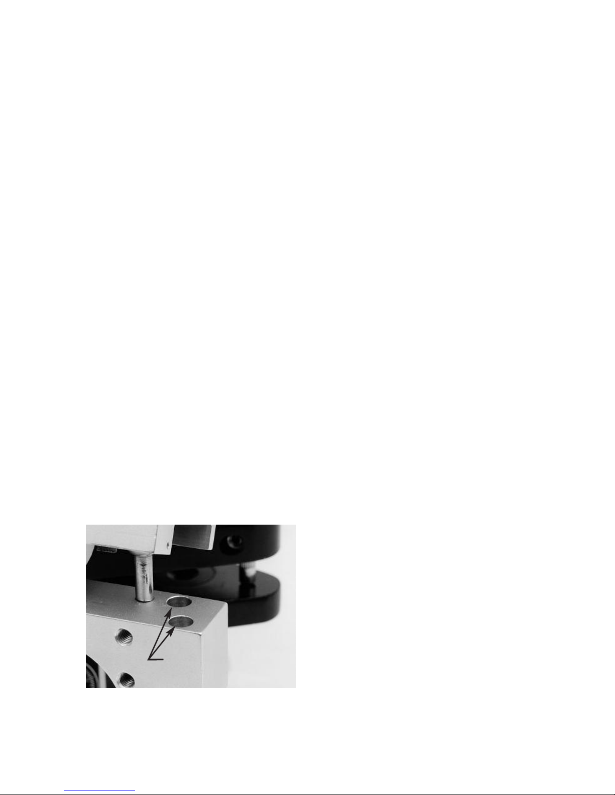
49
T
his calibration system is used because
in manufacture, slight creepage of the
centric dot of the reticle can occur. This
calibration system allows for corrections
of this error and maximum accuracy.
In the following instructions to adjust the
horizontal alignment of the articulator, it
is assumed that the scribed crosses
marked on the calibration record coincides with the centric dots of the reticle.
Loosen the horizontal adjustment
lockscrews illustrated in figure 92 on
both sides of the articulator the minimum amount necessary to allow horizontal crossbar. Engage the centric
latch of the articulator. While maintaining slight downward pressure on the
horizontal crossbar of the lower member
of the articulator to keep the horizontal
crossbar seated flush on the crossbar
supports, slide the horizontal crossbar
and maxillary bow assembly in the horizontal plane until the centric dots are on
the junction of the crossbar targets as
viewed through both scopes. Then while
carefully maintaining this crossbar position incrementally tighten in a crisscross
sequence the four horizontal adjustment
lockscrews.
The articulator in now calibrated in the
centric position.
RUN-OUT INSPECTION
PROCEDURE
The articulator was aligned by means of
the Field Inspection Gage with the protrusive condylar path inclinations set to
30 degrees. Readjust the right protrusive condylar path to 10 degrees and
tighten the lockscrew. Record the reading on the right dial indicator. The two
readings indicate the amount of run-out
of the articulator adjustment. Factory
specifications require that all articulators
have a run-out of less than plus or
minus five thousandths of an inch
(+.005”).
REINSERTION OF THE
ADJUSTABLE INCISAL PIN
After an articulator is properly aligned by
means of a Field Inspection Gage, the
most convenient way to set the
adjustable incisal pin to an accurate
zero position is to remove the incisal pin
#1 and reinsert the incisal table and
adjustable incisal pin set to zero. If the
dial indicators do not read zero the
height of the adjustable incisal pin can
be minutely adjusted until the dial indicators read zero.
INTER-BOW GAGE PIN #2
Inter-bow gage pin #2 is used to precisely adjust incisal pins to the zero
dimension in articulators and Lab
Relators known to be in specification.
The incisal pin is raised and the interbow distance is established by means
of the inter-bow gage pin #2, as illustrated in figure 93.
The adjustable incisal pin is then adjusted and secured to maintain the interbow distance established by the interbow gage pin #2. It is important to apply
downward pressure on the top of the
adjustable incisal pin as the lockscrew is
tightened to prevent upward creepage
of the incisal pin when tightening the
lockscrews as illustrated in figure 94.
fig. 92
Horizontal
Adjustment Screws
Page 52
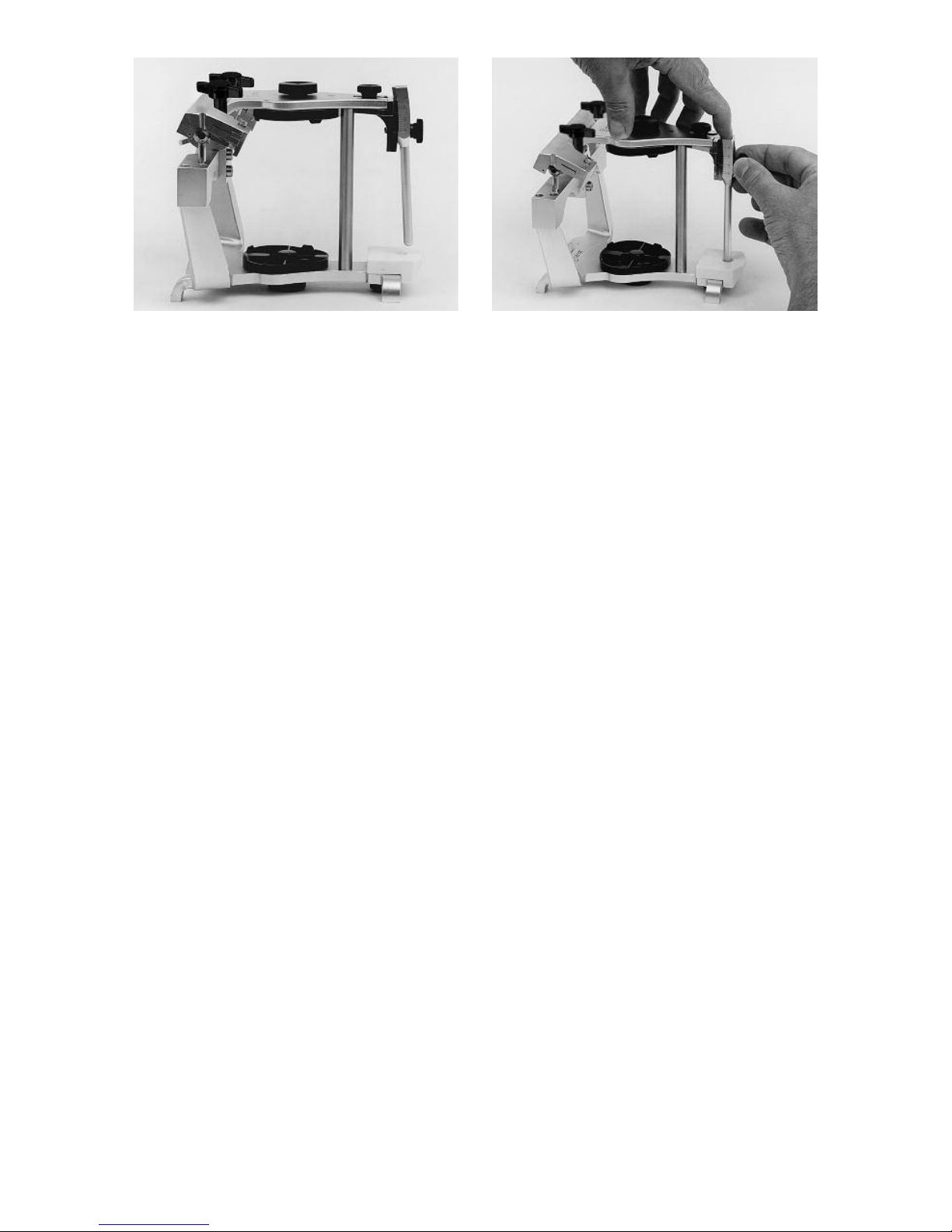
50
Use of the inter-bow gage pin #2 requires
a little care and skill. Therefore, after this
adjustment is made be sure to check
carefully to confirm that the inter-bow
dimension of the gage pin was in fact
transferred to the adjustable incisal pin.
fig. 93 fig. 94
Page 53
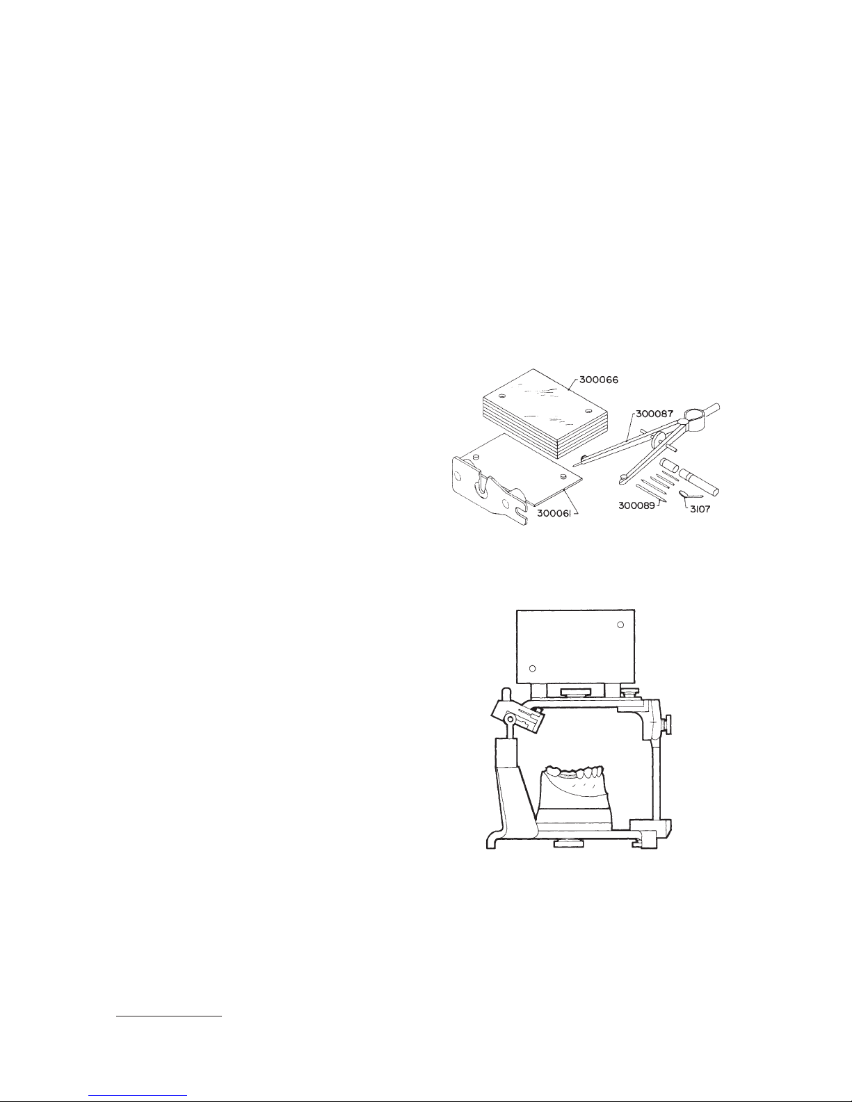
51
The Broadrick Occlusal Plane Analyzer
is used for analyzing the Curve of Spee
and developing an acceptable curve of
occlusion, and is recommended for laboratory procedures employing the
Functionally Generated Path Technique.
Note: This text describes the
mechanical function of the Broadrick
Occlusal Plane Analyzer. The reader
is urged to refer to other textual
material as well as classes devoted
to the clinical application of this procedure in occlusal correction.
A Broadrick Occlusal Plane Analyzer, fig.
95, consists of (1) Card Index #300061,
(1) Bow Compass #300087 with
graphite leads of varying hardness,
1
(1)
extra center points #300088, (`1)
Scribing Knife #3017, (1) Needle Point
#300089, and (2) Plastic Record Cards
#300066.
To use the Occlusal Plane Analyzer the
casts are mounted in the articulator and
the articulator condyles and incisal controls are adjusted in the conventional
manner. The Occlusal Plane Analyzer is
attached to the upper bow of the articulator as illustrated in fig. 96 by securing
it beneath the screws which hold the
maxillary mounting plate and incisal pin
assembly in place.
It is pointed out that during the ensuing
procedure, the maxillary cast must be
removed from the articulator during the
survey.
Secure a plastic record card on the right
side of the flag. The plastic record cards
are matte finished on both sides and
readily accept pencil or ink markings.
The relatively small divergence between
arcs of 3 3/4”, 4”, and 5” radii over the
functional occlusal surfaces on the
lower posterior teeth is shown in fig. 97.
An average of 4” radius may be used in
the majority of surveyed cases.Variation
is only necessary when a pronounced
Curve of Spee may require a selection of
up to a 5” radius.
APPENDIX D
OCCLUSAL PLANE ANALYZER
1. Graphite leads of preferred hardness may be obtained locally from drafting supply houses.
fig. 95
fig. 96
Page 54
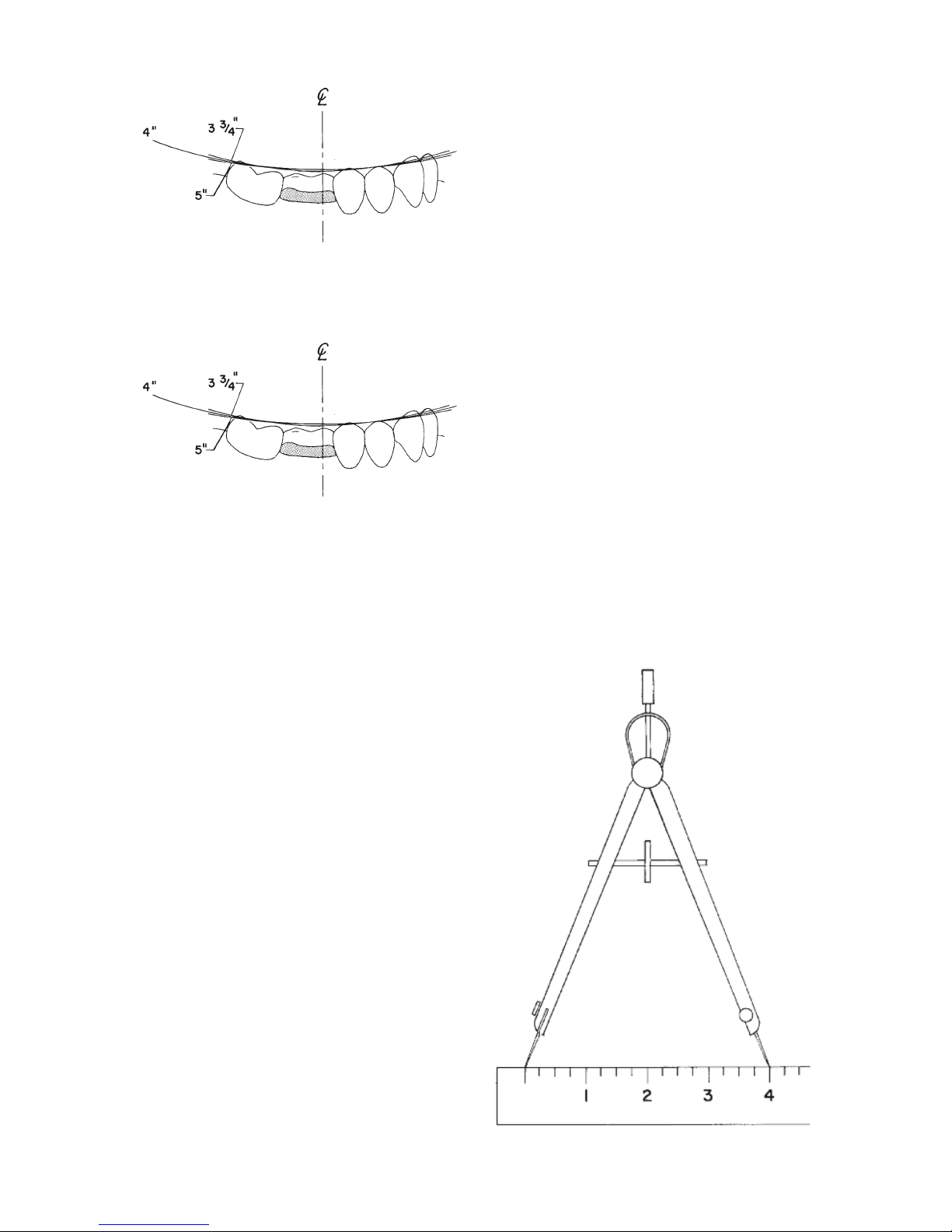
52
A view through both lower second
molars, fig. 98, illustrates the small
divergence between arcs of the same
three radii at the functional occlusal surfaces on the Curve of Wilson.
Insert a piece of graphite lead into the
bow compass, tighten thumbscrew, and
sharpen to a suitable point. Adjust the
bow compass to the radius selected (in
this instance 4”) (fig. 99).
Remove the upper cast, fig. 100, and
position the center point of the bow
compass, set at the 4” radius, on the
anterior survey point (A.S.P.) which is
usually the disto-incisal angle of the
cuspid. If the cuspid is worn flat, the
A.S.P. may be at the incisal edge. In any
event, this point must be selected as the
most desirable to “beam” the line and
plane of occlusion posteriorally. Once
selected, it is marked on the cuspid and
NOT CHANGED. With the center point
of the bow compass positioned on the
A.S.P., apply a long arc with the graphite
lead (about 3”) on the plastic record
card. The occlusal plane survey center
(
O.P.S.C.) will ultimately be located on
some point on this arc.
Select the posterior survey point (P.S.P.)
at the disto-buccal cusp tip of the last
lower molar (fig. 101). Should non
molars exist, replace the upper cast and
place soft modeling compound over the
lower ridge and close the articulator
until the incisal in contacts the incisal
guide in centric relation. Chill the compound and carve away any excess,
leaving only the compound contacting
the upper fossae (simulating the lower
buccal cusp). Remove the upper cast
and select a P.S.P. on the modeling
compound in the same manner as the
P.S.P. was selected on the last molar as
described above.
Position the center point of the bow
compass on the P.S.P. and apply an arc
with the graphite lead to intersect the
arc from the A.S.P.
Alternate to the molar P.S.P. is a position
on the condylar element of the articulat-
fig. 97
fig. 98
fig. 99
Page 55
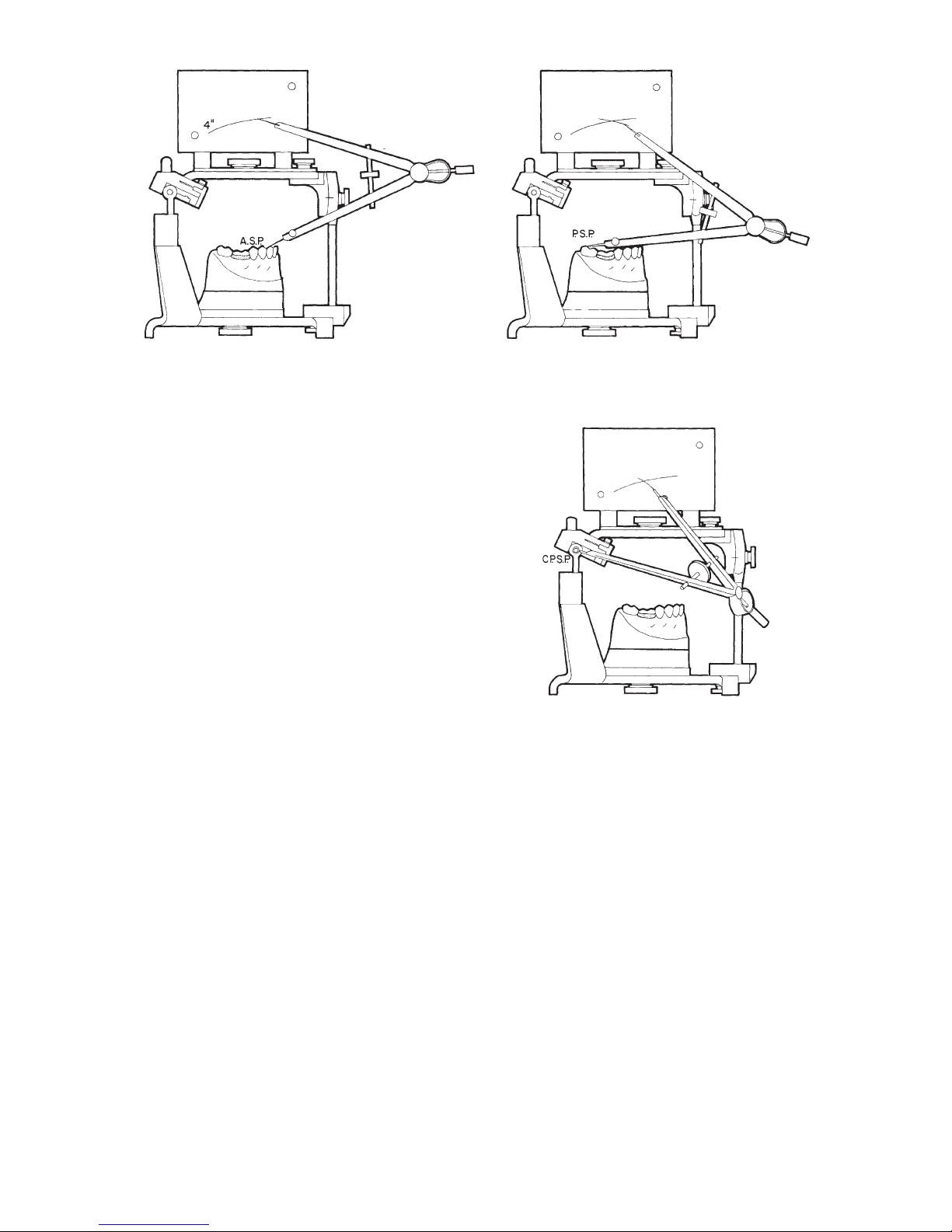
53
or at the middle of the anterior margin of
the hole on the lateral aspect of the
condyle (fig. 102). Position the center
point of the bow compass on the
condylar posterior survey point
(C.P.S.P.) and apply an arc with the
graphite lead to intersect the arc formed
from the A.S.P.
Continue with fig. 101 or 102 and substitute the needle point for the graphite
lead. Place the center point of the bow
compass adjusted to the 4” radius at the
intersection of arcs on the plastic record
card (initial occlusal plane survey center). Sweep the needle point over the
occlusal surfaces of the lower posterior
teeth to see how the arc conforms to the
existing occlusal plane. Shift this
occlusal plane survey center (O.P.S.C.)
on the long arc on plastic record card
(A.S.P. line) until the most acceptable
line and plane of occlusion is found. To
raise the line and plane of occlusion at
the distal end, move the point anterior to
the arc intersection.
To lower the line and plane of occlusion,
move the point posterior of the intersection. By trial and retrial, the ideal survey
center forming the most acceptable line
and plane of occlusion will be located.
Upon thorough and considered study,
locate the best possible line and plane
of occlusion for the lower posterior teeth
to harmonize with all other factors. The
center point of the bow compass is now
pierced into this ideal O.P.S.C. on the
plastic record card and circled with pencil or ink for subsequent relocation. It
may be advantageous to mark “R”
(right) in the upper corner of the plastic
index card for identification (fig. 103).
fig. 100
fig.101
fig.102
Page 56
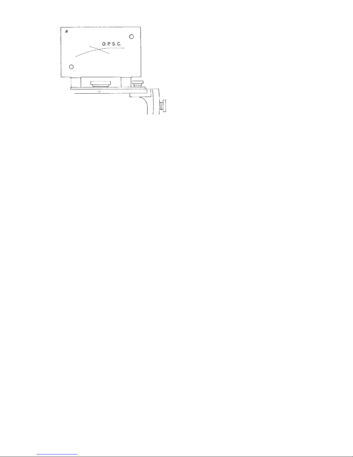
54
A
plastic record card is now secured to
the left side of the flag and marked “L.”
Repeat the procedure commencing with
figure 99 for the left survey.
The scribing knife, as furnished, is for
placement into the bow compass for
scribing or cutting plaster, compound, or
wax during the occlusal plane correction. The edge of the scribing knife may
be sharpened to individual requirements
as the edge supplied may not meet your
preference.
fig.103
Page 57

55
Articulators and other occlusal instrumentation exists to facilitate both the
diagnostic and treatment procedures for
the fabrication of restorations from the
single tooth to the complete dentition.
The question often arises regarding the
selection of the instrument of choice for
treating a particular prosthondontic
problem. To answer this question it is of
value to first briefly review the progress
that has taken place with the development of instruments for occlusal treatment and its impact on prosthodontic
techniques. This will also shed light on
why there are so many different instruments being used.
The earliest articulators, which were of
the hinge type, were developed primarily for full denture construction; i.e., to fill
the need for a mechanical device to
relate casts in an anatomically correct
position for the arrangement of artificial
teeth.
The next breakthrough resulted from the
desire to duplicate nature’s scheme and
provide patients with improved appearance and speech. This led to improved
denture teeth of anatomical form. Also,
understanding the anatomy and functions of the temporomandibular joints
and their relation to the occlusal scheme
brought about the development of articulators of anatomical dimensions with
some adjustment capability to simulate
the more pronounced condylar movements of a given patient. These articulators were adjusted primarily to interocclusal records.
Since the articulators were still not completely adequate, the mouth was found
to be the best articulator to fabricate
wax patterns and casting that would be
attached to the natural teeth and be
compatible with the excursive move-
ments of the jaw. These early articulators and occlusal schemes, that were
used to construct dentures resting on
mobile tissues, had to be supplemented
with more “in the mouth” procedures to
produce satisfactory results for fixed
restorations.
A great advance came in the late 1940s
and early fifties with the popularization
of the “indirect technique” i.e., the use
of impressions, casts and dies to duplicate the dentition so that most of the
work could be done in the laboratory at
a bench rather than “in the mouth.” The
introduction of improved dental materials to conveniently develop accurate
impressions and full arch working casts
coupled with the advent of high speed
cutting tools in dentistry popularized
restorative procedures for the general
public which heralded in a new era in
the development of instruments for
occlusal diagnosis and treatment.
Dentists sought more practical means to
accuratelly record and simulate the
movements of the jaw in order to deliver
better restorations in less time through
both improved laboratory work and
operating efficiency. The goal was to
produce better dentistry faster. It was
this effort and series of events that
resulted in the development of the
Dénar
®
Pantograph and Fully Adjustable
Articulator and subsequently the
Dénar®Mark II System and the Dénar
®
Two Instrument System.
Questions often asked are: “Should a
pantograph and fully adjustable articulator be used to fabricate a single gold
crown?” and “How extensive must the
restoration be before the use of a pantograph is indicated?” The simplest
response to these questions is as follows. If after tooth preparation, there
APPENDIX E
SELECTING INSTRUMENTS FOR OCCLUSAL TREATMENT
Page 58
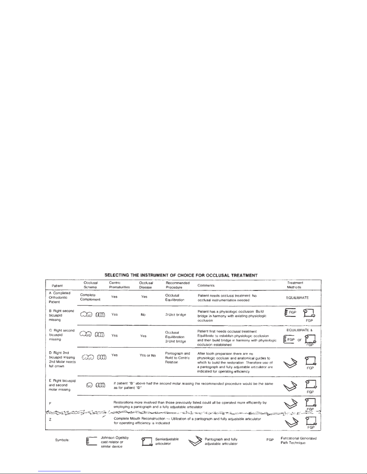
56
a
re sufficient unprepared teeth to provide positive stops and guidelines to
which to construct the restoration, the
restoration can be constructed in harmony with the existing occlusion and
the use of a pantograph is not necessarily indicated. On the other hand, if
after tooth preparation, there are insufficient guidelines in the remaining occlusion to which to construct the restoration, the restoration should be constructed in harmony with the patient’s
temporomandibular joint characteristics. These characteristics can be diagnosed most efficiently with a pantograph and fully adjustable articulator
although other treatment methods are
available.
In order to better understand the criteria
for selecting the instrument of choice for
occlusal treatment a discussion of the
examples on the chart below is helpful.
In this discussion reference is made primarily to the pantograph and fully
adjustable articulator; however the Mark
II System utilizing checkbites and supplemented with occlusal equilibration
and the functional generated path tech-
n
ique, when indicated, can be used to
produce excellent results.
To keep the discussion pertinent, it is
assumed that none of the patients in the
following examples have temporomandibular joint disease.
PATIENT A is a finished orthodontic
patient who has a full complement of
teeth in good alignment. The patient has
a slight occlusal prematurity which has
triggered facial pain. The patient has a
pathologic occlusion and occlusal treatment is indicated. The treatment is primarily occlusal equilibration. An articulator can be used in diagnostic procedures although it is not always needed
in treatment.
PATIENT Z on the other hand exhibits
many missing teeth. The remaining teeth
are badly broken down. There is extensive drifting of teeth and the occlusion is
totally disorganized. This patient
requires a complete mouth reconstruction. This restoration could be fabricated
most efficiently by employing a pantograph and fully adjustable articulator.
Page 59

57
A
t what point between the two extremes
represented by Patient’s A and Z is the
use of a pantograph and fully adjustable
articulator indicated? The answer to this
question is presented in the following
discussion of Patient’s B through E who
exhibit increasingly complex occlusal
problems.
PATIENT B has a missing right second
bicuspid and a minor centric prematurity. There are no symptoms which can be
related to the occlusal condition. The
patient has a physiologic occlusion. The
recommended treatment is a three unit
bridge. To perform this laboratory procedure the cast can be accurately related at the correct vertical dimension in a
nonrigid cast relating device such as a
Johnson Olgesby Articulator (which has
springs for condylar posts so that the
casts can be gnashed together) and the
bridge fabricated in harmony within the
anatomical guides provided by the prevailing physiologic occlusion. This procedure could be used successfully if the
restoration were one, two or three
crowns on one, two or three of the teeth
involved in the bridge. Alternately a
method preferred by many operators is
the use of the functional generated path
technique (FGP) to fabricate this prosthesis.
PATIENT C has the same mouth conditions and occlusal scheme as Patient B
with the exception that the occlusal
scheme has triggered bruxism and the
sequelae of bruxism (occlusal disease).
This patient first requires occlusal treatment and in addition, a three unit bridge.
The recommended procedure is to first
equilibrate the natural occlusion to estab-
l
ish a physiologic occlusion and subsequently fabricate the three unit bridge (or
inlays) as outlined for Patient B.
PATIENT D has the right second bicuspid missing and in addition the right
second molar has indications for full
coverage. Slight occlusal discrepancies
exist. Whether this patient has related
symptoms or not, the procedure many
dentists would recommend when this
many teeth are involved in the prosthesis is to fabricate the restoration in centric relation. Since after tooth preparations there are no more anatomical controls in the occlusion on the right side of
the mouth to use as anatomical guides
to which to fabricate the restoration,
then the next most posterior anatomical
control, the temporomandibular joint, is
used as a control for the fabrication of
the prosthesis (see figures 26C and 27
and related discussion). This could be
accomplished most efficiently by utilizing a pantograph and fully adjustable
articulator.
PATIENT E. If Patient B had in addition
to the missing right second bicuspid the
right second molar missing, the recommended treatment would be the same
as for Patient D.
Restorations more involved than those
previously listed could all be operated
more efficiently by employing a pantograph and fully adjustable articulator or
alternately by means of the Mark II
System supplemented with the functional generated path technique and/or
occlusal equilibration as described
above.
Page 60
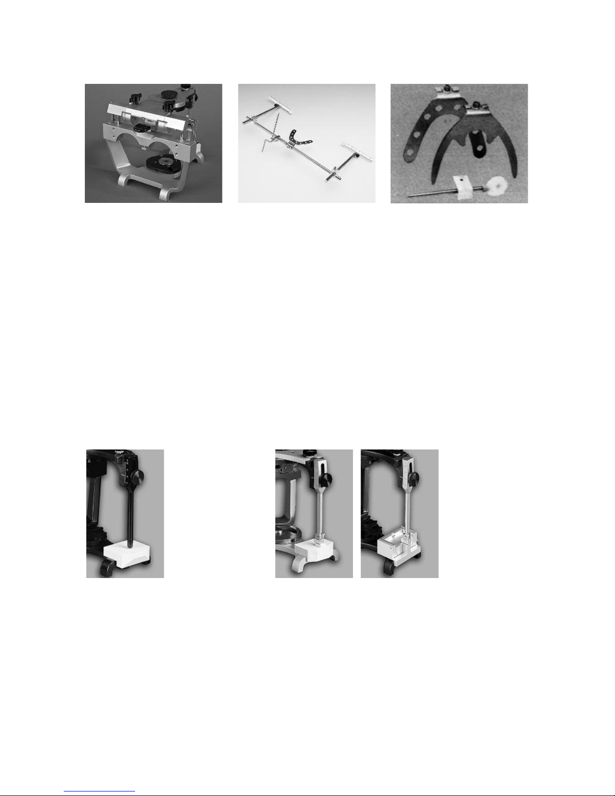
58
APPENDIX F
Dénar®Semiadjustable
Articulator
Mark II Articulator
(includes #300197 pin and
D41AB platform)
Mark II-P2T2 Articulator
(includes #110093 pin and
D41 platform)
Mark II-P2T3 Articulator
(includes #110093 pin and
D46 adjustable incisal table)
P1 (#300197)-round incisal pin
functions with the D41AB incisal
Platform which has a detent in
its superior surface.
P4 (#300270) round short
Incisal Pin functions with the
D49 Incisal Platform which has a
flat surface
P2 (#11093) Adjustable Incisal Pin
functions with the D46 Adjustable
Incisal Table and the D41 custom
Incisal Platform
Earbow/Facebow D31AB Bite Fork - Standard
Dentulous
Bite Fork - Edentulous
Anterior Reference Pointer
Page 61
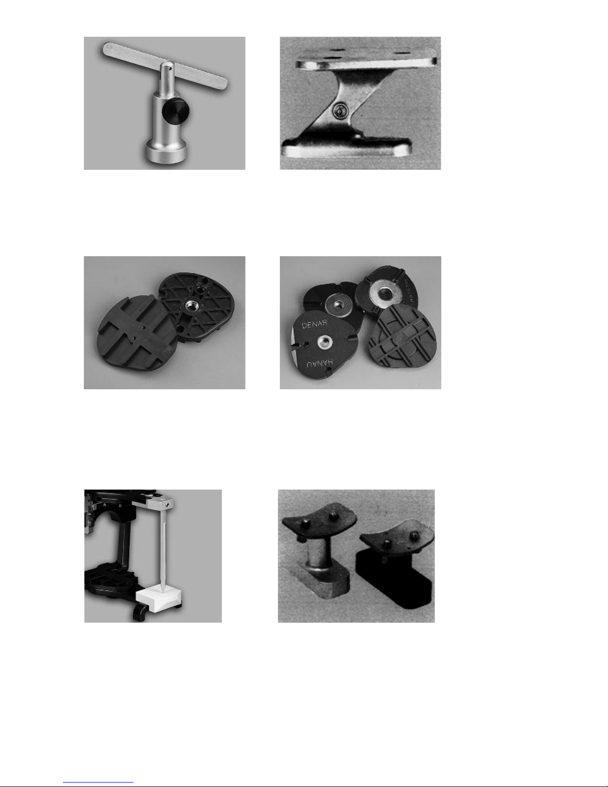
59
Maxillary Cast Support Remount Record Jig
Mounting Plates Magnetic Mounting System
Dawson Fossa-Guide Pin Pantograph Mounting Fixture
Page 62

60
Your Whip Mix®Articulator is a precision
instrument and requires care and maintenance. Periodic cleaning and lubricating as described below will assure prolonged life and dependable service from
the instrument. Failure to follow these
instructions will void your warranty.
CLEANING
Use a mild soap and water solution with
the aid of a brush to dissolve accumulations of wax and to wash away carborundum grit. Then air dry and lubricate. DO NOT use strong detergents,
alkalines, gasoline or naptha as cleaning
agents.
LUBRICATION
Lubricate the working and bearing components with thin film of sewing
machine or high speed handpiece type
oil. Wipe off excess oil to prevent accumulations of dust or grit.
A thin coating of petroleum jelly must be
applied to all articulator surfaces that
will be contacted by the gypsum mounting material
STORAGE
Store the articulator in a clean, dry
atmosphere free of plaster and carborundum dust; away from acids, alkalies or corrosive medicaments. Wait a
full day after mounting casts before
storing the articulator in a carrying
case or corrugated carton. Moisture
dissipation from the stone in an
enclosed area causes alkalinity of the
stone mixture which can damage the
articulator surface.
WARRANTY
Whip Mix Corporation warrants the
articulator system to be free from
defects in material and/or workmanship
for a period of one year. In the event of
a defect, please notify the factory in
writing of the defect prior to returning
the instrument. Whip Mix will, at its
option, either repair, replace or issue
credit for such defects.
Because Whip Mix Corporation is continually advancing the design of its
products and manufacturing methods, it
reserves the right to improve, modify or
discontinue products at any time, or to
change specifications or prices without
notice and without incurring obligations.
APPENDIX G
ARTICULATOR
CARE AND MAINTENANCE
Page 63

Page 64

Page 65

Page 66

Page 67

Page 68
FN 80471-F AE R1008
Whip Mix Corporation - West
1730 East Prospect Rd., Suite 101
Fort Collins, CO 80525
Toll-Free: 1-800-201-7286
Fax: 1-970-472-1793
www.whipmix.com
Denar®and logo are registered
trademarks of Whip Mix Corporation.
©2008 Whip Mix Corporation
Dénar
®
The Dénar
®
Mark II System TECHNIQUE MANUAL
 Loading...