

Page 1
M3 10.0 in-lbs - 1.0 Nm
23.0 in-lbs
M5 44.5 in-lbs 3.5 ft-lbs 5.0 Nm
M6 78.0 in-lbs 6.5 ft-lbs 9.0 Nm
M8 - 13.5 ft-lbs 18.0 Nm
M10 - 30.0 ft-lbs 41.0 Nm
M12 - 52.0 ft-lbs 71.0 Nm
in-lbs
Instruction Manual
LAH.06.10200
Yamaha Tenere 700
Auxiliary Light Mounting Bracket
Instruction Rev00
Thank you for choosing DENALI
We know you would rather be riding your bike than wrenching on it, so we go the extra
mile to make sure our instructions are clear and as easy to understand as possible. If
you have any questions, comments, or suggestions don’t hesitate to give our gear
experts a call at 401.360.2550 or visit WWW.DENALIELECTRONICS.COM
Please Read Before Installing
DENALI products should always be installed by a qualified motorcycle technician. If
you are unsure of your ability to properly install a product, please have the product
installed by your local motorcycle dealer. DENALI takes no responsibility for damages
caused by improper installation. Caution: When installing electronics it is extremely
important to pay close attention to how wires are routed, especially when mounting
products to the front fender, front forks, or fairing of your motorcycle. Always be sure
to turn the handlebars fully left, fully right, and fully compress the suspension to
ensure the wires will not bind and have enough slack for your motorcycle to operate
properly.
Installation Tips
We strongly recommend using medium strength liquid thread locker on all screws,
nuts, and bolts. It is also important to ensure that all hardware is tightened to the
proper torque specifications as listed in your owner’s manual. For included accessory
hardware please refer to the default torque specifications provided below. Inspect all
hardware after the first 30 miles to ensure proper torque specifications are
maintained.
Hardware Sizing Guide
Not sure what size bolt you have? Use this ruler to measure screws, bolts, spacers, etc.
Remember, the length of a screw or bolt is measured from the start of the “mounting
surface” to the end of the screw, so only include the screw head when measuring
countersunk screws.
0mm
10 20
DENALIELECTRONICS.COM
ft-lbs NmBolt Size
30
50
40
70
60
80
90
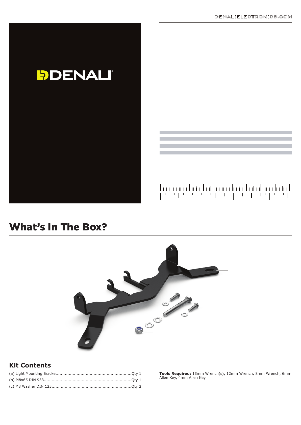
What’s In The Box?
0in 1 2
(b)
(e)
(f)
(c)
(d)
3
(a)
Kit Contents
(a) Light Mounting Bracket.........................................................Qty 1
(b) M8x65 DIN 933...................................................................Qty 1
(c) M8 Washer DIN 125.............................................................Qty 2
(d) M8 Nut DIN 985..................................................................Qty 1
(e) M6x20 ISO 7380.................................................................Qty 2
(f) M6 Washer DIN 125..............................................................Qty 2
Tools Required: 13mm Wrench(s), 12mm Wrench, 8mm Wrench, 6mm
Allen Key, 4mm Allen Key
Page 2
1. Accessing The Mounting Points
Fairing
Stay
Light Mount
Light Mount
DENALIELECTRONICS.COM
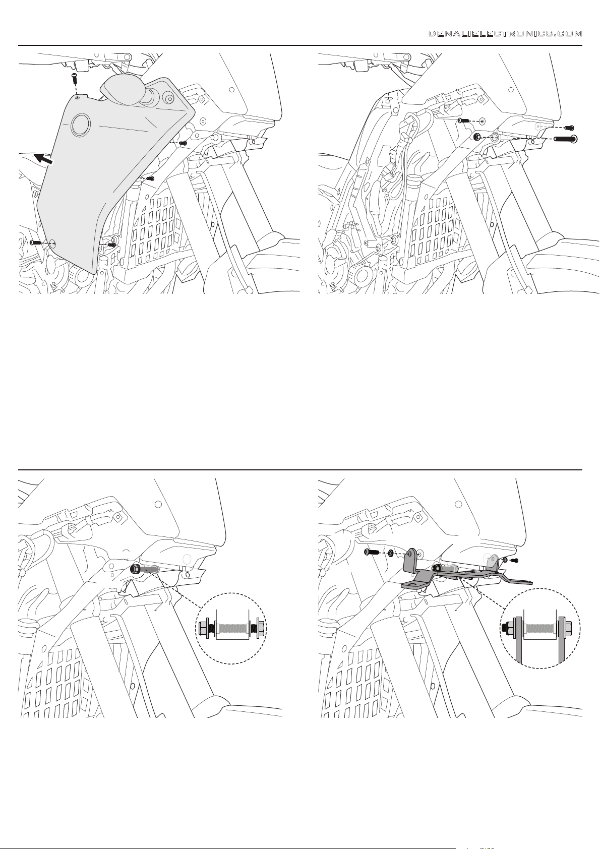
1.1 - Removing The Side Panels
The left and right side panels will need to be removed from the motorcycle for
installation of the light mounting bracket. Each side panel is secured to the bike by three
bolts, three screw-type plastic retainer rivets as well as a series of mounting tabs.
Step One: Remove the three plastic retainer rivets from the inside of each side panel.
To do this, use a 8mm wrench to turn the bolt head a quarter turn counterclockwise,
then pull the retainer rivets from the panels.
Step Two: Use a 8mm wrench to remove the three bolts from the outside of each
panel.
Step Three: Slide each side panel towards the rear of the motorcycle to release the
panels mounting tabs from the slots on the motorcycle. The turn signals will need to be
disconnected once the panel is partially removed.
2. Mounting The Bracket
1.2 - Removing The OEM Hardware
Step One: Use a 8mm wrench to remove the silver flange head bolt from either side of
the headlight assembly. There will also be a bushing in each mounting hole, be sure to
keep these as they will be re-used during installation.
Step Two: Use a 12mm wrench and 6mm allen key to remove the lower fairing stay
bolt located between the fork legs. This mounting point will also have a bushing on
either side, again be sure to keep them as they will be re-used during installation.
Fairing
Stay
2.1 - Installing The Fairing Stay Bolt
Step One: Install the new M8x65 bolt (b) and washers (c) into low fairing stay, make
sure to re-use the OEM bushings.
Step Two: Thread the M8 nut (d) onto the M8x65 bolt (b) just far enough that it will
not fall off, the nut will be fully tightened during the final step.
2.2 - Installing The Bracket
Step One: Slide the light mounting bracket (a) onto the previously installed M8x65 bolt
(b). The OEM bushings should sit on the inside of the light mounting bracket’s arms and
the M8 washers (c) should sit on the outside of the arms.
Step Two: Reinstall the OEM bushings into the upper mounting points and hinge the
light mounting bracket (a) upwards until the upper mouting tabs are aligned, then use
a 4mm allen key to install the M6x20 bolts (e), & washers (f).
Step Three: Fully tighten the M6x20 bolts at both upper mounting points, then use two
13mm wrenches to fully tighten the M8x65 bolt & nut at the lower mounting point.
 Loading...