

Demon AVR-X6200W Service manual
e
SERVICE MANUAL
e
D&M Holdings Inc.
MODEL JP E3 E2 EK EA E1 E1C E1K
Ver. 1
AVR-X6200W
INTEGRATED NETWORK AV RECEIVER
P P P
• For purposes of improvement, specications and design are subject to change without notice.
Please use this service manual with referring to the operating instructions without fail.
•
Some illustrations using in this service manual are slightly different from the actual set.
•

CONTENTS
ABOUT THIS MANUAL
What you can do with this manual
Using Adobe Reader (Windows version)
SAFETY PRECAUTIONS
NOTE FOR SCHEMATIC DIAGRAM
NOTE FOR PARTS LIST
Instructions for handling semi-conductors and optical unit
1. Ground for Human Body
2. Ground for Workbench
TECHNICAL SPECIFICATIONS
DIMENSION
CAUTION IN SERVICING
Initializing This Unit
JIG FOR SERVICING
DISASSEMBLY
1. FRONT PANEL ASSY
2. RADIATOR ASSY
3. SMPS ASSY
4. POWER TRANS
5. BACK PANEL ASSY
SPECIAL MODE
Special mode setting button
1. Version Display Mode
2. Selecting the Mode for Service-related Operations
PROTECTION DIAGRAM
DIAGNOSTIC PATH DIAGRAM
3. PANEL / REMOTE LOCK Selection Mode
4. Protection Pass Mode
5. CY920 Reboot Mode
6. CY920 Initialization Mode
JIG FOR SERVICING
Procedure after Replacing the Printed circuit boards.
Procedure after Replacing the Microprocessor, etc.
FIRMWARE UPDATE PROCEDURE
1. Updating via USB
2. Updating via DPMS
ADJUSTMENT
SURROUND MODES AND PARAMETERS
TROUBLE SHOOTING
1. POWER
2. Analog video
3. HDMI/DVI
4. AUDIO
5. Network/Bluetooth/USB
6. SMPS
..............................................................................10
.............................................................................100
..............................................................................105
................................................................................113
................................................................3
...........................................3
...................................4
...............................................................6
..............................................7
................................................................7
......................................................7
........................................................7
.....................................................9
...........................................................11
.................................................................11
..................................................................11
..........................................................................12
............................................................14
.................................................................15
.........................................................................16
....................................................................17
..............................................................18
.........................................................................19
..................................................19
........................................................20
...........24
......................................................25
............................................30
............................74
........................................................75
..........................................................75
..................................................76
..................................................................77
...........79
..............79
............................................80
...............................................................80
............................................................89
...........................................................................96
..................................97
..............................................................100
....................................................................101
.........................................................................103
..................................................108
...7
Audio Check PASS
CLOCK FLOW & WAVE FORM IN DIGITAL BLOCK
LEVEL DIAGRAM
BLOCK DIAGRAM
A.AUDIO / Z2,3HPF DIAGRAM
DIGITAL AUDIO / NETWORK DIAGRAM
VIDEO DIAGRAM
POWER DIAGRAM
CPU DIAGRAM
PRINTED CIRCUIT BOARDS
SCHEMATIC DIAGRAMS (01/33)
SCH01_DIGITAL CONNECT
SCH02_DIR ADC ZONEDAC
SCH03_AUDIO PLD
SCH04_DSP1
SCH05_DSP2
SCH06_DSP3
SCH07_DSP4
SCH08_MAIN CPU
SCH09_SUB CPU
SCH10_DECODER
SCH11_HDMI SW1
SCH12_HDMI SW2
SCH13_IP SCALER
SCH14_IP SCALER DDR
SCH15_VIDEO PLD
SCH16_HDMI RX TX
SCH17_HDMI SUPPLY
SCH18_NETWOR
SCH19_AUDIO VIDEO CONNECT
SCH20_AUDIO VOLUME
SCH21_PREOUT
SCH22_VIDEO SELECTOR
SCH23_CONNECT
SCH24_ZONEDAC ADC
SCH25_MAIN DAC
SCH26_FRONT HDMI USB
SCH27_SPEAKER
SCH28_REG
SCH29_FRONT
SCH30_SMPS
SCH31_AMP CONNECT
SCH32_232C PHONO
SCH33_POWER AMP
EXPLODED VIEW
PACKING VIEW
SEMICONDUCTORS
....................................................................................170
1. IC's
2. FL DISPLAY
.................................................................115
.....................................................................117
...................................................................125
...............................................125
.................................126
...................................................................127
..................................................................128
.......................................................................129
....................................................130
.............................................135
....................................................135
...................................................136
...............................................................137
.........................................................................138
.........................................................................139
.........................................................................140
.........................................................................141
.................................................................142
....................................................................143
..................................................................144
................................................................145
................................................................146
..................................................................147
.........................................................148
................................................................149
..............................................................150
...........................................................151
...................................................................152
...........................................153
........................................................154
.....................................................................155
......................................................156
..................................................................157
.........................................................158
.................................................................159
.....................................................160
...................................................................161
...........................................................................162
.......................................................................163
.........................................................................164
.........................................................165
............................................................166
.............................................................167
....................................................................168
.......................................................................169
................................................................170
......................................................................192
...................116
2
ABOUT THIS MANUAL
Read the following information before using the service manual.
What you can do with this manual
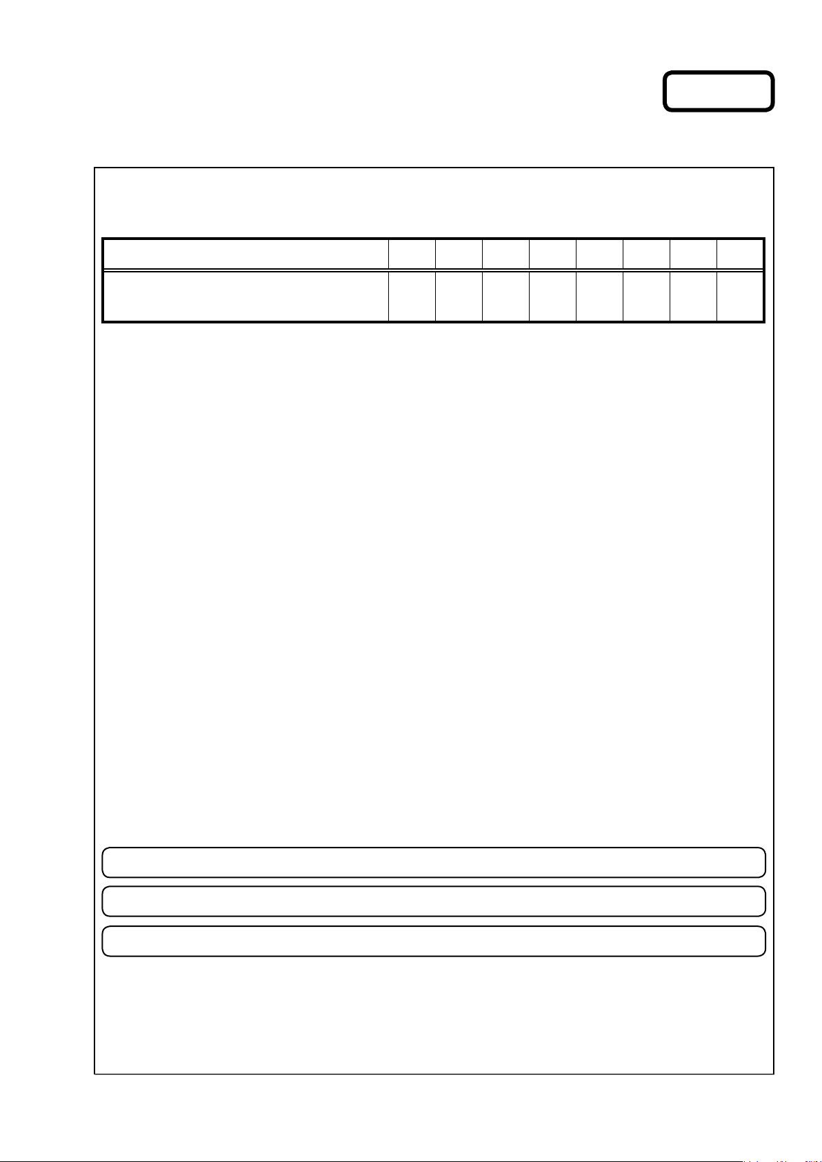
Search for a Ref. No. (phrase)
(Ctrl+Shift+F)
You can use the search function in Acrobat Reader to
search for a Ref. No. in schematic diagrams, printed
wiring circuit diagrams, block diagrams, and parts
lists.
1. Press
• The Search window appears.
2. Enter the Ref. No. you want to search for in the
Search window, and then click the
• A list of search results appears.
Ctrl+Shift+F
Shift
Ctrl
on the keyboard.
F
Search
button.
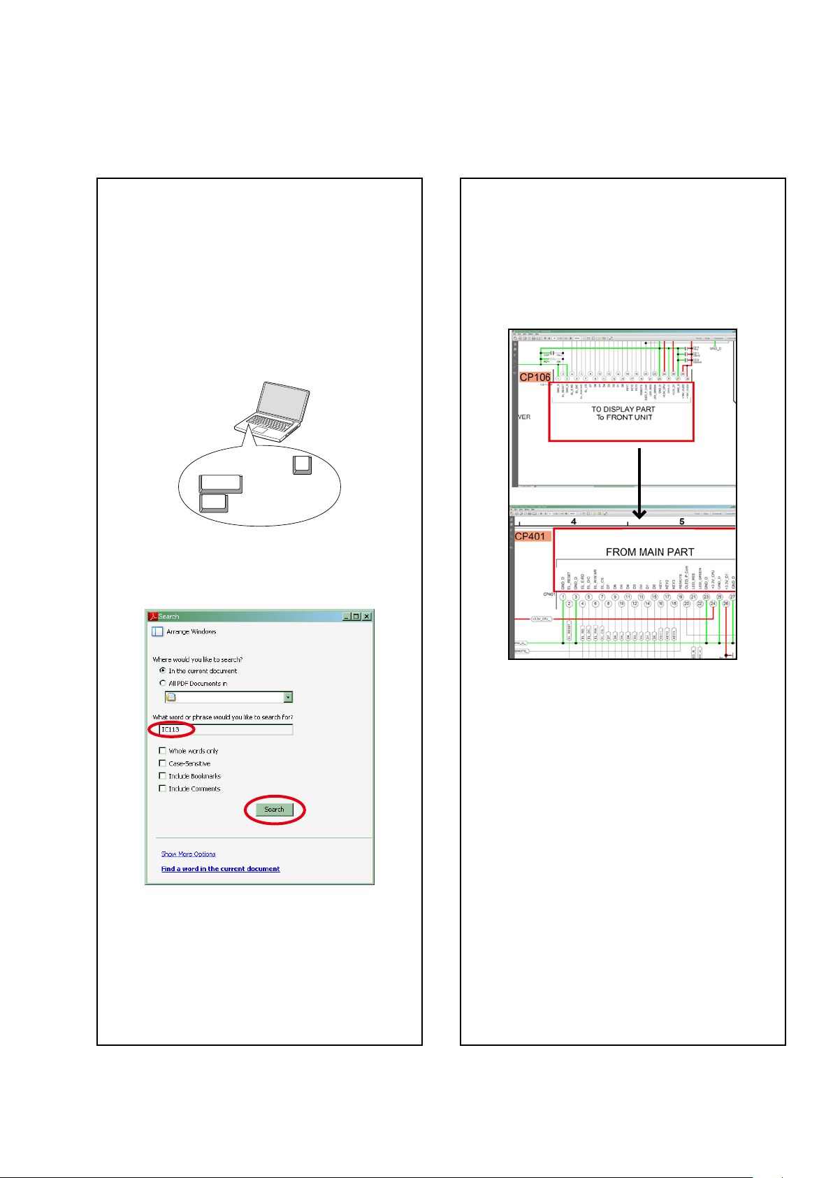
Jump to the target of a schematic diagram
connector
Click the Ref. No. of the target connector in the red
box around a schematic diagram connector.
•The screen jumps to the target connector.
CP401
v
CP106
3. Click an item on the list.
• The screen jumps to the page for that item, and the
search phrase is displayed.
• Page magnication stays the same as before the
jump.
3
Using Adobe Reader (Windows version)
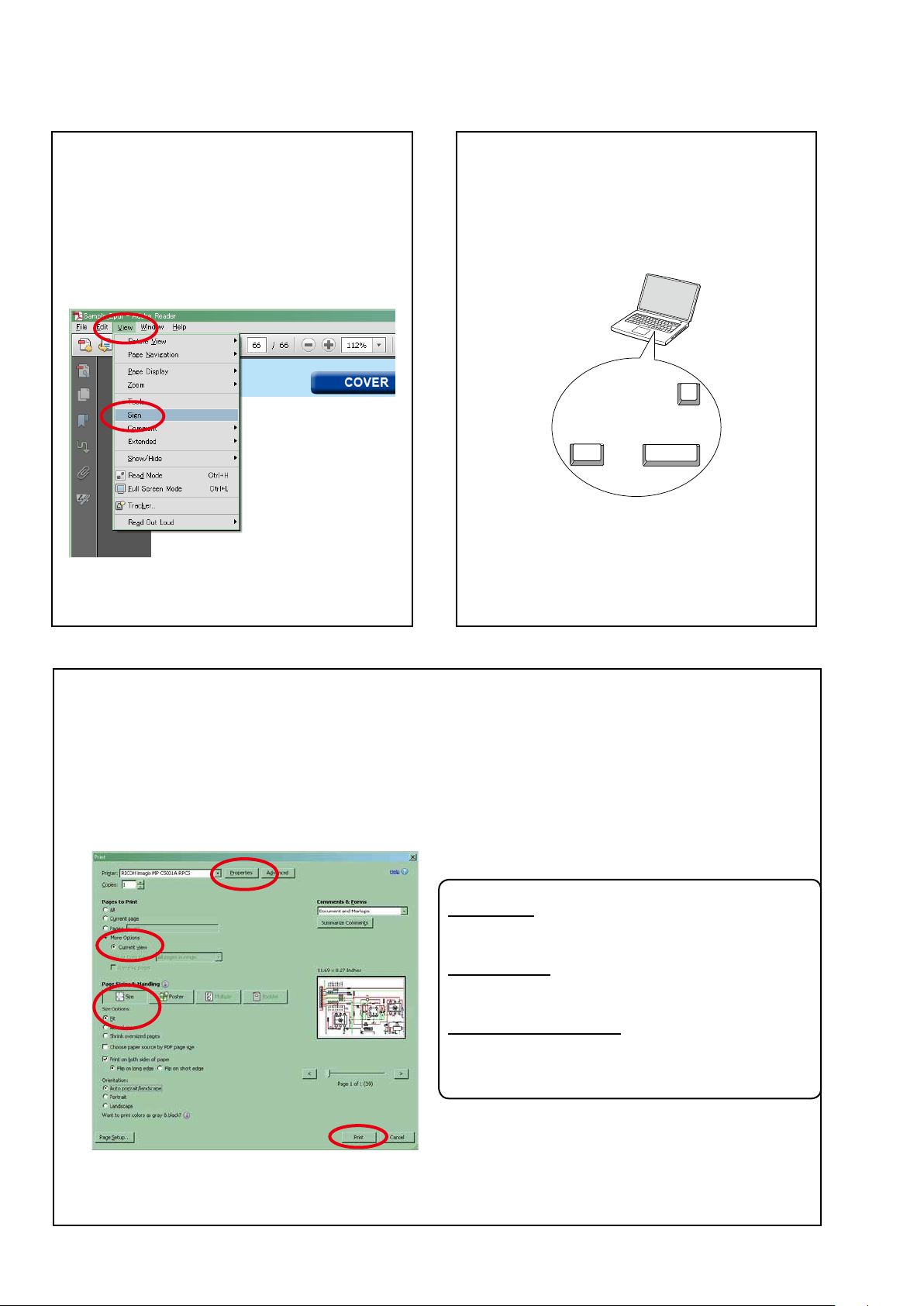
Add notes to this data (Sign)
The Sign function lets you add notes to the data in
this manual.
Save the le once you have nished adding notes.
[Example using Adobe Reader X]
"View"
On the
• The Sign pane appears.
[Example using Adobe Reader 9]
On the
menu, click
"Document"
"Sign"
menu, click
.
"Sign"
.
Magnify schematic / printed circuit board
diagrams - 1
(Ctrl+Space, mouse operation)
Ctrl+Space
Press
mouse to select the area you want to view.
• The selected area is magnied.
• When you want to move the area shown, hold
down
• When you want to show a full page view, press
Ctrl+0
on the keyboard and drag the
0
Ctrl Space
Space
and drag the mouse.
on the keyboard.
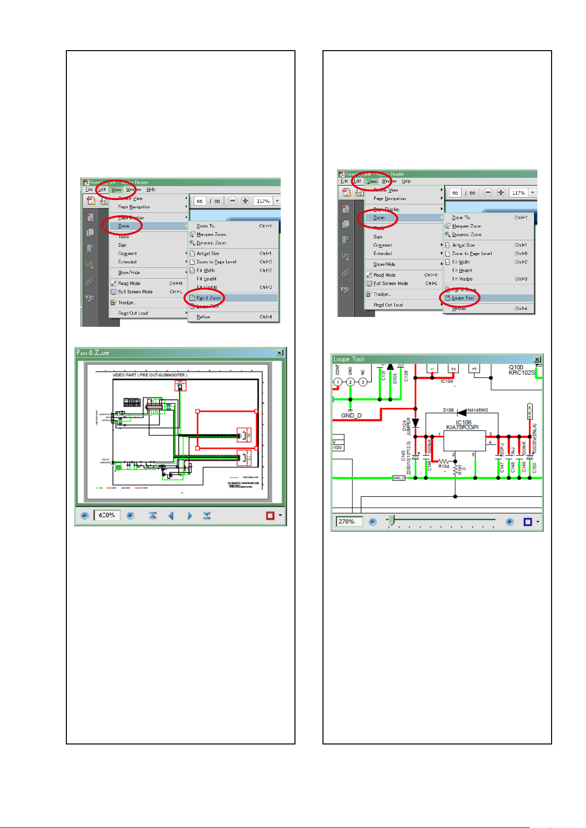
Print a magnied part of the manual
The Properties dialog box and functions will vary depending on your printer.
1. Drag the mouse to magnify the part you want to print.
"File"
2. On the
3. Congure the following settings in the Print dialog box.
menu, click
"Print"
.
• Properties
Click this button and check that the printer is set to a
suitable paper size.
• Page to print
Select the following checkbox.
"More Options" : "Current View"
• Page Sizing & Handling
Select the following checkbox.
"Size" / "Size Options" : "Fit"
4. Click the
Print
button to start printing.
4
Magnify schematic / printed circuit board
diagrams - 2
(Pan & Zoom function)
The Pan & Zoom function lets you see which part of
a magnied diagram is being shown in a separate
window.
[Example using Adobe Reader X]
On the
click
"View"
"Pan & Zoom"
menu, point to
.
"Zoom"
, and then
Magnify schematic / printed circuit board
diagrams - 3
(Loupe Tool function)
The Loupe Tool function lets you magnify a specic
part of a diagram in a separate window.
[Example using Adobe Reader X]
On the
"Loupe Tool"
click
"View"
menu, point to
.
"Zoom"
, and then
• The Pan & Zoom window appears on the screen.
[Example using Adobe Reader 9]
On the
and then click
"Tools"
menu, point to
"Pan & Zoom Window"
"Select & Zoom"
.
,
• The Loupe Tool window appears on the screen.
[Example using Adobe Reader 9]
"Tools"
On the
and then click
menu, point to
"Loupe Tool Window"
"Select & Zoom"
.
,
5

SAFETY PRECAUTIONS
The following items should be checked for continued protection of the customer and the service technician.
leakage current check
Before returning the set to the customer, be sure to carry out either (1) a leakage current check or (2) a line to chassis
resistance check. If the leakage current exceeds 0.5 milliamps, or if the resistance from chassis to either side of the
power cord is less than 460 kohms, the set is defective.
Be sure to test for leakage current with the AC plug in both polarities, in addition, when the set's power is in each state
(on, off and standby mode), if applicable.
CAUTION
Please heed the following cautions and instructions during servicing and
inspection.
◎ Heed the cautions!
Cautions which are delicate in particular for servicing are
labeled on the cabinets, the parts and the chassis, etc. Be
sure to heed these cautions and the cautions described in
the handling instructions.
◎ Cautions concerning electric shock!
(1) An AC voltage is impressed on this set, so if you touch
internal metal parts when the set is energized, you
may get an electric shock. Avoid getting an electric
shock, by using an isolating transformer and wearing
gloves when servicing while the set is energized, or
by unplugging the power cord when replacing parts,
for example.
(2) There are high voltage parts inside. Handle with extra
care when the set is energized.
◎ Caution concerning disassembly and assembly!
Through great care is taken when parts were
manufactured from sheet metal, there may be burrs on
the edges of parts. The burrs could cause injury if ngers
are moved across them in some rare cases. Wear gloves
to protect your hands.
◎ Use only designated parts!
The set's parts have specic safety properties (re
resistance, voltage resistance, etc.). Be sure to use parts
which have the same properties for replacement. The
burrs have the same properties. In particular, for the
important safety parts that are indicated by the z mark
on schematic diagrams and parts lists, be sure to use the
designated parts.
◎ Be sure to mount parts and arrange the wires
as they were originally placed!
For safety seasons, some parts use tapes, tubes or other
insulating materials, and some parts are mounted away
from the surface of printed circuit boards. Care is also
taken with the positions of the wires by arranging them
and using clamps to keep them away from heating and
high voltage parts, so be sure to set everything back as it
was originally placed.
◎ Make a safety check after servicing!
Check that all screws, parts and wires removed or
disconnected when servicing have been put back in
their original positions, check that no serviced parts have
deteriorate the area around. Then make an insulation
check on the external metal connectors and between the
blades of the power plug, and otherwise check that safety
is ensured.
(Insulation check procedure)
Unplug the power cord from the power outlet, disconnect
the antenna, plugs, etc., and on the power. Using a 500V
insulation resistance tester, check that the insulation
resistance value between the inplug and the externally
exposed metal parts (antenna terminal, headphones
terminal, input terminal, etc.) is 1MΩ or greater. If it is
less, the set must be inspected and repaired.
CAUTION
Concerning important safety
parts
Many of the electric and the structural parts used in the
set have special safety properties. In most cases these
properties are difcult to distinguish by sight, and the use
of replacement parts with higher ratings (rated power
and withstand voltage) does not necessarily guarantee
that safety performance will be preserved. Parts with
safety properties are indicated as shown below on the
wiring diagrams and the parts list in this service manual.
Be sure to replace them with the parts which have the
designated part number.
(1) Schematic diagrams Indicated by the
(2) Parts lists Indicated by the
The use of parts other than the designated parts could
cause electric shocks, res or other dangerous situations.
z
mark.
z
mark.
6
NOTE FOR SCHEMATIC DIAGRAM
WARNING:
Parts indicated by the z mark have critical characteristics. Use ONLY replacement parts recommended by the manufacturer.
CAUTION:
Before returning the set to the customer, be sure to carry out either (1) a leakage current check or (2) a line to chassis resistance check. If
the leakage current exceeds 0.5 milliamps, or if the resistance from chassis to either side of the power cord is less than 460 kohms, the set
is defective.
WARNING:
DO NOT return the set to the customer unless the problem is identied and remedied.
NOTICE:
ALL RESISTANCE VALUES IN OHM. k=1,000 OHM / M=1,000,000 OHM
ALL CAPACITANCE VALUES ARE EXPRESSED IN MICRO FARAD, UNLESS OTHERWISE INDICATED. P INDICATES MICRO-MICRO FARAD. EACH
VOLTAGE AND CURRENT ARE MEASURED AT NO SIGNAL INPUT CONDITION. CIRCUIT AND PARTS ARE SUBJECT TO CHANGE WITHOUT
PRIOR NOTICE.
NOTE FOR PARTS LIST
1. Parts indicated by
2. When ordering a part, make a clear distinction between "1" and "I" (i) to avoid mis-supplying.
3. A part ordered without specifying its part number can not be supplied.
4. Part indicated by " ★ " mark is not illustrated in the exploded view.
WARNING: Parts indicated by the z mark have critical characteristics. Use ONLY replacement parts recommended by the manufacturer.
"nsp"
on this table cannot be supplied.
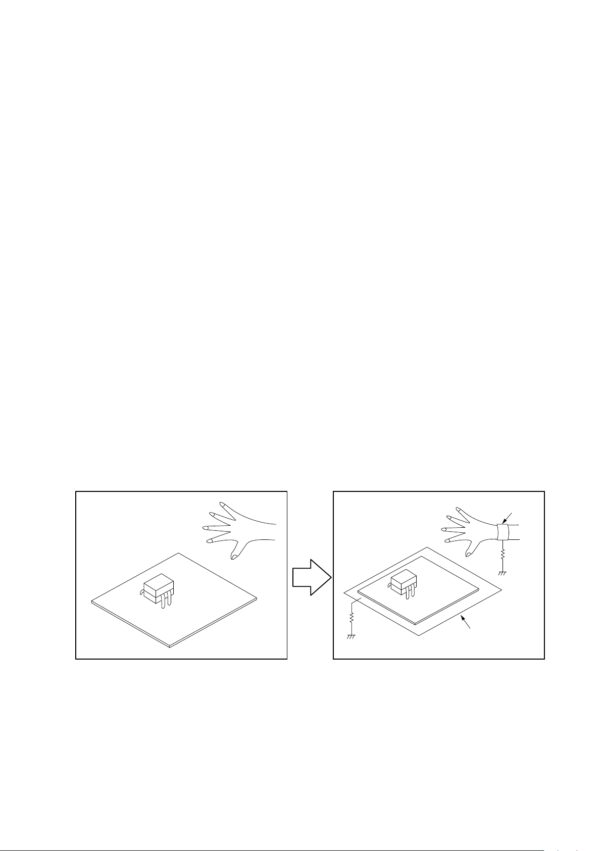
INSTRUCTIONS FOR HANDLING SEMI-CONDUCTORS AND OPTICAL UNIT
Electrostatic breakdown of the semi-conductors or optical pickup may occur due to a potential difference caused by
electrostatic charge during unpacking or repair work.
1. Ground for Human Body
Be sure to wear a grounding band (1 MΩ) that is properly grounded to remove any static electricity that may be charged
on the body.
2. Ground for Workbench
Be sure to place a conductive sheet or copper plate with proper grounding (1 MΩ) on the workbench or other surface,
where the semi-conductors are to be placed. Because the static electricity charge on clothing will not escape through the
body grounding band, be careful to avoid contacting semi-conductors with your clothing
<Incorrect>
CBA
<Correct>
1MΩ
Grounding Band
1MΩ
CBA
Conductive Sheet or
Copper Plate
7

Personal notes:
8

TECHNICAL SPECIFICATIONS
Audio section
n
• Power amplier
Rated output :
Front:
140W+140W (8Ω, 20Hz - 20kHz with 0.05% T.H.D.)
175W+175W (6Ω, 1kHz with 0.7% T.H.D)
Center :
140W (8Ω, 20Hz - 20kHz with 0.05% T.H.D.)
175W (6Ω, 1 kHz with 0.7 % T.H.D.)
Surround :
140W+140W (8Ω, 20 Hz - 20 kHz with 0.05% T.H.D.)
175W+175W (6Ω, 1 kHz with 0.7 % T.H.D.)
Surround back / Height1 / Front wide / Height2:
140W+140W (8Ω, 20 Hz - 20 kHz with 0.05% T.H.D.)
175W+175W (6Ω, 1 kHz with 0.7 % T.H.D.)
Rated output :
160 W x 2-channel (8 Ω)
250 W x 2-channel (4 Ω)
Output connectors : 4 - 16 Ω
Analog section
n
Input sensitivity/Input impedance : 200 mV / 47 kΩ
Frequency response : 10 Hz - 100 kHz — +1, -3 dB(Direct mode)
S/N : 102 dB(IHF-A weighted, Direct mode)
Distortion : 0.005 % (20 Hz – 20 kHz) (Direct mode)
Rated output : 1.2 V
Digital section
n
D/A output : Rated output — 2 V (at 0 dB playback)
Digital input : Format — Digital audio interface
Phono equalizer section
n
Input sensitivity : 2.5 mV
RIAA deviation : ±1 dB (20 Hz to 20 kHz)
S/N : 74 dB (IHF-A)
Distortion factor : 0.03 % (1 kHz, 3 V)
Video section
n
• Standard video connectors
Input/output level and impedance :
Frequency response : 5 Hz - 10 MHz — 0, -3 dB
• Color component video connector
Input/output level and impedance :
Frequency response : 5 Hz - 60 MHz — 0, -3 dB
Total harmonic distortion — 0.008 % (1 kHz, at 0 dB)
S/N ratio — 102 dB
Dynamic range — 100 dB
1 Vp-p, 75 Ω
Y signal — 1 Vp-p, 75 Ω
PB / CB signal — 0.7 Vp-p, 75 Ω
PR / CR signal — 0.7 Vp-p, 75 Ω
Tuner section
n
Reception frequency range : FM 87.5 MHz - 107.9 MHz(for E3)
Effective sensitivity :
50 dB sensitivity :
S/N ratio (IHF-A) : MONO ― 78 dB
Distortion (1 kHz) :
Wireless LAN section
n
Network type
(wireless LAN standard) : onforming to Wi-Fi®z1
Security : WEP 64 bit, WEP 128 bit
Radio frequency :
No. of channels : 1 - 11 ch (for E3)
1 The Wi-Fi® CERTIFIED Logo and the Wi-Fi CERTIFIED On-Product
z
Logo are registered trademarks of the Wi-Fi Alliance.
Bluetooth section
n
Communications system : Bluetooth Version 2.1 + EDR
Transmission power :
Maximum communication range : Approx. 32.8 ft/10 m in line of sight
Frequency band : 2.4 GHz band
Modulation scheme : FHSS (Frequency-Hopping Spread Spectrum)
Supported proles :
Corresponding codec : SBC, AAC
Transmission range (A2DP) : 20 Hz - 20,000 Hz
General
n
Power supply : (for E3) : AC 120 V, 60 Hz
Power consumption : 730W
Power consumption in standby mode : 0.1 W
Power consumption in CEC standby mode : 0.5 W
Power consumption in network standby mode : 4.5W
For purposes of improvement, specications and design are subject to
change without notice.
FM 1.5μV(14.8dBf)
AM 20 μV
MONO ― 2.8 μV (20.2 dBf)
STEREO ― 68 dB
HD ― FM 85dB AM 85dB
MONO ― 0.1 %
SRETEO ― 0.2 %
HD ― FM 0.02% AM 0.02%
WPA/WPA2-PSK (AES)
WPA/WPA2-PSK (TKIP)
2.4 GHz
1 - 13 ch (for E2, E1C)
Maximum 2.5 mW (Class 2)
A2DP 1.2 (Advanced Audio Distribution Prole)
AVRCP 1.4 (Audio Video Remote Control Prole)
(for E2) : AC 230 V, 50 Hz / 60 Hz
(for E1C) : AC 220 V, 50 Hz
FM 87.5 MHz - 108.0 MHz(for E2, E1C)
AM 530 kHz - 1710 kHz(for E3)
AM 522 kHz - 1611 kHz(for E2, E1C)
(Enhanced Data Rate)
9
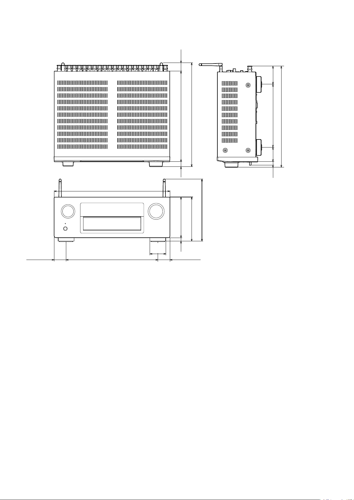
DIMENSION
Unit : in. (mm)
Weight : 31 lb 1 oz (14.1 kg)
(32)
1 3/8
13 3/8 (339)
15 1/2 (393)
(70)
2 7/8
9 3/8 (237)
(55)
2 1/4
15 1/8 (383)
17 1/8 (434)
13 5/8 (344)
2 3/8
(60)
7/8
(22)
5/8
(15) 6 (152)
1 7/8 (45) 1 7/8 (45)
6 5/8 (167)
9 3/8 (235)
1/2
(12)
10
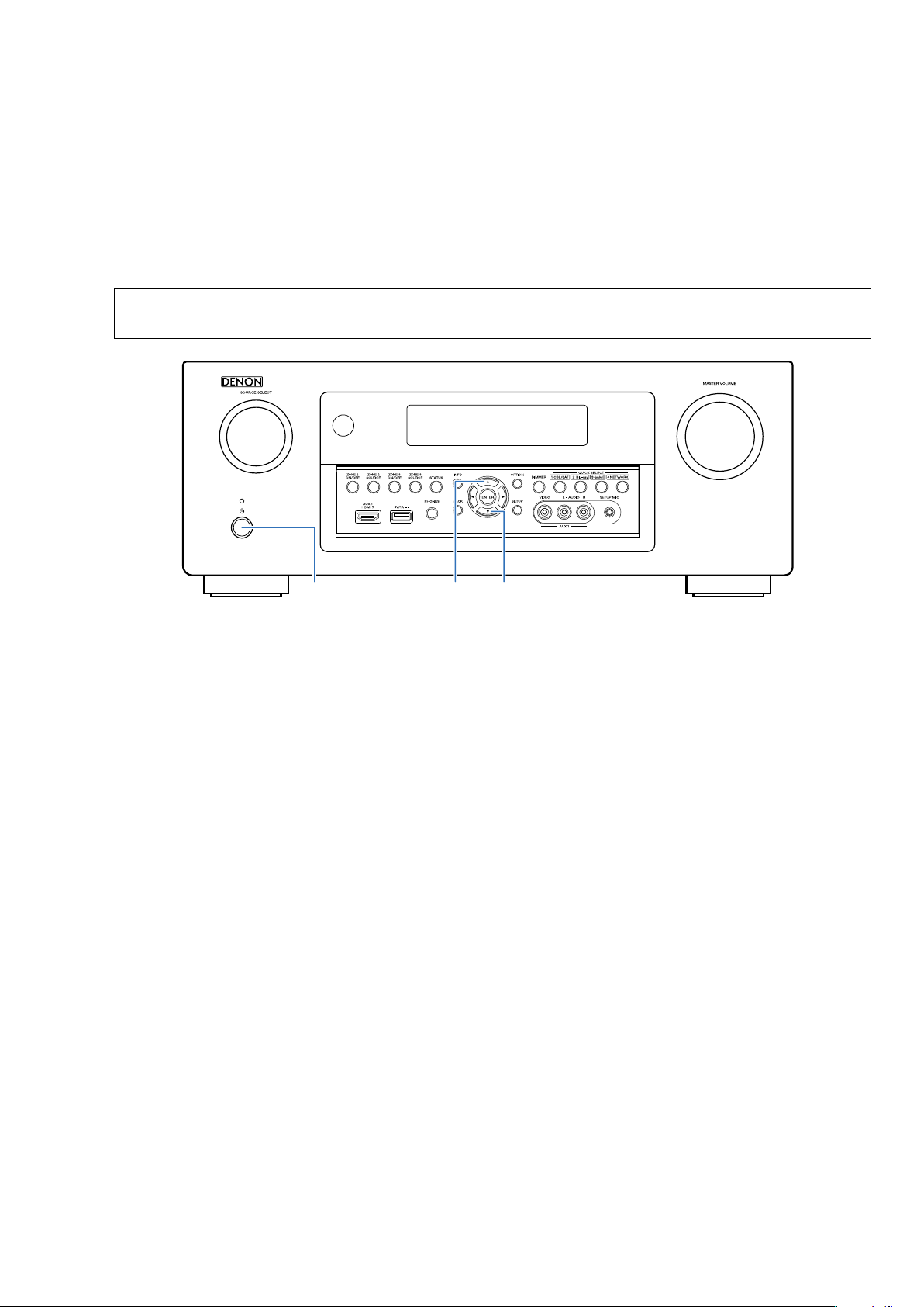
CAUTION IN SERVICING
Initializing This Unit
Make sure to initialize this unit after replacing the microcomputer or any peripheral equipment, or the digital PCB.
1. Press the power button to turn off the power.
2. While holding down buttons "
power.
3. Release the buttons after conrming that the display ashes at 1-second intervals.
* The unit is initialized.
CURSOR
d
" and "
CURSOR
" simultaneously, press the power button to turn on the
f
NOTE:
• If the unit fails to enter the service mode in step 3, repeat the procedure from step 1.
• Initializing the device restores the customized settings to the factory settings. Write down your settings in advance and
recongure the settings after initialization.
X
CURSOR d CURSOR f
JIG FOR SERVICING
Use the following jigs (extension cable kit) when repairing the PCBs.
Order with your dealer for the jigs your dealer if necessary.
8U-110084S : EXTENSION UNIT KIT : 2Sets
(See page 77)
11
DISASSEMBLY
• Remove each part following the ow below.
• Reassemble the removed parts in the reverse order.
• Read "Precautions During Work" before reassembling the removed parts.
• If wire bundles are removed or moved during adjustment or part replacement, reshape the wires after completingthe
work. Failure to shape the wires correctly may cause problems such as noise.
TOP COVER
FRONT PANEL ASSY
See "DISASSEMBLY"
1. FRONT PANEL ASSY
and "EXPLODED VIEW"
FLD PCB
(Ref. No. of EXPLODED VIEW : C1)
HP PCB
(Ref. No. of EXPLODED VIEW : C2)
HDMI USB FRONT PCB
(Ref. No. of EXPLODED VIEW : B2)
RADIATOR ASSY
See "DISASSEMBLY"
2. RADIATOR ASSY
and "EXPLODED VIEW"
AMP PCB
(Ref. No. of EXPLODED VIEW : D)
R-AMP CONNECT PCB
(Ref. No. of EXPLODED VIEW : D1)
L-AMP CONNECT PCB
(Ref. No. of EXPLODED VIEW : D2)
RADI_PROTDET2 PCB
(Ref. No. of EXPLODED VIEW : D5)
SMPS PCB
See "DISASSEMBLY"
3. SMPS PCB
and "EXPLODED VIEW"
SMPS PCB
(Ref. No. of EXPLODED VIEW : D3)
MAIN TRANS
See "DISASSEMBLY"
4. MAIN TRANS
and "EXPLODED VIEW"
POWER TRANS
(Ref. No. of EXPLODED VIEW : 8)
BACK PANEL ASSY
See "DISASSEMBLY"
5. BACK PANEL ASSY
and "EXPLODED VIEW"
DIGITAL PCB
(Ref. No. of EXPLODED VIEW : A)
AUDIO/VIDEO PCB
(Ref. No. of EXPLODED VIEW : B)
DAC PCB
(Ref. No. of EXPLODED VIEW : B1)
CONNECTOR-1 PCB
(Ref. No. of EXPLODED VIEW : B4)
CONNECTOR-2 PCB
(Ref. No. of EXPLODED VIEW : B5)
CONNECTOR-3 PCB
(Ref. No. of EXPLODED VIEW : B6)
CONNECTOR-5 PCB
(Ref. No. of EXPLODED VIEW : B8)
SPEAKER PCB
(Ref. No. of EXPLODED VIEW : C)
HL SPEAKER PCB
(Ref. No. of EXPLODED VIEW : C3)
232C POHNO PCB
(Ref. No. of EXPLODED VIEW : D4)
12
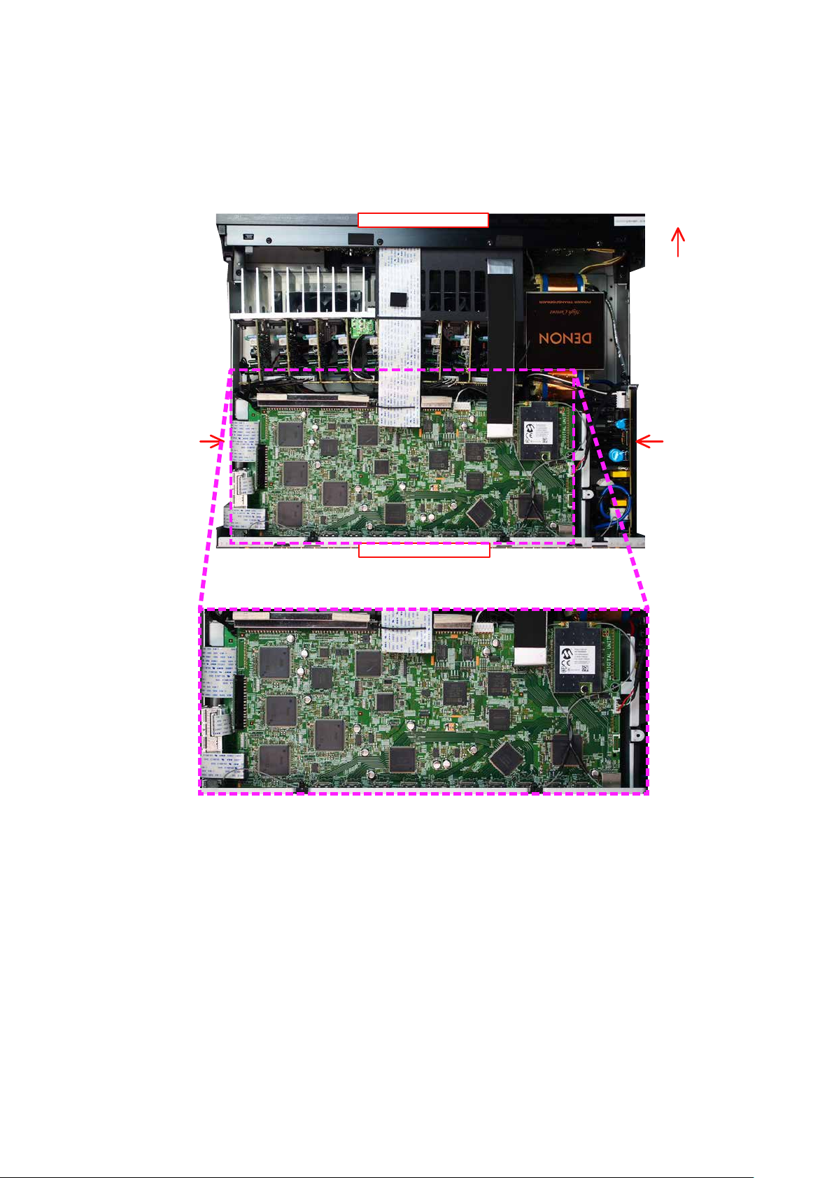
Explanatory Photos for DISASSEMBLY
• For the shooting direction of each photos used in this manual, see the photo below.
• A, B, C and D in the photo below indicate the shooting directions of photos.
• The photographs with no shooting direction indicated were taken from the top of the unit.
• Photos of AVR-X6200W E3 are used in this manual.
The viewpoint of each photograph
(Shooting direction : X) [View from the top]
↓Shooting direction: B↓
Front side
Shooting
direction: D
Shooting
direction: C
↑Shooting direction: A↑
13
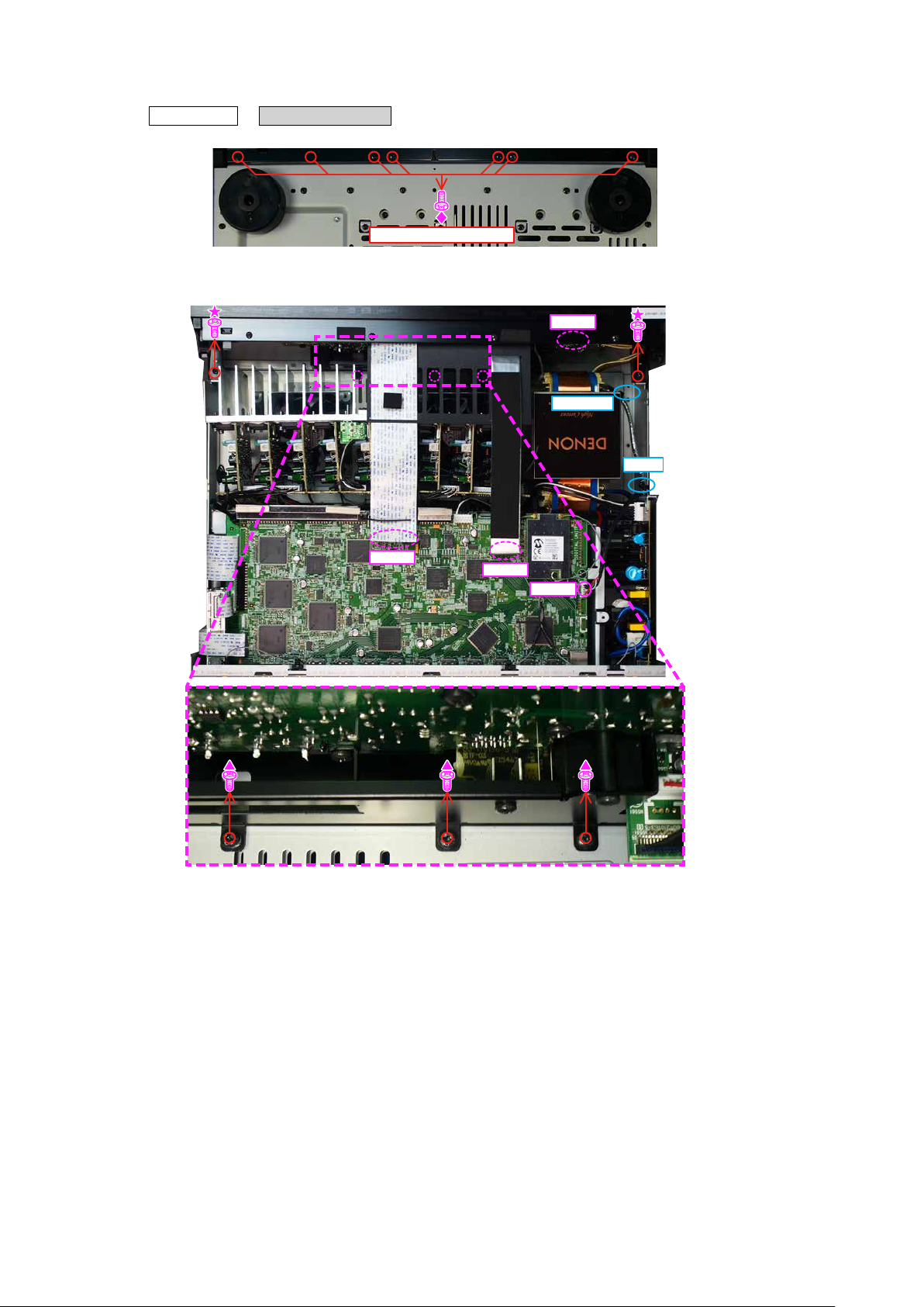
1. FRONT PANEL ASSY
Proceeding : TOP COVER
(1) Remove the screws.
(2) Remove the screws. Remove the STYLE PIN, HOLDER, FFC and connector wire.
FRONT PANEL ASSY
→
View from the bottom
N6401
HOLDER
CUT
FFC
FFC
N903
14

2. RADIATOR ASSY
Proceeding : TOP COVER
(1) Remove the STYLE PIN and connector wire. Remove the screws.
N5812 N5842
FRONT PANEL ASSY→RADIATOR ASSY
→
STYLE PIN
N5832 N5831
(2) Remove the connector wire.
FHL
SBL
YELLOW
L-AMP CONNECT R-AMP CONNECT
L-AMP CONNECT R-AMP CONNECT
SL
GRAY
C
BROWN
BLUE
FL
RED
FR
RED
SR
BROWN
SBR
FHR
GRAY
YELLOW
N5824N5814
STYLE PIN
15
N5842
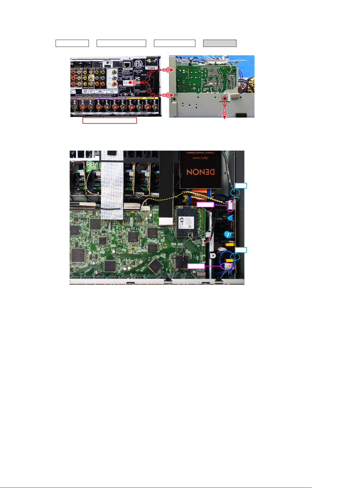
3. SMPS ASSY
Proceeding : TOP COVER
(1) Remove the screws.
FRONT PANEL ASSY→RADIATOR ASSY
→
SMPS ASSY
→
↑Shooting direction: A↑
(2) Cut the wire clamp, then remove the connector wires.
Shooting
direction: C
CUT
N6502
CUT
N6501
16
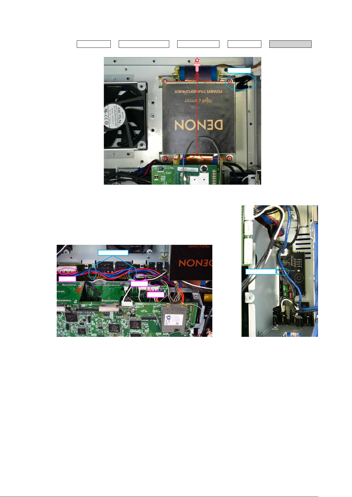
4. POWER TRANS
Proceeding : TOP COVER
(1) Remove the screws. Remove the HOLDER.
(2) Remove the STYLE PIN and connector wire.
FRONT PANEL ASSY→RADIATOR ASSY
→
SMPS ASSY
→
HOLDER
POWER TRANS
→
N6012
STYLE PIN
STYLE PIN
N6201
N9022
17
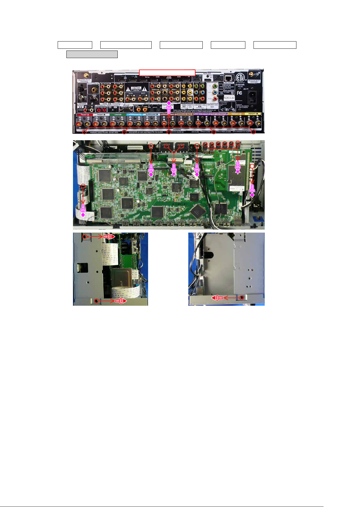
5. BACK PANEL ASSY
Proceeding : TOP COVER
BACK PANEL ASSY
→
(1) Remove the screws.
FRONT PANEL ASSY→RADIATOR ASSY
→
↑Shooting direction: A↑
SMPS ASSY
→
POWER TRANS
→
Shooting
direction: D
Shooting
direction: C
18
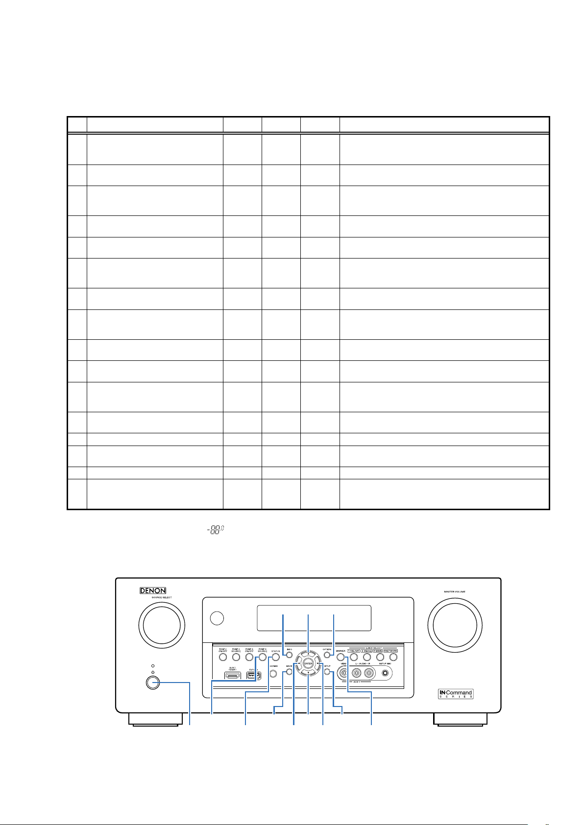
SPECIAL MODE
Special mode setting button
No. 1 - 6, 9 : While holding down buttons "A", "B" and "C" simultaneously, press the power button to turn on the power.
b
No. 7, 8 : While the power is on, hold down buttons "A" and "B" for at least 3 seconds .
b
No. 10 : While holding down buttons "A" and "B" simultaneously, insert the AC plug into the wall outlet to turn on the power.
b
No. Mode Button A Button B Button C Descriptions
Version Display
1
(u-COM / DSP Error Display)
2 Selecting the Mode for Service-related STATUS
2-1 Check the Video/Audio path Mode ↑ - -
2-2 Protection history display mode ↑ - -
2-3 232C Standby Clear Mode ↑
2-4 Operation Info Mode ↑ - -
TUNER STEP Mode
2-5
(E3 and E2 model only)
2-6 Remote ID Setup Mode ↑ - -
3 User Initialization Mode BACK INFO -
4 Factory Initialization Mode CURSOR dCURSOR
5 PANEL / REMOTE LOCK Selection Mode STATUS INFO -
6 Protection Pass Mode
7 CY920 Reboot Mode DIMMER SETUP - The CY920 is restarted after CY920 hang up.
CY920 Initialization Mode DIMMER
8
9 USB Update mode STATUS OPTION - Switches this unit to USB Update mode.
10 Forced USB All Device Write Mode STATUS OPTION -
SETUP OPTION -
ZONE3
SOURCE
↑ - -
f
CURSOR
0
STATUS
CURSOR
1
SOURCE
ZONE3
Displays the version of rmware such as the main rmware or DSP.
Errors that have occurred are displayed.
(See page 20)
This is a display for turning on each service-related mode.
Service-related modes: No. 2-1 - No. 2-6
This is a special mode for service conrmation used during repair
work to simplify the conrmation work for the Audio channel /
video channel. (See page 26)
Displays the protection occurrence history.
(See page 69)
Switches from 232C standby mode to normal standby mode.
(See page 70)
Displays the accumulated operating time of the unit, the
number of times the power was switched on, and the number of
occurrences of each protection. (See page 71)
Enables reception STEP of the ANALOG TUNER to be changed.
(See page 72)
If there are multiple DENON AV receivers in the same area,
this mode prevents other AV receivers from being operated
concurrently with this device. (See page 73)
Initializes backup data.
(Settings for the Installer Setup are not initialized.)
Initializes backup data.
(The settings for the Installer Setup is also initialized.)
Start this unit in the PANEL/REMOTE LOCK selection mode so that
PANEL LOCK and Remote Lock can be switched between ON and
OFF. (See page 74)
Enables the power to be turned on when protection detection is
disabled. (See page 75)
Enter this mode only after replacing Flash for CY920 and rewriting
the rmware.
Mode used when this unit cannot be recovered.
Forcibly switches this unit to USB update mode.
(See page 82)
NOTE:
When the volume indicator displays "
In this case, RS-232C communication cannot be used.
To cancel this special mode, press and hold the "
indicator returns to the normal display, RS-232C communication can be used.
SOURCE
X
", the set has entered a special mode for developers.
CURSOR
INFO OPTION
ZONE3
STATUS DIMMER
"and "
f
0 1
STATUS
" buttons for 3 seconds and longer. When the volume
d
SETUPBACK
f
19
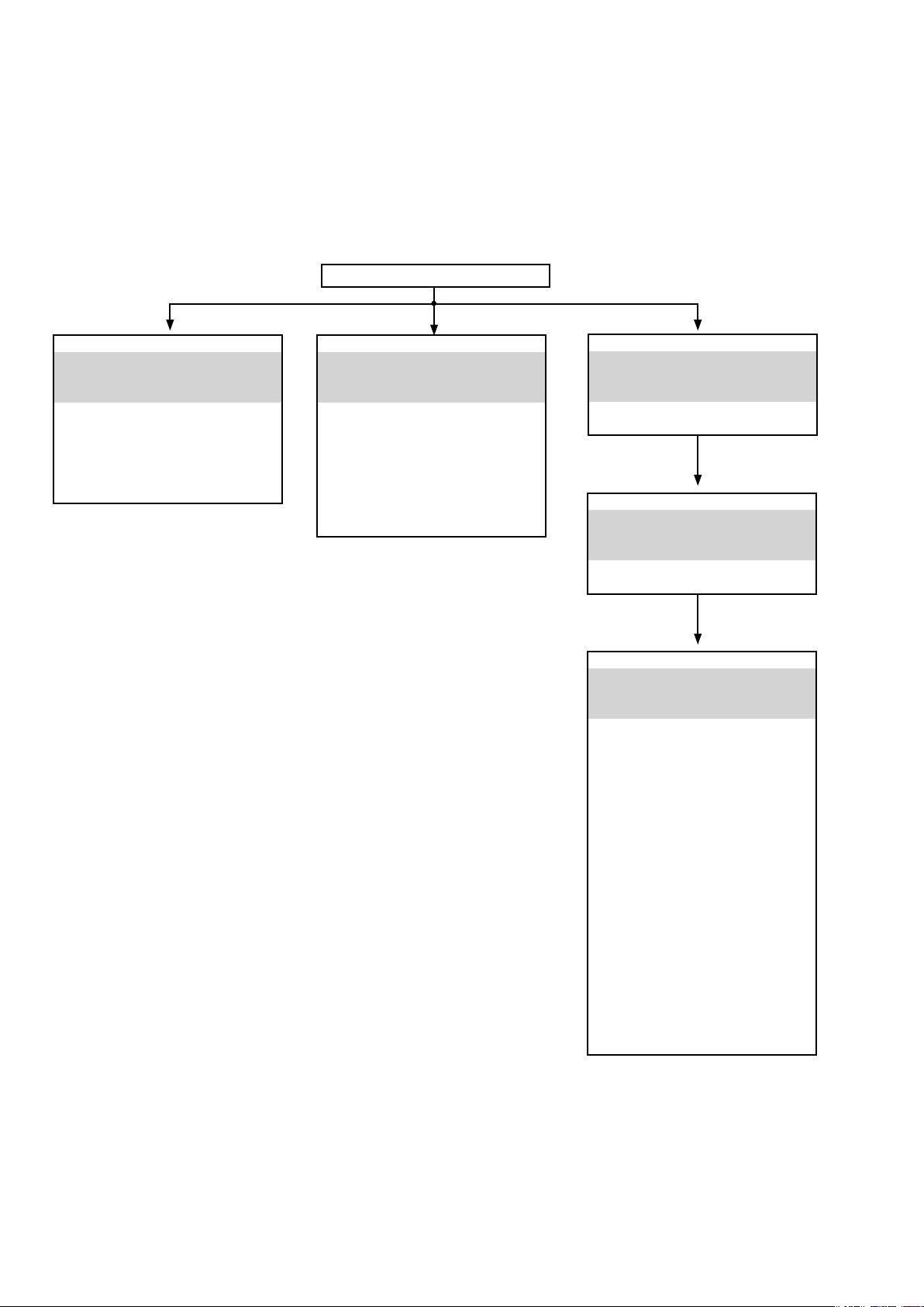
1. Version Display Mode
1.1. Actions
Version information is displayed when the device is started in this mode.
1.2. Starting up
While holding down buttons "SETUP" and "
then press the "STATUS" button to display the information in section 1.3 on the display.
The version list is also displayed on GUI while the version is displayed on the display.
b
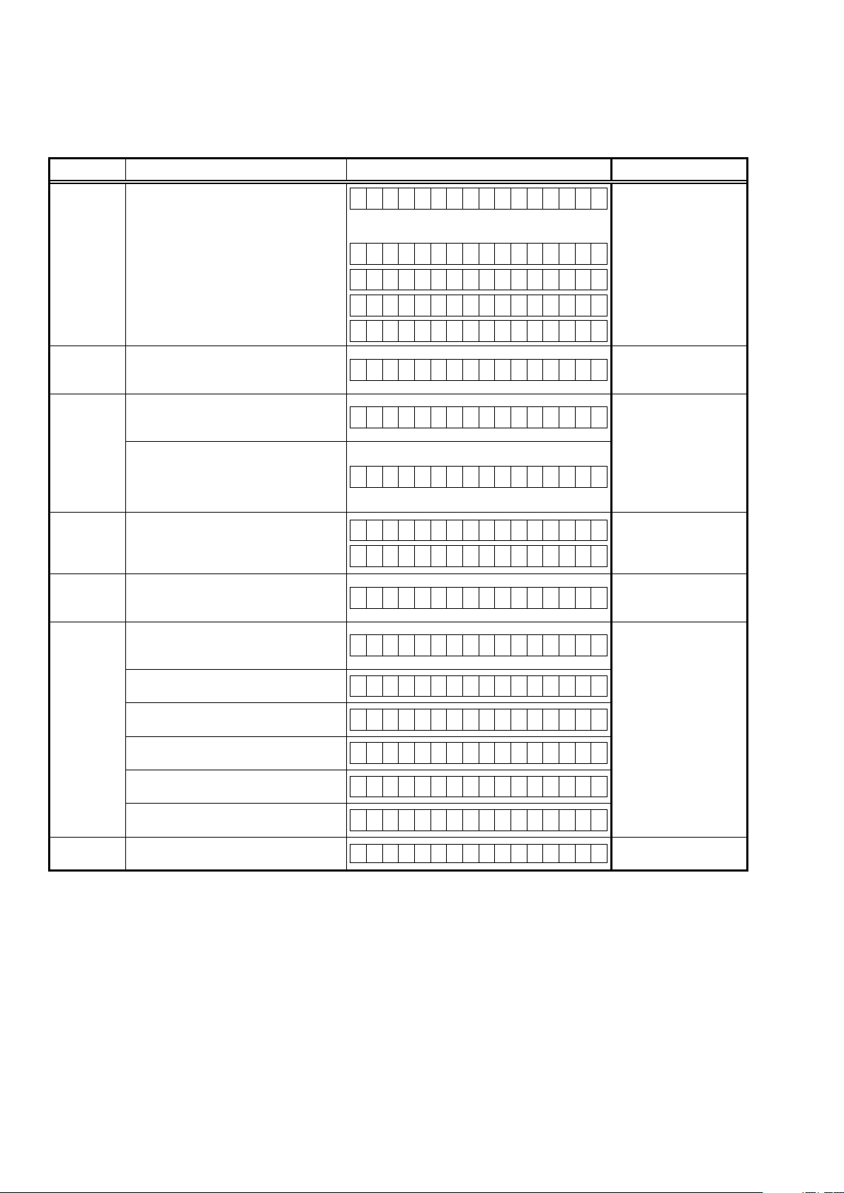
1.3. Display Order
Error information("See "1.4. Error display") → q Model destination information, Serial Number
→ w Firmware Package Version → e Main µ-com, Main 1st Boot Loader Version
→ r Sub μ -com, Sub 1st Boot Loader Version →t DSP1/2/3/4 ROM → y Audio, Video PLD → u GUI SFLASH
→ i Ethernet 1st Boot Loader, Hardware ID → o Ethernet 2nd Boot Loader, Rhapsody Flag → Q0 Ethernet IMAGE
→ Q1 Ethernet MAC ADDRESS information → Q2 BT MAC ADDRESS information → Q3 HD Radio (E3 only)
→ Q4 MultEQ Pro APP (Displayed when Audyssey Pro is complete)
→ Q5 MultEQ Pro ICL (Displayed when Audyssey Pro is complete)
Model destination information, Serial Number:
q
FLD L1
A V R - X 6 2 0 0 W E 3
OPTION
" simultaneously, press the power button to turn on the power.
FLD L1
FLD L1
FLD L2
Firmware Package Version:
w
FLD
Main µ-com, Main 1st Boot Loader Version:
e
FLD
Sub µ-com, Sub 1st Boot Loader Version:
r
FLD
DSP1/2/3/4 ROM :
t
FLD
A V R - X 6 2 0 0 W E 2
A V R - X 6 2 0 0 W E 1 C
S / N . * * * * * * * * * *
L1
L2
L1
L2
L1
L2
L1
L2
F i r m . P a c k a g e
M a i n : * * . * *
M a i n F B L : * * . * *
S u b : 7 1 1 0 * * * *
S u b F B L : * * . * *
D S P 1 : * * . * *
D S P 2 : * * . * *
V e r . : * * * *
L1
FLD
L2
Audio, Video PLD :
y
L1
FLD
L2
D S P 3 : * * . * *
D S P 4 : * * . * *
A u d i o P L D : * * . * *
V i d e o P L D : * * . * *
20
GUI SFLASH :
u
FLD L1
Ethernet 1st Boot Loader, Hardware ID :
i
L1
FLD
L2
Ethernet 2nd Boot Loader, Rhapsody Flag :
o
L1
FLD
L2
Ethernet IMAGE :
Q0
L1
FLD
L2
Ethernet MAC ADDRESS information:
Q1
L1
FLD
L2
G U I : 7 0 1 Z * * * *
Z
: Region code (E3=1, E2=2, E1C=5)
E t h e r n e t F B L
* * * * * * - A A
AA
: Hardware ID
E t h e r n e t S B L
* * * * * * * * * * * * * - B B
BB
: Rhapsody Flag
E t h e r n e t I M G
* * * * * * * * * * * * *
* N E T M A C A d d r e s s
* * * * * * - * * * * * *
BT MAC ADDRESS information:
Q2
L1
FLD
HD Radio :
Q3
FLD
S
: Software Congration, R : Release Type, V : Base Version No., B : Build No.
MultEQ Pro APP :
Q4
FLD
MultEQ Pro ICL :
Q5
FLD
* B T M A C A d d r e s s
L2
L1
L2
L1
L2
L1
L2
* * * * * * - * * * * * S
* H D : S S S S S S S S -
R V V V V . B B B
* M u l t E Q P r o A P P
* * . * * . * * . * * * *
* M u l t E Q P r o I C L
* * . * * . * * . * * * *
21
1.4. Error display
See the table below for descriptions of the displayed errors and countermeasures for these.
If multiple errors occur, only one item is displayed.
The priority order is w, e, r, y, u, q.
Condition States Display TROUBLE SHOOTING
The model name, brand name and region
information written in the rmware
are compared to the region settings in
q
Firm Check
NG
w
Sub μ -COM NGThere is not a reply from SUBμ-COM.
e
IP SCALER NG
r
GUI Serial
Flash NG
t
DIR NG
y
DSP* NG
(*:1/2/3/4)
u
EEPROM NG
the PCB. This error is displayed if the
information does not match.
" ▲ " is displayed as the rst character
if the rmware is not correct (see the
illustrations on the right).
An error occurs in Loopback Test of the
DDR memory which is performed during
the initial setting of i/p Scaler (ADV8003).
During the initial setting of i/p Scaler (
ADV8003 ) , there is not the reply of the
Loopback Test result of the DDR memory .
If the Main CPU version is not supported
by the GUI Serial Flash (ADV8003),
" ▼ " is displayed as the rst character of
the GUI rmware version.
This error is displayed if there is no
response from the DIR.
The DSP* FLAG0 port does not enter "Hi"
status while booting a DSP code even
after resetting DSP.
The DSP* FLAG0 port does not enter "Hi"
status before issuing a DSP command.
Setting WRITE to "Lo" does not set ACK to
"Hi" during DSP* data reading.
Setting REQ to "Lo" does not set ACK to
"Lo" during DSP* data reading.
Setting WRITE to "Hi" does not set ACK to
"Hi" during DSP* data writing.
Setting REQ to "Lo" does not set ACK to
"Lo" during DSP* data writing.
An error occurred in a checksum of the
EEPROM(*** is a block address number).
F I R M E R R O R
–
M a i n : * * . * *
–
D S P 1 : * * . * *
–
A u d i o P L D : * * . * *
–
G U I : * * * * * * * *
S U B E R R O R 0 1
I P S C A L E R E R R 0 1
I P S C A L E R E R R 0 2
G U I V E R . E R R O R
•
G U I : * * * * * * * *
D I R E R R O R 0 1
D S P * E R R O R 0 1
D S P * E R R O R 0 2
D S P * E R R O R 0 3
D S P * E R R O R 0 4
D S P * E R R O R 0 5
D S P * E R R O R 0 6
E 2 P R O M E R R * * *
• Check the resistor for
setting region(R5003,
R5004, R5006, R5007,
R5013, R5014 DIGITAL
PCB).
• Write the rmware for
the correct region.
• Check the SUB(U2101)
and surrounding circuits.
• Check the circuits
around the IP SCALER
(U2800, DIGITAL PCB)
and DDR2 (U3000/
U3001).
If there appear to be
no problems, U2800 or
U3000/U3001 is faulty.
• Check the rmware
version.
• Check the DIR (U1000,
DIGITAL PCB) and
surrounding circuits.
• Check the DSP (U101,
U201, U301, U401,
DIGITAL PCB) and
surrounding circuits.
22
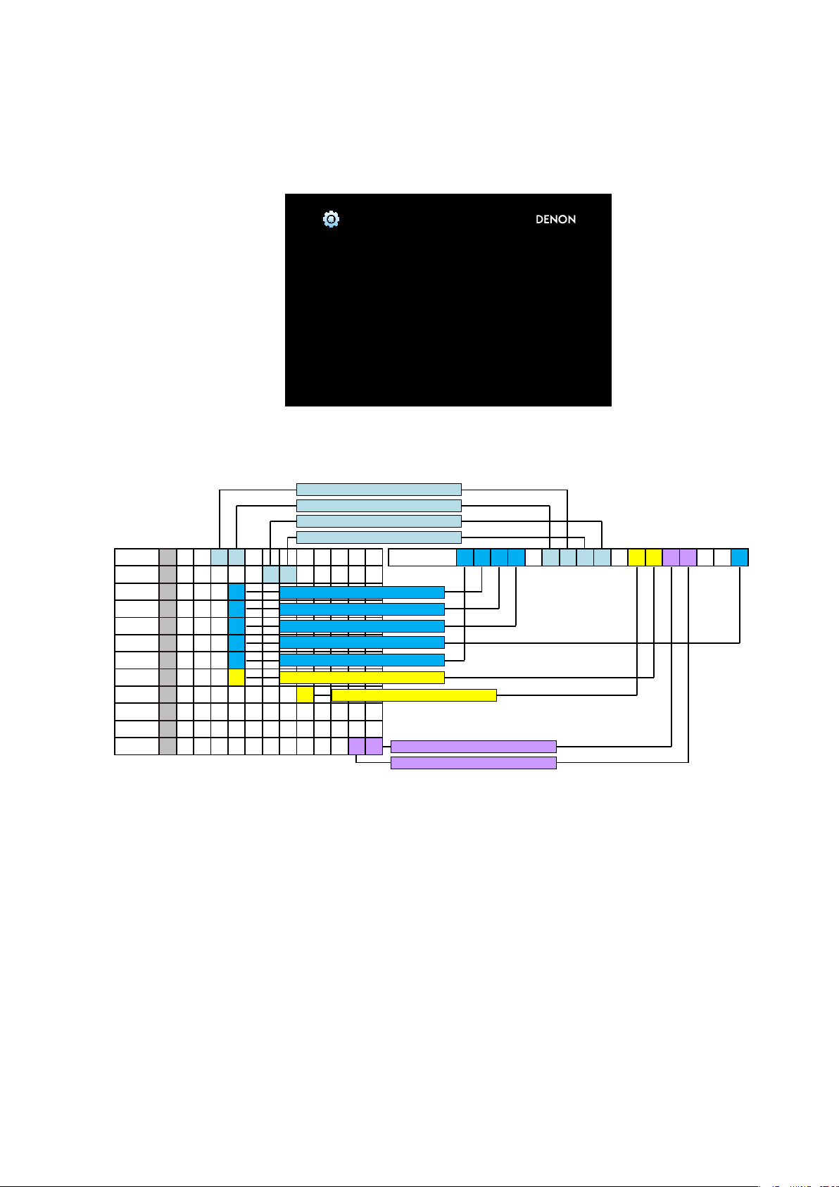
1.5. Version Display in the Setup Menu
Follow the steps below to display the rmware information.
SETUP
(1) Press the "
(2) Select "General - Information - Firmware".
The version information is displayed as a 14-digit number as shown in the screenshot below.
This 14-digit number comprises a part of the version number of each device and module.
These version numbers correspond to the 14-digit number as shown below.
Main
Sub
DSP1
DSP2
DSP3
DSP4
A.PLD
V.PLD
GUI
E.FBL
E.SBL
E.IMG
X
X X X 0 0 2 8
X X X
X X X
X X X
X X X
X X X
X X X
X X X X 0 0 1 6
X X X X X X
XB X X X X X X X X X X X
XI X X X X X X X 0 0 3 7
" button on the remote control.
General/Firmware
Version
GUI Image
The 2nd digit from the right for Main
The 1th digit from the right for Main
The 2nd digit from the right for Sub
The 1st digit from the right for Sub
8X 3 8- 3 8 21
2
3
4
5
1
7
The 1st digit from the right for DSP1
The 1st digit from the right for DSP2
The 1st digit from the right for DSP3
The 1st digit from the right for DSP4
The 1st digit from the right for A.PLD
The 1st digit from the right for V.PLD
The 1st digit from the right for GUI
XXXX - XXXX - XXXX - XX
Info display 2 3 4 - 6 7 7 3 - 0 5
The 1st digit from the right for IMG
The 2nd digit from the right for IMG
The rmware version numbers and this 14-digit version information are written in the Service Information.
b
23
2. Selecting the Mode for Service-related Operations
2.1. Actions
Select diagnostic mode (service path check mode), protection history display mode, or 232C standby clear mode.
2.2. Starting up
While holding down buttons "
power.
Select the desired mode using the "
STATUS
CURSOR f/
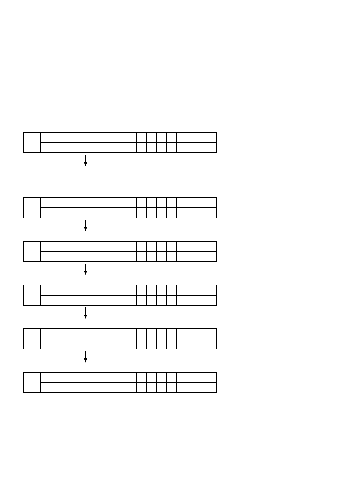
2.3. Displaying and Selecting Each Mode
The information shown on the display switches each time the "
Press the "
q
FLD
Service Path Check Mode:
The Video and Audio paths can be checked.
This function is convenient for conrming problem paths in the product and checking
w
FLD
The protection history can be checked.
ENTER
L1
L2
L1
L2
" button to set the currently displayed mode and restart the device.
– 1 . S E R V I C E C H E C K
2 . P R O T E C T I O N
the paths after repairing.
1 . S E R V I C E C H E C K
– 2 . P R O T E C T I O N
ZONE3 SOURCE
" and "
" simultaneously, press the power button to turn on the
" button, then press the "
d
CURSOR f/
ENTER
" button to conrm.
" button is pressed.
d
e
L1
FLD
L2
Switches from 232C standby mode to normal standby mode.
r
L1
FLD
L2
Operation Info for the unit can be checked.
t
L1
FLD
L2
Enables reception STEP of the ANALOG TUNER to be changed.
y
L1
FLD
L2
This function is for operating only the desired AV receiver.
2 . P R O T E C T I O N
– 3 . R S 2 3 2 C R E S E T
3 . R S 2 3 2 C R E S E T
– 4 . O P I N F O
4 . O P I N F O
– 5 . T U N E R F R Q S E T
5 . T U N E R F R Q S E T
– 6 . R E M O T E I D
2.3. Canceling the selected mode
Press the power button to turn off the power.
24
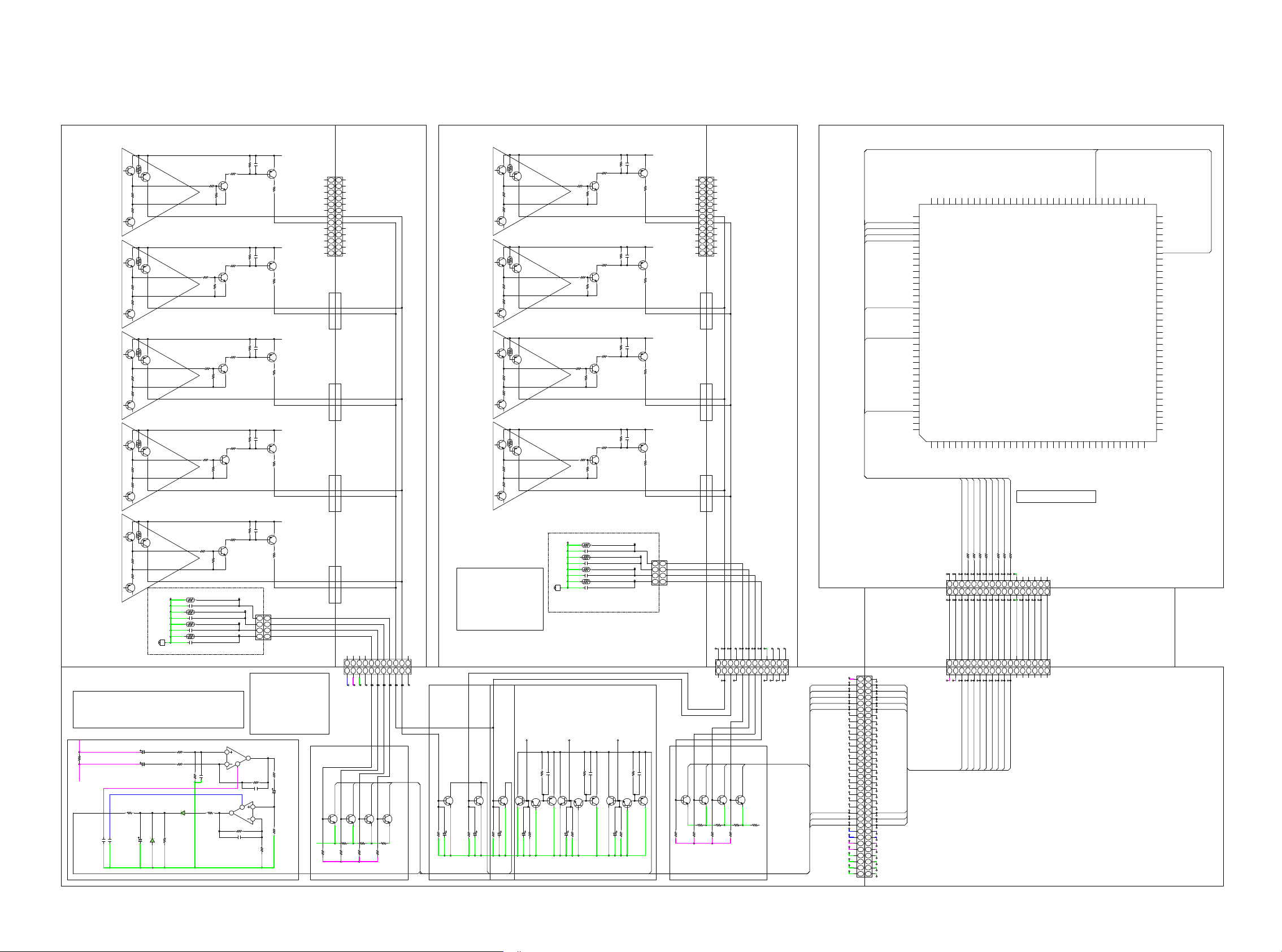
PROTECTIONDIAGRAM
AVR-X6200 ASO/DC/THERMAL PROTECTION DIAGRAM
8U-110157-1 P.AMP UNIT
TR Thermal
FL
TR Thermal
C
TR Thermal
SL
TR Thermal
ASO
ASO
ASO
ASO
N101
13P-SOCKET(C125Z2)
+B
TR_THERMAL_A
ASODET
+B
TR_THERMAL_A
ASODET
8U-110157-5 L AMP CONNECT UNIT
N5801
13P-PLUG(C125Z1)
13
13
12
12
11
11
10
10
9
9
8
8
7
7
6
6
5
5
4
4
3
3
2
2
1
1
(P=1.9mm)
+B
TR_THERMAL_A
ASODET
+B
8U-110157-1 P.AMP UNIT
TR Thermal
FR
TR Thermal
SR
TR Thermal
SBR
TR Thermal
ASO
ASO
ASO
ASO
N101
13P-SOCKET(C125Z2)
+B
TR_THERMAL_B
ASODET
+B
TR_THERMAL_B
ASODET
8U-110157-5 R AMP CONNECT UNIT
N5805
13P-PLUG(C125Z1)
13
13
12
12
11
11
10
10
9
9
8
8
7
7
6
6
5
5
4
4
3
3
2
2
1
1
(P=1.9mm)
+B
TR_THERMAL_B
ASODET
+B
8U-310202 DIGITAL UNIT
101
102
103
104
105
106
107
FANDET_HIGH
FANDET_ON
ASODET
DCDET
TRDET
AMPSIGDET
CURRENTDET
108
PE1
PE0
109
PD7
110
PD6
111
PD5
112
PD4
113
P64
114
P63
115
P62
116
P61
117
P60
118
PD3
119
PD2
120
PD1
121
PD0
122
P97
123
P96
124
P95
125
P94
126
P93
127
P92
128
P91
129
VSS
130
P90
131
VCC
132
P47
133
P46
134
P45
135
P44
136
P43
137
P42
138
P41
139
VREFL
140
P40
141
VREFH
142
AVCC
143
P05
144
P042P033P674P665AVSS6P027P018P009P6510EMLE11WDTOVF#12VSS13MDE14VCL15MD116MD017P8618P8519RES#20XTAL21VSS22EXTAL23VCC24NMI25P3426P3327P3228P3129P3030P2731P2632P2533P2434P2335P2236P21
1
PE2
PE3
PE6
PE5
PE4
NC
SWM3.3V
PE7
100
PA1
PA0
U5001
R5F56108VNFP
THERMALINF
P81
P36
P37
P10
P11
73
PC374VCC75PC276VSS77PC178PC079PB780PB681PB582PB483PB384PB285PB186P7487P7388P7289P7190P7091VCC92PB093VSS94PA795PA696PA597PA498PA399PA2
PC4
PC5
PC6
PC7
P75
P76
P77
P50
P51
P52
BCLK
P80
VCC
P82
VSS
P83
P54
P55
P56
P57
P84
P35
P12
P13
P14
P15
PLLVSS
P16
PLLVCC
P17
P20
72
71
70
69
68
67
THERMALINE
66
65
64
63
62
61
60
59
58
57
56
55
54
53
52
51
50
49
48
47
46
45
44
43
42
41
40
39
38
37
SBL
TR_THERMAL_A
ASODET
TR Thermal
ASO
+B
FHWL
TR_THERMAL_A
TPF296
Z5801
TPF294
Radiator
Thermal
M3-SIDE
PRF18BB471QB5RB
C5801
4.7u
Z5802
PRF18BB471QB5RB
C5802
4.7u
Z5803
PRF18BF471QB5RB
C5803
4.7u
Z5804
PRF18BF471QB5RB
4.7u
C5804
B5801
8U-110156-1 SPK UNIT
CURRENT DETECTION THRESHOLD
16.3Arms(7.3Adc) -> Shut down
5.6Arms (2.5Adc) -> Fans highly operate , Change +B voltage
3.9Arms (1.8Adc) -> Fans operate
1/100
+B
5W
0.01
R6060
V load
Current
Detection
0.1
C6021
0.1
C6022
C6023
C6024
R6079
1608
33K
C6025
KR3
1/100
KR3
A+7V.
100/16
KR3
R6081
R6082
UDZS3.6B
10K
1608
D6023
R6083
10K
10K
R6084
10K
D6025
KDS160
C6026
OPEN
R6087
3.3K
1608
N5816
4P-PH-SAN
80mm
TPF297
1
TPF298
2
3
TPF299
4
PROTECTION LOGIC
DCDET :L -> Shut down
ASODET :L -> Shut down
TRDET :L -> HiB -> LoB
ThermalDET :L -> Shut down
FANDET_ON :L -> Fans operate
FANDET_HIGH :L -> Fans
highly operate
5
7
8
U6001
6
NJM8080G
R6089
10K
C6063
OPEN
1608
U6001
NJM8080G
3
4
1
2
R6088
330K
C6062
OPEN
1608
10K
R6090
CURRENTDET
ASODET
RADI_PROTDET_E
1
RADI_PROTDET_F
2
FANDET_ON
3
FANDET_HIGH
4
N5815
4P-PHs
1K
R6091
KR3
1/100
C6027
33K
R6092
Radiator
Thermal
FANDET_HIGH
FAN+B
AMPGND
FANGND
1
2345678
1
2345678
N6010
11P-PH
TPF44
TPF46
TPF45
AMPGND
FANDET_HIGH
FAN+12V-1
FANGND
B11B-PH-K-S(LF)(SN)
FANDET_ON
FANDET_HIGH
KTC3875S
KTC3875S
Q6001
Q6003
0
R6005
R6009
R6003
R6001
82K
1608
R6007
82K
220K
1608
1608
RLYB+12V
RADI_PROTDET_F
RADI_PROTDET_E
FANDET_ON
TR_THERMAL_A
-FILTB
ASODET
9
10
9
10
TPF41
TPF40
TPF43
TPF39
TPF42
TPF38
THERMALDET_E
-FILTB
THERMALDET_F
ASODET
FANDET_ON
TR_THERMAL_A
THERMALDET_F
THERMALDET_E
KTC3875S
KTC3875S
Q6006
Q6008
0
R6014
0
R6012
220K
1608
FHWL
N5812
11P-PHs
11
S11B-PH-K-S(LF)(SN)
11
TPF36
TPF37
TR Thermal
KTC3875S
Q6010
10K
10/63
1608
KR3
R6018
C6004
Radiator
Thermal
TPF295
TEMPERATURE THRESHOLD
RADIATOR
125 degree -> Shut down
105 degree -> Fans highly operate
75 degree -> Fans operate
POWER TR
100 degree -> Change +B Voltage
DC
ASO
PRF18BB471QB5RB
Z5805
C5805
4.7u
Z5806
PRF18BB471QB5RB
C5806
4.7u
Z5807
PRF18BF471QB5RB
C5807
4.7u
Z5808
PRF18BF471QB5RB
C5808
4.7u
B5802
M3-SIDE
From Power Amp Output
0.1
100K
1608
1608
KTA1504S
C6008
R6032
Q6015
Q6014
KTC3875S
KR3
SR ch
SL ch
SBR ch
0.1
100K
1608
1608
KTC3875S
C6010
R6040
Q6016
Q6017
330/10
KTC3875S
15K
1608
C6009
R6038
KTA1504S
Q6018
KTC3875S
Q6011
10K
10/63
1608
KR3
R6019
C6005
3.3K
47/25
1608
KR3
C6006
R6020
TRDET
FR ch
FL ch
C ch
KTC3875S
KTC3875S
Q6012
Q6013
330/10
15K
1608
KR3
C6007
R6022
ASODET
TPF300
N5826
4P-PH-SAN
80mm
TPF301
1
TPF302
2
3
TPF303
FANDET_ON
0.1
100K
1608
1608
C6016
R6055
Q6020
KTC3875S
4
KTA1504S
Q6021
RADI_PROTDET_E
RADI_PROTDET_F
FANDET_HIGH
SBL ch
FHWR ch
FHWL ch
KTC3875S
Q6019
330/10
15K
1608
KR3
C6013
R6050
DCDET
TR_THERMAL_B
ASODET
RADI_PROTDET_E
1
RADI_PROTDET_F
2
FANDET_ON
3
FANDET_HIGH
4
N5825
4P-PHs
FANDET_HIGH
OPEN
Q6002
OPEN
OPEN
R6004
R6002
RLYB+12V
Radiator
Thermal
ASODET
TR_THERMAL_B
1
2
N5822
12P-PHs
1
2
N6011
12P-PH
ASODET
S12B-PH-K-S(LF)(SN)
TR_THERMAL_B
FANDET_ON
THERMALDET_F
OPEN
OPEN
Q6004
Q6007
R6010
R6006
OPEN
OPEN
OPEN
R6008
R6013
AMPGND
FANDET_ON
-FILTB
RADI_PROTDET_F
RADI_PROTDET_E
FANDET_HIGH
FAN+12V
9876543
10
9876543
10
-FILTB
AMPGND
FAN+12V
FANDET_ON
FANDET_HIGH
THERMALDET_F
THERMALDET_E
THERMALDET_E
OPEN
Q6009
R6015
R6017
OPEN
OPEN
OPEN
FANGND
11
12
11
12
FANGND
N6013
SWM3.3V
33P-FFC
CURRENTDET
TEHRMALDET_E
THERMALDET_F
FANDET_ON
FANDET_HIGH
BRL_HIGH
FANCONT_ON2
FANCONT_L_ON2
FANCONT_ON1
FANCONT_L_ON1
SPRL_F
SPRL_C
SPRL_S
SPRL_SB
SPRL_F_SB
SPRL_F_W
SPRL_W_SB
SPRL_W
SPRL_SB_W
SPRL_W_H
AMPSIGDET
TRDET
DCDET
ASODET
A-7V
A-7V
A+7V
A+7V
DGND
DGND
PREPOWERGND
PREPOWERGND
8U-210163-3
CONNECT-1_UNIT
33
1
CURRENTDET
32
2
THERMALDET_E
31
3
-
30
4
FANDET_ON
29
5
FANDET_HIGH
28
6
27
7
26
8
25
9
24
10
23
11
22
12
21
13
20
14
19
15
18
16
17
17
16
18
15
19
14
20
13
21
12
22
TRDET
11
23
DCDET
10
24
ASODET
9
25
8
26
7
27
6
28
5
29
4
30
3
31
2
32
1
33
33P-FFCs
-
N3003
TRDET
DCDET
ASODET
<- Pulled down by 1Mohms
AMPSIGDET
FANDET_ON
THERMALINE
THERMALINF
CURRENTDET
FANDET_HIGH
R5061
R5060
R5062
R5057
R5056
1005
1005
100
100
17
17
R5059
1005
1005
100
100
11
10
1213141516
10111213141516
1005
100
9
R5063
1005
1005
100
100
1
2345678
N5003
123456789
17P-PLUG(C125Z1)
N5905
17P-SOCKET(C125Z2)
FANDET_ON
AMPSIGDET
SWM3.3V
TEHRMALE
TRIG12V
CURRENTDET
17
17
TRIG12V
SWM3.3V
TEHRMALE
CURRENTDET
CURRENTDET
THERMALDET_E
FANDET_ON
THERMALF
THERMALF
FANDET_ON
THERMALDET_F
FANDET_ON
DGND
DCDET
TRDET
ASODET
FANDET_HIGH
AMPSIGDET
10111213141516
10111213141516
DCDET
TRDET
DGND
ASODET
AMPSIGDET
FANDET_HIGH
FANDET_HIGH
AMPSIGDET
TRDET
DCDET
ASODET
DGND
AEXP_CLK
AEXP__OE
AEXP_DATA
AEXP_STB
N5906
17P-PLUG(C125Z1)
123456789
123456789
N9018
17P-SOCKET(C125Z2)
DGND
AEXPDATA
AEXP__OE
AEXP_STB
AEXP_CLK
8U-210163-1 AUDIO/VIDEO_UNIT
25
2-1DIAGNOSTICMODE(ServicePathCheckMode)
2-1.1.Actions
This function is convenient for conrming problem paths in the product and executing a path check after repair.
The Video and Audio paths can be checked.
The backup data is not rewritten.
2-1.2.Startingup
Hold down buttons "STATUS" and "ZONE3SOURCE" at the same time and press the power button to turn on the power.
Select
"1.SERVICECHECK" and press the "ENTER" button to start the diagnostic mode.
The "TUNED", "STERO" and "RDS" segments are lit in this mode.
2-1.3.Cancelingdiagnosticmode
Press the power button to turn off the power.
2-1.4.Selectingitems
Press q button to switch between video items and audio items.
Press button w or e to select the previous or next item.
The unit Remote control unit
Actions
Button DIMMER CURSOR
q w e q w e
Audio ⇔ Video PREVIOUS NEXT Audio ⇔ Video PREVIOUS NEXT
0
CURSOR
1
SLEEP CURSOR
0
CURSOR
1
2-1.5.Audiosystemconrmationitems
g. XX: See the block diagram of the g.XXth.
Pathsconrmationitem Display Settings ContentsofconrmationRemarks
Analog
(MAIN ZONE)
1
Digital
(MAIN)
2
Digital (signal) Path
(ZONE2)
3
g.01
g.02a
g.02b
g.03a
g.03b
g.03c
A 0 1 : A N A L O G P A S S
A 0 2 : D I G I T A L
A 0 3 : D I G I T A L - Z 2
Input Source : CBL/SAT
Input Mode : Analog (xed)
Amp assign : 9.1ch
Floor Layout : 5.1 & Surround Back
Height Sp : 2ch
Dolby Sp : None
Height Layout : Front Height
MAIN ZONE : ON
ZONE2 : OFF
ZONE3 : OFF
Input Source : CBL/SAT
Input Mode : Digital (xed)
Sound mode : Multi Ch Stereo
Vol. : 60.0 (-20.0dB)
Amp assign : 9.1ch
Floor Layout : 5.1 & Surround Back
Height Sp : 2ch
Dolby Sp : None
Height Layout : Front Height
Speaker Select : Floor
Speaker Cong : All Speaker = Small/Subwoofer = 2spkrs
MAIN ZONE : ON
ZONE2 : OFF
ZONE3 : OFF
Input Source : Online Music
Input Mode : Auto
Sound mode : Stereo
Amp assign : 7.1ch + ZONE2
Speaker for ZONE2 : Surround Back
Floor Layout : 5ch
Height Sp : 2ch
Dolby Sp : None
Height Layout : Front Height
MAIN ZONE : ON
ZONE2 : ON
ZONE3 : OFF
・Analog input ⇒ Speaker output (Front L/R)
・Analog input ⇒ Preout output (Front L/R)
(bAs the input source, you can switch from CBL/SAT to other ones.)
・Digital input ⇒ Speaker output (Front L/R, Center, Surround L/R, Surround Back L/R)
・Digital input ⇒ Preout output (Front L/R, Center, Subwoofer1/2, Surround L/R, Surround Back L/R)
(bAs the input source, you can switch from CBL/SAT to other ones.)
・Digital (PCM) input ⇒ Speaker output (Surround Back L/R → ZONE2 L/R)
・Digital (PCM) input ⇒ Preout output (ZONE2 L/R)
(bAs the input source, you can switch from Online Music to other ones.)
26

Pathsconrmationitem Display Settings ContentsofconrmationRemarks
Digital (signal) Path
(ZONE3)
4
HDMI
(MAIN ZONE)
5
A/D
(MAIN ZONE)
6
Amp Assign
(ZONE2)
7
Amp Assign
(ZONE3)
8
Amp Assign
(ZONE2/ZONE3-MONO)
9
g.04a
g.04b
g.05a
g.05b
g.05c
g.06a
g.06b
g.07
g.08
g.09
A 0 4 : D I G I T A L - Z 3
A 0 5 : H D M I
A 0 6 : A D
A 0 7 : A S S I G N - Z 2
A 0 8 : A S S I G N - Z 3
A 0 9 : A S S I G N - Z 3 / 3 M
Input Source : Online Music
Input Mode : Auto
Sound mode : Stereo
Amp assign : 7.1ch + ZONE3
Speaker for ZONE3 : Front Wide/Height2
Floor Layout : 5ch
Height Sp : 2ch
Dolby Sp : None
Height Layout : Front Height
MAIN ZONE : ON
ZONE2 : OFF
ZONE3 : ON
Input Source : CBL/SAT
Input Mode : HDMI (xed)
Sound mode : Stereo
Amp assign : 9.1ch
Floor Layout : 5ch & Surround Back
Height Sp : 2ch
Dolby Sp : None
Height Layout : Front Height
MAIN ZONE : ON
ZONE2 : OFF
ZONE3 : OFF
Input Source : CBL/SAT
Input Mode : Analog (xed)
Sound mode : Multi Ch Stereo
Amp assign : 9.1ch
Floor Layout : 5ch & Surround Back & Front Wide
Height Sp : 2ch
Dolby Sp : None
Height Layout : Front Height
Speaker Select : Floor
Speaker Cong : All Speaker = Small/Subwoofer = 2spkrs
MAIN ZONE : ON
ZONE2 : OFF
ZONE3 : OFF
Input Source : CBL/SAT
Input Mode : Auto
Sound mode : Stereo
Amp assign : 7.1ch + ZONE2
Speaker for ZONE2 : Surround Back
Floor Layout : 5ch
Height Sp : 2ch
Dolby Sp : None
Height Layout : Front Height
MAIN ZONE : ON
ZONE2 : ON
ZONE3 : OFF
Input Source : CBL/SAT
Input Mode : Auto
Sound mode : Stereo
Amp assign : 7.1ch + ZONE3
Speaker for ZONE3 : Front Wide/Height2
Floor Layout : 5ch
Height Sp : 2ch
Dolby Sp : None
Height Layout : Front Height
MAIN ZONE : ON
ZONE2 : OFF
ZONE3 : ON
Input Source : CBL/SAT
Input Mode : Auto
Sound mode : STEREO
Z2 Source : Source
Z3 Source : Source
Amp assign : 7.1ch + ZONE2/3
Speaker for ZONE2/3 : Height1
Floor Layout : 5ch & Surround Back & Front Wide
MAIN ZONE : ON
ZONE2 : ON
ZONE3 : ON
・Digital (PCM) input ⇒ Speaker output (Front Wide/Height2 L/R → ZONE3 L/R)
・Digital (PCM) input ⇒ Preout output (ZONE3 L/R)
(bAs the input source, you can switch from Online Music to other ones.)
・HDMI Input ⇒ Speaker output (Front L/R)
・HDMI Input ⇒ Preout output (Front L/R)
(bAs the input source, you can switch from CBL/SAT to other ones.)
・Analog input ⇒ Speaker output (Front L/R, Center, Surround L/R, Surround Back L/R, Front Wide L/R)
・ Analog input ⇒ Preout output, SW (20Hz) (Front L/R, Center, Subwoofer1/2, Surround L/R, Surround Back L/R, Front Wide L/R)
(bAs the input source, you can switch from CBL/SAT to other ones.)
・Analog input ⇒ Speaker output (Surround Back L/R → ZONE2 L/R)
・Analog input ⇒ Preout output (ZONE2 L/R)
(bAs the input source, you can switch from CBL/SAT to other ones.)
・Analog input ⇒ Speaker output (Front Wide/Height2 L/R → ZONE3 L/R)
・Analog input ⇒ Preout output (ZONE3 L/R)
(bAs the input source, you can switch from CBL/SAT to other ones.)
・Analog input ⇒ Speaker output (Height1 L → ZONE2 MONO, Height2 R → ZONE3 MONO)
・Analog input ⇒ Preout output (ZONE2 L/R → ZONE2 MONO, ZONE3 L/R → ZONE3 MONO)
(bAs the input source, you can switch from CBL/SAT to other ones.)
27
Pathsconrmationitem Display Settings ContentsofconrmationRemarks
Amp Assign
(7.1ch (Bi-Amp)
10
Front Height
11
Front Wide
12
Front Amp>>Height 1
13
Front Amp>>Front Wide
14
g.10a
g.10b
g.11a
g.11b
g.12a
g.12b
g.13a
g.13b
g.14a
g.14b
A 1 1 : A S S I G N - B i A M P
A 1 4 : F R O N T H E I G H T
A 1 5 : F R O N T W I D E
A 2 0 : F - A M P H E I G H T
A 2 1 : F - A M P W I D E
Input Source : CBL/SAT
Input Mode : Auto
Sound mode : Multi Ch Stereo
Amp assign : 7.1ch + Bi-Amp
Speaker for Bi-Amp : Surround Back
Floor Layout : 5ch
Height Sp : 2ch
Dolby Sp : None
Height Layout : Front Height
MAIN ZONE : ON
ZONE2 : OFF
ZONE3 : OFF
Input Source : CBL/SAT
Input Mode : Auto
Sound mode : Multi Ch Stereo
Amp assign : 11.1ch
Floor Layout : 5ch & Surround Back
Height Sp : 4ch
Dolby Sp : None
Height Layout : Top Front & Top Rear
Pre-out Channel = Top Rear
Speaker Select = Floor & Height
MAIN ZONE : ON
ZONE2 : OFF
ZONE3 : OFF
Input Source : CBL/SAT
Input Mode : Auto
Sound mode : Multi Ch Stereo
Vol. : 60.0 (-20.0dB)
Amp assign : 11.1ch
Floor Layout : 5ch & Front Wide
Height Sp : 4ch
Dolby Sp : None
Height Layout : Front Height & Top Middle
Pre-out channel : Top Middle
Speaker Select = Floor & Height
MAIN ZONE : ON
ZONE2 : OFF
ZONE3 : OFF
Input Source : CBL/SAT
Input Mode : Auto
Sound mode : Multi ch Stereo
Amp assign : 11.1ch
Height Speakers = 4Height Speakers
Height Layout = Top Front & Top Rear
Pre-out Channel = Front & Top Rear
Speaker Conog > Surround Back = None
Speaker Select = Floor & Height
MAIN ZONE : ON
ZONE2 : OFF
ZONE3 : OFF
Input Source : CBL/SAT
Input Mode : Auto
Sound mode : Multi ch Stereo
Amp assign : 11.1ch
Floor Layout : 5ch & Surround Back & Front Wide
Height Sp : 2ch
Dolby Sp : None
Height Layout : Front Height
Pre-out Channel : Front
Speaker Select : Front
MAIN ZONE : ON
ZONE2 : OFF
ZONE3 : OFF
・Analog input ⇒ Speaker output (Surround Back L/R → Front L/R)
(bAs the input source, you can switch from CBL/SAT to other ones.)
・Analog input ⇒ Speaker output (Height 1 L/R → Top Front L/R)
・Analog input ⇒ Preout output (Height 1 L/R → Top Front, Height 2 L/R → Top Rear)
(bAs the input source, you can switch from CBL/SAT to other ones.)
・Analog input ⇒ Speaker output (Front Wide L/R)
・Analog input ⇒ Preout output (Front Wide L/R)
(bAs the input source, you can switch from CBL/SAT to other ones.)
・Analog input ⇒ Speaker output (Height1 L/R → Top Front L/R)
・Analog input ⇒ Preout output (Height1 L/R → Top Front, Height2 → Top Rear L/R)
(bAs the input source, you can switch from CBL/SAT to other ones.)
・Analog input ⇒ Speaker output (Front Wide L/R)
(bAs the input source, you can switch from CBL/SAT to other ones.)
28
Pathsconrmationitem Display Settings ContentsofconrmationRemarks
Wide/Height Amp>>Surround Back
A 2 3 : H - A M P B A C K
g.15a
g.15b
15
2-1.6.Videosystemconrmationitems
g. XX: See the block diagram of the g.XXth.
Pathsconrmationitem Display Settings ContentsofconrmationRemarks
Analog Video
1
Video Convert
(Analog or HDMI ⇒ HDMI)
2
HDMI pass
(MAIN ZONE)
3
HDMI CEC
4
HDMI Audio
(Audio :AVR)
5
g.16
g.17
g.18
g.19
g.20a
g.20b
g.20c
V 0 1 : V I D E O P A S S
V 0 2 : V . C O N V E R T
V 0 3 : H D M I P A S S
V 0 4 : H D M I C E C
V 0 5 : H . A U D I O - A V R
Input Source : CBL/SAT
Input Mode : Auto
Sound mode : Multi ch Stereo
Amp assign : 7.1ch + ZONE2
Speakers for ZONE2 : Front Wide/Height 2
Floor Layout : 5ch & Surround Back
Height Sp : 2ch
Dolby Sp : None
Height Layout : Front Height
Speaker Select : Floor
MAIN ZONE : ON
ZONE2 : OFF
ZONE3 : OFF
Input Source : CBL/SAT
Video Convert (IP Scaler) : OFF, All sources
MAIN ZONE : ON
ZONE2 : ON
ZONE3 : OFF
Input Source : CBL/SAT
Video Convert (IP Scaler) : ON, All sources
IP Scaler : "Analog & HDMI", All sources
Resolution : "Auto", All sources
MAIN ZONE : ON
ZONE2 : OFF
ZONE3 : OFF
Input Source : CBL/SAT
Source of Video Convert (IP Scaler) : OFF, All sources
MAIN ZONE : ON
ZONE2 : OFF
ZONE3 : OFF
Input Source : CBL/SAT
HDMI Control : ON
MAIN ZONE : ON
ZONE2 : OFF
ZONE3 : OFF
Input Source : CBL/SAT
HDMI Control : OFF
HDMI Audio : AVR ( if checking the audio output from AVR )
・Analog input ⇒ Speaker output (Surround Back L/R)
(bAs the input source, you can switch from CBL/SAT to other ones.)
・Component input ⇒ Component output
(bAs the input source, you can switch from CBL/SAT to other ones.
・CVBS input ⇒ IP Scaler ⇒ HDMI output.
・Component input ⇒ IP Scaler ⇒ HDMI output.
・HDMI input ⇒ IP Scaler ⇒ HDMI output.
・ETHERNET input ⇒ IP Scaler ⇒ HDMI output.
(bThe input source can be switched to any source except CBL/SAT.)
・HDMI input ⇒ HDMI output (MAIN ZONE)
(bThe input source can be switched to any source except CBL/SAT.)
・ When the power supply of a TV is put in the standby mode, make sure that the power supply of this unit is also put in the
standby mode.
・The ARC path can also be checked (check this using the TV input source).
(bThe input source can be switched to any source except CBL/SAT.)
・HDMI input (PCM , DolbyDigital , DTS) ⇒ Speaker output.
・HDMI input (HD audio) ⇒ Speaker output.
(bThe input source can be switched to any source except CBL/SAT.)
HDMI Audio
(Audio :TV)
6
GUI
7
HDMI
(ZONE2)
8
g.21a
g.21b
g.22
g.23
V 0 6 : H . A U D I O - T V
V 0 7 : G U I M E N U O N
V 0 8 : Z O N E 2 H D M I
Input Source : CBL/SAT
HDMI Control : OFF
HDMI Audio : TV ( if checking the audio output from TV )
Input Source : CBL/SAT
Video Convert (IP Scaler) : ON, All sources
IP Scaler : "Analog & HDMI", All sources
Resolution : "AUTO", All sources
Setup Menu : ON
MAIN ZONE : ON
ZONE2 : OFF
ZONE3 : OFF
Input Source : CBL/SAT
ZONE2 Source : Source
MAIN ZONE : ON
ZONE2 : ON
ZONE3 : OFF
・HDMI input (PCM , DolbyDigital , DTS) ⇒ HDMI output (audio output from connected TV)
(bThe input source can be switched to any source except CBL/SAT.)
・GUI display ⇒ HDMI output.
(bThe input source can be switched to any source except CBL/SAT.)
・HDMI input ⇒ HDMI output (ZONE2)
(bAs the input source, you can switch from CBL/SAT to other ones.)
29
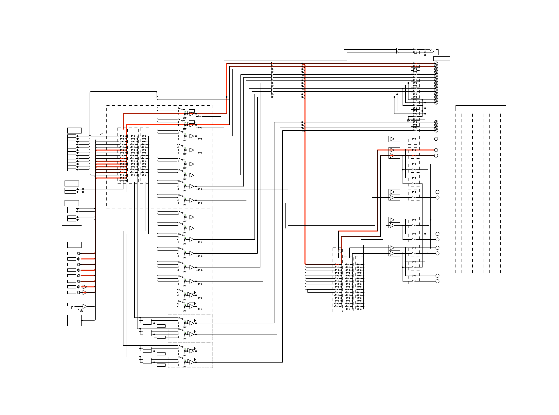
DIAGNOSTICPATHDIAGRAM
fig.01
AVR-X6200W BLOCK DIAGRAM (A.AUDIO/Z2,3HPF)
TO
DIGITAL
AUDIO
BLOCK
DIAGRAN
DAC OUT
FL
FR
C
SW1
SW2
SL
SR
SBL
SBR
FWL
FWR
FHL
FHR
(For Signal DET)
ADC INPUT
MAIN AD-L
MAIN AD-R
ZONE DAC OUT
Z2DA-L
Z2DA-R
Z3DA-L
Z3DA-R
AUDIO
INPUT
GAME
CD
DVR
SAT/CBL
DVD
BD
V.AUX
PHONO
MIC
(For Zone2/3)
DA-FL
DA-FL/FR
Z2L
DA-FR
DA-C
Z3L
DA-SW1
MX
XLR
DA-SW2
V.AUX
DA-SL
MIC
DA-SR
DA-SBL
TUNER
PHONO
DA-SBR
DA-FWL
DVD
SAT/CBL
DA-FWR
DA-FHL
GAME
DA-FHR
CD
BD
EXT-FL/FR
MP
GAME
CD
MP
SAT/CBL
DVD
BD
V.AUX
PHONO
MIC
VOLUME IC1
R2A15220FP
(IN1L/R)
/R
(IN2L/R)
(IN3L/R)
/R
(IN4L/R)
(IN5L/R)
(IN6L/R)
(IN7L/R)
(IN8L/R)
(INAL/R)
(IN9L/R)
(INBL/R)
(IN10L/R)
(IN11L/R)
(IN12L/R)
(IN13L/R)
(IN14L/R)
(REC3L/R)
(ADCR)
(ADCL)
MAIN-L
MAIN-R
MAIN
(MAIN)
ZONE2
(SUB1)
Z2LLINE(SUBR1)
ZONE3
(SUB2)
Z2RLINE
(SUBL1)
Z3LLINE
(SUBR2)
(SUBL2) Z3RLINE
PRE_FL
PRE_FR
EXT-FL
DA-FL
EXT-FR
DA-FR
EXT-C
DA-C
EXT-SW
DA-SW1
EXT-SW
DA-SW2
EXT-SL
DA-SL
EXT-SR
DA-SR
PRE_FL
DA-FWL
PRE_FR
DA-FWR
PRE_FL
DA-FHL
PRE_FR
DA-FHR
PRE_FL
DA-SBL
EXT-SBL
PRE_FR
DA-SBR
EXT-SBR
(FLIN1)
(FLIN2)
(2chLIN)
(FRIN1)
(FRIN2)
(2chRIN)
(SLIN1)
(SLIN2)
(SBLCIN)
(SLCIN)
(SRIN1)
(SRIN2)
(SBRCIN)
(SRCIN)
(CIN1)
(CIN2)
(SWIN1)
(SWIN2)
(SBLIN1)
(SBLIN2)
(SBLCIN)
(SLCIN)
(SBRIN1)
(SBRIN2)
(SBRCIN)
(SRCIN)
(CIN1)
(CIN2)
(SWIN1)
(SWIN2)
(SLIN1)
(SLIN2)
(SBLCIN)
(SLCIN)
(SRIN1)
(SRIN2)
(SBRCIN)
(SRCIN)
(SBLIN1)
(SBLIN2)
(SBLCIN)
(SLCIN)
(SBRIN1)
(SBRIN2)
(SBRCIN)
(SRCIN)
(FLIN1)
(FLIN2)
(2chLIN)
(FRIN1)
(FRIN2)
(2chRIN)
TONE
FL
TONE
FR
C
RSV
SW1
SW2
SL
SR
VOLUME IC2
FWL
FWR
FHL
FHR
SBL
SBR
TONE
Z2L
TONE
Z2R
(FLOUT)
(FLPRE)
(FROUT)
(FRPRE)
(SLOUT)
(SLPRE)
(SROUT)
(SRPRE)
(COUT)
(SWOUT)
(SBLOUT)
(SBLPRE)
(SBROUT)
(SBRPRE)
R2A15220FP
(COUT)
(SWOUT)
(SLOUT)
(SLPRE)
(SROUT)
(SRPRE)
(SBLOUT)
(SBLPRE)
(SBROUT)
(SBRPRE)
(FLOUT)
(FLPRE)
(FROUT)
(FRPRE)
Lch
2
Rch
3
1
H/P OUT
G
PREOUT
PRE_FL
PRE_FR
PRE_C
PRE_SW1
PRE_SW2
PRE_SL
PRE_SR
PRE_SBL
PRE_SBR
PRE_FWL
PRE_FWR
PRE_HL1
PRE_HR1
PRE_HL2
PRE_HR2
PREOUT
FL
PREOUT
FR
PREOUT
C
C
AMPIN
PREOUT
RSV
PREOUT
SW1
PREOUT
SW2
PREOUT
SL
AMPIN
PREOUT
SR
AMPIN
PREOUT
FWL
PREOUT
FWR
PREOUT
FHL
PREOUT
FHR
PREOUT
SBL
PREOUT
SBR
PRE_FL/FR
PRE_SL/SR
PRE_C
PRE_SW1
PRE_SW2
PRE_SBL/SBR
PRE_FHL/FHR
PRE_FWL/FWR
PRE_Z2L/Z2R
PRE_Z3L/Z3R
Z2/Z3 MONO
VOLUME
IC2
R2A15220FP
(IN1L/R)
(IN2L/R)
(IN3L/R)
(IN4L/R)
(IN5L/R)
(IN6L/R)
(IN7L/R)
(IN8L/R)
(INAL/R)
(IN9L/R)
(INBL/R)
(IN10L/R)
(IN11L/R)
(IN12L/R)
(IN13L/R)
(IN14L/R)
(REC3L/R)
(SUB2L/R)
(SUB2L/R)
ZONE3
(SUB2)
ZONE2
(SUB1)
MAIN
(REC3)
P.AMP
P.AMP
P.AMP
P.AMP
P.AMP
P.AMP
P.AMP
P.AMP
P.AMP
+
+
+
+
+
+
+
+
+
+
+
PRE_Z2L
PRE_Z2R
PRE_Z3L
PRE_Z3R
CENTER
FL
FR
SL
SR
SBL
SBR
WL
WR
HL
HR
9ch AMP SP OUT
NOR
MAL
HEI
GHT
FL
FR
SL
SR
SBL
SBR
---
--FHL
FHR
No2
NOR
MAL
WIDE
C
FL
FR
SL
SR
SBL
SBR
FWL
FWR
---
---
7ch
BIAMP
FL
FR
SL
SR
SBL
SBR
FL
FR
---
---
9ch
BIWIR
ING
HEI
GHT
SBL
SBR
FL
FR
FHL
FHR
CCC
FL
FR
SL
SR
9ch
BIWIR
ING
WIDE
C
FL
FR
SL
SR
SBL
SBR
FL
FR
FWL
FWR
No6No5
7ch
7ch
+Z3
+Z2
FL
FR
SL
SR
SBL
SBL
SBR
SBR
------
------
Z2L Z3L
Z3RZ2R
FL
FR
SL
SR
No8CCNo7No3 No4No1 No9
5ch
+Z2
+Z3
C
---
FL
---
FR
---
SL
---
SR
---
Z2L
---
Z2R
---
---
---
---
--Z3L
---
Z3R
---
TUNER:
NA/EU/AP
ALL MODEL
TUNER
MONO
HPF
MONO
HPF
MONO
HPF
MONO
HPF
MONO
MONO
MONO
MONO
FULL
MONO
HPF
HPF+MONO
FULL
MONO
HPF
HPF+MONO
FULL
MONO
HPF
HPF+MONO
FULL
MONO
HPF
HPF+MONO
TONE
TONE
TONE
TONE
ZONE2
NJW1194
ZONE3
NJW1194
PREOUT
Z2L
PREOUT
Z2R
PREOUT
Z3L
PREOUT
Z3R
30
 Loading...