

Demon 421441 User Manual
Item
Description
Qty.
Item
Description
Qty.
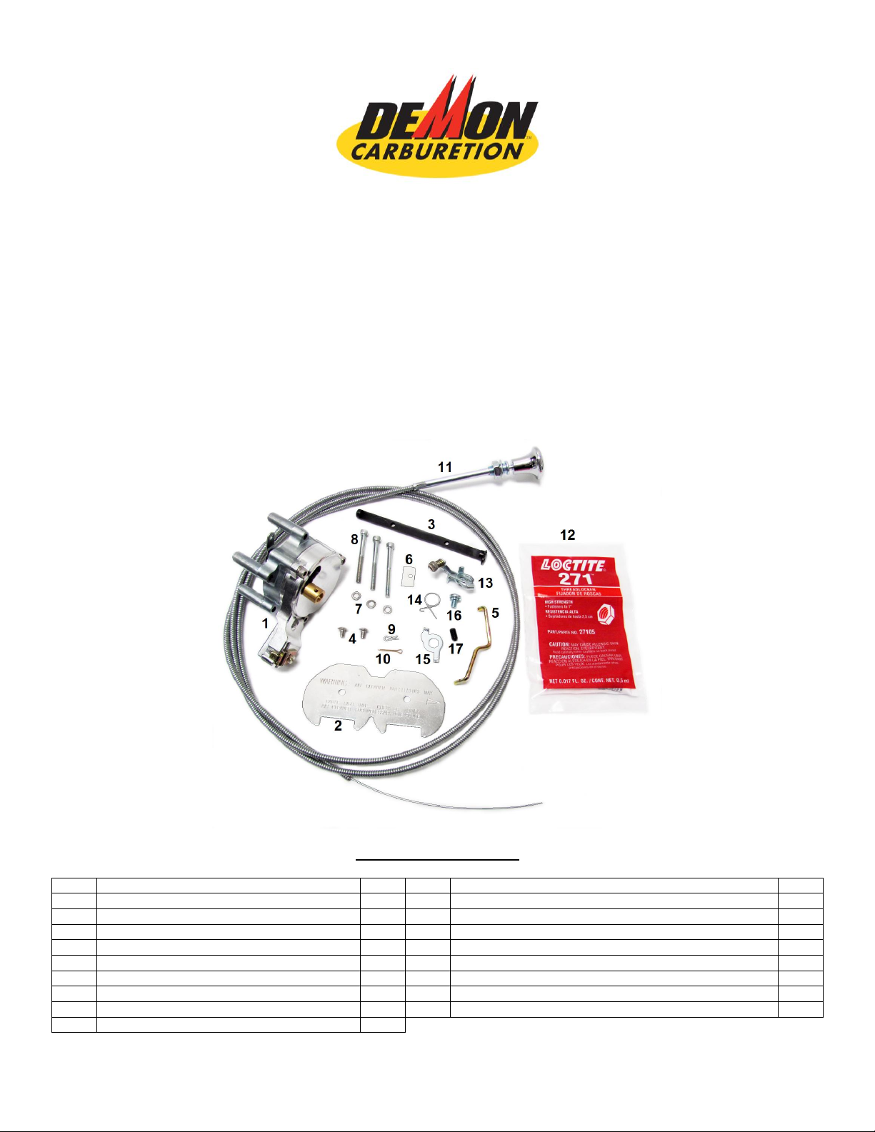
1
Manual Choke Pod Assembly
1
10
1/2” Cotter Pin
1
2
Choke Flap
1
11
6 ft. Choke Cable
1 3 Choke Shaft with Lever
1
12
Tube of Loctite® 271 (packaged)
1 4 #8 x 32 TPI Torx® Head Screws
2
13
Fast Idle Assembly (plate, spring, & screw)
1 5 Choke Rod
1
14
Shaft Spring
1
6
Nylon Main Body Block Off Plate
1
15
Outer Shaft End Plate
1
7
#8 Lock Washers
3
16
#10-32 x .31” Phillips Pan Head Screw w/ Lockwasher
1 8 #8 1-3/4” Socket Head Cap Screws
3
17
#10-32 x .38” Set Screw
1 9 1/2” Retainer Pin
1
DEMON™ CARBURETOR MANUAL CHOKE KIT
#421441
CHOKE INSTALLATION INSTRUCTIONS
LIT703
This manual choke kit is designed to be used on any Demon™ Carburetor with a choke tower. This covers the
Road Demon Jr.™ and Road Demon™ series carburetors as well as both Twin Squirter (mechanical
secondary) and Vacuum Secondary Speed Demon™ carburetors. READ THESE INSTRUCTIONS
THOROUGHLY before installing the Demon™ Carburetion Manual Choke Kit. If you have any questions,
please contact our technical department at 270-901-3346.
INCLUDED IN THIS BOX
1
You will need the following tools to help with the installation:
Small Hammer
Small Drift (punch)
3/32" Allen Wrench
9/64" Allen Wrench
T15 Torx Driver
.316 Diameter Drill
Needle Nose Pliers
Small Flat Blade Screw Driver
#2 Phillips Head Screw Driver
Small File
INSTALLATION
1. Remove the carburetor from the vehicle and drain any fuel into a “fuel safe” container.
2. If your carburetor is a Speed Demon™ Twin Squirter (mechanical secondary), it is equipped with a slotted
screw to control the secondary butterfly position. This must be changed to the #10-32 x .38 set screw
included with the kit (if you do not, the linkage can bind). This will require you to reset the secondary
throttle shaft. Set the secondary butterflies to the bottom of the transfer slot so you cannot see any of the
slot at idle (butterflies closed), but with any movement of the secondary butterflies you will begin to see the
slot. (Refer to the Demon™ carburetor instruction manual for further information.)
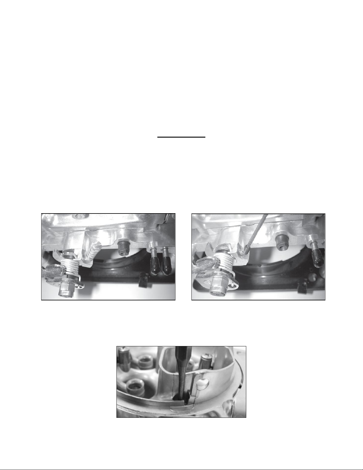
Figure 2 Figure 3
3. Using a small drift pin punch, knock out the sealing slug on the right side of the choke horn in the main
body. It is precut at the factory and should press out very easily. Once you’ve removed the slug, deburr the
hole to make sure the choke rod doesn’t bind or hang.
Figure 4
2
4. Insert the nylon main body block off plate into the cut out slot in the side of the main body.
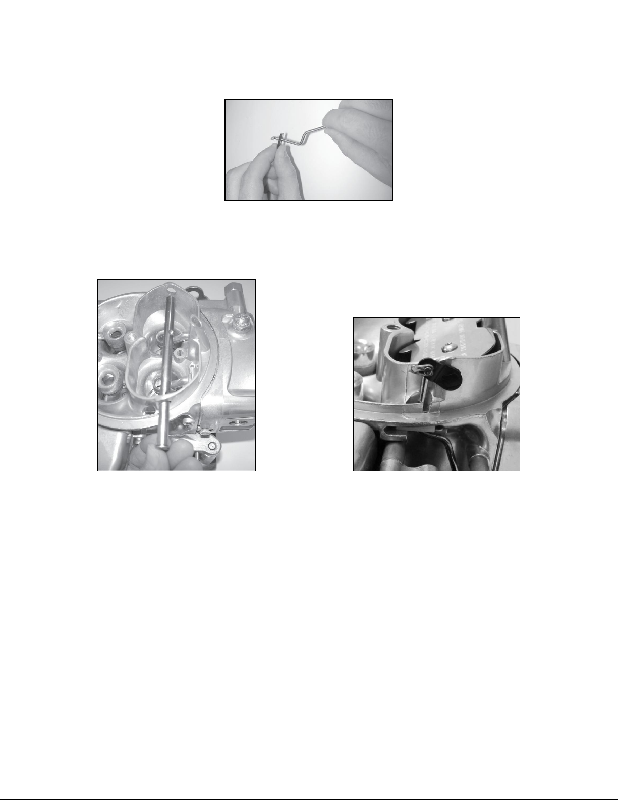
5. Insert the small end of the choke rod through the bottom of the nylon main body block off plate towards the
top (Fig. 5).
Figure 5
6. Insert the choke shaft with lever through the choke tower (Fig. 6). Make sure the choke shaft with lever
moves freely before proceeding. If it does not you may need to resize the hole(s) going through the choke
tower or use a 0.316" drill bit to make sure the hole is the proper size.
Figure 6 Figure 7
7. Insert the choke rod through the hole on the end of the bracket on the choke shaft. Secure the rod with the
1/2" cotter pin (Fig. 7).
8. Use the two T15 Torx® head screws to secure the choke flap to the choke shaft (Fig. 8). The flap has
instructions stamped on its upper side. Make sure you can read the instructions and that the arrow points
towards the choke rod. NOTE: It is extremely important that the choke flap is centered so it moves freely
and does not bind. You may need to remove the flap to deburr the edges if it binds and reinstall. Once the
choke flap is centered and moving freely, remove the Torx® head screws one at a time. Place a drop of
Loctite® 271 on them and reinstall. Wipe any excess Loctite® off the screw heads or shafts before
proceeding.
3
 Loading...