

Demon 1920 User Manual
STREET DEMON™
CARBURETOR REBUILD KITS
625 Street Demon™ #1920
750 Street Demon™ #1919
INSTRUCTION SHEET - LIT709
1
DISASSEMBLY:
NOTE: Numbers in parentheses refer to the exploded views in Figures 10 & 11.
1. Remove the choke shaft / lever assembly (5). Remove step up piston cover screws (2) and step-up piston cover
(1). Remove the step up pistons (19), metering rods (15), and springs (14) as an assembly. Metering rods (15)
may be removed from the piston (19), if desired.
2. Remove the pump lever connecting rod (32), c-clips (31), choke connector rod (42), c-clip (31), and cotter pin
(46). Remove the 8 assembly screws (36).
3. Lift the air horn straight up from the fuel bowl to avoid damage to the parts attached. Remove the float pins (8),
floats (9), and fuel needle seat and gasket assembly (20), and strainers (26). Remove the air horn gasket (28).
4. Separate the fuel bowl from the throttle body. Remove the choke cap retainer screws (41), choke cap retainer
(40), choke cap assembly (39), and choke cap gasket (38).
5. Remove the throttle body gasket (34). Set the throttle body (35) and fuel bowl assembly (30) aside for cleaning.
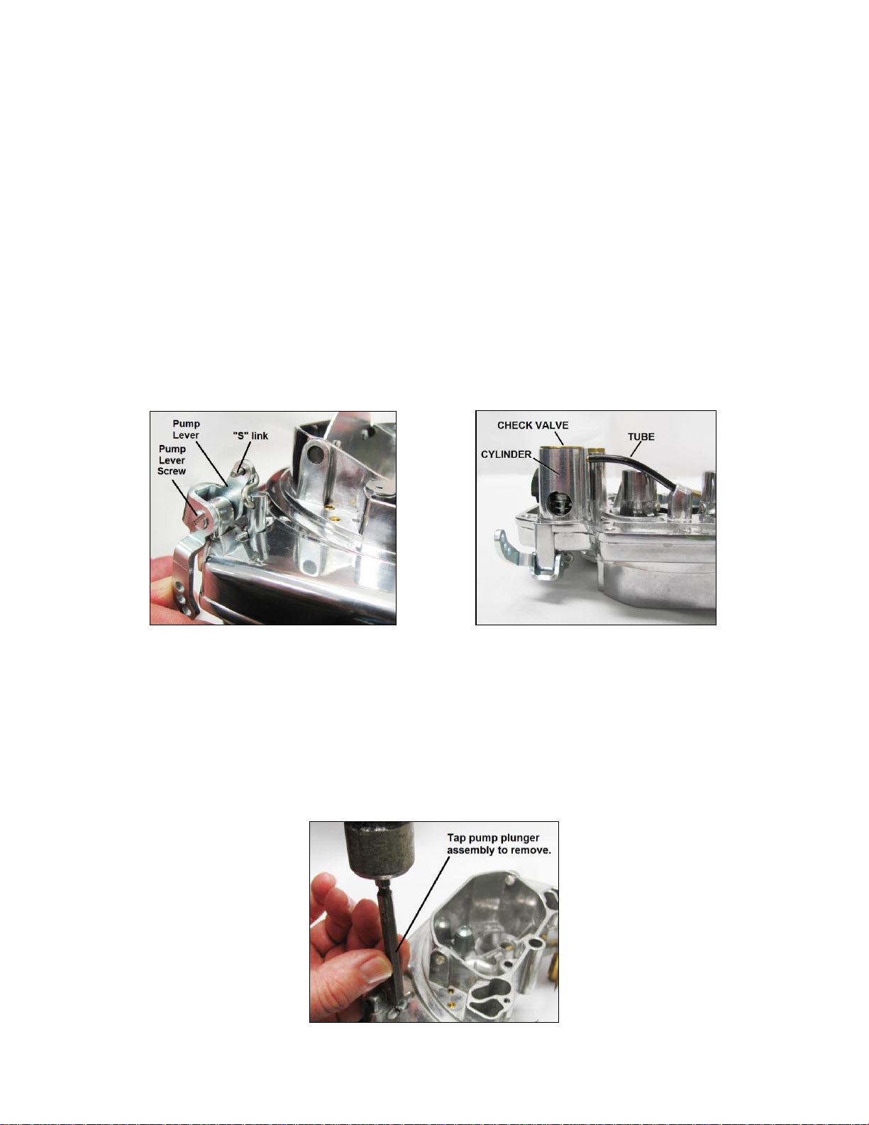
6. Remove the pump lever screw (4), pump lever (3), and pump “S” link (21) from the end of the plunger stem (Fig.
1). Remove the fuel inlet fitting (16) and gasket (17).
Figure 1 Figure 2
7. The accelerator pump cylinder is part of the air horn casting and connects to the discharge nozzle in the primary
section through a short flexible tube (Fig. 2). The intake check valve assembly acts as a bottom closure for the
pump cylinder.
8. Remove the accelerator pump intake check valve (12) and accelerator pump assembly (10). The accelerator
pump intake check valve fits tightly into the bottom of the accelerator pump cylinder and can be removed by
tapping lightly on the end of the pump plunger shaft. Tap the end of accelerator pump plunger carefully to guard
against damage to the shaft or the air horn assembly (Fig. 3). Once the accelerator intake check valve is
removed, carefully pull the accelerator pump assembly from the air horn.
Figure 3
2
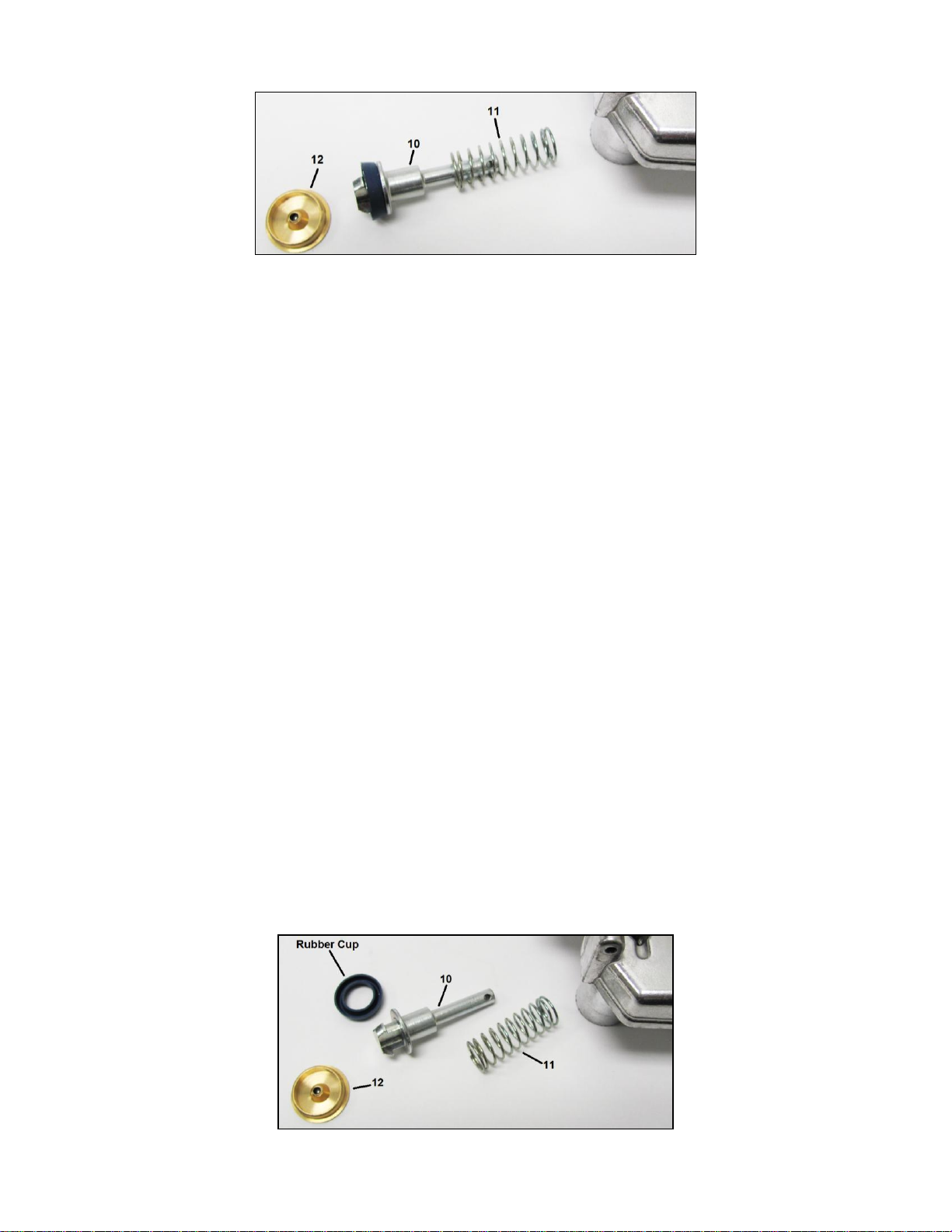
9. Remove the accelerator pump plunger assembly (10) and spring (11). See Fig. 4.
Figure 4
10. Remove the rubber cup from the pump plunger assembly.
11. Remove the primary (6) and secondary jets (13), noting their locations.
12. Remove the discharge nozzle screw (23), discharge nozzle (22), and discharge nozzle gaskets (24). Invert the air
horn to remove discharge check needle (25).
13. Remove the idle mixture screws (47) and springs (48) from the throttle body assembly (35). Remove any rubber
vacuum caps at this time.
CLEANING:
Clean all parts thoroughly in an approved cleaning solvent or lacquer thinner. Special attention should be given to carbon
deposits in throttle bores and passages. Do not use wires or pointed tools to clean passages and calibrated holes as
calibration of carburetor may be destroyed. Do not immerse rubber or similar materials in cleaning solvent.
REASSEMBLY:
Reverse the disassembly sequence. Note the following special instructions:
1. To ensure proper usage of gaskets and parts packaged in kit, use old gaskets and parts for identification.
2. Idle mixture screws should be seated lightly and then backed out approximately 1-1/2 to 2 turns for initial setting.
3. Install the new accelerator pump rubber cup on the pump plunger assembly (10). See Fig. 5.
4. Push the accelerator pump stem into the accelerator pump cylinder to compress the spring. Install the new brass
accelerator pump intake check valve. Avoid contact with the check valve orifice area during assembly. Install
open end of “S” link in pump shaft toward choke valve.
5. Refer to Adjustment Data for adjustment specification (Fig. 6 & 7).
6. When installing the choke cap, be sure the pick-up lever (in the housing) fits into the loop on the bi-metal spring.
Proper assembly may be verified by turning the choke cap in both directions. The choke plate should open when
rotated clockwise, and it should close when rotated counter-clockwise.
Figure 5
3
 Loading...