

Demon 190000 User Manual

CARBURETOR REBUILD KIT
190000 (Vacuum Secondary)
Models – Demon Carburetors & Holley Model 4160™
LIT704
INSTRUCTIONS:
Before getting to the actual rebuild, it should be noted that the carbs shown here are Demon™ Series
carburetors. It may not be identical to the carb on your engine, but it will be very similar. All Demon™
and HOLLEY® four barrels (with the exception of the 4360 Q-Jet replacement), may be disassembled
the same way. A few parts differ here and there, but that doesn't alter the rebuild procedure.
You will need the following tools to complete the rebuild:
5/16" nut driver
Standard & Phillips Head screwdrivers
5/8" open end wrench for the float adjusting nut and fuel line fitting on some models (an 11/16"
open end wrench might be required in some cases)
1" socket for the power valve and a 1" open end to remove the fuel inlet adapter fitting
Needle nose pliers will help in removing small retaining clips and pins
Clutch-type screwdriver to loosen the secondary metering plate screws used on Model 4160™
carbs (the ones that do not have replaceable secondary jets)
Open end 3/8" and/or a 7/16" wrench to adjust the accelerator pump override spring
1/4” and 9/64 Allen wrenches
Demon™ and HOLLEY® Four Barrels are actually an easy carburetor to rebuild because of their
construction. If you group everything in subassemblies, it is hard to go wrong. When you reassemble
the carburetor, install all of the parts on the metering block, and then set it aside. Do the same with
the fuel bowl, main body, and the throttle body assemblies. When all of the subassemblies are
completed, you will only have six pieces to bolt together to complete the assembly process.
Reassembly is done by simply reversing the disassembly steps. Before installing the carburetor on
the intake manifold, rotate the idle mixture adjusting screws clockwise until they lightly bottom out in
the metering block. Then, turn 1 and ½ turns to get the initial idle setting in the. Also, adjust the
accelerator pump override spring by tightening the nut until some clearance is visible between the
bolt head and pump lever. Back the nut off until all clearance is removed and then rotate it another
1/8 turn. Setting the initial float level may be done easily by inverting the fuel bowl (before it is
installed). Run the new fuel inlet (needle & seat) assembly in until the top of the float is parallel with
the roof of the fuel bowl.
1
Once a Demon™ carburetor is in place and the engine is running, the level should be set such that it
is in the middle of the sight window. Again, adjust the idle mixture screws to provide the highest
manifold vacuum or engine RPM.
Once a HOLLEY® carburetor is in place and the engine is running, the level should be set so that fuel
is just below the inspection hole and the mixture screws should be adjusted to provide the highest
manifold vacuum reading or engine RPM.
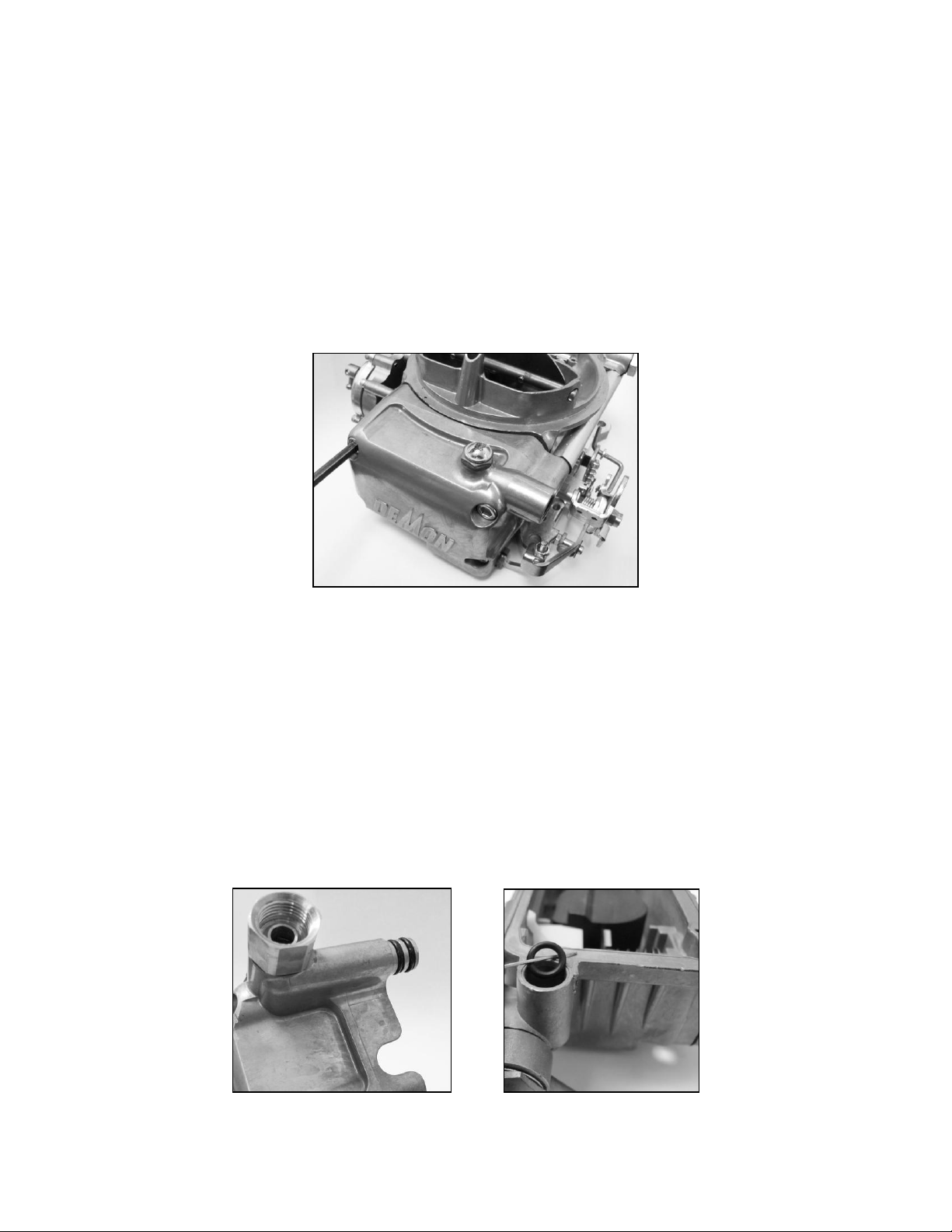
1. Remove the primary fuel bowl. Four screws, located at each corner of the bowl (Fig. 1), hold both
it and the metering block in place. When either one of the lower screws is loosened, fuel will begin
seeping out, unless the carb has been drained. If the carburetor has been in service for some
time, the screw gasket will tend to stick to the fuel bowl.
Figure 1
2. Once all four screws are removed, the bowl can be pulled away from the metering block.
Depending upon the age of the carburetor, this may not be quite as easy as it seems. Some
carburetors are assembled with composition gaskets and some were coated with a sealing resin
to eliminate fuel vapor seepage. A gentle pry with a wide blade screwdriver should solve the
problem. The same technique must also be applied to the metering block in order to separate it
from the main body. Demon Carburetion™ Model 4160 Road Demon Jr. has 2 external o-rings
visible when transfer tube is removed (Fig. 2). When the fuel bowl is pulled from a carburetor with
a single fuel inlet, the "O"-ring that seals the fuel transfer tube will generally remain inside the
housing (Fig. 3 refers to Holley ® Model 4160 ™). It should be pulled out and discarded at this
point, so that it doesn't become mixed with the new rings. The inlet fitting may be removed with an
11/16” wrench.
Figure 2 Figure 3
2
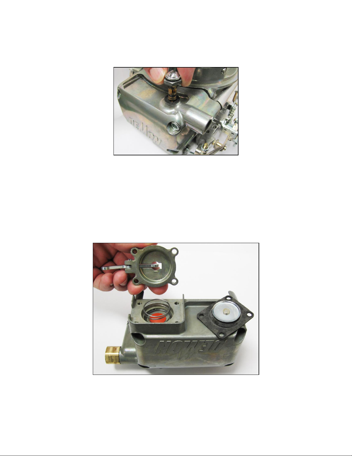
3. After removing the lock screw, the fuel valve & seat assembly may be rotated counter-clockwise
with a 5/8-inch wrench. Once the threads are no longer engaged with the bowl threads, the entire
assembly can be extracted (Fig. 4). O-rings may provide some resistance which can be easily
overcome by pulling straight upward.
Figure 4
4. The plastic baffle installed in the fuel bowl should be removed and reinstalled when the carburetor
is assembled. This baffle is essential to proper float operation and should not be left out. Dual feed
bowls utilize the inlet cavity as a baffle, so a separate piece is not required.
5. Removal of four Phillips screws allows the accelerator pump housing to be lifted from the fuel bowl
(Fig. 5). The pump diaphragm is located below this cover. This should now be discarded as a new
diaphragm is included with your package. A return spring is located beneath the diaphragm and it
should be saved for reuse.
Figure 5
6. The metering block must also be stripped of its removable parts prior to being cleaned. The jets
should be removed with a wide-blade screwdriver.
3
 Loading...