

Demon 1563010VE User Manual

INSTRUCTION MANUAL
To download this manual or others, go to: www.demoncarburetion.com
1
INTRODUCTION
Demon Carburetors™ have many unique features that make them the ultimate choice for racers, like
yourself. Whether it is street / strip performance, or just getting the most out of your hot rod, the
Speed Demon™ will give you the necessary edge over others. This manual will discuss the special
points and unique features of the carburetor, and the correct procedures for proper installation and
tuning. The goal is to help you understand the thoughts behind the Demon™, and to increase your
knowledge of carburetion on a whole. Please read and understand this manual completely to assure
that you get the most out of your new Demon™ carburetor.
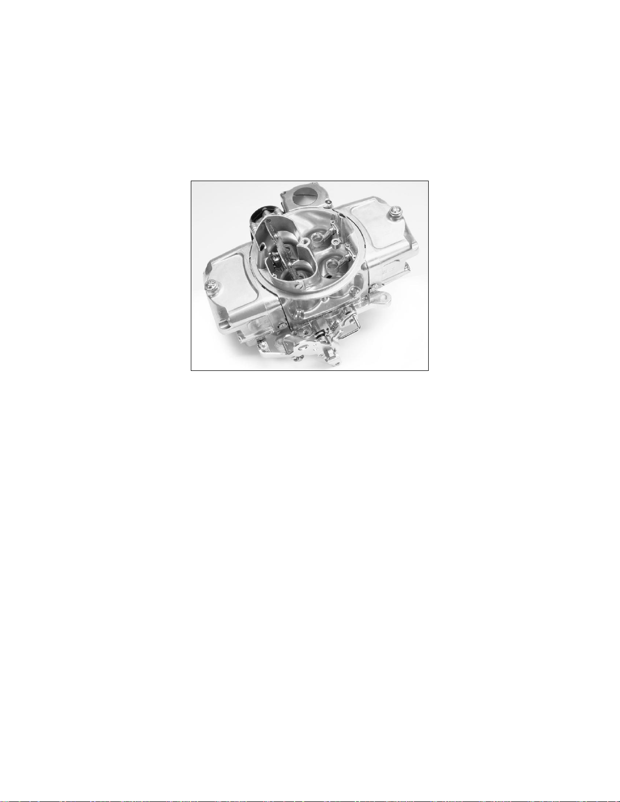
Figure 1
INSTALLATION
Checking the Baseline Adjustments
All baseline adjustments have been made at the factory during the final assembly stage of each
carburetor. These settings should allow initial start and warm up of the engine. However, in order to
assure safe operation, and to assist with fine tuning that will occur later, please check and make note
of the following adjustments, prior to installing the carburetor on the engine.
Throttle and Accelerator Pump Linkage
1. Check the travel of the throttle linkage to be sure no damage has occurred during handling or
shipping after its final assembly. The carburetor should open smoothly to wide open throttle, and
return to its full closed position when the linkage is released. At wide open throttle, all butterflies
should be parallel to each other, at about a 90º right angle to the baseplate gasket surface. Do not
attempt to run a carburetor that opens the secondaries past full throttle, or sticks or binds at any
point in its travel.
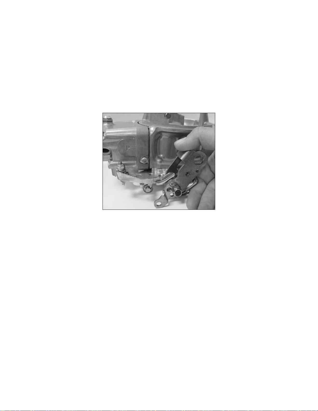
2. When the carburetor is in the closed (curb idle) position, there should be no play in the adjustment
of the accelerator pump arms. The pump levers should begin compressing the pump diaphragms
as soon as the linkage begins to move. Play in the pump arm linkage will delay the fuel discharge,
and the result is usually a stumble or hesitation as the carburetor begins to open. At wide open
throttle, check to be sure that .015" to .020" travel remains in the accelerator pump linkage. If the
pump diaphragms bottom out, premature wear or binding in the linkage will occur.
2
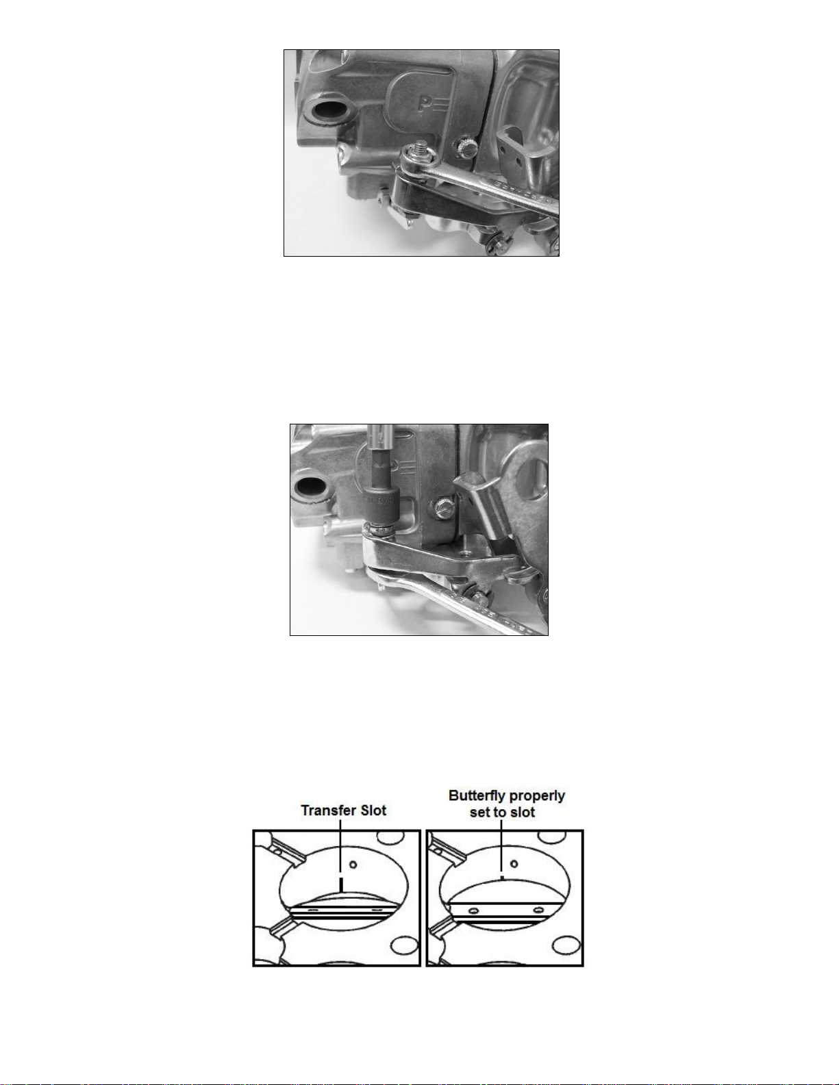
Figure 2
3. Slop in the linkage can be adjusted out by either tightening or loosening the lock nut. This will
control the length of the compressed spring. Slightly bend the cam follower to adjust for linkage
that bottoms out. Remember, it may take a balance of both cam follower and spring adjustments
to get the system working best for the application. Different cam profiles are available which can
alter the timing, volume, and duration of the pump shot. If pump cams are changed, it may be
necessary to re-adjust the linkage.
Figure 3
Closed Butterfly Position
The initial setting of the closed butterfly position will vary slightly between carburetor model sizes and
fuel types. Most gasoline carburetors will have the butterflies adjusted with a small length
(approximately .020", looking like a square) of the idle transfer fuel slot visible below the bottom edge
of the butterflies (Fig. 4).
Figure 4
3
Primary and secondary butterflies should be open equal amounts, and never seated tightly against
the throttle bores in the baseplate. Butterfly position is adjusted using the idle set screws (Fig. 5) in
the baseplate. Turn the screws clockwise to open the butterflies, or counterclockwise to close them
down. Be sure to note the adjusted position of your model carburetor, as this can be important
information used later during fine tuning.
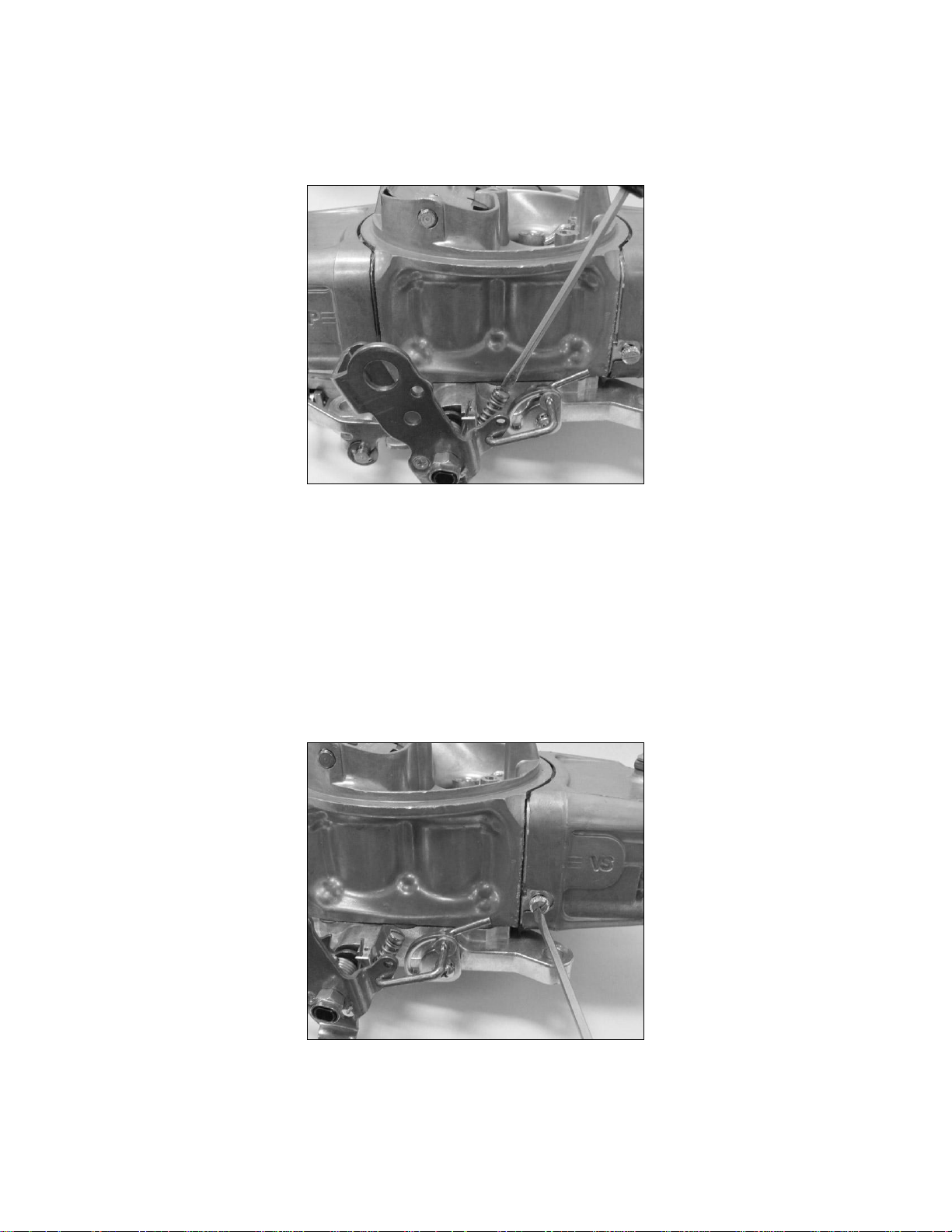
Figure 5
Curb Idle Mixture Screws
The curb idle mixture screws (total of 4) are located on each side of the metering block (Fig. 6).
These screws control the amount of idle fuel mixture that will be discharged into the plenum from the
curb idle ports located in the baseplate. These screws have been set during wet-flow testing at the
factory and it is recommended that they remain in place as delivered for initial start-up.
Keep in mind that these settings are only a starting point, and that additional fine tuning may be
required once the engine has warmed up to operating temperature.
Figure 6
4
Bolting the Carburetor to the Manifold
After the linkage and baseline settings have been checked, the carburetor is ready to be bolted to the
manifold. Be sure to use the supplied gasket. The carburetor should slide easily over the studs. Do
not force the carburetor if it hangs on the studs. If the carburetor does hang up, check for bent or
improperly installed studs. Replace the studs if necessary. Once the carburetor is seated against the
gasket, check to see that it sits squarely on the mounting flange.
The carburetor should not be able to be rocked diagonally. A carburetor that rocks is an indication
that the manifold or carburetor spacer could be warped. This must be corrected before the carburetor
is bolted down. When the carburetor sits squarely, it is safe to install nuts and washers. Be sure all
nuts are installed on the studs and hand tight before beginning the final torque sequence. Use an
alternating pattern, to tighten each nut a little at a time (Fig. 7). Do not over tighten the nuts. Only 5-7
foot pounds of torque are required to secure and seal the carburetor base to the manifold. Once the
nuts are evenly torqued, check the carburetor linkage for smooth operation to wide open throttle, and
then closed again.
WARNING: Baseplates that are cracked during installation are not covered under warranty.
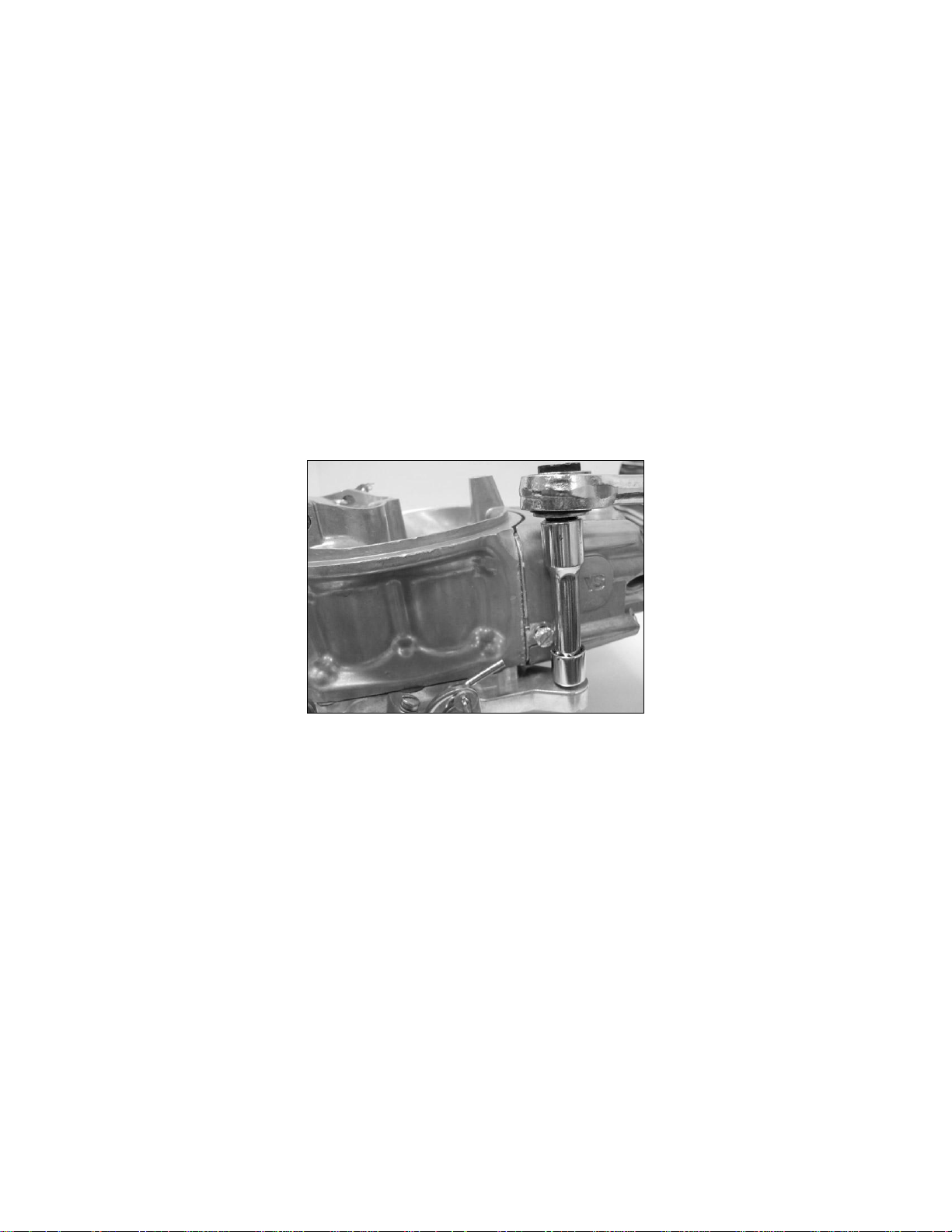
Figure 7
5
Connecting the Throttle Linkage
DO NOT RELY ON THE BASEPLATE LINKAGE AS A STOP! FAILURE TO USE A POSITIVE
PEDAL STOP CAN RESULT IN LINKAGE DAMAGE THAT CAUSES THE THROTTLE TO STICK
IN THE WIDE OPEN POSITION.
With the pedal held firmly against a stop, pull the carburetor to its wide open position (Fig. 8). Adjust
the linkage rod or cable to the proper length, and then attach it to the baseplate linkage. Remember,
the pedal should come against a positive stop, just as the carburetor gets to wide open throttle. With
the linkage rod attached to the baseplate, make sure the carburetor can return to its closed position.
Install your return spring(s), and check again for smooth operation to wide open throttle, and then
closed again.
Figure 8
Connecting the Fuel Lines
Always use lines and fittings that are built for automotive use, and compatible with your type of fuel.
Stainless steel braided, or push-lock type reinforced hose with AN swivel connections are
recommended on all fuel lines. Do not use thread lockers, sealing compounds, or Teflon tape on
AN flare fittings. When installing fuel bowl inlet fittings, use only the sealing washers or o-rings
provided with the fitting.
In most cases, a drop of oil to prevent thread galling is all that’s necessary when installing pipe
threaded fittings. However, if a thread sealant is used on pipe fittings, use extreme caution to prevent
any tape or compound from entering the internal flow area. Remember to check for leaks when the
system is under pressure. If a leak is detected, replace the malfunctioning part. When installing new
fuel lines, be sure to flush the lines clear of any debris that might remain from the hose cutting or
assembly process.
6
 Loading...