

Page 1
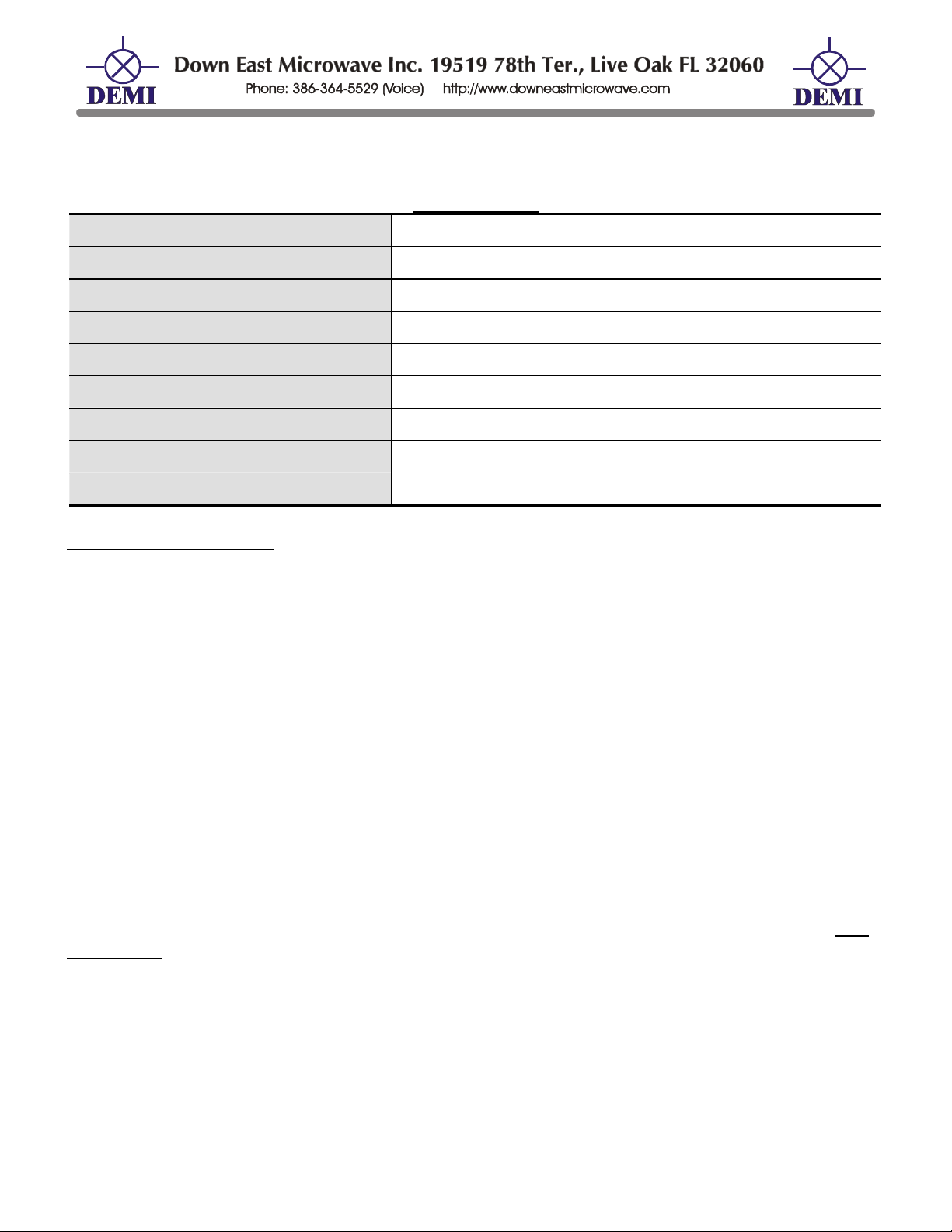
DEM Part Number 2304-144_____
13 cm Transverter Serial Number________
Specifications
Frequency after 10 Min warm-up: 2304.100 MHz. = 144._____________
Noise Figure and Gain: 1.9 dB nom. > 17 dB Gain
Power Out: 20 mW 1 W Other_____________
DC Power Requirement: 10 - 15.5 VDC @ 1 Amp
IF Option: Common or Split
IF Drive Level Requirement Option: 10 mW 1-10W Other_____________
Keying Option: PTT - to ground TTL - Positive Voltage
Aux. Connection Output Option: Ground on TX + Voltage on TX_____________
TR Switch Option: None Installed Supplied
Operating Instructions:
This DEM 2304 transverter is a combination of circuit boards designed by KK7B, and Down
East Microwave Inc. All circuitry operates from a internal 9 VDC Regulated supply which makes it
an ideal portable rig or it can be easily implemented into an existing home station. Please review
all options installed in this transverter before interfacing to a standard 2 Meter IF rig. Interfacing
can be simplified by using one of the various interfacing options available from DEMI or simply
configure your 2M IF rig yourself to correspond with the options installed in the transverter. If you
are unsure of the options installed or of the correct way to interface your 2M IF rig, please consult
DEMI to avoid unnecessary damage to your transverter.
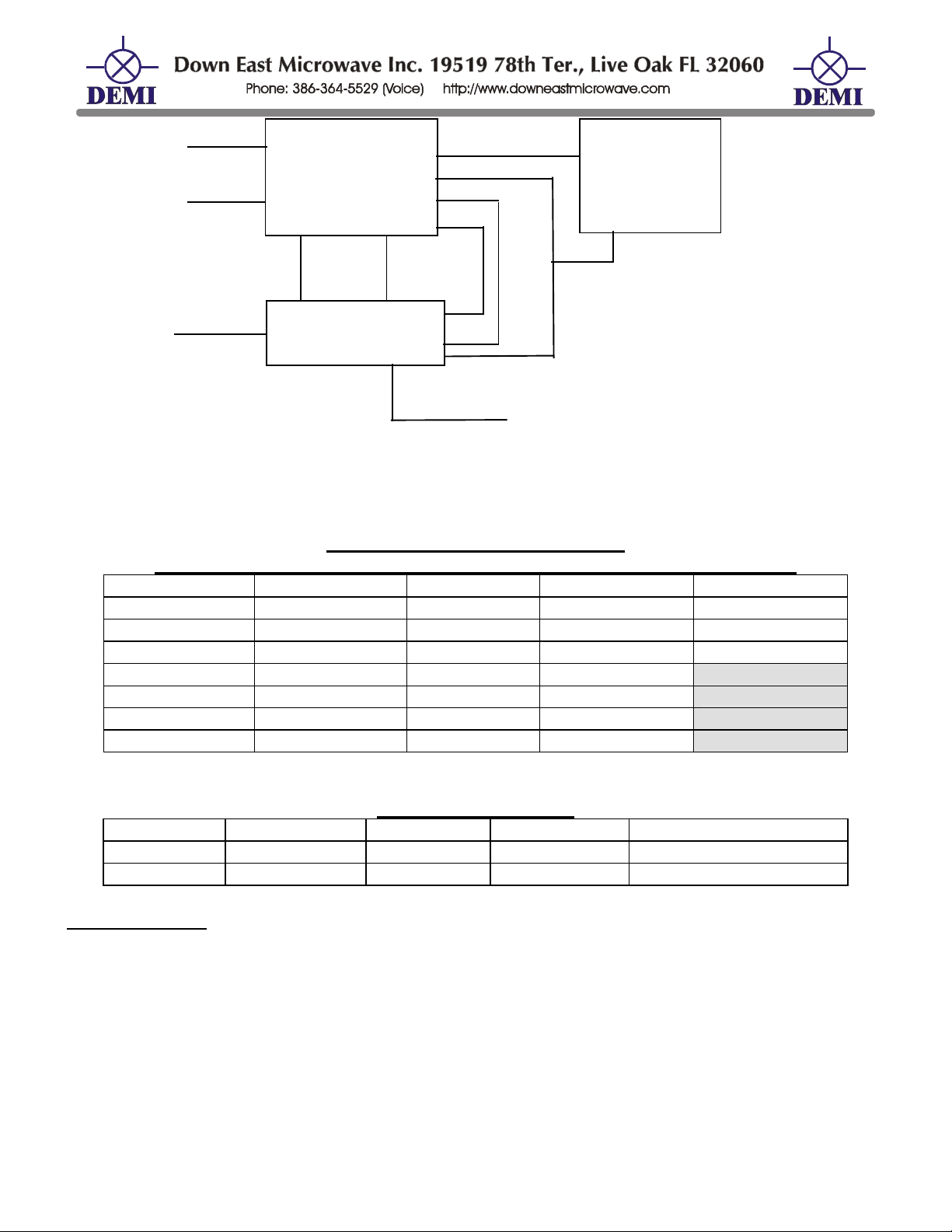
A block diagram is supplied to show the DC wiring of the transverter and the interfacing of
the various circuit boards used in the transverter. This is provided for information and location of
adjustment points to aid in your station integration. This will also aid you if you decide to add a
pre-amp, power amp, T/R switch or sequencer to your system or to install or disable the various
available options. Schematics and circuit board diagrams are also provided for all of the internal
electronics.
Once all interfacing is complete operation is simple. Please note frequency calibration listed
on the top of this document. Remember the transverter should always be “hard-keyed”. It is
RF sensed. If your 2M IF rig does not have an external keying line (Push to Talk to Ground, PTT
or Positive Voltage on Transmit, TTL) you will need to install one. You should consult your manual
or the manufacture for details.
Output power levels, receive gain and frequency may be adjusted internally on the TC by
removing the top four screws and opening the cover. Be careful because the local oscillator is
attached on the bottom of the top cover and is connected to the main transverter board by coax.
/Built/2304op.doc 1 Rev. A 1/14/08
not
Page 2
TXIF RXIF
X
Common IF
TXRF +VTX PTT TXRF 13.8V RXRF
PCB
Mounting
Plate
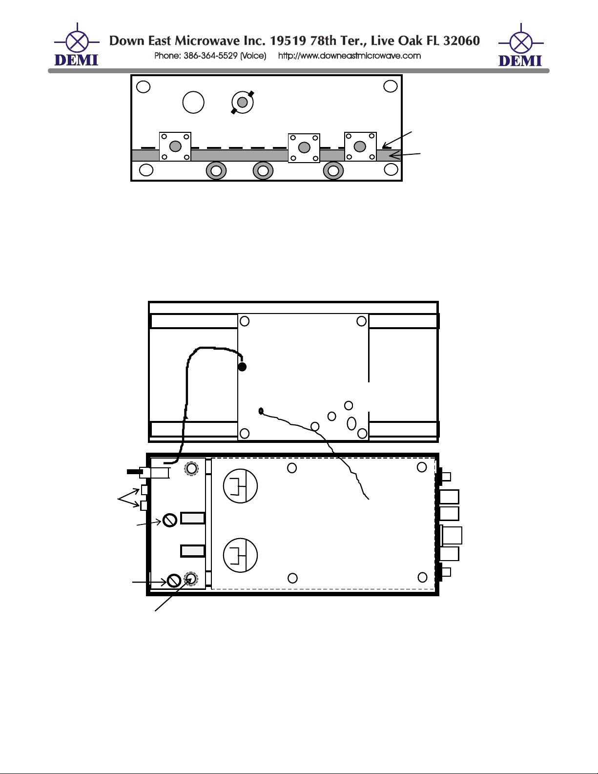
Rear Panel Diagram
The 1 watt output version will have a extra SMA connector installed. The TXRF connector will be
mounted by the RXRF connector so that a common SMA type relay may be connected to perform
the TR function. The connector in the old TXRF position will be a dummy connector and will not be
connected to any circuitry.
MICRO LO PCB
9V DC
(Ground Plane)
Trimmer
Capacitor
COA
Rear
Panel
Switch
LED
RX Adjust
TX Adjust
Mounted on
Stand-Offs
LO output
RX
TC PCB
2304 PCB
TX
Enclosure and PCB Mounting
/Built/2304op.doc 2 Rev. A 1/14/08
Page 3
TX RF
RX RF
1080 MHz. LO
2304 Transverter PCB
LO
M2 M1
RX IF
2M IF
TC
10WMax.
+TX
TX IF
+13.8VDC
+LO
+RX
+9 VDC
Wiring Block diagram
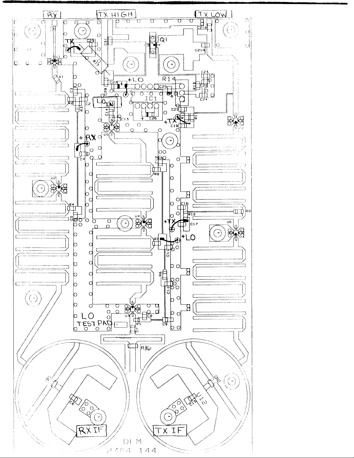
2304 Transverter Board Parts List
All components are Surface Mount components unless otherwise noted.
C1 8.2 ρF ATC C12 0.1 µF R1 10 Ω R11 130 Ω
C2 0.1 µF C14 10 ρF R2 51 Ω R12 130 Ω
C3 10 ρF C15 100 ρF R3 150 Ω R13 100 Ω
C4 0.1 µF C16 10 ρF R4 130 Ω
C5 0.1 µF C17 0.1 µF R7 130 Ω
C6 100 ρF C19 0.1 µF R8 130 Ω
C7 10 ρF C20 10 ρF R9 51 Ω
C11 0.1 µF C21 10 ρF (A&B) R10 100 Ω
U1 MGA86576 CR2 MA4E2054
U2 ERA-1
U3 ERA-1
U4 ERA-2
U5 ERA-2
U6 ERA-2
U7 ERA-4
CR1 MA4E2054
2304-144 PA SECTION
C22 10 pF
C23 0.1 µF C26 10.0 µF C29 0.1 µF
C24 0.1 µF C27 10.0 µF
C25 10.0 µF C28 0.1 µF R13 51 Ω
C30 10 pF
R14 10K pot Q1 FLC 103
R15 1Ω, 1Watt
IC1 7660
2- sets of 0-80 screw, nut
Test and Setup:
1. You will need to hard-key this transverter. It is not RF senesced! If you wish to have your
transceiver key the transverter, you will need to use the auxiliary contacts or a positive voltage
on transmit generated by your IF transceiver.
2. The transverter in its stock form will only safely accept the IF drive level indicated on the front
page. If you wish to use a transceiver with a different drive level, you will need to modify the
TC as per its document or supply additional attenuation. A receive IF gain stage may be added
to the TC to compensate for the additional attenuation.
3. RX and TX levels may change when the enclosure is completely assembled. Please take this
into consideration when adjusting final levels.
4. Frequency of the LO will change over time. The more “Burn in” before actual use, the better!
/Built/2304op.doc 3 Rev. A 1/14/08
Page 4

DEM TC
DEM TRANSVERTER CONTROL
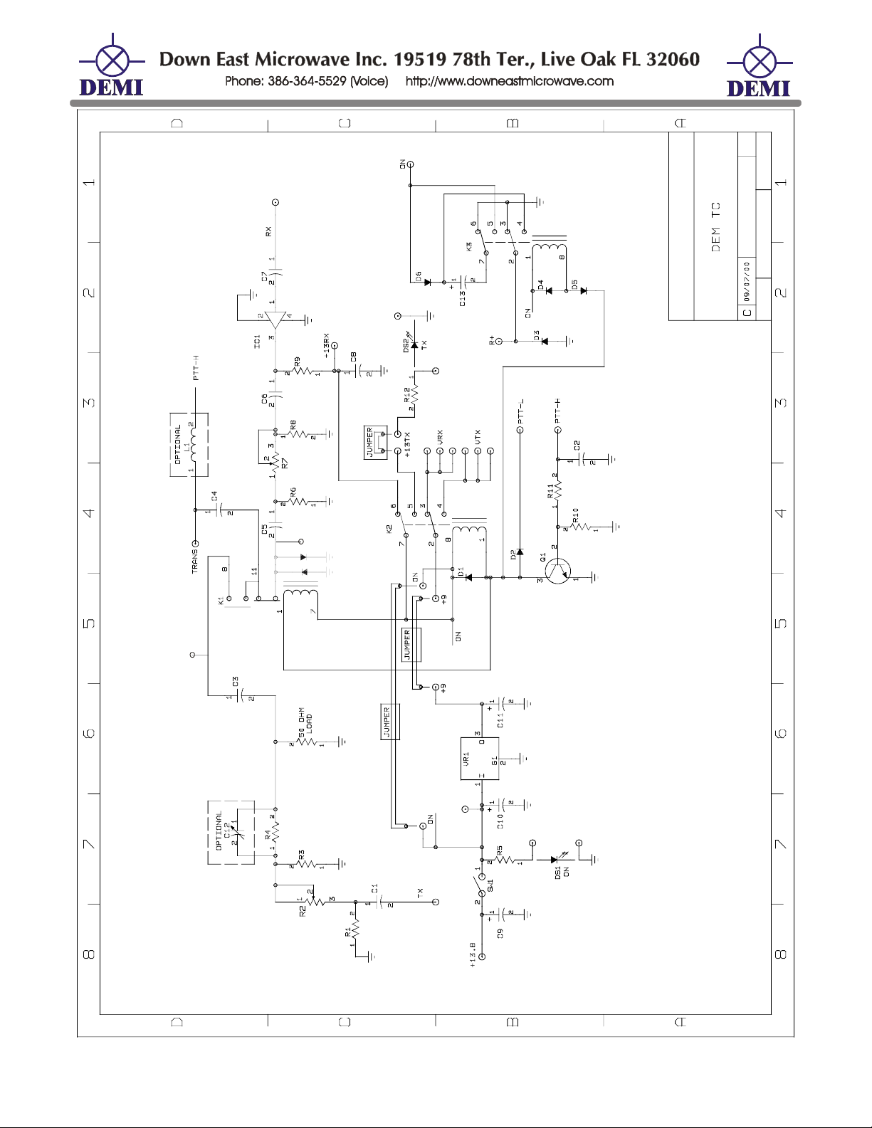
The DEM Transverter Control (DEM TC) is the circuit board that controls all transverter
functions in the DEMI 2.3 GHz. -10 GHz. transverters. It was designed with many options and
depending on the configuration you have ordered (see configuration page of main transverter
document), the options may or may not be enabled in your transverter. This document will cover
all of the features available for understanding and make it possible to change the configuration at
any time to suit your requirements.
Circuit Description:
The DEM TC circuit board is mounted in the front of the transverter. It includes the DC
power switch and both the “Power On” and the “Transmit On” LED’s. The TC contains a 1.5 amp,
9 Volt regulator that supplies the transverter with all of the regulated DC voltage it requires and
allows some head room for other external circuits. The TC controls all of the IF switching functions
utilizing a high isolation RF relay that is rated through 1 GHz. It allows the use of any frequency of
IF up to 1300 MHz. On transmit it will allow the use of up to a maximum of 10 watts of drive
depending on configuration. The TC also incorporates adjustable attenuators for both transmit and
receive and has a provision for adding additional receive IF gain. The TC allows either a PTT High
or Low for keying the transmit and receive circuits. Another feature included on the TC circuit
board is a 24 Volt relay driver designed to operate most SMA relays used for Transmit and
Receive switching of the RF frequencies. This circuit may not work with certain types of relays but
will operate with any SMA relay supplied by DEMI. Other options include different auxiliary DC
switching schemes, keying the transverter through the IF coax, and supplying PTT keying signals
to external equipment. Connection and use of each circuit is explained below. Refer to schematic
and component list for all component designations.
RXIF Gain and Adjustment:
The installation of the receive IF gain stage is the most asked about device in the
transverter. If the transverter is to be installed at the antenna with a long run of coax for the IF line,
you may wish to install IC1. Understand that installing this gain stage will not improve the system
noise figure and in most cases it will slightly degrade it. If you wish to improve the system noise
figure, you should add a LNA at the RF frequency. Then depending on the gain of the additional
RF LNA, you may not need the RXIF gain stage even if the transverter mast mounted. If you wish
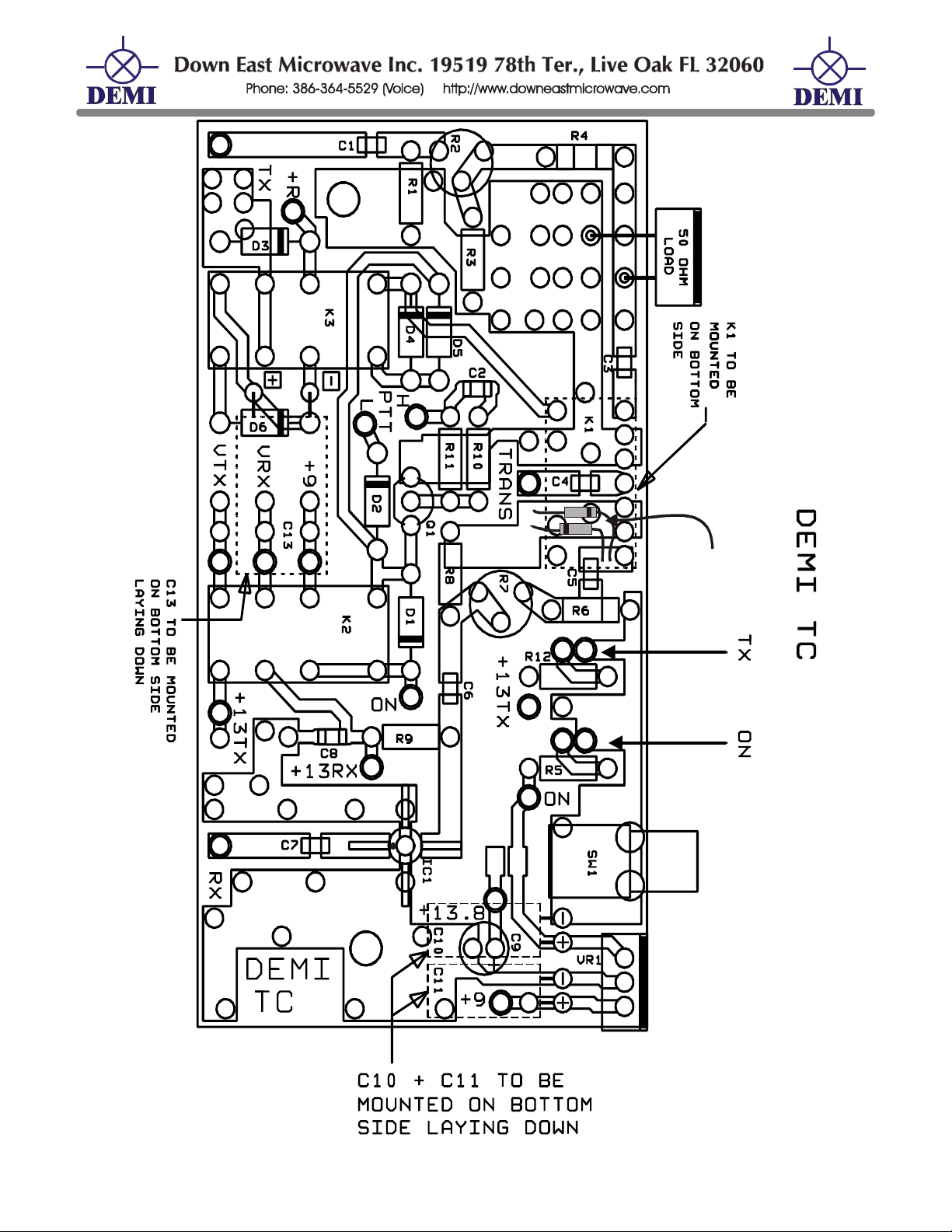
to install IC1, refer to the component placement to determine where it is installed along with its bias
resistor R9. Any low frequency MMIC may be used but select it for the correct amount of gain
required. Also consider the noise figure unless you have a RF LNA in the system. Select the
value of R9 for the MMIC to be used for 13.8VDC operation. To bypass the gain stage, install a
leaded 120pF capacitor in place of IC1. Keep the leads short.
The RXIF gain can be adjusted with R7. There should be approximately 20 dB of range.
With your system completely connected, R7 may be adjusted to an acceptable level determined by
your ear. For best results, keep the gain to a minimum. Only a slight noise increase should be
noticed by cycling the power switch of the transverter. If your “S” meter of your IF radio is at half
scale, you have lost half of the dynamic range of your system. For the same reasoning, adding the
gain stage and then adjusting the RXIF to maximum will degrade the dynamic range further.
(All functions mentioned may or may not be enabled in your transverter)
/Built/2304op.doc 4 Rev. A 1/14/08
Page 5

TXIF Drive Level and Adjustment.
The TXIF drive level adjustment (R2) has approximately 20 dB of range. Depending on the
configuration ordered, this adjustment range may not be acceptable. If so the fixed attenuator may
need to be installed, removed, or adjusted. If you wish to use less than 50 milliwatts of IF drive
power, install a short jumper wire in the R4 position and remove the large 50 ohm termination that
may be installed on the front panel. If you wish to use up to 2 watts, install R4 as shown with the
large 50 ohm termination. If you plan to use 1 - 10 watts of IF drive, install a 1pF capacitor in the
R4 position with the 50 ohm termination. If you need to experiment with other drive levels, any
combination of variable capacitor or resistor may be used in the R4 position. You may also adjust
the values of R1 and R3 as needed. Input power to the TXIF adjustment is dependent on the
attenuation installed on the C3 side of the K1 relay. The 50 ohm load resistor is designed to
handle 35 watts with proper heat sinking. When mounted to the front panel of the transverter, it
will not tolerate more than 10-12 watts reliably for a long period of time. You may experiment with
external heat sinking if you desire. External attenuation may also be used in the transceive path.
Remember that the added attenuation is also on the receive signal but may be overcome by the
additional gain of the RXIF gain stage. The level then may be adjusted with the RXIF adjustment.
Split Transmit and Receive or Common IF Configuration:
If you wish to use your transverter with separate TX and RX ports, first remove C3 and C5.
Then attach coax from the IF connectors to the corresponding TXIF and RXIF connections at the
C3 and C5 locations. If you are converting a split IF to a common IF, C3 and C5 may or may not
be already installed. Select the coax you wish to keep as the common and connect it to the
common input of K1.
PTT-H and PTT-L
The TC has the option of either using a PTT-H or PTT-L keying circuit. The PTT-H requires
+1.5 to +18VDC to activate it and will sink up to 2 mA. If using this circuit, be certain that the sink
current will not exceed your transceivers rating. The PTT-L circuit requires a connection to ground
to be activated. It is connected to the K1 relay and will source up to 25 mA to ground when keyed.
If this exceeds your transceivers rating you may modify the TC as shown in our design note DN0??
Found in our library on our web site or call for a copy.
PTT Keying Through the IF Coax:
Some transceivers such as certain models of the Yaesu FT290 supply a positive voltage on
it’s RF output connector during transmit or receive. This voltage may be used for keying the
transverter. After verifying or modifying your transceiver for this function, the transverter may have
the option installed. Select a choke of 1.0 µh or larger and install it in the L1 position of the TC.
Then connect a short wire jumper from the DC side of L1 to the PTT-H connection. When the
transceiver is keyed, the voltage in the coax will key the PTT-H of the transverter. This is the most
fool proof connection of the PTT line that can be made with any transceiver and is highly
recommended by DEMI.
If the PTT-L connection is connected to the PTT connector, it will not affect the operation of
the system. Just do not key both lines at the same time! If you will never use it, it may be
disconnected and the external connector may be used for any other auxiliary connections.
+DC Switching Functions:
/Built/2304op.doc 5 Rev. A 1/14/08
Page 6

Relay K2 controls all of the +DC switching functions in the transverter. One side of the relay
switches the raw +DC supply voltage to the transverter and the other side switches the regulated
+9 volts. There are extra connection holes on the PCB if you require any additional switched
voltage. Be sure not to exceed the 1.5 amp limit on the 9 volt regulated supply. The transverter’s
current drain is listed on its configuration page and allow for some overhead when the oscillator is
not warmed up.
The switched voltages may be used for external LNA’s, switching circuits for power
amplifiers or relays. You may need to add an extra hole for a connector if the AUX connector is
used. Be sure to fuse any external connections. The relay’s contacts (K2) are rated for 3 amps.
24 Volt Relay Driver:
The TC is designed with a 24 Volt relay driver. A brief explanation of the circuit is as
follows. When the TC is in the receive mode, a 330 µF capacitor is charged to the raw input
voltage of the transverter (12-14 VDC). When the PTT circuit is activated, K3 switches this
charged capacitor in series with the TXON voltage and outputs a brief spike of 24-28 VDC at the
+R connection on the TC board. Depending on the current drain of the connected circuit (or relay),
the charged capacitor bleeds off down to the raw input voltage of the transverter. The spike is
enough to energize most SMA relays and the raw transverter voltage is enough to keep the relay
energized. This circuit will not work with all relays but will operate with all relays supplied by DEMI
in the optional WTR kit. If you wish to use a relay with a higher current drain, the 330 µF capacitor
may be increased. Just be sure that the relay being used will stay energized with +12 VDC. This
circuit will not operate latching relays unless additional circuitry is installed.
PLEASE NOTE!
Even though this connection will bleed down to the raw voltage of the
transverter, the circuit should never be used on any electronic circuit that will not tolerate a
+28VDC input!
It will damage most +12VDC circuits. It will also not operate any circuit requiring
voltage greater than the transverter’s supply voltage other than a relay.
If a switched +VDC is required, move the wire from the +R connection (if installed) to either
the +VTX, +RX, +9, +13RX, +13TX, or +13.8SW. Refer to the schematic for their functions.
RF Sensing Transverter Keying
The TC is not designed to be a RF sensed switch. It has 3 relays and it may be connected
to external mechanical relays. If any RF sensing scheme is added to the circuit, it will cause
excessive relay chatter that will not only ware out the relays prematurely, but could cause other
failures to external preamplifiers and or power amplifiers if used in your system. RF sensing
circuits are not recommended with any circuit the contain mechanical relays at RF frequencies!!
/Built/2304op.doc 6 Rev. A 1/14/08
Page 7
DEM TC Component List
C1 0.01 µF C10 2.2 µF elect.
C2 0.01 µF C11 2.2 µF elect. R1 220 Ω R10 5.1KΩ
C3 0.01 µF C13 330 µF elect.
C4 0.01 µF
C5 0.01 µF
C6 0.01 µF
C7 0.01 µF
C8 0.01 µF
C9 100 µF elect. L1 1.0 µh o R8 220 Ω
n To by-pass IF gain stage, install 120pF in place of IC1.
o L1 is used with transceivers that have + DC voltage on RF line during transmit
p Depending on the drive level used, R4 may be replaced with a short, a 1pF capacitor, or a
variable capacitor. See text for description.
D1 -D6 1N4000
IC 1 MAR6 n
K1 G6Y relay
K2 G5V relay
K3 G5V relay R7 1K pot
Q1 PN2222
R2 1K pot
R3 220 Ω R12 330 Ω
R4 220 Ω p
R5 1K Ω
R6 220 Ω 50 Ω load
R9 330 Ω
R11 5.1KΩ
2 - Red LED
VR1 78S09
1 ρF p
/Built/2304op.doc 7 Rev. A 1/14/08
Page 8
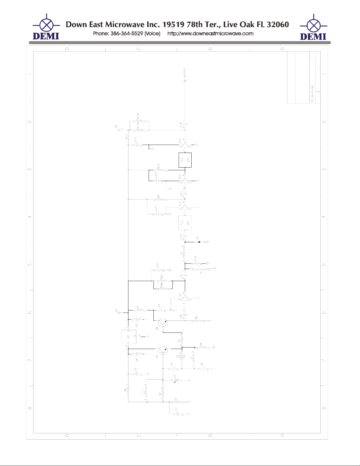
DEM MICROLO
Microwave Transverter Local Oscillator
Description and Operation:
The MICROLO is used in all of DEMI’s line of microwave transverters (2304 and up) as the
base frequency oscillator. Depending on the model of transverter you have, the table below will
provide crystal information and multiplication factors for all. The frequencies listed in the Model
column are the standard “Weak Signal” RF operating frequencies. Your transverter may be
configured for other RF and IF frequencies than listed below but will be indicated on the
configuration page of the main transverter document.
Model Crystal LO Output Frequency
and Output Power
2304-144 MHz. 180.000 MHz. 1080.000 MHz. +3dBm X2 2160.000 MHz.
3456-144 MHz. 184.000 MHz. 1104.000 MHz. +3dBm X3 3312.000 MHz.
5760-144 MHz. 187.200 MHz. 1123.200 MHz. +3dBm X5 5616.000 MHz.
10368-144 MHz. 189.333 MHz. 1136.000 MHz. +3dBm X9 10224.000MHz
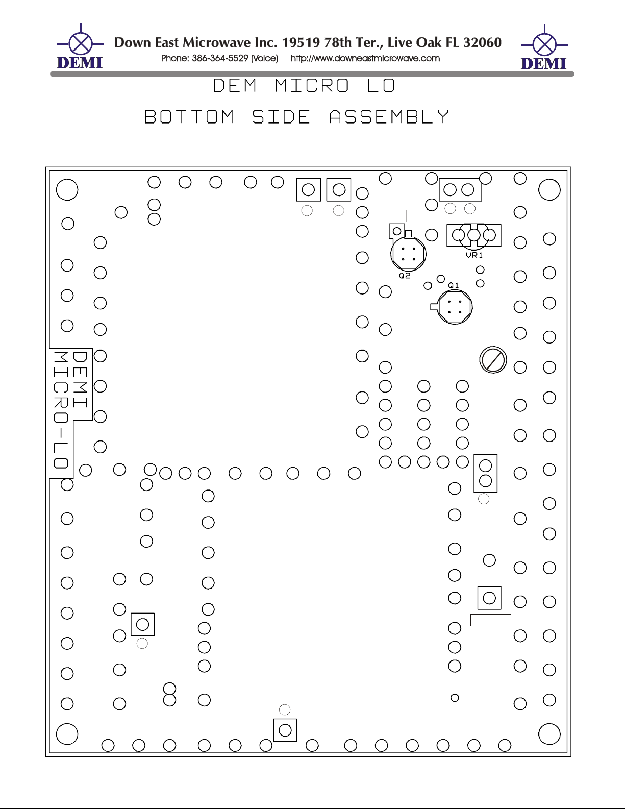
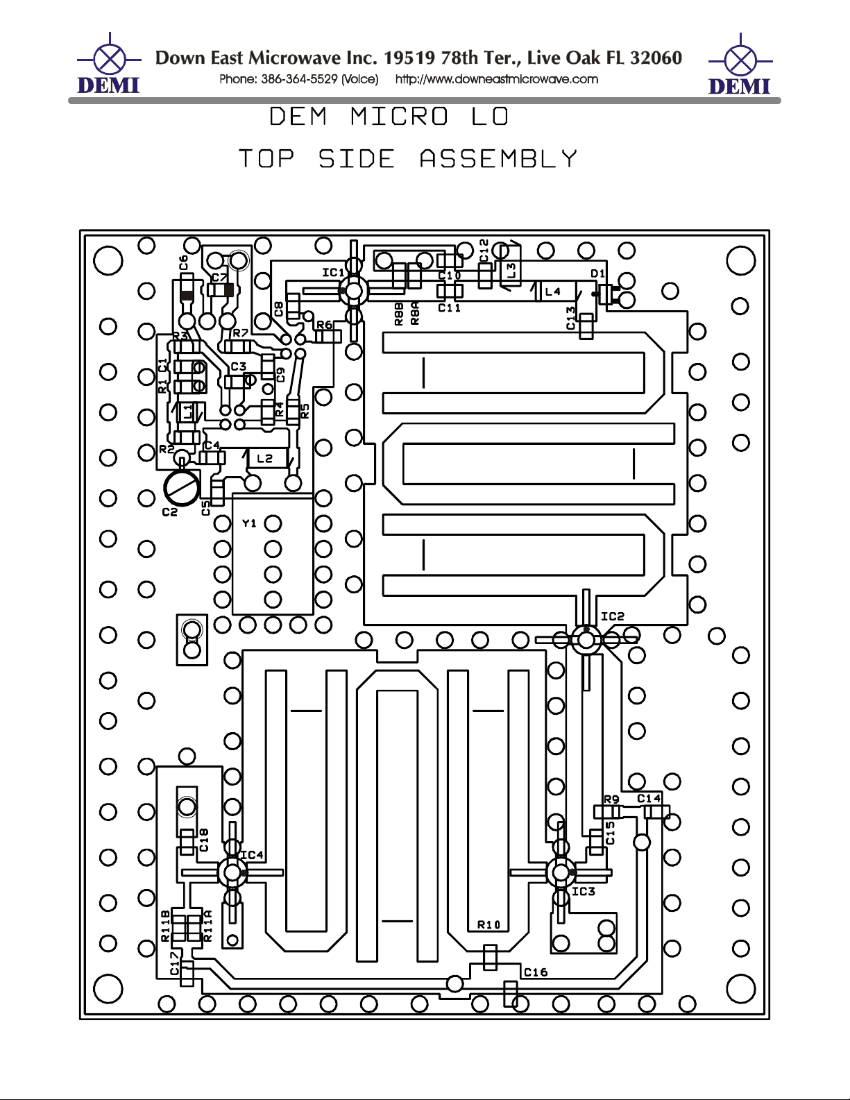
If you encounter any problems relating to the MICROLO, refer to the DC checklist, and with
a voltmeter, find the test points on the component placement and schematic. Then proceed to
verify all six test points. All voltages are referenced to ground. The MICRO-LO is supplied by the
+9 VDC voltage from the TC board. Verify all +9VDC connections first.
Voltage test points
Test junction point Voltage Test junction point Voltage
Input of IC1 - IC4
Junction of Q1 - C3
Junction of R5 - Q2
2.0V ± 0.75
5V ± 0.2
0.8V ± 0.3
Output of IC1 - IC4
Junction of R1-C1
TP1 > 0.7V
If troubleshooting the MICROLO, be sure the voltage at TP1 is peaked by adjusting C2. This
will assure the best performance of the MICROLO. If you have a frequency meter, the frequency
may also be adjusted with C2. Although this is an acceptable way of “Netting” the frequency, any
adjustment other than a voltage peak at TP1 may result in a oscillator that will not start when cold,
drift, or have low output power.
If any of the test voltages cannot be obtained on IC1 - IC4, understand that MMICs may
sometimes operate out of specification. The important thing in troubleshooting is that all MMICs
draw current when working correctly and have something other than the supply voltage or a short
to ground on both Input and output.
Multiplication Xverter LO
Frequency
5V± 1 V
1.8V± .5
/Built/2304op.doc 8 Rev. A 1/14/08
Page 9
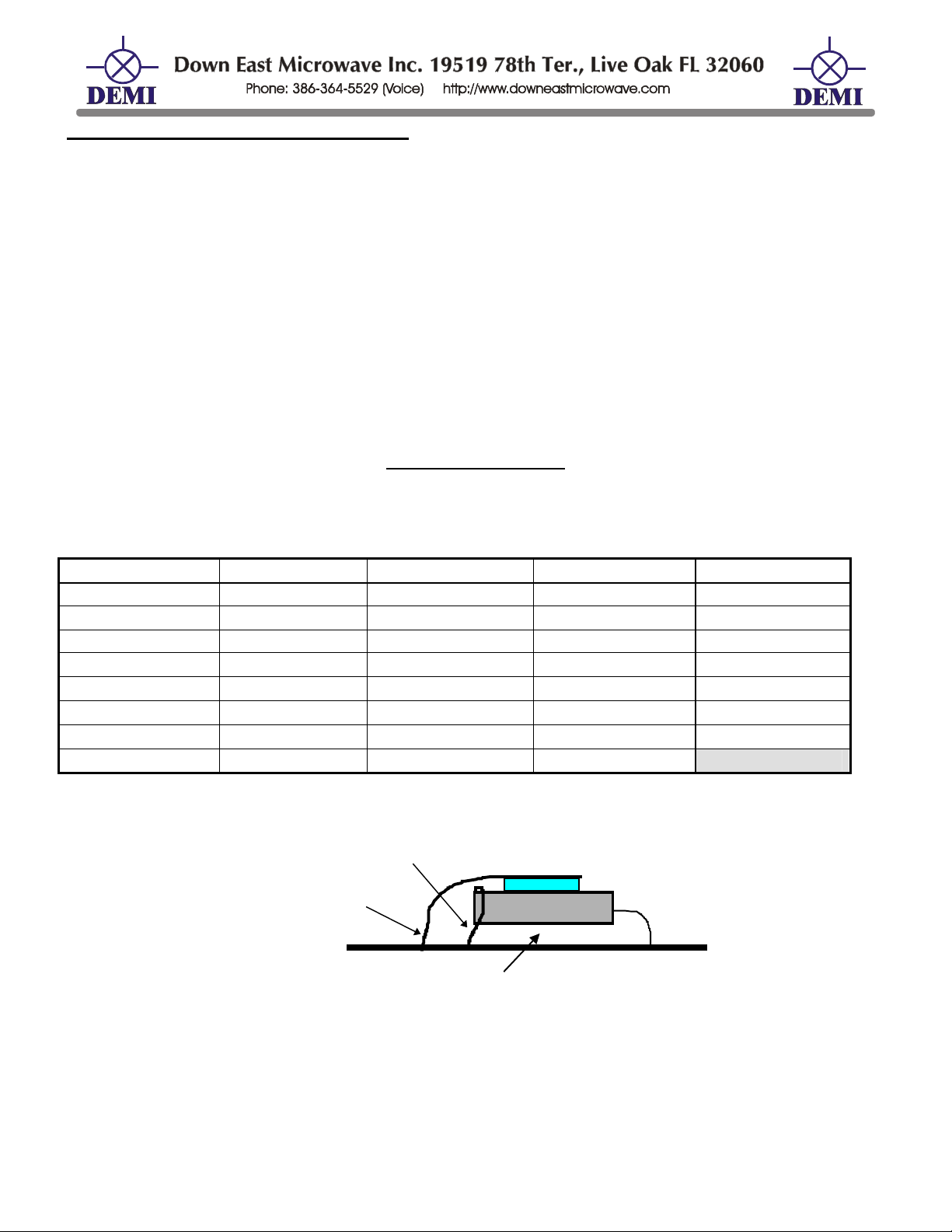
Changing the Crystal in the MICROLO:
If you decide to change the operating frequency of your transverter, install the new crystal
exactly the same way as the original crystal. Before installing the Thermistor as shown in figure 1.,
verify that the MICROLO operates with the new crystal first. If the voltage peaks and the frequency
can be “Netted”, attach the Thermistor and ground wire. To assure frequency stability over time,
allow the LO to operate for 1 hour with the Thermistor in place before adjusting the final frequency.
In real time operation total warm-up should be no more than 5 minutes maximum after the first
hour of operation.
After a new crystal installation and a minimum of a 1 hour “Burn-In”, you may encounter
difficulty netting the frequency. If so, please consult our Design Note # 016 found in the Down East
Microwave web site library or call for a copy. It reviews a procedure that requires a circuit
modification and adding a chip capacitor.
MICROLO Parts List
All capacitors are chips and are pF unless otherwise noted. White Band is Positive on 1.0 µF. All
resistors are in ohms. The coils are formed using #24 enamel wire.
C1 0.01µF C10 0.1µF
D1 HSMS2800 R3 1K VR1 78L05
C2 1-8 Piston C11 22 L1 3T 1/8" ID R4 100 Y1 CRYSTAL
C3 0.01µF
C12 15
L2 0.1µH molded
R5 51 IC1 MAR-3
C4 18 C13 15 L3 6T 1/8" ID R6 100 IC2 MAR-1
C5 22
C6 1.0 µF
C14 0.1µF
C15 22 Q1 2N5179 R8A,B 220 IC4 MAR-3
C7 1.0µF C16 0.1µF
C8 0.01µF C17 0.1µF
C9 0.1µF
C18 22 R2 1K R11A, B 220
L4 4T 1/8" ID R7 100 IC3 MAR-1
Q2 2N5179 R9 180 PTC-Thermistor
R1 560 R10 180 Micro-LO PCB
Solder Wire to
Ground and Xtal
9Volt
Supply
1/16” Space between PCB and Xtal
CRYSTAL
Figure 1. Crystal and Thermistor Installation details.
/Built/2304op.doc 9 Rev. A 1/14/08
Page 10
TX
RX
8
D
7
D
/Built/2304op.doc 10 Rev. A 1/14/08
Page 11
ADJUST
J
TX
X
D
7
D
8
XX
TX
RX
Caution:
Lift Leads
RX AD
LEDS
UST
/Built/2304op.doc 11 Rev. A 1/14/08
Page 12
MICROLO
/Built/2304op.doc 12 Rev. A 1/14/08
Page 13
X
X
X
3
X
X
X
6
4
TP1
5
7
X
2
1
/Built/2304op.doc 13 Rev. A 1/14/08
OUTPUT
Page 14
+9 V
X
X
V
9
+
+
+
X
X
+9 V
X
OUTPUT
+9 V
X
V
9
X
+
/Built/2304op.doc 14 Rev. A 1/14/08
Page 15
HPA Section
+LO
+
C27
CR-2
C15
8
2
RX IF
+
C26
C6
U1
3
R2
5
4
C25
+
C24
R13
C22
C23
C21A
Q1
C30
TX HIGH
R15
TX
C29
U6
U7
C28
C21B
TX LOW
R9
C16
R10
C17
C20
R11
R12
C19
+TX
R16
TX IF
C7
+RX
+LO
CR-1
U2
R4
C5
R7
C11 C12
C4
U4 U5
R3
C2
R8
R2
C3
R1
U1
C1
RX
C14
LO IN
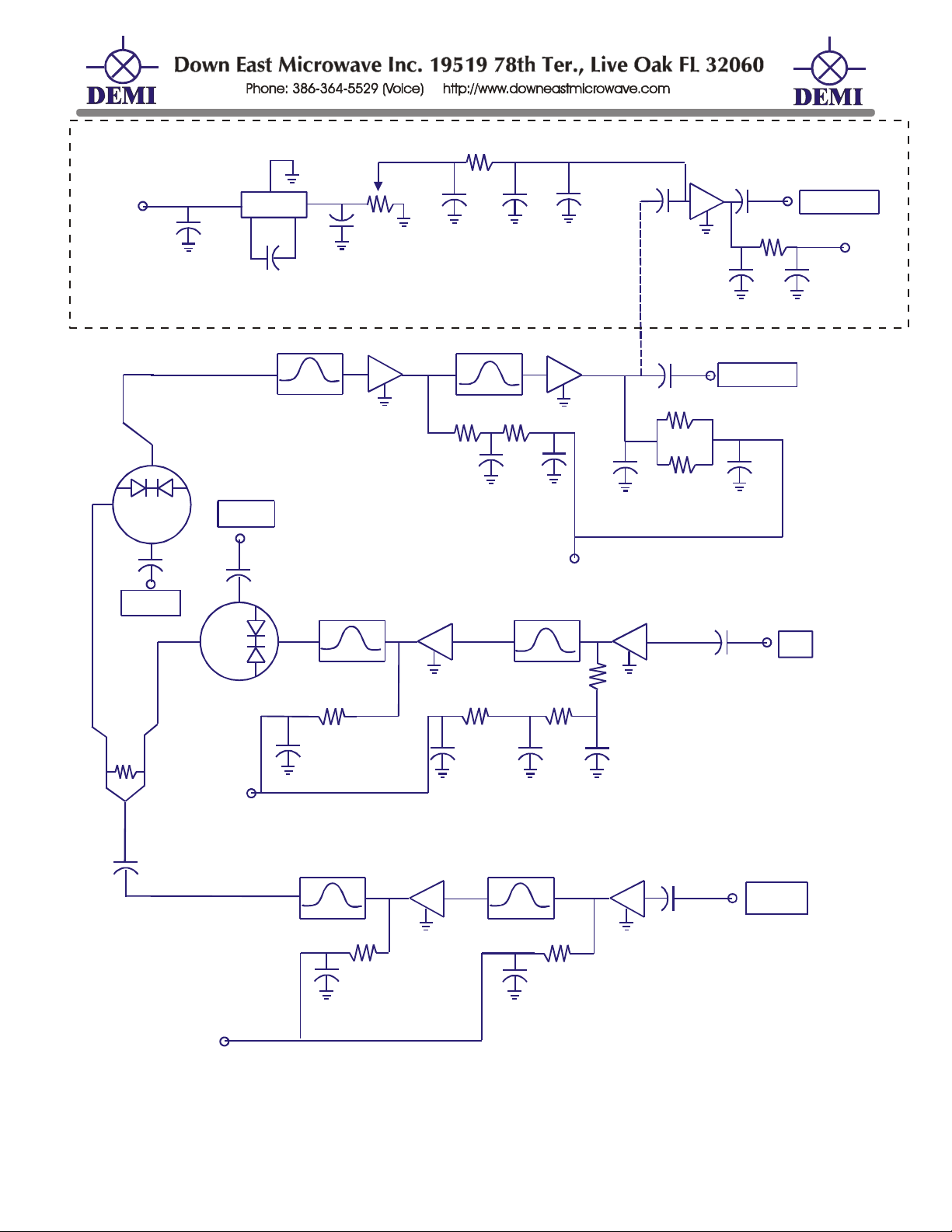
2304-144 TRANSVERTER SCHEMATIC
/Built/2304op.doc 15 Rev. A 1/14/08
Page 16
 Loading...