


Chapter 3 Intrinsically Safe Fieldbus Applications
This chapter provides information about fieldbus applications that provide
Intrinsically Safe (IS) power to fieldbus devices located in hazardous areas. The
Pepperl+Fuchs FieldConnex® Fieldbus Power Hub and FieldConnex® FieldBarrier
provide Intrinsically Safe power for both Intrinsically Safe – entity applications and
FISCO (Fieldbus Intrinsically Safe COncept)applications. Refer to the
Pepperl+Fuchs (P+F) documentation and/or visit the DeltaV website
(www.easydeltav.com) and follow the links for additional information on these
products.
Ensure that the fieldbus devices and all components used in the application are rated
and certified for IS applications.
Warning In any hazardous area installation it is important to read and follow the device
manufacturer's design and installation documents. Failure to follow the
documentation could result in an unapproved and unsafe application.
Additionally, in hazardous locations follow your plant's procedures for making
the area safe during installation and maintenance operations.
DC Power Considerations for Intrinsically Safe Applications
The basic IS application uses the Fieldbus Power Hub with the FBPS-1.500 Isolated
Power Supply Module to provide power to field devices connected through one or
more IS Field Barriers.
The available power to a field device depends on the length and resistance
characteristics of the fieldbus cable to each Field Barrier and the output characteristics
of the Field Barrier to the field device. T
make the example calculations in Table 6 on page 53
maximum distance for a given load on the Fieldbus Power Hub for applications using
Intrinsically Safe Fieldbus Applications 51
he P+F segment calculator tool was used to
. The calculations show the

2, 3, and 4 Field Barriers to connect up to 16 field devices. The calculations are based
on the following assumptions:
Power Supply Voltage = 28.0 VDC @ 500 mA
Minimum Voltage at last Barrier = 16 VDC
Minimum Device Voltage = 9 VDC
Maximum Voltage drop from cable to last barrier = 12 VDC
Redundant H1 connected at a load of 24 mA
Each device has an average load of 20 mA
Ensure that any device load on a spur output from the field barrier is 30 mA or
less
Each Barrier spur has a maximum of one device connected.
Barriers and Devices are connected on one end of the cable and the Fieldbus
Power Hub is connected on the other end of the cable
Each device is connected on a 10 meter maximum spur cable.
Barriers are inter-connected on a 10 meter maximum trunk cable.
Fieldbus Type A 18 AWG cable @ 22 ohms/km (44 ohms/km loop resistance) at
22
°C
Maximum Distance (km) = (Allowed Loop V drop / Loop current) / Loop
resistance per km
There will be different restrictions and limitations on your segment if these
assumptions do not hold for your segment layout. If your devices average more than
20 mA per device, reduce the maximum cable length indicated in the table for that
number of devices or reduce the number of devices on the segment. Refer to the
device documentation for information on current requirements for the device.
When referring to Table 6, remember the Redundant Series 2 H1 card requires 24 mA
of fieldbus power.
The loads listed are the normal loads required by the barriers and devices. However,
the numbers take into account the additional current required if the smallest load on
one barrier is accidentally shorted (during a maintenance operation) to protect the
segment from being affected.
If these assumptions do not properly represent your specific application, it is
recommended that a calculation be completed to verify that the segment design
adequately meets your process requirements.
52 Fieldbus Installations in a DeltaV Digital Automation System

Table 6 Distance per Load on the Fieldbus Power Hub with Field Barriers
Number of
Devices / Load
(mA)
1 / 20 1875 75 1850 103 1575 131
2 / 40 1850 94 1625 123 1400 151
3 / 60 1675 112 1425 143 1250 171
4 / 80 1500 130 1275 161 1125 192
5 / 100 1325 149 1150 180 1025 211
6 / 120 1200 163 1050 198 950 231
7 / 140 1000 184 975 218 875 250
8 / 160 1000 208 900 237 800 267
9 / 180 N/A N/A 825 256 750 288
10 / 200 N/A N/A 775 274 700 307
11 / 220 N/A N/A 725 290 650 325
12 / 240 N/A N/A 725 316 625 346
Distance (meters) and Power Supply Load (mA)
Max
Distance
with 2
Barriers
Power Supply
Load
with 2 Barriers
Max
Distance
with 3
Barriers
Power Supply
Load with 3
Barriers
Max
Distance
with 4
Barriers
Power Supply
Load with 4
Barriers
13 / 260 N/A N/A N/A N/A 600 366
14 / 280 N/A N/A N/A N/A 550 378
15 / 300 N/A N/A N/A N/A 525 395
16 / 320 N/A N/A N/A N/A 525 422
16 / 340 N/A N/A N/A N/A 475 429
16 / 360 N/A N/A N/A N/A 425 433
Fieldbus Power Hub
Refer to “Pepperl+Fuchs Fieldbus Power Hub for Redundant Fieldbus Power” on
page 39 for information on the Fieldbus Power Hub system.
Intrinsically Safe Fieldbus Applications 53

Field Barrier for Intrinsically Safe Applications in Hazardous Locations
The Field Barrier connects up to four field devices located in hazardous locations to
the fieldbus segment and provides short circuit protection to each device. Ensure that
any device load on a spur output from the field barrier is 30 mA or less. Figure 11
shows a Field Barrier for four devices.
S1 terminator switch
Spur connections
Spur connections 1-4
10+11 13+1412s 16+1715s 19+18s 20 21s
ON
S1 BUS
TERM.
OFF
PWR
_
1
2
3
4
Figure 11 Field Barrier for Four Devices
1B 2B
14
3+ 4-
5s 6s
Trunk connections
7
- 8+
Trunk connections 1-2
Installing and Connecting the Fieldbus Power Hub
Refer to “Installing and Connecting the Fieldbus Power Hub” on page 46 for
information on installing the Motherboard, Power Supply Modules, and Diagnostics
Modules and connecting the Fieldbus Power Hub.
54 Fieldbus Installations in a DeltaV Digital Automation System

Installing and Connecting the Field Barrier
Refer to Figure 11 on page 54.
¾ To install and connect a Field Barrier
1. Securely attach the Field Barrier at the desired location.
2. For the Trunk segment connection: connect the positive (+) segment wire to the
positive, connect the negative (-) segment wire to the negative, and connect the
segment shield (S) to the S.
3. Remove the shorting jumpers (1B, 2B) so that the Trunk (S) shields are isolated
from, not connected to the Field Barrier case.
4. For each device connection: connect the positive (+) spur wire to the positive,
connect the negative (-) spur wire to the negative, and connect the shield wire (S)
to the S.
5. The Spur (S) shields must be connected to the Field Barrier case and isolated at
the device in the field. The best way to ground the output shields at the barrier is
with a mechanical connection through a metal gland or bar at the barrier.
6. If this Field Barrier is at the end of the segment, the terminator switch S1 should
be in the On position. If this is not the end of the segment, ensure that the
terminator switch S1 is in the Off position.
7. If the segment continues and connects to another Field Barrier, continue the
Trunk segment by connecting the Trunk Out connections to the next Field
Barrier and proceed with steps 3, 4, and 5.
8. Ensure that the shorting jumpers (1B, 2B) are removed on all Field Barriers, so
that the Trunk (S) shields are isolated from not connected to the Field Barrier
case.
9. If this Barrier is the end of the segment, ensure that the terminator switch S1 is
in the On position.
Verifying the Installation
Refer to “Verifying the Installation” on page 48.
Intrinsically Safe Fieldbus Applications 55
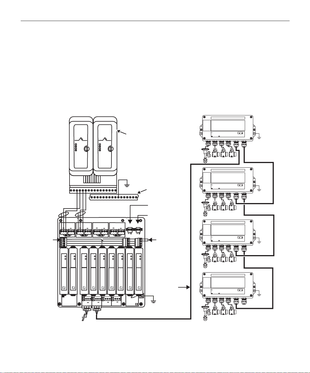
Intrinsically Safe Application Example
A
Figure 12 shows an application that uses a redundant pair of Series 2 H1 cards with
redundant fieldbus power and intrinsic safety barrier protection for 16 devices on a
long (0.5 km) trunk cable. If a failure occurs on an H1 card, a 24 V power supply, or a
fieldbus power supply, the segments continue to operate as expected. A status
indication on connected alarms alerts the operator that an error has occurred. It is
assumed that the application design follows the criteria specified in “DC Power
Considerations for Intrinsically Safe Applications” on page 51. Therefore, if a short
occurs when a device is installed or removed from the segment, only that device is
affected; the rest of the segment is unchanged.
Series 2
Power/Active
Error
Port 1
Port 2
Series 2
Power/Active
Error
Port 1
Port 2
Redundant
Series 2 H1
cards
Field Barrier
PEPPERL+FUCHS
F2D0-FB-E
x4
TERMINATOR
ON
T - OFF
OFF
GND
Fieldbus
H1
Fieldbus
H1
T - OFF
GND
Carrier
Field Barrier
PEPPERL+FUCHS
F2D0-FB-E
x4
TERMINATOR
ON
OFF
GND
shield bar
Port 1
Port 2
Primary
24 VDC
Secondary
24 VDC
SEC
PWR
Alarm
Field Barrier
PEPPERL+FUCHS
F2D0-FB-E
x4
TERMINATOR
ON
T - OFF
OFF
GND
jumper
PWR
ERR
HD2
FBPS-
1.500
larm
contacts
Host A
Host A
Host A
Host B
SEG1
S
S ---
+
ON
PWR
ERR
HD2
FBPS-
1.500
Host B
SEG2
S
S ---
+
+
+
OFF
OFF
ON
Alarm
Diagnostic Bus
PWR
PWR
ERR
HD2
FBPS-
1.500
PWR
ERR
ERR
HD2
HD2
FBPS-
FBPS-
1.500
1.500
Host A
Host B
Host B
SEG3
S
S
S ---
+
+
OFF
ON
ON
PWR
PWR
ERR
ERR
HD2
HD2
DMB
FBPS-
1.500
PRI
SEG4
PWR
S ---
+
+
OFF
PWR
PWR
ERR
ERR
HD2
HD2
FBPS-
FBPS-
1.500
1.500
T - ON
PEPPERL-FUCHS
Fieldbus Power Hub
Fieldbus Motherboard
OFF
+
Segment 1
SOFF
+
SOFF
S
+
Segment 2
Segment 3
+
Segment 4
FieldConnex
SOFF
T - ON
with drain wire
GND
0.5 km Cable
Shielded pair
Field Barrier
PEPPERL+FUCHS
F2D0-FB-E
x4
TERMINATOR
ON
OFF
GND
Figure 12 IS Application with 16 Devices Using the Fieldbus Power Hub and Field Barrier
56 Fieldbus Installations in a DeltaV Digital Automation System
 Loading...