

Page 1
Delta Standard Compact Drive
MS300 Series User Manual
Page 2
PLEASE READ PRIOR TO INSTALLATION FOR SAFETY.
AC input power must be disconnected before any wiring to the AC motor drive is made.
Even if the power has been turned off, a charge may still remain in the DC-link
DANGER
capacitors with hazardous voltages before the POWER LED is OFF. Please do not
touch the internal circuit and components.
There are highly sensitive MOS components on the printed circuit boards. These
components are especially sensitive to static electricity. Please do not touch these
components or the circuit boards before taking anti-static measures.
Never reassemble internal components or wiring.
Ground the AC motor drive using the ground terminal. The grounding method must
comply with the laws of the country where the AC motor drive is to be installed.
DO NOT install the AC motor drive in a place subjected to high temperature, direct
sunlight and inflammables.
Never connect the AC motor drive output terminals U/T1, V/T2 and W/T3 directly to the
CAU TION
AC mains circuit power supply.
The rated voltage of the AC motor drive must be 115V for 110V models, 240V for
230V models, and 480V for 460V models.
Only qualified persons are allowed to install, wire and maintain the AC motor drives.
Even if the 3-phase AC motor is stop, a charge may still remain in the main circuit
terminals of the AC motor drive with hazardous voltages.
If the AC motor drive is stored in no charge condition for more than 3 months, the
ambient temperature should not be higher than 30°C. Storage longer than one year is
not recommended, it could result in the degradation of the electrolytic capacitors.
Pay attention to the following when transporting and installing this package (including
wooden crate, wood stave and carton box)
1. If you need to sterilize, deform the wooden crate or carton box, please do not
use steamed smoking sterilization or you will damage the VFD.
2. Please use other ways to sterilize or deform.
3. You may use high temperature to sterilize or deform. Leave the packaging
materials in an environment of over 56°C for 30 minutes.
Type of electrical supply system (3WYE) to which the drive shall be connected.
NOTE
For a detailed explanation of the product specification, the cover or the safety shields will be disassembled, as
described in graphic mode. As for the product in operation, please install the top cover and wiring correctly
according to the provisions. Refer to the manual operation to ensure safety.
The figures in this instruction are only for reference, they may be slightly different from the one you have, but it will
not affect your customer rights.
The content of this manual may be revised without prior notice. Please consult our distributors or download the
latest version at
http://www.deltaww.com/services/DownloadCenter2.aspx?secID=8&pid=2&tid=0&CID=06&itemID=060101&typeID
=1&downloadID=&title=&dataType=&check=0&hl=en-US
I
Page 3

Table of Contents
CHAPTER 1 INTRODUCTION ................................................................................................. 1-1
1-1 Nameplate Information................................................................................................1-2
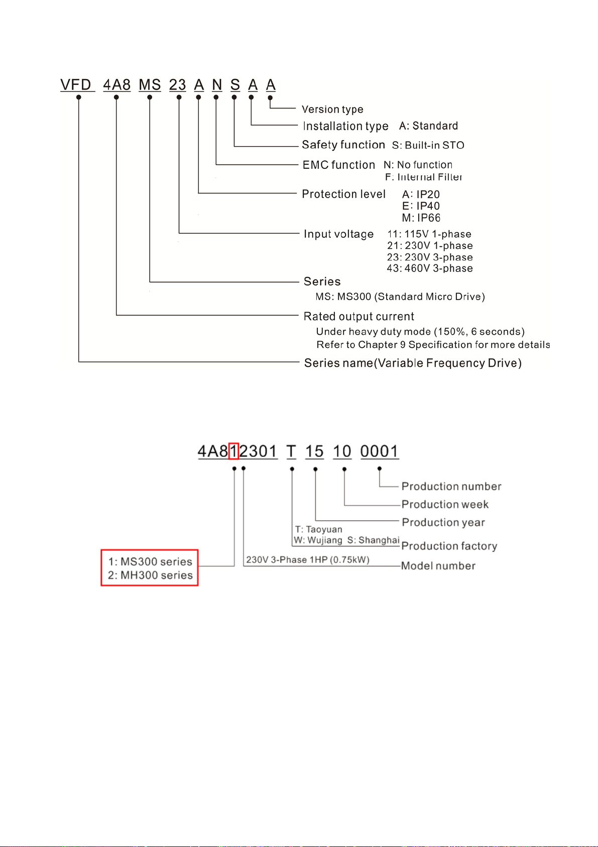
1-2 Model Name...............................................................................................................1-3
1-3 Serial Number..............................................................................................................1-3
1-4 RFI Jumper..................................................................................................................1-4
CHAPTER 2 DIMENSION ........................................................................................................ 2-1
Frame A……………………………………………………..……………………………………2-1
Frame B……………………………………………………………..……………………………2-2
Frame C……………………………………………………………..……………………………2-3
Frame D…………………………………………………………..………………………………2-4
Frame E…………………………………………………………..………………………………2-5
Frame F…………………………………………………………..………………………………2-6
Digital Keypad…………..……………………………………………………………………….2-7
CHAPTER 3 INSTALLATION ................................................................................................... 3-1
CHAPTER 4 WIRING ............................................................................................................... 4-1
4-1 Wiring...........................................................................................................................4-3
4-2 System Wiring Diagram...............................................................................................4-6
CHAPTER 5 MAIN CIRCUIT TERMINALS ............................................................................ 5-1
5-1 Main Circuit Diagram....................................................................................................5-4
5-2 Main Circuit Terminals..................................................................................................5-5
Frame A………………..………………………………..……………………………………5-6
Frame B………..………………………………………………..……………………………5-7
Frame C………..………………………………………………..……………………………5-8
Frame D………...……………………………………………….……………………………5-9
Frame E…………...…..………………………………………….…………………………5-10
Frame F………….…….……………………………………….……………………………5-11
CHPATER 6 CONTROL TERMINALS ..................................................................................... 6-1
CHAPTER 7 OPTIONAL ACCESSORIES ............................................................................... 7-1
7-1 All Brake Resistors and Brake Units Used in AC Motor Drives...................................7-2
7-2 Non-fuse Circuit Breaker............................................................................................7-5
7-3 Fuse Specification Chart ...........................................................................................7-7
7-4 AC/DC Reactor...........................................................................................................7-9
7-5 Zero Phase Reactor.................................................................................................7-23
7-6 EMC Filter.................................................................................................................7-26
7-7 EMC Shield Plate....................................................................................................7-30
7-8 Capacitive Filter.........................................................................................................7-33
II
Page 4

7-9 Conduit Box…..........................................................................................................7-35
7-10 Fan Kit.....................................................................................................................7-43
7-11 Keypad Panel Mounting ……..................................................................................7-44
7-12 DIN-Rail Mounting...................................................................................................7-45
7-13 Mounting Adapter Plate………………………………….……………………………7-47
CHAPTER 8 OPTION CARDS .................................................................................................. 8-1
8-1 Option Card Installation................................................................................................8-2
8-2 CMM-MOD01 Modbus/TCP Option Card.....................................................................8-7
8-3 CMM-PD01 PROFIBUS Option Card.........................................................................8-10
8-4 CMM-DN01 DeviceNet Option Card..........................................................................8-12
8-5 CMM-EIP01 Modbus TCP/EtherNet IP Option Card..................................................8-15
8-6 CMM-COP01 CANopen Option Card.........................................................................8-18
8-7 EMM-BPS01 Back-up Power Supply Card................................................................8-20
CHAPTER 9 SPECIFICATION .................................................................................................. 9-1
9-1 115V Series…………………………….......................................................................9-2
9-2 230V Series………………………………......................................................................9-3
9-3 460V Series………………………………......................................................................9-5
9-4 Environment for Operation, Storage and Transportation……………………...............9-8
9-5 Derating of Ambient Temperature and Altitude……………………................................9-9
CHAPTER 10 DIGITAL KEYPAD ........................................................................................... 10-1
CHAPTER 11 SUMMARPY OF PARAMETERS SETTINGS .................................................. 11-1
CHAPTER 12 DESCRIPTION OF PARAMETER SETTINGS .......................................... 12-00-1
12-1 Description of Parameter Settings……………………..……………………………12-00-1
12-2 Adjustment & Application…………………………………………………………….. 12.2-1
CHAPTER 13 WARNING CODES .......................................................................................... 13-1
CHAPTER 14 ERROR CODES .............................................................................................. 14-1
CHAPTER 15 CANOPEN OVERVIEW ................................................................................... 15-1
CHAPTER 16 PLC FUNCTION APPLICA TIONS ................................................................... 16-1
CHAPTER 17 SAFETY TORQUE OFF FUNCTION………………………..…………………….17-1
17-1 The Drive Safe Function Failure Rate.....................................................................17-2
17-2 Safe Torque Off Terminal Function Description......................................................17-2
17-3 Wiring Diagram.......................................................................................................17-3
17-4 Parameter...............................................................................................................17-4
17-5 Operating Sequence Description............................................................................17-4
17-6 Error Code..................................................................................................17-6
Application
Control Board: V 1.0
III
Page 5

[ This page intentionally left blank ]
IV
Page 6

Chapter 1 IntroductionMS300
Chapter 1 Introduction
1-1 Nameplate Information
1-2 Model Name
1-3 Serial Number
1-4 RFI Jumper
1-1
Page 7

Chapter 1 Introduction MS300
After receiving the AC motor drive, please check for the following:
1. Please inspect the unit after unpacking to ensure it was not damaged during shipment. Make sure
that the part number printed on the package corresponds with the part number indicated on the
nameplate.
2. Make sure that the mains voltage is within the range as indicated on the nameplate. Please install
the AC motor drive according to this manual.
3. Before applying the power, please make sure that all devices, including mains power, motor, control
board and digital keypad, are connected correctly.
4. When wiring the AC motor drive, please make sure that the wiring of input terminals “R/L1, S/L2,
T/L3” and output terminals”U/T1, V/T2, W/T3” are correct to prevent damage to the drive.
5. When power is applied, select the language and set parameters via the digital keypad (KPMS-LE01).
When executing a trial run, please begin with a low speed and then gradually increase the speed
until the desired speed is reached.
1-1 Nameplate Information
1-2
Page 8
1-2 Model Name
Chapter 1 IntroductionMS300
1-3 Serial Number
1-3
Page 9
Chapter 1 Introduction MS300
1-4 RFI Jumper
(1) In the drive there are Varistor / MOVs, which are connected from phase to phase and from phase to
ground, to protect the drive against mains surges or voltage spikes.
Because the Varistors / MOVs from phase to ground are connected to ground via the RFI jumper, the
protection will be ineffective when the RFI jumper is removed.
(2) In the models with built-in EMC filter the RFI jumper connects the filer capacitors to ground to form a
return path for high frequency noise to isolate the noise from contaminating the mains power.
Removing the RFI jumper strongly reduces the effect of the buiolt-in EMC filter.
(3) Although a single drive complies with the international standards for leakage current, an installation
with several drives with built-in EMC filter can trigger the RCD. Removing the RFI jumper helps, but
the EMC performance of each drive would is no longer guaranteed.
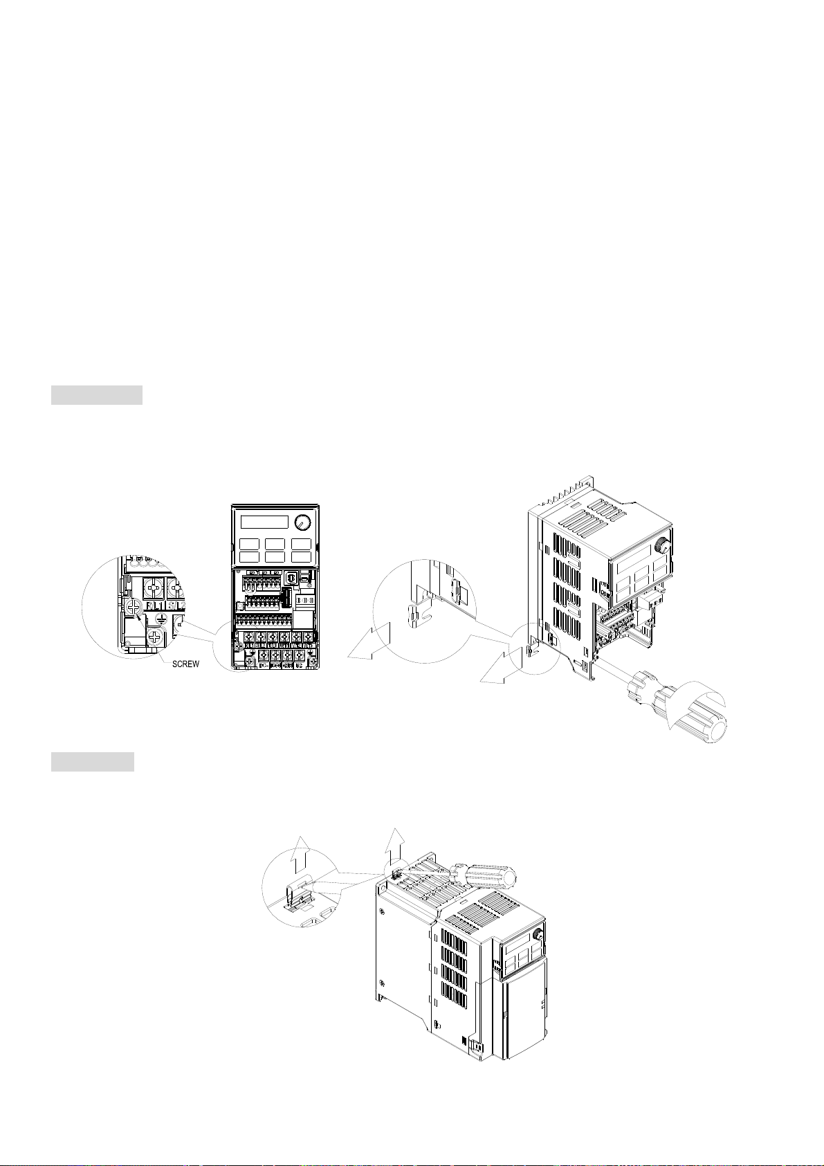
Frame A~F Screw Torque: 4~6 kg-cm / [3.5~5.2 lb-in.] / [0.39~0.59 Nm]
Loosen the screw and remove the RFI Jumper (as shown below). Fasten the screw again after the RFI
Jumper is removed.
Frame B~F (model with built-in EMC filter)
Remove the RFI Jumper with a screwdriver (as shown below).
1-4
Page 10
Chapter 1 IntroductionMS300
Isolating main power from ground:
When the power distribution system of the drive is a floating ground system (IT) or an asymmetric ground
system (TN), the RFI Jumper must be removed. Removing the RFI Jumper disconnects the internal
capacitors from ground to avoid damaging the internal circuits and to reduce the ground leakage current.
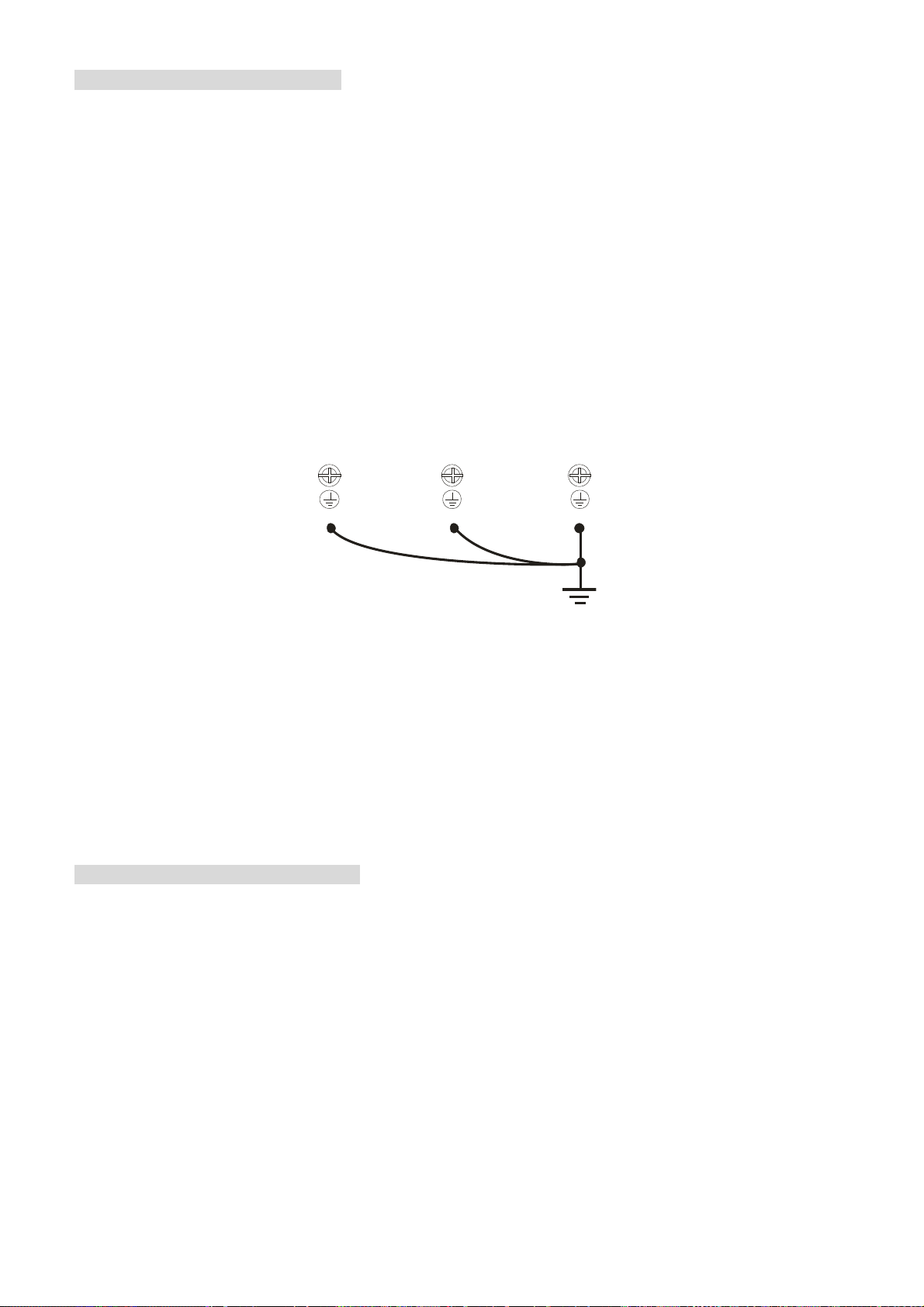
Important points regarding ground connection
To ensure the safety of personnel, proper operation, and to reduce electromagnetic radiation, the
drive must be properly grounded during installation.
The diameter of the cables must comply with the local safety regulations.
The shield of shielded cables must be connected to the ground of the drive to meet safety regulations.
The shield of shielded power cables can only be used as the ground for equipment when the
aforementioned points are met.
When installing more drives, do not connect the grounds of the drives in series but connect each drive
to ground.
Ground terminal
Wrong wiring setup for ground wires
Pay particular attention to the following points:
Do not remove the RFI jumper while the power is on.
Removing the RFI jumper will also disconnect the built-in EMC filter capacitors. Compliance with the
EMC specifications is no longer guaranteed.
The RFI jumper may not be removed if the mains power is a grounded power system.
The RFI jumper may not be removed while conducting high voltage tests. When conducting a high
voltage test to the entire facility, the mains power and the motor must be disconnected if the leakage
current is too high.
Floating Ground System (IT Systems)
A floating ground system is also called an IT system, an ungrounded system, or a high
impedance/resistance (greater than 30 Ω) grounded system.
Disconnect the RFI Jumper.
Check whether there is excess electromagnetic radiation affecting nearby low-voltage circuits.
In some situations, the transformer and cable naturally provide enough suppression. If in doubt, install
an extra electrostatic shielded cable on the power supply side between the main circuit and the control
terminals to increase security.
Do not install an external EMC filter. The EMC filter is connected to ground through the filter
capacitors, thus connecting power input to ground. This is very dangerous and can easily damage the
drive.
1-5
Page 11
1
1
1
1
1
Chapter 1 Introduction MS300
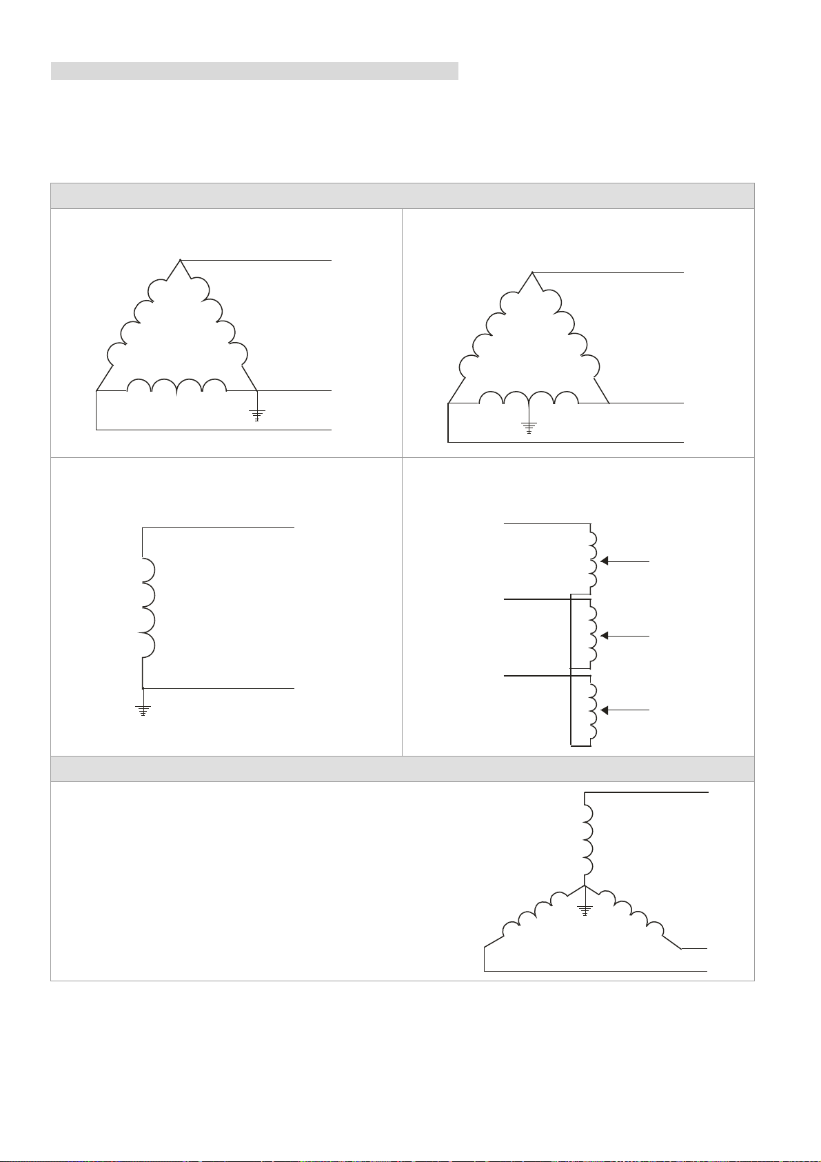
Asymmetric Ground System (Corner Grounded TN Systems)
Caution: Do not remove the RFI jumper while the input terminal of the drive carries power.
In the following four situations, the RFI jumper must be removed. This is to prevent the system from
grounding through the RFI and filter capacitors, damaging the drive.
RFI jumper must be removed
1. Grounding at a corner in a triangle configuration
L
L2
L3
3. Grounding at one end in a single-phase
configuration
L
2. Grounding at a midpoint in a polygonal
configuration
L
L2
L3
4. No stable neutral grounding in a three-phase
autotransformer configuration
L
L1
L2
N
RFI jumper can be used
Internal grounding through RFI capacitors, which reduce
electromagnetic radiation. In a symmetrically grounding
power system with higher EMC requirements, an EMC filter
can be installed. As a reference, the diagram on the right is
a symmetrical grounding power system.
L2
L3
L3
L
L2
L3
1-6
Page 12
Chapter 2 Dimensions MS300
Chapter 2 Dimension
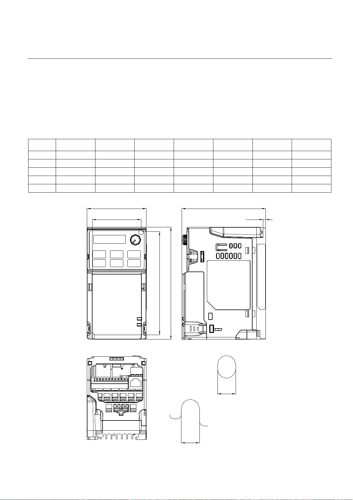
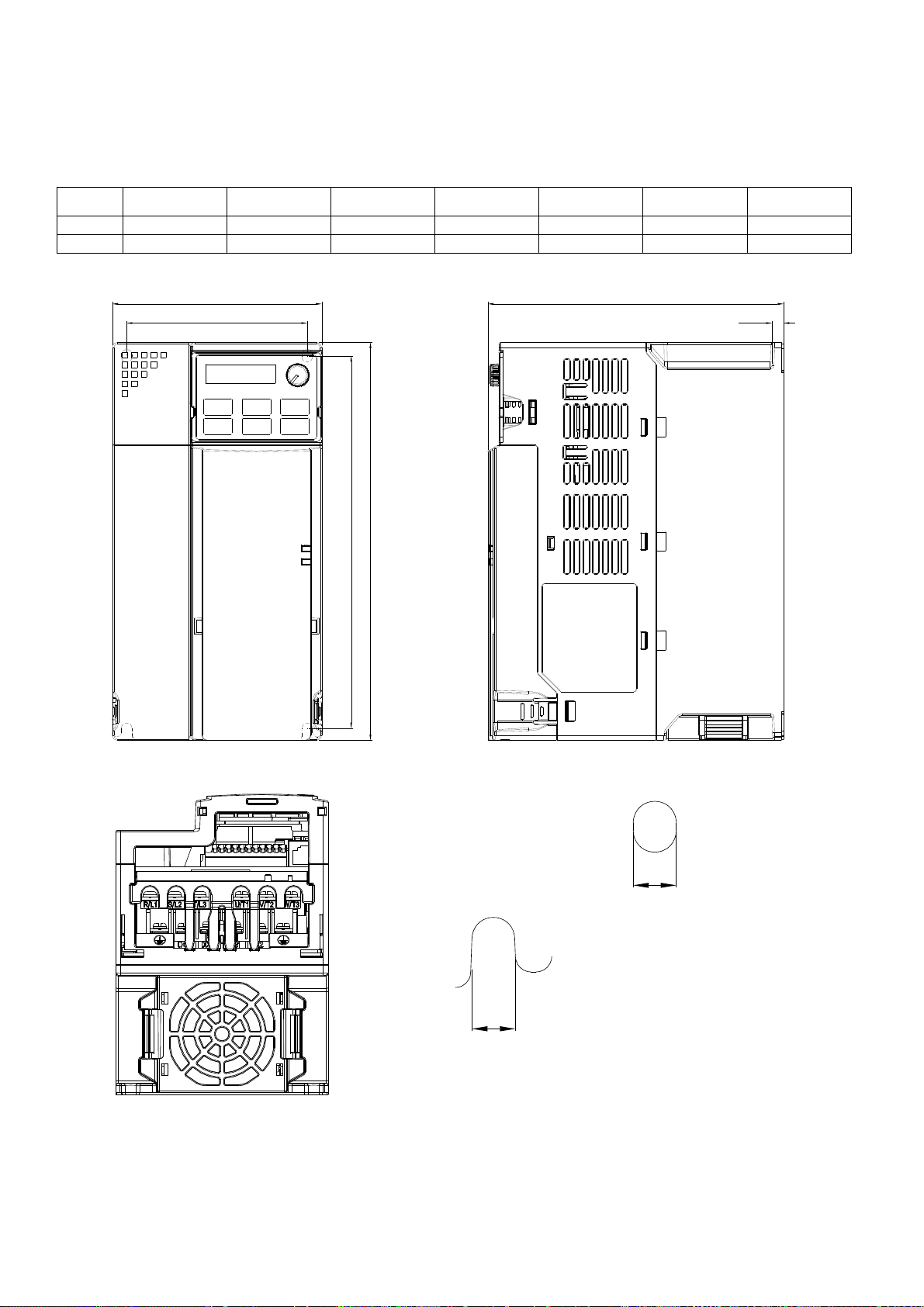
Frame A
A1: VFD1A6MS11ANSAA; VFD1A6MS11ENSAA; VFD1A6MS21ANSAA; VFD1A6MS21ENSAA;
VFD1A6MS23ANSAA; VFD1A6MS23ENSAA
A2: VFD2A8MS23ANSAA; VFD2A8MS23ENSAA
A3: VFD2A5MS11ANSAA; VFD2A5MS11ENSAA; VFD2A8MS21ANSAA; VFD2A8MS21ENSAA
A4: VFD1A5MS43ANSAA; VFD1A5MS43ENSAA
A5: VFD4A8MS23ANSAA; VFD4A8MS23ENSAA; VFD2A7MS43ANSAA; VFD2A7MS43ENSAA
Unit: mm [inch]
Frame W H D W1 H1 D1 S1
A1 68.0 [2.68] 128.0 [5.04] 96.0 [3.78] 56.0 [2.20] 118.0 [4.65] 3.0 [0.12] 5.2 [0.20]
A2 68.0 [2.68] 128.0 [5.04] 110.0 [4.33] 56.0 [2.20] 118.0 [4.65] 3.0 [0.12] 5.2 [0.20]
A3 68.0 [2.68] 128.0 [5.04] 125.0 [4.92] 56.0 [2.20] 118.0 [4.65] 3.0 [0.12] 5.2 [0.20]
A4 68.0 [2.68] 128.0 [5.04] 129.0 [5.08] 56.0 [2.20] 118.0 [4.65] 3.0 [0.12] 5.2 [0.20]
A5 68.0 [2.68] 128.0 [5.04] 143.0 [5.63] 56.0 [2.20] 118.0 [4.65] 3.0 [0.12] 5.2 [0.20]
W
D
W1
H1
D1
H
S1
Mounting Hole
S1
2-1
Mo u n ting H o l e
Page 13
Chapter 2 Dimensions MS300
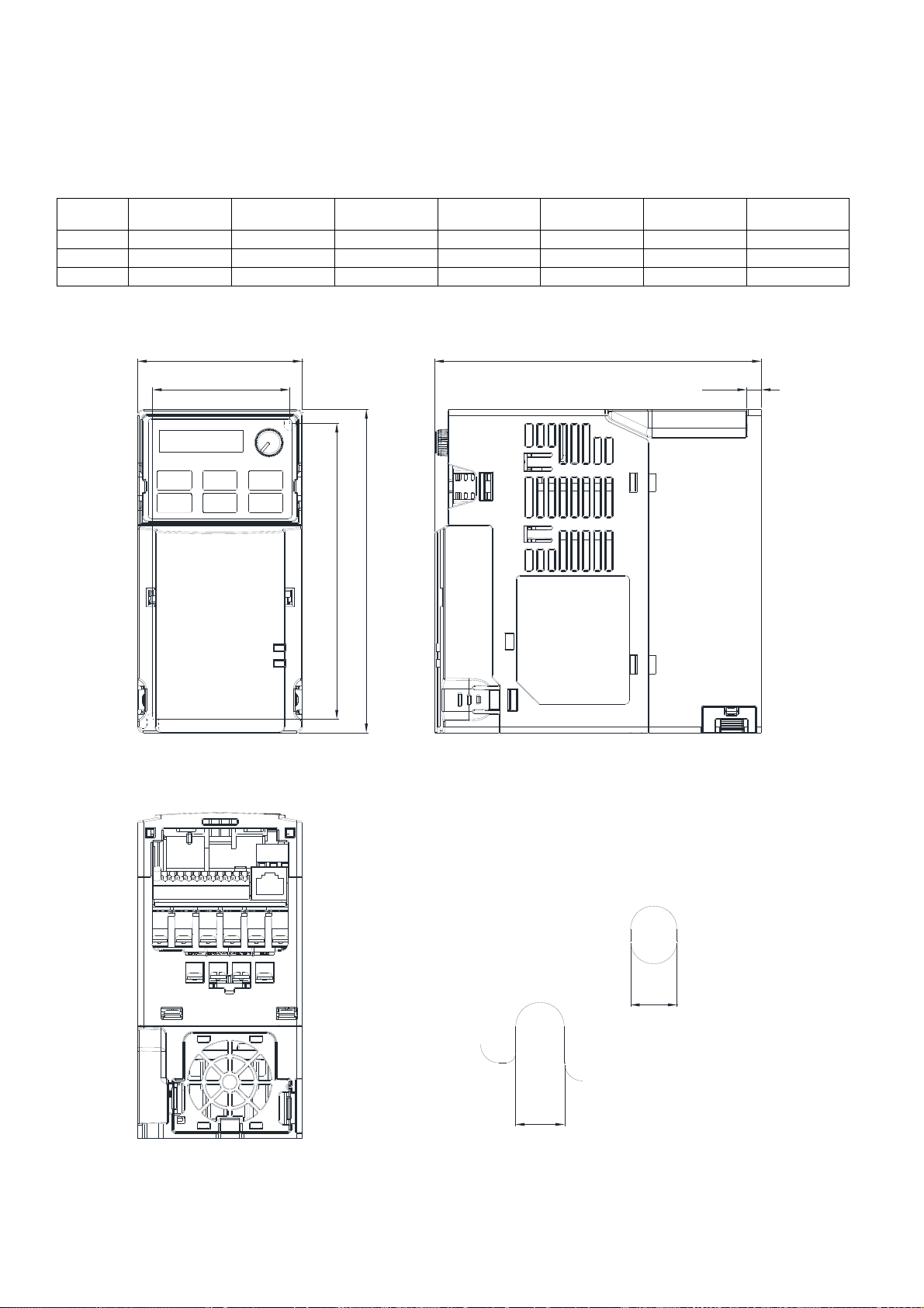
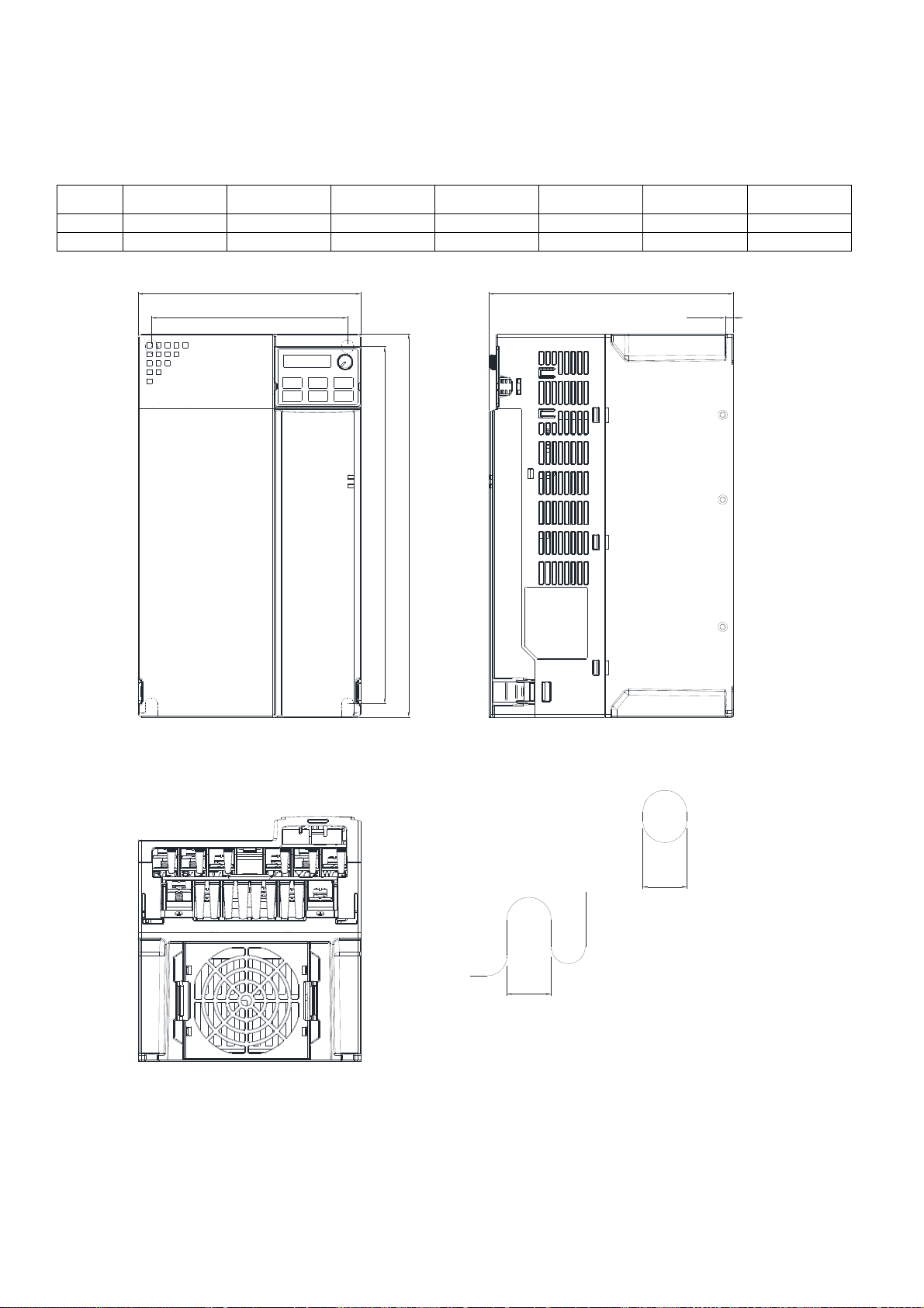
Frame B
B1: VFD7A5MS23ANSAA; VFD7A5MS23ENSAA; VFD4A2MS43ANSAA; VFD4A2MS43ENSAA
B2: VFD4A8MS21ANSAA; VFD4A8MS21ENSAA
B3: VFD1A6MS21AFSAA; VFD2A8MS21AFSAA; VFD4A8MS21AFSAA; VFD1A5MS43AFSAA;
VFD2A7MS43AFSAA; VFD4A2MS43AFSAA
Unit: mm [inch]
Frame W H D W1 H1 D1 S1
B1 72.0 [2.83] 142.0 [5.59] 143.0 [5.63] 60.0 [2.36] 130.0 [5.63] 6.4 [0.25] 5.2 [0.20]
B2 72.0 [2.83] 142.0 [5.59] 143.0 [5.63] 60.0 [2.36] 130.0 [5.63] 3.0 [0.12] 5.2 [0.20]
B3 72.0 [2.83] 142.0 [5.59] 159.0 [6.26] 60.0 [2.36] 130.0 [5.63] 4.3 [0.17] 5.2 [0.20]
W
W1
H1
D
D1
H
S1
Mounting Hole
S1
Detail A (Mounting Hole)
2-2
Page 14

Chapter 2 Dimensions MS300
Frame C
C1: VFD4A8MS11ANSAA; VFD4A8MS11ENSAA; VFD7A5MS21ANSAA; VFD7A5MS21ENSAA;
VFD11AMS21ANSAA; VFD11AMS21ENSAA; VFD11AMS23ANSAA; VFD11AMS23ENSAA;
VFD17AMS23ANSAA; VFD17AMS23ENSAA; VFD5A5MS43ANSAA; VFD5A5MS43ENSAA;
VFD9A0MS43ANSAA; VFD9A0MS43ENSAA
C2: VFD7A5MS21AFSAA; VFD11AMS21AFSAA; VFD5A5MS43AFSAA; VFD9A0MS43AFSAA
Unit: mm [inch]
Frame W H D W1 H1 D1 S1
C1 87.0 [3.43] 157.0 [6.18] 152.0 [5.98] 73.0 [2.87] 144.5 [5.69] 5.0 [0.20] 5.5 [0.22]
C2 87.0 [3.43] 157.0 [6.18] 179.0 [7.05] 73.0 [2.87] 144.5 [5.69] 5.0 [0.20] 5.5 [0.22]
W
W1
H1
D
D1
H
S1
Mounting Hole
S1
Mounting Hole
2-3
Page 15
Chapter 2 Dimensions MS300
Frame D
D1: VFD25AMS23ANSAA; VFD25AMS23ENSAA; VFD13AMS43ANSAA; VFD13AMS43ENSAA;
VFD17AMS43ANSAA; VFD17AMS43ENSAA
D2: VFD13AMS43AFSAA; VFD17AMS43AFSAA
Unit: mm [inch]
Frame W H D W1 H1 D1 S1
D1 109.0 [4.29] 207.0 [8.15] 154.0 [6.06] 94.0 [3.70] 193.8 [7.63] 6.0 [0.24] 5.5 [0.22]
D2 109.0 [4.29] 207.0 [8.15] 187.0 [7.36] 94.0 [3.70] 193.8 [7.63] 6.0 [0.24] 5.5 [0.22]
W
W1
H1
D
D1
H
S1
Mounting Hole
S1
Mounting Hole
2-4
Page 16

Chapter 2 Dimensions MS300
Frame E
E1: VFD33AMS23ANSAA; VFD33AMS23ENSAA; VFD49AMS23ANSAA; VFD49AMS23ENSAA;
VFD25AMS43ANSAA; VFD25AMS43ENSAA; VFD32AMS43ANSAA; VFD32AMS43ENSAA
E2: VFD25AMS43AFSAA; VFD32AMS43AFSAA
Unit: mm [inch]
Frame W H D W1 H1 D1 S1
E1 130.0 [5.12] 250.0 [9.84] 185.0 [7.83] 115.0 [4.53] 236.8 [9.32] 6.0 [0.24] 5.5 [0.22]
E2 130.0 [5.12] 250.0 [9.84] 219.0 [8.62] 115.0 [4.53] 236.8 [9.32] 6.0 [0.24] 5.5 [0.22]
W
W1
H1
D
D1
H
S1
Mounting Hole
S1
Mounting H ole
2-5
Page 17
Chapter 2 Dimensions MS300
Frame F
F1: VFD65AMS23ANSAA; VFD65AMS23ENSAA; VFD38AMS43ANSAA; VFD38AMS43ENSAA;
VFD45AMS43ANSAA; VFD45AMS43ENSAA
F2: VFD38AMS43AFSAA; VFD45AMS43AFSAA
Unit: mm [inch]
Frame W H D W1 H1 D1 S1
F1 175.0 [6.89] 300.0 [11.81] 192.0 [7.56] 154.0 [6.06] 279.5 [11.00] 6.5 [0.26] 8.4 [0.33]
F2 175.0 [6.89] 300.0 [11.81] 244.0 [9.61] 154.0 [6.06] 279.5 [11.00] 6.5 [0.26] 8.4 [0.33]
W
W1
H1
D
D1
H
S1
Mounting Hole
S1
2-6
Mounting Hole
Page 18
Chapter 2 Dimensions MS300
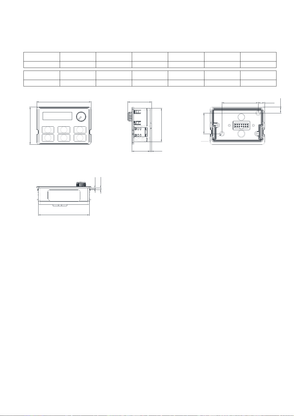
Digital Keypad
KPMS-LE01
Unit: mm [inch]
W W1 W2 W3 H H1 H2
68.0 [2.67] 63.8 [2.51] 45.2 [1.78] 8.0 [0.31] 46.8 [1.84] 42.0 [1.65] 26.0 [1.02]
H3 D D1 D2 D3 D4 S1
7.5 [0.31] 30.0 [1.18] 22.7 [0.89] 2.0 [0.08] 2.2 [0.09] 1.3 [0.05] M3*0.5(2X)
W
H
D3
D4
W1
D
D1 D2
H1
S1
H2
W2
W3
H3
2-7
Page 19

Chapter 2 Dimensions MS300
[ This page intentionally left blank ]
2-8
Page 20

Chapter 3 Installation MS300
Chapter 3 Installation
Minimum Mounting Clearance and Installation
Prevent fiber particles, scraps of paper, shredded wood saw dust, metal particles, etc. from adhering
to the heat sink
Install the AC motor drive in a metal cabinet. When installing one drive below another one, use a
metal separation between the AC motor drives to prevent mutual heating and to prevent the risk of
accidental fire.
Install the AC motor drive in Pollution Degree 2 environments only: normally only nonconductive
pollution occurs and temporary conductivity caused by condensation is expected.
The appearances shown in the following figures are for reference only.
Airflow direction:
Single drive installation
inflow outflow distance
Side-by-side horizontal installation
Minimum mounting clearance
o
Installation method A (mm) B (mm) C (mm)
Max. (Without derating) Max. (Derating)
Ambient temperature (
Single drive installation 50 30 - 50 60
Side-by-side horizontal installation 50 30 30 50 60
Zero stack installation 50 30 0 40 50
NOTE
The minimum mounting clearances A~C stated in the table above applies to AC motor drives installation. Failing to
follow the minimum mounting clearances may cause the fan to malfunction and heat dissipation problems.
C)
3-1
Page 21
Chapter 3 Installation MS300
Air flow rate for cooling Power Dissipation
Frame
A
Model No.
VFD1A6MS11ANSAA
VFD1A6MS11ENSAA
VFD2A5MS11ANSAA
VFD2A5MS11ENSAA
VFD1A6MS21ANSAA
VFD1A6MS21ENSAA
VFD2A8MS21ANSAA
VFD2A8MS21ENSAA
VFD1A6MS23ANSAA
VFD1A6MS23ENSAA
VFD2A8MS23ANSAA
VFD2A8MS23ENSAA
VFD4A8MS23ANSAA
VFD4A8MS23ENSAA
VFD1A5MS43ANSAA
VFD1A5MS43ENSAA
VFD2A7MS43ANSAA
VFD2A7MS43ENSAA
Flow Rate
(Unit: cfm)
Flow Rate
(Unit: m3 / hr)
0.0 0.0
Loss External
(Heat sink, unit: W)
8.0 10.0 18.0
14.2 13.1 27.3
8.0 10.3 18.3
16.3 14.5 30.8
8.6 10.0 18.6
16.5 12.6 29.1
31.0 13.2 44.2
17.6 11.1 28.7
30.5 17.8 48.3
Internal
(Unit: W)
Total
(Unit: W)
B
C
VFD1A6MS21AFSAA 0.0 0.0 8.0 10.3 18.3
VFD2A8MS21AFSAA 10.0 16.99 16.3 14.5 30.8
VFD4A8MS21ANSAA
VFD4A8MS21ENSAA
VFD4A8MS21AFSAA
VFD7A5MS23ANSAA
VFD7A5MS23ENSAA
VFD1A5MS43AFSAA 17.6 11.1 28.7
0.0 0.0 29.1 20.1 49.2
29.1 20.1 49.2
50.1 24.2 74.3
10.0 16.99
VFD2A7MS43AFSAA 30.5 17.8 48.3
VFD4A2MS43ANSAA
VFD4A2MS43ENSAA
45.9 21.7 67.6
VFD4A2MS43AFSAA
VFD4A8MS11ANSAA
VFD4A8MS11ENSAA
29.1 23.9 53.0
VFD7A5MS21ANSAA
VFD7A5MS21ENSAA
46.5 31.0 77.5
VFD7A5MS21AFSAA
VFD11AMS21ANSAA
VFD11AMS21ENSAA
70.0 35 105
VFD11AMS21AFSAA
VFD11AMS23ANSAA
VFD11AMS23ENSAA
VFD17AMS23ANSAA
VFD17AMS23ENSAA
16.0 27.2
76.0 30.7 106.7
108.2 40.1 148.3
VFD5A5MS43ANSAA
VFD5A5MS43ENSAA
60.6 22.8 83.4
VFD5A5MS43AFSAA
VFD9A0MS43ANSAA 93.1 42 135.1
3-2
Page 22

Chapter 3 Installation MS300
Air flow rate for cooling Power Dissipation
Frame
D
E
F
Model No.
VFD9A0MS43ENSAA
VFD9A0MS43AFSAA
VFD25AMS23ANSAA
VFD25AMS23ENSAA
VFD13AMS43ANSAA
VFD13AMS43ENSAA
VFD13AMS43AFSAA
VFD17AMS43ANSAA
VFD17AMS43ENSAA
VFD17AMS43AFSAA
VFD33AMS23ANSAA
VFD33AMS23ENSAA
VFD49AMS23ANSAA
VFD49AMS23ENSAA
VFD25AMS43ANSAA
VFD25AMS43ENSAA
VFD25AMS43AFSAA
VFD32AMS43ANSAA
VFD32AMS43ENSAA
VFD32AMS43AFSAA
VFD65AMS23ANSAA
VFD65AMS23ENSAA
VFD38AMS43ANSAA
VFD38AMS43ENSAA
VFD38AMS43AFSAA
VFD45AMS43ANSAA
VFD45AMS43ENSAA
VFD45AMS43AFSAA
Flow Rate
(Unit: cfm)
23.4 39.7
53.7 91.2
67.9 115.2
Flow Rate
(Unit: m3 / hr)
Loss External
(Heat sink, unit: W)
192.8 53.3 246.1
132.8 39.5 172.3
164.7 55.8 220.5
244.5 79.6 324.1
374.2 86.2 460.4
234.5 69.8 304.3
319.8 74.3 394.1
492.0 198.2 690.2
423.5 181.6 605.1
501.1 200.3 701.4
Internal
(Unit: W)
Total
(Unit: W)
3-3
Page 23

Chapter 3 Installation MS300
[ This page intentionally left blank ]
3-4
Page 24

Chapter 4 WiringMS300
Chapter 4 Wiring
4-1 Wiring
4-2 System Wiring Diagram
4-1
Page 25
Chapter 4 WiringMS300
After removing the front cover, please check if the power and control terminals are clearly visible.
Please read following precautions to avoid wiring mistakes.
It is crucial to cut off the AC motor drive power before doing any wiring. A charge
may still remain in the DC bus capacitors with hazardous voltages even after the
DANGER
power has been turned off a short time. Therefore it is suggested to measure the
remaining voltage with a DC voltmeter on +1/DC+ and DC- before doing any
wiring. For your personnel saftery, please do not start wiring before the voltage
drops to a safe level < 25 Vdc. Wiring the installation with a remaning voltage
condition may cause injuries, sparks and short circuits.
Only qualified personnel familiar with AC motor drives is allowed to perform
installation, wiring and commissioning. Make sure the power is turned off before
wiring to prevent electric shocks.
The terminals R/L1、S/L2、T/L3 are for mains power input. If mains power is
wrongly connected to other terminals, it may result in damage to the equipment.
The voltage and current should lie within the range as indicated on the nameplate
(see Chapter 1-1).
All units must be grounded directly to a common ground terminal to prevent
electrical shocks or damage by lightning.
Please make sure to tighten the screw of the main circuit terminals to prevent
sparks due to the loosening of vibrations.
When wiring, please choose the wires with specification that complies with local
regulations for your personal safety.
Check following items after finishing the wiring:
1. Are all connections correct?
2. Any loose wires?
3. Any short-circuits between the terminals or to ground?
4-2
Page 26
4-1 Wiring
Chapter 4 WiringMS300
4-3
Page 27
Chapter 4 WiringMS300
Figure 1
4-4
Page 28
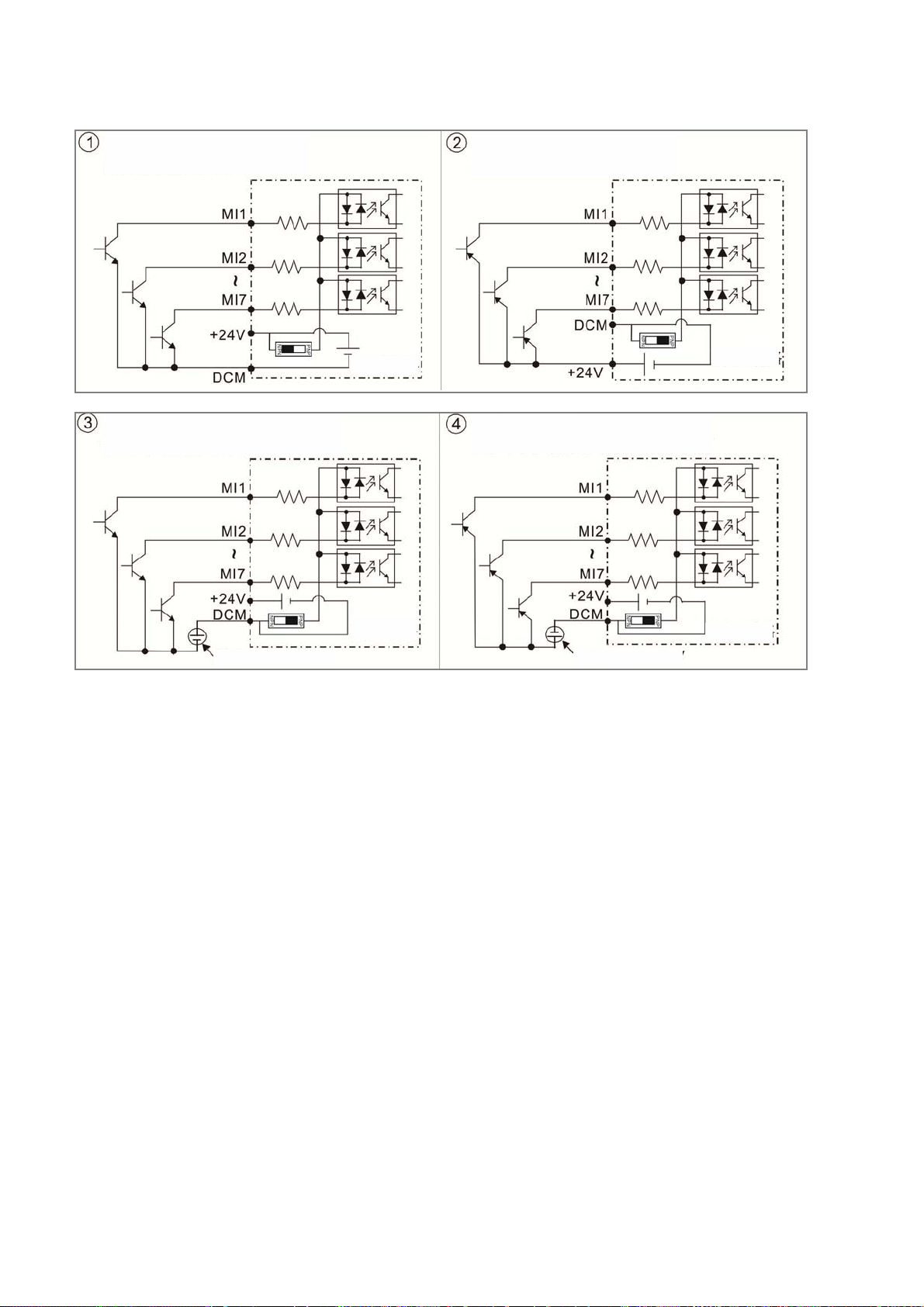
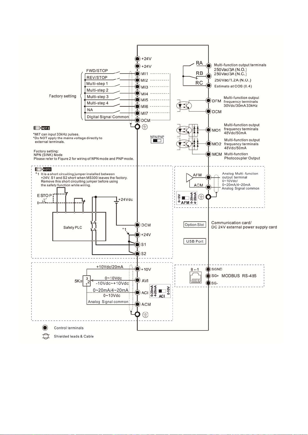
Figure 2
SINK (NPN) / SOURCE (PNP) Mode
Chapter 4 WiringMS300
Sink Mode
with internal power (+24Vdc)
Sink Mode
with external power
internal
circuit
Source Mode
with internal power (+24Vdc)
Source Mode
with external power
internal
circuit
internal
circuit
external power +24V external power +24V
internal
circuit
4-5
Page 29
Chapter 4 WiringMS300
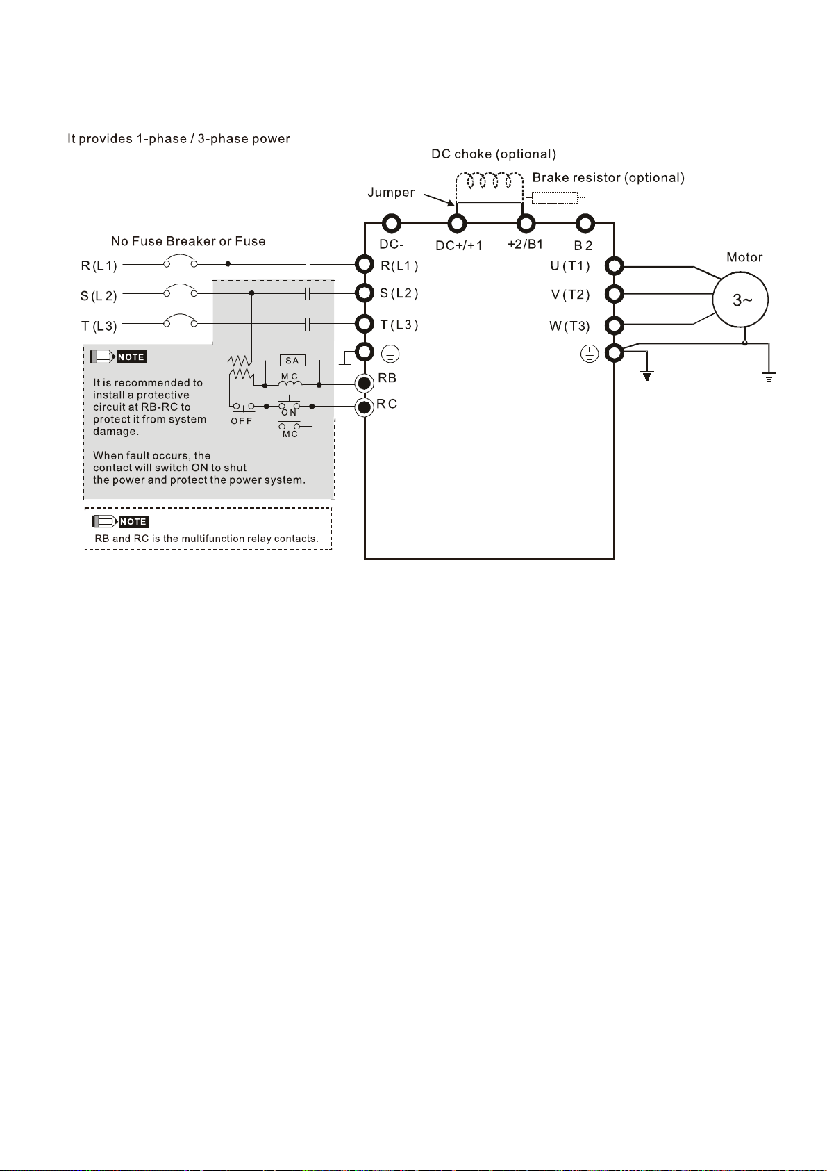
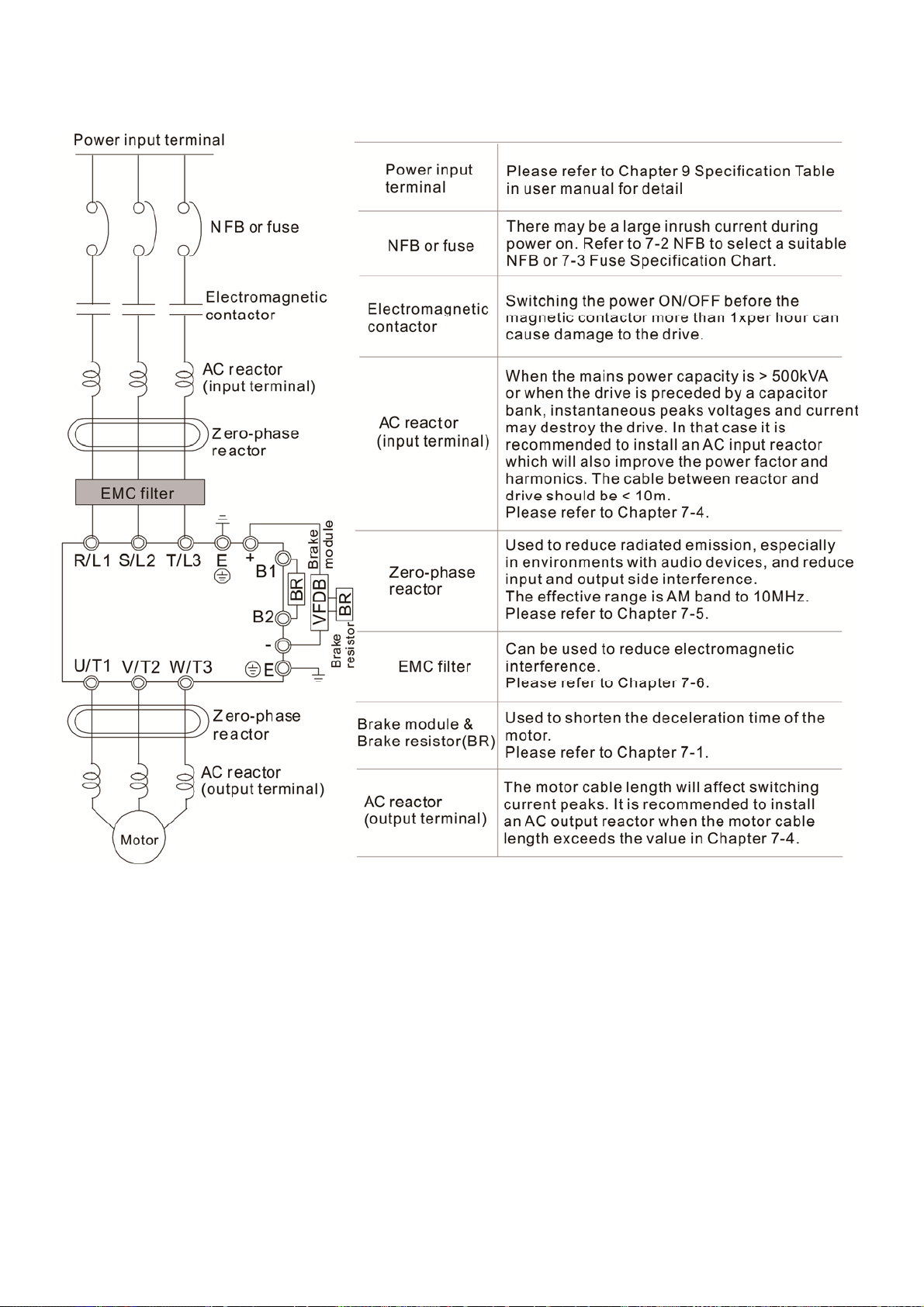
4-2 System Wiring Diagram
4-6
Page 30

Chapter 5 Main Circuit TerminalsMS300
Chapter 5 Main Circuit Terminals
5-1 Main Circuit Diagram
5-2 Main Circuit Terminals
5-1
Page 31

Chapter 5 Main Circuit TerminalsMS300
Fasten the main circuit terminal screws to prevent sparking by loose screws
due to vibration.
When needed, only use an inductive filter at the motor output terminals
DANGER
U/T1, V/T2, W/T3 of the AC motor drive. DO NOT use phase-compensation
capacitors or L-C (Inductance-Capacitance) or R-C
(Resistance-Capacitance), unless approved by Delta.
DO NOT connect brake resistor directly to +1/DC+ to DC-, +2/B1 to DC- to
prevent damage to the drive.
Ensure proper insulation of main circuit wiring in accordance with the
relevant safety regulations.
Main power terminals
R/L1, S/L2 and T/L3 have no phase-sequence requirement; they can be
connected in any sequence.
It is recommended adding a magnetic contactor (MC) at the power input to
cut off power quickly and reduce malfunctioning when the protection
function of the AC motor drive is activated. Both ends of the MC should have
an R-C surge absorber.
Please ensure voltages and currents are within specification.
When using a general GFCI (Ground Fault Circuit Interrupter), select a
sensitivity ≥200mA and ≥0.1s operation time to avoid nuisance tripping.
Please use conduits or shielded cables for the power wiring and ground
both ends of the conduit or shielded cables.
DO NOT run/stop the drive by turning the power ON/OFF. Run/stop the
drive by RUN/STOP command. If you still need to run/stop the drive by
turning power ON/OFF, it is strongly recommended to do so only ONCE per
hour.
To comply with UL standards, connect the drive to a 3WYE type of mains
power system.
Output terminals for main circuit
Use a well-insulated motor, suitable for inverter operation.
When the AC drive output terminals U/T1, V/T2, and W/T3 are connected to
the motor terminals U/T1, V/T2, and W/T3 respectively, the motor will rotate
counterclockwise (as viewed on the shaft end of the motor) when a forward
operation command is received. To permanently reverse the direction of
rotation, switch over any two motor leads.
Fo wa rd
Running
5-2
Page 32

1+2
/B1
2
/B1
2
Chapter 5 Main Circuit TerminalsMS300
Terminals for connecting DC reactor, external brake resistor and DC
circuit
These are the terminals for connecting the DC-reactor to improve the power
factor and harmonics. At delivery they are shorted by a jumper. Please
remove it before connecting the DC reactor.
The jumper must be fastened tight when it does not connect DC reactor, use
DC+/+1, +2/B1 to execute common DC bus, or connect with brake resistor,
otherwise the drive might lose power or the terminals will be broken.
DC reactor optional ( )
DC+/+
Connect a brake resistor in applications with frequent deceleration, short
deceleration time, too low braking torque or requiring increased braking
torque.
Brake res istor
(optional)
+
The external brake resistor should connect to the terminals [+2 / B1], [B2] of
AC motor drives.
DO NOT short circuit or connect a brake resistor directly to DC+/+1 and
DC-, +2/B1 to DC- otherwise the drive will be damaged.
DC+ and DC- are to be connected in common DC bus applications, please
refer to Chapter 5-1(Main Circuit Terminal) for the wiring terminal
specification and the wire gauge information.
B
Remove the front cover
The front cover shall be removed before connecting the main circuit terminals and control circuit
terminals. Removing the cover acc. to the figure below.
The figure below shows Frame A model for example. Removing the cover on other frame sizes is
similar.
Press the clip on both sides, and take out by rotating.
5-3
Page 33

Chapter 5 Main Circuit TerminalsMS300
5-1 Main Circuit Diagram
Terminals Descriptions
R/L1, S/L2 Mains input terminals 1-phase
R/L1, S/L2, T/L3 Mains input terminals 3-phase
U/T1, V/T2, W/T3 Motor output terminals for connecting 3-phase
Connections for DC reactor to improve the power factor and harmonics.
+1, +2
The jumper needs to be removed in that case.
Connections for brake unit (VFDB series)
DC+, DC-
Common DC Bus
B1, B2 Connections for brake resistor (optional)
Earth connection, please comply with local regulations.
IM and PM motors.
5-4
Page 34

Chapter 5 Main Circuit TerminalsMS300
5-2 Main Circuit Terminals
It needs following additional terminal when wiring. The additional terminal dimension should comply
with the following figure 1.
After crimping the wire to the ring lug (must UL approved), UL and CSA approved R/C (YDPU2)
heat shrink tubing rated min 600Vac insulation shall be install over the live part. Please refer to the
following figure 2.
Dimensions of Ring Lug
Frame AWG
18
A
B
C
D
E
F
16
14
14
12
14
12
10
8
12
10
8
8
6
4
6
4
2
Kit P/N
RNBS
1-3.7
RNBS
2-3.7
RNBS
2-3.7
RNBS2-4
RNBS5-4
RNBS2-4
RNBS5-4
RNBS5-4
RNBS8-4
RNBS5-4
RNBS5-4
RNBS8-4
RNBS8-5
RNB14-5
RNBS22-5
RNBS14-6
RNBS22-6
RNBS38-6
A
(MAX) B (MAX)C (MIN)D (MAX)
9.8 3.2 4.8 4.1 3.7 13.0 4.2 6.6 0.8
12.1 3.6 6.1 5.6 4.3 13.0 4.5 7.2 1
17.8 5.0 6.1 7.2 4.3 13.0 5.5 8.0 1.2
17.8 5.0 6.1 7.2 4.3 13.0 5.5 8.0 1.2
27.1 6.1 10.5 11.5 5.3 13.0 6.5 12.2 1.7
35.0 9.0 13.3 14.0 6.2 13.0 19.5 18.0 1.8
d2
(MIN)E (MIN) F (MIN) W (MAX)t (MAX)
Unit: mm
5-5
Page 35

Chapter 5 Main Circuit TerminalsMS300
Frame A
Main circuit terminals:
R/L1, S/L2, T/L3, U/T1, V/T2, W/T3,
,DC-, DC+/+1, +2/B1, B2,
Note: 1-phase model with no T/L3 terminal
Max.
Models
Wire
Gauge
VFD1A6MS11ANSAA
VFD1A6MS11ENSAA
VFD2A5MS11ANSAA
VFD2A5MS11ENSAA
VFD1A6MS21A SAA
VFD1A6MS21ENSAA
VFD2A8MS21ANSAA
VFD2A8MS21ENSAA
VFD1A6MS23ANSAA
VFD1A6MS23ENSAA
VFD2A8MS23ANSAA
VFD2A8MS23ENSAA
VFD4A8MS23ANSAA
VFD4A8MS23ENSAA
VFD1A5MS43ANSAA
VFD1A5MS43ENSAA
VFD2A7MS43ANSAA
VFD2A7MS43ENSAA
14 AWG
[2.1 mm
If you install at Ta 45°C above environment, please select copper
wire which have voltage rating 600V and temperature resistant 90°C
or above.
If you install at Ta 45°C environment, please select copper wire
which have voltage rating 600V and temperature resistant 75°C or
90°C.
For UL installation compliant, you have to use copper wires when
installation, the wire gauge is based on temperature resistant 75°C
which is according to the requirements and recommendations from
UL. Do not reduce the wire gauge when using higher temperature
wire.
Min. Wire
2
]
[0.82mm
[0.82mm
Gauge
16AWG
[1.3mm
14AWG
[2.1mm
16AWG
[1.3mm
14AWG
[2.1mm
18AWG
16AWG
[1.3mm
18AWG
Screw
2
]
2
]
2
]
2
]
M 3.5
2
]
2
]
2
]
Torque
(±10%)
9 kg-cm
[7.8 lb-in.]
[0.88 Nm]
5-6
Page 36

Chapter 5 Main Circuit TerminalsMS300
Frame B
Main circuit terminals:
R/L1, S/L2, T/L3, U/T1, V/T2, W/T3,
,DC-, DC+/+1, +2/B1, B2,
Note: 1-phase model with no T/L3 terminal
Models
VFD1A6MS21AFSAA
VFD2A8MS21AFSAA
VFD4A8MS21ANSAA
VFD4A8MS21ENSAA
VFD4A8MS21AFSAA
VFD7A5MS23ANSAA
VFD7A5MS23ENSAA
VFD1A5MS43AFSAA
VFD2A7MS43AFSAA
VFD4A2MS43ANSAA
VFD4A2MS43ENSAA
VFD4A2MS43AFSAA
Max. Wire
Gauge
12 AWG
[3.3 mm
If you install at Ta 45°C above environment, please select copper
wire which have voltage rating 600V and temperature resistant 90°C
or above.
If you install at Ta 45°C environment, please select copper wire
which have voltage rating 600V and temperature resistant 75°C or
90°C.
For UL installation compliant, you have to use copper wires when
installation, the wire gauge is based on temperature resistant 75°C
which is according to the requirements and recommendations from
UL. Do not reduce the wire gauge when using higher temperature
wire.
Min. Wire
2
]
[2.1 mm2]
Gauge
14 AWG
Screw
M4
Torque
(±10%)
15 kg-cm
[13.0 lb-in]
[1.47 Nm]
5-7
Page 37

Chapter 5 Main Circuit TerminalsMS300
Frame C
Main circuit terminals:
R/L1, S/L2, T/L3, U/T1, V/T2, W/T3,
,DC-, DC+/+1, +2/B1, B2,
Note: 1-phase model with no T/L3 terminal
Models
VFD4A8MS11ANSAA
VFD4A8MS11ENSAA
VFD7A5MS21ANSAA
VFD7A5MS21ENSAA
VFD7A5MS21AFSAA
VFD11AMS21ANSAA
VFD11AMS21ENSAA
VFD11AMS21AFSAA
VFD11AMS23ANSAA
VFD11AMS23ENSAA
VFD17AMS23ANSAA
VFD17AMS23ENSAA
VFD5A5MS43ANSAA
VFD5A5MS43ENSAA
VFD5A5MS43AFSAA
VFD9A0MS43ANSAA
VFD9A0MS43ENSAA
VFD9A0MS43AFSAA
Max. Wire
Gauge
8 AWG
[8.4 mm
If you install at Ta 45°C above environment, please select copper
wire which have voltage rating 600V and temperature resistant 90°C
or above.
If you install at Ta 45°C environment, please select copper wire
which have voltage rating 600V and temperature resistant 75°C or
90°C.
For UL installation compliant, you have to use copper wires when
installation, the wire gauge is based on temperature resistant 75°C
which is according to the requirements and recommendations from
UL. Do not reduce the wire gauge when using higher temperature
wire.
2
]
Min. Wire
Gauge
10 AWG
[5.3mm
[8.4mm
12 AWG
[3.3 mm
10 AWG
[5.3 mm
14 AWG
[2.1 mm
8 AWG
2
]
2
]
2
]
2
]
2
]
Screw
M4
Torque
(±10%)
20 kg-cm
[17.4 lb-in.]
[1.96 Nm]
5-8
Page 38

Chapter 5 Main Circuit TerminalsMS300
Frame D
Main circuit terminals:
R/L1, S/L2, T/L3, U/T1, V/T2, W/T3,
, DC-, DC+/+1, +2/B1, B2,
Models
VFD25AMS23ANSAA
VFD25AMS23ENSAA
VFD13AMS43ANSAA
VFD13AMS43ENSAA
VFD13AMS43AFSAA
VFD17AMS43ANSAA
VFD17AMS43ENSAA
VFD17AMS43AFSAA
Max. Wire
Gauge
8 AWG
[8.4mm
If you install at Ta 45°C above environment, please select copper
wire which have voltage rating 600V and temperature resistant 90°C
or above.
If you install at Ta 45°C environment, please select copper wire
which have voltage rating 600V and temperature resistant 75°C or
90°C.
For UL installation compliant, you have to use copper wires when
installation, the wire gauge is based on temperature resistant 75°C
which is according to the requirements and recommendations from
UL. Do not reduce the wire gauge when using higher temperature
wire.
2
]
Min. Wire
Gauge
8 AWG
2
[8.4mm
10 AWG
[5.3mm
]
2
]
Screw
M4
Torque
(±10%)
20kg-cm
[17.4 lb-in.]
[1.96Nm]
5-9
Page 39

Chapter 5 Main Circuit TerminalsMS300
Frame E
Main circuit terminals:
R/L1, S/L2, T/L3, U/T1, V/T2, W/T3,
, DC-, DC+/+1, +2/B1, B2,
Models
VFD33AMS23ANSAA
VFD33AMS23ENSAA
VFD49AMS23ANSAA**
VFD49AMS23ENSAA**
VFD25AMS43ANSAA
VFD25AMS43ENSAA
VFD25AMS43AFSAA
VFD32AMS43ANSAA
VFD32AMS43ENSAA
VFD32AMS43AFSAA
Max. Wire
Gauge
6 AWG
[13.3 mm
4 AWG
[21.2 mm
6 AWG
[13.3 mm
If you install at Ta 45°C above environment, please select copper wire
which have voltage rating 600V and temperature resistant 90°C or
above.
If you install at Ta 45°C environment, please select copper wire which
have voltage rating 600V and temperature resistant 75°C or 90°C.
For UL installation compliant, you have to use copper wires when
installation, the wire gauge is based on temperature resistant 75°C
which is according to the requirements and recommendations from UL.
Do not reduce the wire gauge when using higher temperature wire.
** These drives must be wired with ring terminal that dimensions are
specified.
Min. Wire
2
]
[13.3 mm2]
2
]
[21.2 mm2]
2
]
[8.4 mm2]
Gauge
6 AWG
4 AWG
8 AWG
Screw
M5
Torque
(±10%)
25 kg-cm
[21.7 lb-in.]
[2.45 Nm]
5-10
Page 40

Chapter 5 Main Circuit TerminalsMS300
Frame F
Main circuit terminals:
R/L1, S/L2, T/L3, U/T1, V/T2, W/T3,
, DC-, DC+/+1, +2/B1, B2,
Models
VFD65AMS23ANSAA
VFD65AMS23ENSAA
VFD38AMS43ANSAA
VFD38AMS43ENSAA
VFD38AMS43AFSAA
VFD45AMS43ANSAA
VFD45AMS43ENSAA
VFD45AMS43AFSAA
Max. Wire
Gauge
2 AWG
[33.6 mm
If you install at Ta 45°C above environment, please select copper
wire which have voltage rating 600V and temperature resistant 90°
C or above.
If you install at Ta 45°C environment, please select copper wire
which have voltage rating 600V and temperature resistant 75°C or
90°C.
For UL installation compliant, you have to use copper wires when
installation, the wire gauge is based on temperature resistant 75°C
which is according to the requirements and recommendations from
UL. Do not reduce the wire gauge when using higher temperature
wire.
Min. Wire
Gauge
2 AWG
[33.6 mm
6 AWG
[13.3 mm
2
]
4 AWG
[21.2 mm
2
]
2
]
2
]
Screw
M6
Torque
(±10%)
40 kg-cm
[34.7 lb-in.]
[3.92 Nm]
5-11
Page 41

Chapter 5 Main Circuit TerminalsMS300
[ This page intentionally left blank ]
5-12
Page 42

Chapter 6 Control TerminalsMS300
Chapter 6 Control Terminals
Analog input terminals (AVI, ACI, ACM)
Analog input signals are easily affected by external noise. Use shielded wiring and
keep it as short as possible (<20 m) with proper grounding. If the noise is
inductive, connecting the shield to terminal ACM can bring improvement.
Use twisted-pair for weak analog signals.
If the analog input signals are affected by noise from the drive, please connect a
capacitor and ferrite core as indicated in the following diagram.
Wind each wire 3
times or more
around the core
Ferrite core
Contact input terminals(MI1~MI7, DCM, +24V)
Sink Mode
with internal power (+24Vdc)
Source Mode
with internal power (+24V dc)
internal
circuit
internal
circuit
Sink Mode
with external power
internal
circuit
exter nal power + 24V exter nal power + 24V
Source Mode
with external power
internal
circuit
When the photo-coupler is using internal power supply, the switch connection for Sink
and Source as below: MI-DCM: Sink mode, MI-+24 V: Source mode
Transistor Output Terminal (MO1, MO2, MCM)
Make sure to connect the digital outputs to the right polarity, see wiring diagram
When connecting a relay to the digital output, connect a surge absorber across the
coil and check the polarity.
6-1
Page 43

(
Chapter 6 Control TerminalsMS300
Specifications of Control Terminal
Specifications of RELAY Terminal
Wire Gauge: 20~18AWG [0.519~0.82 mm2]
Wire Gauge: 24~16 AWG [0.205~1.3 mm2];
Torque: 5 kg-cm / [4.3 Ib-in.] / [0.49 Nm]
4-20mA
0-20mA
ACI
S1
+24V
Safety function
+10V
MI1
MI2
MI3
0-10V
ACM
MI4
S2
0-10V
AFM
AVI
DCM
MI5
SG+
ACI
MI6
4-20mA
0-20mA
SG-
AFM
MI7
NPN
SGND
MO1
+24V
MCM
MO2
+24V
DCM
USB
DATAMATRIX
24P
32637012
SLOT 1
RELAY
DFM
DCM
RB
RA
RS485
Port
RC
PNP
Location Map of Control Terminal
Distribution Diagram of Control Terminal
Wiring precautions:
Delivery condition is +24V/ S1/ S2 shorted by jumper (as shown in figure above), please refer
to Chapter 4 Wiring for more details.
RELAY terminal is using PCB terminal block:
1. Tighten the wiring with slotted screwdriver, which is 3.5mm (wide) x 0.6mm (thick)
2. The ideal length of stripped wire at the connection side is 6~7mm.
3. When wiring bare wires, make sure they are perfectly arranged to go through the wiring
holes.
Control terminal is using spring clamp terminal block:
1. Tighten the wiring with slotted screwdriver, which is 2.5mm (wide) x 0.4mm (thick)
2. The ideal length of stripped wire at the connection side is 9mm.
3. When wiring bare wires, make sure they are perfectly arranged to go through the wiring
holes.
Wiring Specifications of Control Terminal
Conductor cross section solid
Conductor cross section stranded
Stranded with ferrules with plastic sleeve
Min. Wire Gauge Max. Wire Gauge
[0.519 mm
A B
14 8 3.5 1.4
Wire Gauge (AWG)
20 AWG
2
]
MAX)
D
18 AWG
[0.82 mm
20 AWG
[0.519 mm
W
2
]
2
]
Unit: mm
Ferrule: Type: AI 0,5 - 8 WH ,
Manufacturer: PHOENIX CONTACT
6-2
Page 44

r
Chapter 6 Control TerminalsMS300
Terminals Terminal Function Factory Setting (NPN mode)
+24V
MI1
~
MI7
DFM
DCM
MO1
Digital control signal common
(Source)
Multi-function input 1~7
Digital frequency meter
DFM
DCM
Digital frequency signal
common (Sink)
Multi-function Output 1
(photocoupler)
+24V ± 10 % 100 mA
Refer to parameters 02-01~02-07 to program the
multi-function inputs MI1~MI7.
Source Mode
ON: the activation current is 3.3 mA≧11Vdc
OFF: cut-off voltage≦5Vdc
Sink Mode
ON: the activation current is 3.3 mA ≦13Vdc
OFF: cut-off voltage≧19Vdc
When Pr. 02-00=0, MI1 and MI2 can be programmed
When Pr. 02-00≠0, the function of MI1 and MI2 is acc.
to Pr02-00 setting.
When Pr02-07=0, MI7 is pulse input with max.
frequency 33kHz (See Pr. 10-00, Pr. 10-02, Pr. 10-16)
DFM is a pulse-signal output; Duty-cycle: 50%
Min. load impedance R
: 1kΩ/100pf
L
Max. current: 30mA
Max. capacitive load: 100pF
Max. voltage: 30 Vdc ± 1 %
(when 30 Vdc / 30 mA /R
= 100 pf)
L
Max. output frequency: 33kHz
Internal current limiting resistor R: ≧1KΩ
Output load impedance R
L
Capacitive load≦100 pf
Resistive load≧1 kΩ,resistance determine the output
voltage value.
DFM-DCM voltage = external voltage * ( R
/ (RL+R) )
L
Programmable open-collector outputs, see Pr. 02-16 and
Pr. 02-17.
MO1
Multi-function Output 2
MO2
MO2
(photocoupler)
MCM
Multi-function Output
MCM
Max 48 Vdc 50 mA
Common
RA
Multi-function relay output 1
(Relay N.O. a)
Programmable relay output, see P
Resistive Load
3 A (N.O.) / 3 A (N.C.) 250 VAC
. 02-13.
5 A (N.O.) / 3 A (N.C.) 30 VDC
RB
Multi-function relay output 1
(Relay N.C. b)
Inductive Load (COS 0.4)
1.2 A (N.O.)/ 1.2 A (N.C.) 250 VAC
2.0 A (N.O.)/ 1.2 A (N.C.) 30 VDC
RC
Multi-function relay common
(Relay)
Various kinds of monitor signals output, e.g.: operation
frequency attained、overload indication etc..
6-3
、
Page 45

A
A
ACI
Chapter 6 Control TerminalsMS300
Terminals Terminal Function Factory Setting (NPN mode)
+10V Potentiometer power supply
Analog voltage input
AVI
internal circuit
internal circuit
nalog current input
ACI circuit
ACI
CM
internal circuit
+10.5 ± 0.5 Vdc / 20 mA
Programmable analog input, see Pr. 03-00
Impedance: 20kΩ
Range 0~Max. Output Frequency (Pr. 01-00):
0 ~ +10V / -10 ~ +10V
Range switching by Pr. 03-00 , Pr. 03-28
Programmable analog input, see Pr. 03-01
Impedance: 250Ω
Range 0~ Max. Output Frequency (Pr. 01-00):
0~20mA / 4~20mA / 0~10V
Range switching by Pr. 03-01 , Pr. 03-29
Multi-function analog voltage
output
Switch: the factory setting of AFM is 0~10V (Voltage
mode), use the switch and Pr. 03-31 to change to current
mode (0~20 mA / 4 mA~20 mA). Must follow the indication
on the back side of front cover or page 6-1 of user manual
when using the switch.
Voltage mode
Range: 0~10 V (Pr. 03-31=0) corresponding to the max.
AFM
operating range of the control object
Max. output current : 2 mA
Max. Load : 5 kΩ
Current mode
Range : 0~20 mA (Pr. 03-31=1) / 4 mA~20 mA (Pr.
03-31=2) corresponding to the max. operating
range of the control object
Max. load : 500 Ω
ACM Analog Signal Common Common for analog terminals
6-4
Page 46

Chapter 6 Control TerminalsMS300
Terminals Terminal Function Factory Setting (NPN mode)
Factory setting: S1/S2 shorted to +24V
Rated voltage: 24VDC ±10%; Max. voltage: 30VDC ±10%
S1,S2
Activation current: 6.67 mA ±10%
STO activation mode
Input voltage level: S1-DCM>0VDC or S2-DCM < 5VDC
STO response time ≤20ms (S1/S2 operate till the AC motor drive stop outputting current)
STO cut-off mode
DCM
Input voltage level: S1-DCM>11VDC and S2-DCM < 30VDC
Power removal safety function acc. to EN 954-1 and IEC / EN 61508
Note: Please refer to CH17 SAFE TORQUE OFF FUNCTION for more information.
SG+
SG-
SGND
Modbus RS-485
Note: Please refer to CH12 DESCRIPTION OF PARAMETER SETTINGS for more
information. (Pr. 12-09-1 to Pr. 12-09-17)
PIN 1, 2, 6: Reserved
PIN 3, 7: SGND
RJ-45
PIN 4: SG-
PIN 5: SG+
PIN 8: +10VS (provide KPC-CC01 power supply)
6-5
Page 47

Chapter 6 Control TerminalsMS300
[ This page intentionally left blank ]
6-6
Page 48

Chapter 7 Optional AccessoriesMS300
Chapter 7 Optional Accessories
7-1 All Brake Resistors and Brake Units Used in AC Motor Drives
7-2 Non-fuse Circuit Breaker
7-3 Fuse Specification Chart
7-4 AC/DC Reactor
7-5 Zero Phase Reactor
7-6 EMC Filter
7-7 EMC Shield Plate
7-8 Capacitive Filter
7-9 Conduit Box
7-10 Fan Kit
7-11 Keypad Panel Mounting
7-12 DIN-Rail Mounting
7-13 Mounting Adapter Plate
7-1
Page 49

Chapter 7 Optional Accessories MS300
The optional accessories listed in this chapter are available upon request. Installing additional
accessories to your drive would substantially improve the drive’s performance. Please select an
applicable accessory according to your need or contact the local distributor for suggestion.
7-1 All Brake Resistors and Brake Units Used in AC Motor Drives
115V 1-phase
Applicable
Motor
Model
HP KW
VFD1A6MS11XNSXX 0.25 0.2 0.1 80W 750Ω BR080W750 1 - 0.5 190.0 2 0.8
VFD2A5MS11XNSXX 0.5 0.4 0.3 80W 200Ω BR080W200 1 - 1.9 95.0 4 1.5
VFD4A8MS11XNSXX 1 0.75 0.5 80W 200Ω BR080W200 1 - 1.9 63.3 6 2.3
3
*
Braking
To rq u e
(kg-m)
*1 125 % Braking Torque 10 % ED *
Resistor value
spec. for each
AC motor Drive
Braking Resistor for
each Brake Unit
4
*
Part No.
Amount Usage
Braking
Current
(A)
Min.
Resistor
Value (Ω)
2
Max. Brake Torque
Max. Total
Braking
Current (A)
Peak
Power
(kW)
230V 1-phase
Model
VFD1A6MS21XNSXX
VFD1A6MS21AFSAA
VFD2A8MS21XNSXX
VFD2A8MS21AFSAA
VFD4A8MS21XNSXX
VFD4A8MS21AFSAA
VFD7A5MS21XNSXX
VFD7A5MS21AFSAA
VFD11AMS21XNSXX
VFD11AMS21AFSAA
Applicable
Motor
3
*
HP KW
0.25 0.2 0.1 80W 750Ω BR080W750 1 - 0.5 190.0 2 0.8
0.5 0.4 0.3 80W 200Ω BR080W200 1 - 1.9 95.0 4 1.5
1 0.75 0.5 80W 200Ω BR080W200 1 - 1.9 63.3 6 2.3
2 1.5 1 200W 91Ω BR200W091 1 - 4.2 47.5 8 3.0
3 2.2 1.5 300W 70Ω BR300W070 1 - 5.4 38.0 10 3.8
Braking
To rq u e
(kg-m)
*1 125 % Braking Torque 10 % ED *
Resistor value
spec. for each
AC motor Drive
Braking Resistor for
each Brake Unit
4
*
Part No.
Amount Usage
Braking
Current
(A)
Min.
Resistor
Value (Ω)
2
Max. Brake Torque
Max. Total
Braking
Current (A)
Peak
Power
(kW)
230V 3-phase
Applicable
Motor
Model
3
*
HP KW
VFD1A6MS23XNSXX 0.25 0.2 0.1 80W 750Ω BR080W750 1 - 0.5 190.0 2 0.8
VFD2A8MS23XNSXX 0.5 0.4 0.3 80W 200Ω BR080W200 1 - 1.9 95.0 4 1.5
VFD4A8MS23XNSXX 1 0.75 0.5 80W 200Ω BR080W200 1 - 1.9 63.3 6 2.3
VFD7A5MS23XNSXX 2 1.5 1 200W 91Ω BR200W091 1 - 4.2 47.5 8 3.0
VFD11AMS23XNSXX 3 2.2 1.5 300W 70Ω BR300W070 1 - 5.4 38.0 10 3.8
VFD17AMS23XNSXX 5 3.7 2.5 400W 40Ω BR400W040 1 - 9.5 19.0 20 7.6
VFD25AMS23XNSXX 7.5 5.5 3.7 1000W 20Ω BR1K0W020 1 - 19 16.5 23 8.7
VFD33AMS23XNSXX 10 7.5 5.1 1000W 20Ω BR1K0W020 1 - 19 14.6 26 9.9
VFD49AMS23XNSXX 15 11 7.4 1500W 13Ω BR1K5W013 1 - 29 12.6 29 11.0
VFD65AMS23XNSXX 20 15 10.2 2000W 8.6Ω
Braking
To rq u e
(kg-m)
*1 125 % Braking Torque 10 % ED *
Resistor value
spec. for each
AC motor Drive
Braking Resistor for
each Brake Unit
4
*
Part No.
BR1K0W4P3 2
Amount Usage
2 in
series
Braking
Current
(A)
44
2
Max. Brake Torque
Min.
Resistor
Value (Ω)
8.3 46 17.5
Max. Total
Braking
Current (A)
Peak
Power
(kW)
7-2
Page 50

460V 3-phase
Chapter 7 Optional AccessoriesMS300
Applicable
Motor
Model
3
*
HP KW
VFD1A5MS43XNSXX
VFD1A5MS43AFSAA
VFD2A7MS43XNSXX
VFD2A7MS43AFSAA
VFD4A2MS43XNSXX
VFD4A2MS43AFSAA
VFD5A5MS43XNSXX
VFD5A5MS43AFSAA
VFD9A0MS43XNSXX
VFD9A0MS43AFSAA
VFD13AMS43XNSXX
VFD13AMS43AFSAA
VFD17AMS43XNSXX
VFD17AMS43AFSAA
VFD25AMS43XNSXX
VFD25AMS43AFSAA
VFD32AMS43XNSXX
VFD32AMS43AFSAA
VFD38AMS43XNSXX
VFD38AMS43AFSAA
VFD45AMS43XNSXX
VFD45AMS43AFSAA
1
*
Standard braking torque is 125 %. Because of the limited resistor power, the longest operation time for 10% ED is 10sec. (on:
10 sec. / off: 90 sec.).
2
*
Please refer to the Brake Performance Curve for “Operation Duration & ED (%)” vs. “Braking Current”.
3
*
Calculation for braking torque is for a 4-pole motor 1800 rpm.
4
*
Resistors of 400W or lower should be fixed to the frame and at a surface temperature below 50°C.
0.5 0.4 0.3 80W 750Ω BR080W750 1 1 380.0 2 1.5
1 0.75 0.5 80W 750Ω BR080W750 1 1 190.0 4 3.0
2 1.5 1 200W 360Ω BR200W360 1 2.1 126.7 6 4.6
3 2.2 1.5 300W 250Ω BR300W250 1 3 108.6 7 5.3
5 3.7 2.5 400W 150Ω BR400W150 1 5.1 84.4 9 6.8
7.5 5.5 3.7 1000W 75Ω BR1K0W075 1 10.2 50.7 15 11.4
10 7.5 5.1 1000W 75Ω BR1K0W075 1 10.2 40.0 19 14.4
15 11 7.4 1500W 43Ω BR1K5W043 1 17.6 33.0 23 17.5
20 15 10.2 2000W 32Ω BR1K0W016 2
25 18 12.2 2000W 32Ω BR1K0W016 2
30 22 14.9 3000W 26Ω BR1K5W013 2
Braking
To rq u e
(kg-m)
Resistors of 1000W and above should be fixed on a surface with temperature below 350°C
*1 125 % Braking Torque 10 % ED *
Resistor value
spec. for each
AC motor Drive
Braking Resistor for
each Brake Unit
4
*
Part No.
Amount Usage
2 in
series
2 in
series
2 in
series
Braking
Current
(A)
24 26.2 29 22.0
24 26.2 29 22.0
29 23.0 33 25.1
2
Max. Brake Torque
Min.
Resistor
Value (Ω)
Max. Total
Braking
Current (A)
NOTE
1. Please select the resistance value, power and brake usage (ED %) acc. to Delta rules.
Definition for Brake Usage ED%
Explanation: ED (%) is defined to allow enough time for
the brake unit and brake resistor to
dissipate the heat generated by braking.
Recommended cycle time T0 is one
minute.
Peak
Power
(kW)
For safety concern, install a thermal overload relay (O.L) between the brake unit and the brake resistor in
conjunction with the magnetic contactor (MC) before to the drive for additional protection. The purpose of the
thermal overload relay is to protect the brake resistor from damage due to frequent or continuous braking.
Under such circumstances, just turn off the power to prevent damaging the brake resistor, brake unit and
drive.
2. If the drive or other equipment is damaged due to the fact that the brake resistors and brake modules in use
are not provided by Delta, warranty will be void.
7-3
Page 51

Trip
pin
g
tim
e
Chapter 7 Optional Accessories MS300
3. Take the safety of the environment into consideration when installing the brake resistors. If the minimum
resistance value is to be used, consult local dealers for the calculation of the power.
4. When using more than 2 brake units, equivalent resistor value of parallel brake unit can’t be less than the
value in the column “Minimum Equivalent Resistor Value for Each AC Drive” (the right-most column in the
table). Please read the wiring information in the user manual of brake unit thoroughly prior to operation
5. Thermal Overload Relay (TOR):
To choose a thermal overload relay is based on its overload capacity whether is appropriate to MS300. The
standard braking capacity of MS300 is 10% ED (Tripping time=10s). As shown in the figure below, thermal
overload relay continuously operates for 10 sec. and it can stand 260% overload (Host starting). Take a 460V,
15kW of MS300 as an example, its braking current is 24A (refer to the table on page 7-3), thus it can use the
thermal overload relay which rated current is 10A (10*260%=26A > 24A).
60
40
30
20
10
8
6
Second
4
3
2
1
0.8
0.6
0.4
0.3
0.8 1
2
1.5
Multiple of current setting
3
4
5
6810 1579
xln (A)
7-4
Page 52

7-2 Non-fuse Circuit Breaker
Comply with UL standard: Per UL 508, paragraph 45.8.4, part a.
Chapter 7 Optional AccessoriesMS300
Model
VFD1A6MS11ANSXX
VFD1A6MS11ENSXX
VFD2A5MS11ANSXX
VFD2A5MS11ENSXX
VFD4A8MS11ANSXX
VFD4A8MS11ENSXX
VFD1A6MS21ANSXX
VFD1A6MS21ENSXX
VFD1A6MS21AFSXX
VFD2A8MS21ANSXX
VFD2A8MS21ENSXX
VFD2A8MS21AFSXX
VFD4A8MS21ANSXX
VFD4A8MS21ENSXX
VFD4A8MS21AFSXX
VFD7A5MS21ANSXX
VFD7A5MS21ENSXX
VFD7A5MS21AFSXX
VFD11AMS21ANSXX
VFD11AMS21ENSXX
VFD11AMS21AFSXX
VFD1A6MS23ANSXX
VFD1A6MS23ENSXX
Voltage / 1-phase
(3-phase)
115V / 1φ
230V / 1φ
Current Input / Output (Max.) Breaker rating Input (A)
Normal duty Heavy duty Normal duty Heavy duty
6.8 A / 1.8 A 6.0 A / 1.6 A 17.68 20
10.1 A / 2.7 A 9.4 A / 2.5 A 26.26 25
20.6 A / 5.5 A 18.0 A / 4.8 A 53.56 50
3.8 A / 1.8 A 3.4 A / 1.6 A 9.88 15
6.7 A / 3.2 A 5.9 A / 2.8 A 17.42 20
10.5 A / 5.0 A 10.1 A / 4.8 A 27.3 30
17.9 A / 8.5 A 15.8 A / 7.5 A 46.54 45
26.3 A / 12.5 A 23.1 A / 11.0 A 68.38 70
2.2 A / 1.8 A 1.9 A / 1.6 A 5.72 15
VFD2A8MS23ANSXX
VFD2A8MS23ENSXX
VFD4A8MS23ANSXX
VFD4A8MS23ENSXX
VFD7A5MS23ANSXX
VFD7A5MS23ENSXX
VFD11AMS23ANSXX
VFD11AMS23ENSXX
VFD17AMS23ANSXX
VFD17AMS23ENSXX
VFD25AMS23ANSXX
VFD25AMS23ENSXX
VFD33AMS23ANSXX
VFD33AMS23ENSXX
VFD49AMS23ANSXX
VFD49AMS23ENSXX
VFD65AMS23ANSXX
VFD65AMS23ENSXX
VFD1A5MS43ANSXX
VFD1A5MS43ENSXX
VFD1A5MS43AFSXX
3.8 A / 3.2 A 3.4 A / 2.8 A 9.88 15
6.0 A / 5.0 A 5.8 A / 4.8 A 15.6 15
9.6 A / 8.0 A 9.0 A / 7.5 A 24.96 25
15.0 A / 12.5 A 13.2 A / 11.0 A 39 40
230V / 3φ
23.4 A / 19.5 A 20.4 A / 17.0 A 60.84 60
32.4 A / 27.0 A 30.0 A / 25.0 A 64.8 63
43.2 A / 36.0 A 39.6 A / 33.0 A 86.4 90
61.2 A / 51.0 A 58.8 A / 49.0 A 122.4 125
30.8 A / 28.0 A 27.5 A / 25.0 A 165.6 160
460V / 3φ 2.5 A / 1.8 A 2.1 A / 1.5 A 5.2 15
7-5
Page 53

Chapter 7 Optional Accessories MS300
Model
VFD2A7MS43ANSXX
VFD2A7MS43ENSXX
VFD2A7MS43AFSXX
VFD4A2MS43ANSXX
VFD4A2MS43ENSXX
VFD4A2MS43AFSXX
VFD5A5MS43ANSXX
VFD5A5MS43ENSXX
VFD5A5MS43AFSXX
VFD9A0MS43ANSXX
VFD9A0MS43ENSXX
VFD9A0MS43AFSXX
VFD13AMS43ANSXX
VFD13AMS43ENSXX
VFD13AMS43AFSXX
VFD17AMS43ANSXX
VFD17AMS43ENSXX
VFD17AMS43AFSXX
VFD25AMS43ANSXX
VFD25AMS43ENSXX
VFD25AMS43AFSXX
VFD32AMS43ANSXX
VFD32AMS43ENSXX
VFD32AMS43AFSXX
VFD38AMS43ANSXX
VFD38AMS43ENSXX
VFD38AMS43AFSXX
VFD45AMS43ANSXX
VFD45AMS43ENSXX
VFD45AMS43AFSXX
Voltage / 1-phase
(3-phase)
460V / 3φ
Current Input / Output (Max.) Breaker rating Input (A)
Normal duty Heavy duty Normal duty Heavy duty
4.2 A / 3.0 A 3.7 A / 2.7 A 8.58 15
6.4 A / 4.6 A 5.8 A / 4.2 A 13.26 15
7.2 A / 6.5 A 6.1 A / 5.5 A 18.72 20
11.6 A / 10.5 A 9.9 A / 9.0 A 30.16 30
17.3 A / 15.7 A 14.3 A / 13.0 A 34.6 32
22.6 A / 20.5 A 18.7 A / 17.0 A 45.2 45
30.8 A / 28.0 A 27.5 A / 25.0 A 61.6 60
39.6 A / 36.0 A 35.2 A / 32.0 A 79.2 80
45.7 A / 41.5 A 41.8 A / 38.0 A 91.4 90
53.9 A / 49.0 A 49.5 A / 45.0 A 107.8 100
7-6
Page 54

Chapter 7 Optional AccessoriesMS300
7-3 Fuse Specification Chart
The fuse specifications lower than below table is allowed.
For installation in the United States, branch circuit protection must be provided in
accordance with the National Electrical Code (NEC) and any applicable local codes.
To fulfill this requirement, use the UL classified fuses.
For installation in Canada, branch circuit protection must be provided in accordance with
Canadian Electrical Code and any applicable provincial codes. To fulfill this requirement,
use the UL classified fuses.
Model
VFD1A6MS11ANSXX
VFD1A6MS11ENSXX
VFD2A5MS11ANSXX
VFD2A5MS11ENSXX
VFD4A8MS11ANSXX
VFD4A8MS11ENSXX
VFD1A6MS21ANSXX
VFD1A6MS21ENSXX
VFD1A6MS21AFSXX
VFD2A8MS21ANSXX
VFD2A8MS21ENSXX
VFD2A8MS21AFSXX
VFD4A8MS21ANSXX
VFD4A8MS21ENSXX
VFD4A8MS21AFSXX
VFD7A5MS21ANSXX
VFD7A5MS21ENSXX
VFD7A5MS21AFSXX
Voltage/ 1-phase
(3-phase)
115V / 1φ
230V / 1φ
Current Input / Output (Max.)
Normal duty Heavy duty
6.8 A / 1.8 A 6.0 A / 1.6 A
10.1 A / 2.7 A 9.4 A / 2.5 A
20.6 A / 5.5 A 18.0 A / 4.8 A
3.8 A / 1.8 A 3.4 A / 1.6 A
6.7 A / 3.2 A 5.9 A / 2.8 A
10.5 A / 5.0 A 10.1 A / 4.8 A
17.9 A / 8.5 A 15.8 A / 7.5 A
Branch Circuit Fuses Output
(A)
7.2
Class T JJS-10
10.8
Class T JJS-10
22
Class T JJS-25
7.2
Class T JJS-10
12.8
Class T JJS-15
20
Class T JJS-20
34
Class T JJS-35
VFD11AMS21ANSXX
VFD11AMS21ENSXX
VFD11AMS21AFSXX
VFD1A6MS23ANSXX
VFD1A6MS23ENSXX
VFD2A8MS23ANSXX
VFD2A8MS23ENSXX
VFD4A8MS23ANSXX
VFD4A8MS23ENSXX
VFD7A5MS23ANSXX
VFD7A5MS23ENSXX
VFD11AMS23ANSXX
VFD11AMS23ENSXX
VFD17AMS23ANSXX
VFD17AMS23ENSXX
VFD25AMS23ANSXX
VFD25AMS23ENSXX
230V / 3φ
50
26.3 A / 12.5 A 23.1 A / 11.0 A
Class T JJS-50
7.2
2.2 A / 1.8 A 1.9 A / 1.6 A
Class T JJS-10
12.8
3.8 A / 3.2 A 3.4 A / 2.8 A
Class T JJS-15
20
6.0 A / 5.0 A 5.8 A / 4.8 A
Class T JJS-20
32
9.6 A / 8.0 A 9.0 A / 7.5 A
Class T JJS-35
50
15.0 A / 12.5 A 13.2 A / 11.0 A
Class T JJS-50
78
23.4 A / 19.5 A 20.4 A / 17.0 A
Class T JJS-80
59.4
32.4 A / 27.0 A 30.0 A / 25.0 A
Class T JJS-60
7-7
Page 55

Chapter 7 Optional Accessories MS300
Model
VFD33AMS23ANSXX
VFD33AMS23ENSXX
VFD49AMS23ANSXX
VFD49AMS23ENSXX
VFD65AMS23ANSXX
VFD65AMS23ENSXX
VFD1A5MS43ANSXX
VFD1A5MS43ENSXX
VFD1A5MS43AFSXX
VFD2A7MS43ANSXX
VFD2A7MS43ENSXX
VFD2A7MS43AFSXX
VFD4A2MS43ANSXX
VFD4A2MS43ENSXX
VFD4A2MS43AFSXX
VFD5A5MS43ANSXX
VFD5A5MS43ENSXX
VFD5A5MS43AFSXX
Voltage/ 1-phase
(3-phase)
Current Input / Output (Max.)
Normal duty Heavy duty
43.2 A / 36.0 A 39.6 A / 33.0 A
61.2 A / 51.0 A 58.8 A / 49.0 A
82.8 A / 69.0 A 78.0 A / 65.0 A
2.5 A / 1.8 A 2.1 A / 1.5 A
4.2 A / 3.0 A 3.7 A / 2.7 A
6.4 A / 4.6 A 5.8 A / 4.2 A
7.2 A / 6.5 A 6.1 A / 5.5 A
Branch Circuit Fuses Output
(A)
79.2
Class T JJS-80
112.2
Class T JJS-110
151.8
Class T JJS-150
7.2
Class T JJS-10
12
Class T JJS-15
18.4
Class T JJS-20
26
Class T JJS-25
VFD9A0MS43ANSXX
VFD9A0MS43ENSXX
VFD9A0MS43AFSXX
VFD13AMS43ANSXX
VFD13AMS43ENSXX
VFD13AMS43AFSXX
VFD17AMS43ANSXX
VFD17AMS43ENSXX
VFD17AMS43AFSXX
VFD25AMS43ANSXX
VFD25AMS43ENSXX
VFD25AMS43AFSXX
VFD32AMS43ANSXX
VFD32AMS43ENSXX
VFD32AMS43AFSXX
VFD38AMS43ANSXX
VFD38AMS43ENSXX
VFD38AMS43AFSXX
VFD45AMS43ANSXX
VFD45AMS43ENSXX
VFD45AMS43AFSXX
460V / 3φ
42
11.6 A / 10.5 A 9.9 A / 9.0 A
Class T JJS-45
34.54
17.3 A / 15.7 A 14.3 A / 13.0 A
Class T JJS-35
45.1
22.6 A / 20.5 A 18.7 A / 17.0 A
Class T JJS-45
61.6
30.8 A / 28.0 A 27.5 A / 25.0 A
Class T JJS-60
79.2
39.6 A / 36.0 A 35.2 A / 32.0 A
Class T JJS-80
91.3
45.7 A / 41.5 A 41.8 A / 38.0 A
Class T JJS-90
107.8
53.9 A / 49.0 A 49.5 A / 45.0 A
Class T JJS-110
7-8
Page 56

Chapter 7 Optional AccessoriesMS300
7-4 AC/DC Reactor
Installing an AC reactor in the input side of AC motor drive can increase line impedance, improve
power factor, reduce input current, and reduce interference generated from motor drive. Also momentary
voltage surges or abnormal current spikes are reduced. For example, when the mains power capacity is
higher than 500 kVA, or a switching capacitor bank is used, momentary voltage and current spikes may
damage the AC motor drive’s internal circuit. An AC reactor in the input side of the AC motor drive
protects it by suppressing surges.
Installation
An AC input reactor is installed in series with the mains power to the three input phases R S T as
shown below:
AC reactor
Power inputs
Connecting an AC input reactor
115V / 1ø Normal duty / Heavy duty
115V / 50~60 Hz MS Series Normal Duty / Heavy Duty Input AC Reactor
Model
VFD1A6MS11ANSAA
VFD1A6MS11ENSAA
VFD2A5MS11ANSAA
VFD2A5MS11ENSAA
VFD4A8MS11ANSAA
VFD4A8MS11ENSAA
Rated Current
ND / HD (A
rms
)
Current (A
1.8 / 1.6 2.7 / 3.2 5.857 DR005D0585 5.857 DR005D0585
2.7 / 2.5 4.05 / 5 5.857 DR005D0585 5.857 DR005D0585
5.5 / 5 8.25 / 9.6 3.66 DR008D0366 3.66 DR008D0366
(input side)
Saturation
ND / HD
Input/ Output
Reactor (mH)
)
rms
B1
+
E
R/L1 S/L2 T/L3
B2
-
E
W/T3
V/T2
U/T1
M
Input Reactor
Delta Part #
DC Reactor
(mH)
DC Reactor
Delta Part #
230V / 1ø Normal duty / Heavy duty
230V / 50~60Hz MS Series Normal Duty / Heavy Duty Input AC Reactor
Model
VFD1A6MS21ANSAA
VFD1A6MS21ENSAA
VFD1A6MS21AFSAA
VFD2A8MS21ANSAA
VFD2A8MS21ENSAA
VFD2A8MS21AFSAA
Rated Current
ND / HD (A
rms
)
Current (A
1.8 / 1.6 2.7 / 3.2 14.031 DR004D1403
3.2 / 2.8 4.8 / 5.6 5.857 DR005D0585
Saturation
ND / HD
rms
Input/ Output
Reactor (mH)
)
7-9
Input Reactor
Delta Part #
DC Reactor
(mH)
DC Reactor
Delta Part #
14.031 DR004D1403
5.857 DR005D0585
Page 57

Chapter 7 Optional Accessories MS300
230V / 50~60Hz MS Series Normal Duty / Heavy Duty Input AC Reactor
Saturation
ND / HD
)
Current (A
Model
Rated Current
ND / HD (A
rms
VFD4A8MS21ANSAA
VFD4A8MS21ENSAA
5 / 4.8 7.5 / 9.6 3.66 DR008D0366
VFD4A8MS21AFSAA
VFD7A5MS21ANSAA
VFD7A5MS21ENSAA
8.5 / 7.5 12.75 / 15 2.662 DR011D0266 2.662 DR011D0266
VFD7A5MS21AFSAA
VFD11AMS21ANSAA
VFD11AMS21ENSAA
12.5 / 11 18.75 / 22 1.722 DR017D0172
VFD11AMS21AFSAA
230V / 3ø Phase Normal Duty / Heavy Duty
230V / 50~60Hz MS Series Normal Duty / Heavy Duty Input AC Reactor
Saturation
ND / HD
)
Current (A
Model
VFD1A6MS23ANSAA
VFD1A6MS23ENSAA
VFD2A8MS23ANSAA
VFD2A8MS23ENSAA
VFD4A8MS23ANSAA
VFD4A8MS23ENSAA
VFD7A5MS23ANSAA
VFD7A5MS23ENSAA
VFD11AMS23ANSAA
VFD11AMS23ENSAA
VFD17AMS23ANSAA
VFD17AMS23ENSAA
VFD25AMS23ANSAA
VFD25AMS23ENSAA
VFD33AMS23ANSAA
VFD33AMS23ENSAA
VFD49AMS23ANSAA
VFD49AMS23ENSAA
VFD65AMS23ANSAA
VFD65AMS23ENSAA
Rated Current
ND / HD (A
rms
1.8 / 1.6 2.7 / 3.2 2.536 DR005A0254 5.857 DR005D0585
3.2 / 2.8 4.8 / 5.6 2.536 DR005A0254 5.857 DR005D0585
5 / 4.8 7.5 / 9.6 2.536 DR005A0254 5.857 DR005D0585
8 / 7.5 12 / 15 1.585 DR008A0159 3.66 DR008D0366
12.5 / 11 18.75 / 22 0.746 DR017AP746 2.662 DR011D0266
19.5 / 17 29.25 / 34 0.507 DR025AP507 1.722 DR017D0172
27 / 25 40.5 / 50 0.32 DR033AP320 1.172 DR025D0117
36 / 33 54 / 66 0.216 DR049AP215 0.851 DR033DP851
51 / 46 76.5 / 92 0.216 DR049AP215 0.574 DR049DP574
69 / 65 103.5 / 130 0.169 DR075AP170 0.432 DR065DP432
Input/ Output
Reactor (mH)
)
rms
Input/ Output
Reactor (mH)
)
rms
Input Reactor
Delta Part #
Input Reactor
Delta Part #
DC Reactor
(mH)
DC Reactor
Delta Part #
3.66 DR008D0366
1.722 DR017D0172
DC Reactor
(mH)
DC Reactor
Delta Part #
460V /3ø Normal Duty / Heavy Duty
460V/ 50~60Hz MS Series Normal Duty Input AC Reactor
Model
VFD1A5MS43ANSAA
VFD1A5MS43ENSAA
VFD1A5MS43AFSAA
Rated
Current
ND / HD
(A
)
rms
1.8 / 1.5 2.7 / 3 8.102 DR003A0810 18.709 DR003D1870
Saturation
ND / HD
Current (A
Input/ Output
Reactor (mH)
)
rms
7-10
Input Reactor
Delta Part #
DC Reactor
(mH)
DC Reactor
Delta Part #
Page 58

Model
VFD2A7MS43ANSAA
VFD2A7MS43ENSAA
VFD2A7MS43AFSAA
VFD4A2MS43AFSAA
VFD4A2MS43ANSAA
VFD4A2MS43ENSAA
VFD5A5MS43AFSAA
VFD5A5MS43ANSAA
VFD5A5MS43ENSAA
VFD9A0MS43AFSAA
VFD9A0MS43ANSAA
VFD9A0MS43ENSAA
VFD13AMS43AFSAA
VFD13AMS43ANSAA
VFD13AMS43ENSAA
VFD17AMS43AFSAA
VFD17AMS43ANSAA
VFD17AMS43ENSAA
VFD25AMS43AFSAA
VFD25AMS43ANSAA
VFD25AMS43ENSAA
VFD32AMS43AFSAA
VFD32AMS43ANSAA
VFD32AMS43ENSAA
VFD38AMS43AFSAA
VFD38AMS43ANSAA
VFD38AMS43ENSAA
VFD45AMS43AFSAA
VFD45AMS43ANSAA
VFD45AMS43ENSAA
Chapter 7 Optional AccessoriesMS300
460V/ 50~60Hz MS Series Normal Duty Input AC Reactor
Rated
Current
ND / HD
(A
)
rms
3 / 2.7 4.5 / 5.4 6.077 DR004A0607 18.709 DR003D1870
4.6 / 4.2 6.9 / 8.4 4.05 DR006A0405 14.031 DR004D1403
6.5 / 5.5 9.75 / 11 2.7 DR009A0270 9.355 DR006D0935
10.5 / 9 15.75 / 18 2.315 DR010A0231 5.345 DR010D0534
15.7 / 13 23.55 / 26 1.174 DR018A0117 3.119 DR018D0311
20.5 / 17 30.75 / 34 0.881 DR024AP881 3.119 DR018D0311
28 / 25 42 / 50 0.66 DR032AP660 2.338 DR024D0233
36 / 32 54 / 64 0.639 DR038AP639 1.754 DR032D0175
41.5 / 38 62.25 / 76 0.541 DR045AP541 1.477 DR038D0147
49 / 45 73.5 / 90 0.405 DR060AP405 1.247 DR045D0124
Saturation
ND / HD
Current (A
Input/ Output
Reactor (mH)
)
rms
Input Reactor
Delta Part #
DC Reactor
(mH)
DC Reactor
Delta Part #
7-11
Page 59

Chapter 7 Optional Accessories MS300
AC input reactor dimension and specification:
Screw Location Torque
Terminal 5.32~7.09 kg-cm / [6.12~8.16 lb-in.] / [0.6~0.8 Nm]
PE bolt 8.86~10.63 kg-cm / [10.2~12.24 lb-in.] / [1.0~1.2 Nm]
Input AC reactor
Delta part #
DR005A0254 96 100 60 6*9 42 60 40 M4
DR008A0159 120 120 88 6*12 60 80.5 60 M4
DR011A0115 120 120 88 6*12 60 80.5 60 M4
DR017AP746 120 120 93 6*12 65 80.5 60 M4
DR025AP507 150 150 112 6*12 88 107 75 M4
DR033AP320 150 150 112 6*12 88 107 75 M4
Unit:mm
A B C D1*D2 E G1 G2 PE D
7-12
Page 60

Chapter 7 Optional AccessoriesMS300
Screw Location Torque
Terminal 10.63~12.4 kg-cm / [12.24~14.28 lb-in.] / [1.2~1.4 Nm]
Input AC reactor
Delta part #
DR049AP215 180 195 160 6*12 115 85 122 16 1.2~1.4 M4
DR065AP163 180 205 160 6*12 115 85 122 35 2.5~3.0 M4
Unit:mm
A B C D1*D2 H G G1 Q M PE D
7-13
Page 61

Chapter 7 Optional Accessories MS300
Input AC reactor
Delta part #
DR075AP170 240 220 205 42 165 151 95 7*13 152 176 85 20*3 M8
Unit:mm
A A1 B B1 B2 C C1 D1*D2 E G1 H M*T PE
7-14
Page 62

Chapter 7 Optional AccessoriesMS300
Screw Location Torque
Terminal 5.32~7.09 kg-cm / [6.12~8.16 lb-in.] / [0.6~0.8 Nm]
PE bolt 8.86~10.63 kg-cm / [10.2~12.24 lb-in.] / [1.0~1.2 Nm]
Input AC reactor
Delta part #
DR003A0810 96 100 60 6*9 42 60 40 M4
DR004A0607 120 120 88 6*12 60 80.5 60 M4
DR006A0405 120 120 88 6*12 60 805 60 M4
DR009A0270 150 150 88 6*12 74 107 75 M4
DR010A0231 150 150 112 6*12 88 107 75 M4
DR012A0202 150 150 112 6*12 88 107 75 M4
DR018A0117 150 155 112 6*12 88 107 75 M4
DR024AP881 150 155 112 6*12 88 107 75 M4
DR032AP660 180 175 138 6*12 114 122 85 M6
Unit:mm
A B C D1*D2 E G1 G2 PE D
7-15
Page 63

Chapter 7 Optional Accessories MS300
Screw Location Torque
Terminal 10.63~12.4 kg-cm / [12.24~14.28 lb-in.] / [1.2~1.4 Nm]
Input AC reactor
Delta part #
DR038AP639 180 195 160 6*12 115 85 122 16 1.2~1.4 M4
DR045AP541 235 235 145 7*13 85 / 176 16 1.2~1.4 M6
Unit:mm
A B C D1*D2 H G G1 Q M PE D
7-16
Page 64

Chapter 7 Optional AccessoriesMS300
Input AC reactor
Delta part #
DR060AP405 240 225 210 44 170 163 100 7*13 152 176 97 20*3 M8
Unit:mm
A A1 B B1 B2 C C1 D1*D2 E G1 H M*T PE
7-17
Page 65

Chapter 7 Optional Accessories MS300
A DC reactor can also, improve power factor, reduce input current, and reduce interference
generated from motor drive. A DC reactor stabilizes the DC-bus voltage. Compared to an AC input reactor,
the advantages are smaller size, lower price and lower voltage drop (lower power dissipation)
Installation
DC reactor is installed between terminals +1 and +2. The jumper, which is shown as below, needs to
be removed before installation.
Note: 115V models are no DC choke.
Wiring of DC reactor
7-18
Page 66

DC reactor dimension and specification:
The length of
screw should
keep away
from the hole.
Chapter 7 Optional AccessoriesMS300
DC reactor
Delta Part #
DR005D0585 5 8.64 5.857 79 78 107 64 59 9.5*5.5
DR008D0366 8 12.78 3.660 79 82 107 63.5 63.5 9.5*5.5
DR011D0266 11 18 2.662 99 96 128 80 72.5 9*6
DR017D0172 17 28.8 1.722 99 102 128 80 80 9*6
DR025D0117 25 43.2 1.172 117 107 154 95 86 12*8
DR033DP851 33 55.8 0.851 117 113 154 95 92 12*8
DR049DP574 49 84.6 0.574 136 123 170 111 100 12*8
DR065DP432 65 111.6 0.432 136 133 170 111 110 12*8
DR075DP391 75 127.8 0.391 153 150 191 125 127 12*8
DR090DP325 90 154.8 0.325 153 154 191 125 131 12*8
DC reactor
Delta Part #
DR003D1870 3 5.22 18.709 79 82 107 63.5 64 9.5*5.5
DR004D1403 4 6.84 14.031 79 87 107 63.5 68.5 9.5*5.5
DR006D0935 6 10.26 9.355 99 92 128 80 68.5 9*6
DR009D0623 9 14.58 6.236 99 104 128 80 81.5 9*6
DR010D0534 10.5 17.1 5.345 99 108 128 80 85 9*6
Rated Current
(Arms)
Rated Current
(Arms)
Saturation current
(Arms)
Saturation current
(Arms)
DC reactor
(mH) A (mm)B (mm)C (mm) D (mm) E (mm)
DC reactor
(mH) A (mm)B (mm)C (mm) D (mm) E (mm)
Dimension
(mm)
Dimension
(mm)
7-19
Page 67

Chapter 7 Optional Accessories MS300
DC reactor
Delta Part #
Rated Current
(Arms)
Saturation current
(Arms)
DC reactor
(mH) A (mm)B (mm)C (mm) D (mm) E (mm)
Dimension
(mm)
DR012D0467 12 19.8 4.677 99 119 128 80 96 9*6
DR018D0311 18 30.6 3.119 117 127 142 95 106 12*8
DR024D0233 24 41.4 2.338 117 134 143 95 113 12*8
DR032D0175 32 54 1.754 136 131 170 111 108 12*8
DR038D0147 38 64.8 1.477 153 143 186 125 120 12*8
DR045D0124 45 77.4 1.247 153 149 186 125 126 12*8
Length of Motor Cable
1. Leakage current to affect the motor and counter measurement
Due to larger parasitic capacitances in longer motor cables, the leakage current increases.
This can activate the over-current protection and incorrect display of current. In worst case the drive
can be damaged.
If more than one motor is connected to the AC motor drive, the total motor cable length is the sum of
the cable length from AC motor drive to each motor.
For 460V series AC motor drives, when an overload relay is installed between the drive and the motor
to protect motor from overheating, the connecting cable must be shorter than 50m.
However, the overload relay could still malfunction. To prevent this, install an AC output reactor
(optional) to the drive and/or lower the carrier frequency setting (Pr. 00-17).
2. Surge voltage to affect the motor and counter measurement
When a motor is driven by a PWM signal from an AC motor drive, the motor terminals can easily
experience surge voltages (dv/dt) due to the IGBT switching and the cable capacitance. When the
motor cable is very long (especially for the 460V series), surge voltages (dv/dt) may reduce motor
insulation quality. To prevent this situation, please follow the rules below:
a. Use a motor with enhanced insulation
b. Connect an output reactor (optional) to the output terminals of the AC motor drive
c. Reduce the motor cable length to the values below
The suggested motor shielded cable length in the following table complies with IEC 60034-17,
which is suitable for motors with a rated voltage ≤500 Vac and with an insulation level of ≥1.35 kV
110V 1-phase
Model
VFD1A6MS11ANSAA
Rated current
(ND) (Arms)
1.8 50 75 75 115
VFD1A6MS11ENSAA
VFD2A5MS11ANSAA
2.7 50 75 75 115
VFD2A5MS11ENSAA
VFD4A8MS11ANSAA
5.5 50 75 75 115
VFD4A8MS11ENSAA
Without AC reactor With AC reactor
Shielded Cable
(meter)
Non-shielded
cable (meter)
Shielded Cable
(meter)
Non-shielded
cable (meter)
p-p
7-20
Page 68

Chapter 7 Optional AccessoriesMS300
230V 1-phase
Model
VFD1A6MS21ANSAA
VFD1A6MS21ENSAA
VFD1A6MS21AFSAA
VFD2A8MS21ANSAA
VFD2A8MS21ENSAA
VFD2A8MS21AFSAA
VFD4A8MS21ANSAA
VFD4A8MS21ENSAA
VFD4A8MS21AFSAA
VFD7A5MS21ANSAA
VFD7A5MS21ENSAA
VFD7A5MS21AFSAA
VFD11AMS21ANSAA
VFD11AMS21ENSAA
VFD11AMS21AFSAA
230V 3-phase
Model
VFD1A6MS23ANSAA
VFD1A6MS23ENSAA
VFD2A8MS23ANSAA
VFD2A8MS23ENSAA
VFD4A8MS23ANSAA
VFD4A8MS23ENSAA
VFD7A5MS23ANSAA
VFD7A5MS23ENSAA
VFD11AMS23ANSAA
VFD11AMS23ENSAA
VFD17AMS23ANSAA
VFD17AMS23ENSAA
VFD25AMS23ANSAA
VFD25AMS23ENSAA
VFD33AMS23ANSAA
VFD33AMS23ENSAA
VFD49AMS23ANSAA
VFD49AMS23ENSAA
VFD65AMS23ANSAA
VFD65AMS23ENSAA
Rated current
(ND) (Arms)
Without AC reactor With AC reactor
Shielded Cable
(meter)
Non-shielded
cable (meter)
Shielded Cable
(meter)
Non-shielded
cable (meter)
1.8 50 75 75 115
3.2 50 75 75 115
1.8 50 75 75 115
3.2 50 75 75 115
5 50 75 75 115
Rated current
(ND) (Arms)
Without AC reactor With AC reactor
Shielded Cable
(meter)
Non-shielded
cable (meter)
Shielded Cable
(meter)
Non-shielded
cable (meter)
1.8 50 75 75 115
3.2 50 75 75 115
5 50 75 75 115
8 50 75 75 115
12.5 50 75 75 115
19.5 50 75 75 115
27 50 75 75 115
36 100 150 150 225
51 100 150 150 225
69 100 150 150 225
7-21
Page 69

Chapter 7 Optional Accessories MS300
460V 3-phase
Model
VFD1A5MS43ANSAA
VFD1A5MS43ENSAA
VFD1A5MS43AFSAA
VFD2A7MS43ANSAA
VFD2A7MS43ENSAA
VFD2A7MS43AFSAA
VFD4A2MS43ANSAA
VFD4A2MS43ENSAA
VFD4A2MS43AFSAA
VFD5A5MS43ANSAA
VFD5A5MS43ENSAA
VFD5A5MS43AFSAA
VFD9A0MS43ANSAA
VFD9A0MS43ENSAA
VFD9A0MS43AFSAA
VFD13AMS43ANSAA
VFD13AMS43ENSAA
VFD13AMS43AFSAA
VFD17AMS43ANSAA
VFD17AMS43ENSAA
VFD17AMS43AFSAA
VFD25AMS43ANSAA
VFD25AMS43ENSAA
VFD25AMS43AFSAA
VFD32AMS43ANSAA
VFD32AMS43ENSAA
VFD32AMS43AFSAA
VFD38AMS43ANSAA
VFD38AMS43ENSAA
VFD38AMS43AFSAA
VFD45AMS43ANSAA
VFD45AMS43ENSAA
VFD45AMS43AFSAA
Rated current
(ND) (Arms)
1.8 35 50 50 90
3 35 50 50 90
4.6 35 50 50 90
6.5 50 75 75 115
10.5 50 75 75 115
15.7 50 75 75 115
20.5 100 150 150 225
28 100 150 150 225
36 100 150 150 225
41.5 100 150 150 225
49 100 150 150 225
Without AC reactor With AC reactor
Shielded Cable
(meter)
Non-shielded
cable (meter)
Shielded Cable
(meter)
Non-shielded
cable (meter)
7-22
Page 70

Chapter 7 Optional AccessoriesMS300
7-5 Zero Phase Reactors
Interferences can also be suppressed by installing a zero phase reactor at the mains input or the
motor output of the drive, depending on where the interference is. Delta provides two types of zero phase
reactors to solve interference problems.
A. Casing with mechanical fixed part
This solution is for mains input/motor output side and can endure higher loading and be used at
higher frequencies. Higher impedance can be achieved by increasing the number of turns.
Unit: mm
Model A B C D E F G(Ø) To use w/
RF008X00A 99 73 36.5 29 56.5 86 5.5 Motor cable
B. Casing without mechanical fixed part.
This solution has higher performance: high initial magnetic permeability, high saturation induction
density, low iron loss and perfect temperature characteristic. If it does not need to be fixed mechanically,
this solution is suggested
Unit: mm
Model A B C
T60006L2040W453 22.5 43.1 18.5
T60006L2050W565 36.3 53.5 23.4
7-23
Page 71

Chapter 7 Optional Accessories MS300
Installation
During installation, please pass the cable through at least one zero-phase reactor.
Use a suitable cable type (insulation class and wire section) so that the cable passes easily through the
zero-phase reactor. Do not pass the grounding cable through zero-phase reactor; only pass the motor
wire through.
With longer motor cables the zero-phase reactor can effectively reduce interference at the motor
output. Install the zero-phase reactor as close to the output of the drive as possible. Figure A is the
installation diagram of a single turn zero-phase reactor. If the diameter allows several turns, the
installation of a multi-turn zero-phase reactor is as shown in Figure B. The more turns, the better the noise
suppression effect.
Figure A: Single turn wiring diagram of a shieling wire with a zero-phase reactor
Zero Phase Reactor
R/L1
Power
Supply
S/L2
T/L3
U/T1
V/T2
W/T3
MOTOR
Figure B: Multi-Turn Zero Phase Reactor
Installation notices
Install the zero-phase reactor at the output terminal of the frequency converter (U.V.W.).
After the zero-phase reactor is installed, the electromagnetic radiation and load stress emitted by the
wiring of the frequency converter is reduced. The number of zero-phase reactor required for the drive
depends on the length of wiring and the voltage of the drive.
The normal operating temperature of the zero-phase reactor should be lower than 85°C (176°F).
However, when the zero-phase reactor is saturated, its temperature may exceed 85°C (176°F). Please
increase the number of zero-phase reactors to avoid saturation. The following are reasons that might
cause saturation of the zero-phase reactors. For example: The wiring of the drive is too long; the drive
has several sets of load; the wiring is in parallel; the drive uses high capacitance wiring. If the
temperature of the zero-phase reactor exceeds 85°C (176°F) during the operation of the drive, the
number of the zero-phase reactor should be increased.
7-24
Page 72

Chapter 7 Optional AccessoriesMS300
Recommended max. wiring gauge when installing zero phase reactor
Model # of Zero
Phase Reactor
RF008X00A 13 mm 3 AWG 1 AWG 3 AWG 1 AWG
T600006L2040W453 11 mm 9 AWG 4 AWG 6 AWG 6 AWG
T600006L2050W565 16 mm 1 AWG 2/0 AWG 1 AWG 1/0 AWG
Max, Wire Gauge
or LUG width
Max. Wire Gauge AWG
(1Cx3)
75 °C 90 °C 75 °C 90 °C
Max. Wire Gauge AWG
(1Cx4)
Zero Phase Reactor for Signal Cable
To solve interference problems between signal cables and electric devices, install a zero phase
reactor on signal cable. Install it on the signal cable which is the source of the interference to suppress
the noise for a better signal. The model names and dimensions are in the table below.
Model A B C
T60004L2016W620 10.7 17.8 8.0
T60004L2025W622 17.5 27.3 12.3
Unit: mm
7-25
Page 73

Chapter 7 Optional Accessories MS300
7-6 EMC Filter
Conducted emission
max. motor cable
length
C1
30m
C2
100m
Frame Model #
Input
Current
(A)
Filter model #
Recommended model of
zero-phase reactor
Position to place zero phase reactor
DELTA VAC *1 *2 *3 N/A *1 *2 *3
A VFD1A6MS11ANSAA 6.8 EMF11AM21A RF008X00A T60006L2040W453 NA
A VFD1A6MS21ANSAA 3.8 EMF11AM21A RF008X00A T60006L2040W453 ✓ ✓ NA ✓ ✓
A VFD2A8MS21ANSAA 6.7 EMF11AM21A RF008X00A T60006L2040W453 ✓ ✓ NA ✓ ✓
A VFD1A6MS23ANSAA 2.2 EMF10AM23A RF008X00A T60006L2040W453 ✓ ✓ NA ✓ ✓
A VFD2A8MS23ANSAA 3.8 EMF10AM23A RF008X00A T60006L2040W453 ✓ ✓ NA ✓ ✓
A VFD4A8MS23ANSAA 6 EMF10AM23A RF008X00A T60006L2040W453 ✓ ✓ NA ✓ ✓
A VFD1A5MS43ANSAA 2.5 EMF6A0M43A RF008X00A T60006L2040W453 ✓ NA ✓
A VFD2A7MS43ANSAA 4.2 EMF6A0M43A RF008X00A T60006L2040W453 ✓ NA ✓
A VFD2A5MS11ANSAA 10.1 EMF11AM21A RF008X00A T60006L2040W453 NA
B VFD4A8MS21ANSAA 10.5 EMF11AM21A RF008X00A T60006L2040W453 ✓ ✓ NA ✓ ✓
B VFD7A5MS23ANSAA 9.6 EMF10AM23A RF008X00A T60006L2040W453 ✓ ✓ NA ✓ ✓
B VFD4A2MS43ANSAA 6.4 EMF6A0M43A RF008X00A T60006L2040W453 ✓ NA ✓
C VFD4A8MS11ANSAA 20.6 EMF27AM21B RF008X00A T60006L2040W453 NA
C VFD7A5MS21ANSAA 17.9 EMF27AM21B RF008X00A T60006L2040W453 ✓ NA ✓
C VFD11AMS21ANSAA 26.3 EMF27AM21B RF008X00A T60006L2040W453 ✓ NA ✓
C VFD11AMS23ANSAA 15 EMF24AM23B RF008X00A T60006L2040W453 ✓ ✓ NA ✓ ✓
C VFD17AMS23ANSAA 23.4 EMF24AM23B RF008X00A T60006L2040W453 ✓ ✓ NA ✓ ✓
C VFD5A5MS43ANSAA 7.2 EMF12AM43B RF008X00A T60006L2040W453 NA
C VFD9A0MS43ANSAA 11.6 EMF12AM43B RF008X00A T60006L2040W453 ✓ ✓ NA ✓ ✓
D VFD25AMS23ANSAA 32.4 EMF33AM23B RF008X00A T60006L2050W565 ✓ ✓ NA ✓ ✓
D VFD13AMS43ANSAA 17.3 EMF23AM43B RF008X00A T60006L2050W565 ✓ ✓ ✓ NA ✓ ✓ ✓
D VFD17AMS43ANSAA 22.6 EMF23AM43B RF008X00A T60006L2050W565 ✓ ✓ ✓ NA ✓ ✓ ✓
E VFD33AMS23ANSAA 43.2 B84143D0075R127 RF008X00A T60006L2050W565 ✓ ✓ NA ✓ ✓
E VFD49AMS23ANSAA 61.2 B84143D0075R127 RF008X00A T60006L2050W565 ✓ ✓ NA ✓ ✓
E VFD25AMS43ANSAA 30.8 B84143D0050R127 RF008X00A T60006L2050W565 NA
E VFD32AMS43ANSAA 39.6 B84143D0050R127 RF008X00A T60006L2050W565 ✓ ✓ NA ✓ ✓
F VFD65AMS23ANSAA 82.8 B84143D0090R127 RF008X00A T60006L2050W565 ✓ ✓ NA ✓ ✓
F VFD38AMS43ANSAA 45.7 B84143D0075R127 RF008X00A T60006L2050W565 ✓ ✓ NA ✓ ✓
F VFD45AMS43ANSAA 53.9 B84143D0075R127 RF008X00A T60006L2050W565 ✓ ✓ NA ✓ ✓
Radiated
emission
max. motor
cable length
C2
100m
EMC
Filter
7-26
Drive
Motor
Page 74

Filter Dimension
EMF11AM21A
EMF10AM23A
EMF6A0M43A
Chapter 7 Optional AccessoriesMS300
Screw Torque
M5 * 2 16~20 kg-cm / [13.9~17.3 lb-in.] / [1.56~1.96 Nm]
M4 * 2 14~16 kg-cm / [12.2~13.8 lb-in.] / [1.38~1.56 Nm]
72.0 [2.83]
54.0 [2.13]
5.5 [0.22]
130.0 [5.12]
223.0 [8.78]
234.0 [9.21]
118.0 [4.65]
M5 screw
TORQUE:16-18kgf-cm
5.5 [0.22]
223.0 [8.78]
23.0 [0.91]
20.0 [0.79]
56.0 [2.20]
60.0 [2.36]
6.5 [0.26]
5.5 [0.22]
54.0 [2.13]
55.0 [2.17]
5.5 [0.22]
30.0 [1.18]
7-27
Page 75

Chapter 7 Optional Accessories MS300
EMF27AM21B; EMF24AM23B
EMF33AM23B; EMF12AM43B
EMF23AM43B
109.0 [4.29]
94.0 [3.70]
76.0 [2.99]
5.5 [0.22]
73.0 [2.87]
Screw Torque
M5 * 4 16~20 kg-cm / [13.9~17.3 lb-in.] / [1.56~1.96 Nm]
M5 screw
TORQUE:16-18kgf-cm
29.1 [1.14]28.0 [1.10]
5.5 [0.22]
263.0 [10.35]
275.0 [10.83]
144.5 [5.69]
193.8 [7.63]
5.5 [0.22]
76.0 [2.99]
263.0 [10.35]
5.5 [0.22]
28.0 [1.10]
86.0 [3.39]
29.1 [1.14]
7-28
Page 76

TDK B84143D0050R127 (50A)
Chapter 7 Optional AccessoriesMS300
TDK B84143D0075R127 (75A), TDK B84143D0090R127 (90A)
7-29
Page 77

Chapter 7 Optional Accessories MS300
7-7 EMC Shield Plate
EMC Shield Plate (for use with use shielded cable)
Frame
A MKM-EPA
B MKM-EPB
C MKM-EPC
EMC Shield Plate model Reference figure
D MKM-EPD
E MKM-EPE
F MKM-EPF
7-30
Page 78

Installation
(Frame A model as an example)
1. As on the right, fix the iron plate on the AC motor drive.
Torque value:
Frame Screw Torque
A M3.5 6~8 kg-cm / [5.2~6.9 lb-in.] / [0.59~0.78 Nm]
B M4 6~8 kg-cm / [5.2~6.9 lb-in.] / [0.59~0.78 Nm]
C M4 6~8 kg-cm / [5.2~6.9 lb-in.] / [0.59~0.78 Nm]
D M3 4~6 kg-cm / [3.5~5.2 lb-in.] / [0.39~0.59 Nm]
E M3 4~6 kg-cm / [3.5~5.2 lb-in.] / [0.39~0.59 Nm]
F M4 6~8 kg-cm / [5.2~6.9 lb-in.] / [0.59~0.78 Nm]
Chapter 7 Optional AccessoriesMS300
2. After selecting suitable R-clip according to the wire gauge used,
fix the R-clip on shield plate.
Screw Torque
M4 6~8 kg-cm / [5.2~6.9 lb-in.] / [0.59~0.78 Nm]
Dimensions of EMC Shield Plate
a
Model
MKM-EPA 69.3 [2.73] 80.0 [3.15]
Dimensions of Shield Plate
mm [inch.]
a b
MKM-EPB 67.7 [2.67] 79.7 [3.14]
b
MKM-EPC 78.0 [3.07] 91.0 [3.58]
MKM-EPD 103.4 [4.07] 97.0 [3.82]
MKM-EPE 124.3 [4.89] 77.4 [3.05]
MKM-EPF 168.0 [6.61] 80.0 [3.15]
7-31
Page 79

Chapter 7 Optional Accessories MS300
Recommended wire mounting method
Frame Model of EMC Shield Plate Reference figure
A MKM-EPA
B MKM-EPB
C MKM-EPC
D MKM-EPD
E MKM-EPE
F MKM-EPF
7-32
Page 80

Chapter 7 Optional AccessoriesMS300
7-8 Capacitive Filter
Installation diagram:
The capacitive filter (CXY101-43A) is a simple filter which can support basic filtering and noise
interference reduction.
Capacitor
Filter
R
Grid
S
T
PE
Capacitive filter and drive wiring figure:
VFD
W
PE
U
V
Motor
S/L2
R/L1
T/L 3
Specification:
Model Capacitance Temperature range
CXY101-43A
Cx:1 μF ± 20 %
Cy:0.1 μF ± 20 %
7-33
-40 ~ +85°C
Page 81

.5[0.18
Chapter 7 Optional Accessories MS300
Dimension:
CXY101-43A Unit:mm [inch]
26.6 [1.05]
77.5 [3.05]
4.5 [0.18]
77.5 [3.05]
10 [0.39]
350 [13.78]
]
43.5 [1. 71]
40.5 [1. 59]
4
86.5 [3.41]
35.5 [1.40]
4.0 [0.16]
4.0 [ 0.1 6]
31.6 [1.24]
7-34
Page 82

218.0[8
.58
218.0[
8
8
]
Chapter 7 Optional AccessoriesMS300
7-9 Conduit Box
Conduit box are in compliance with protection level NEMA 1 / UL Type 1
Frame A (A1~A2)
Model of conduit box: MKM-CBA0
]
90.0 [3.54]
71 5 2 81. [. ]
]
9
8
.
0
[
5
.
2
2
86 6 3 41. [. ]
Frame A (A3~A5)
Model of conduit box: MKM-CBA
.5
90.0 [3.54]
]
9
101 4 3 99. [ . ]
71 5 2 81. [. ]
8
.
0
[
5
.
2
2
Unit mm inch: [ ]
Unit mm inch: [ ]
7-35
Page 83

2
18.0
[8.58]
Chapter 7 Optional Accessories MS300
Frame B
Model of conduit box: MKM-CBB
76.0 [2.99]
71 9 2 83. [ . ]
]
9
8
.
0
[
5
.
2
2
87 7 3 45. [. ]
Unit: mm [inch.]
7-36
Page 84

219.0[
8.6
2
Frame C
Model of conduit box: MKM-CBC
]
Chapter 7 Optional AccessoriesMS300
62.0 [2.44]
87 0 3 43. [. ]
0
[
5
.
2
2
1
[
8
.
7
2
89 2 3 51. [. ]
]
9
8
.
]
9
0
.
Unit
: mm [inch.]
7-37
Page 85

244
6
1
Chapter 7 Optional Accessories MS300
Frame D
Model of conduit box: MKM-CBD
]
.0 [9.
37.0 [1.46]
103 7 4 08. [ . ]
]
9
8
.
0
[
5
.
2
2
5
.
4
3
]
6
3
.
1
[
88 5 3 48. [. ]
Unit mm inch: [ ]
Unit
: mm [inch.]
7-38
Page 86

92.0[11.
Frame E
Model of conduit box: MKM-CBE
50]
2
Chapter 7 Optional AccessoriesMS300
42.0 [1.65]
1245490. [. ]
2
3
4
7
.
1
[
7
.
8
.
0
[
5
.
2
87 1 3 43. [ . ]
]
9
]
2
Unit mm inch: [ ]
Unit
: mm [inch.]
7-39
Page 87

0
02]
Chapter 7 Optional Accessories MS300
Frame F
Model of conduit box: MKM-CBF
[14.
356.
56.0 [2.20]
90 8 3 57. [. ]168 7 6 64. [. ]
]
9
8
.
0
[
5
2
.
2
]
7
9
.
1
[
1
.
0
5
: mm [inch.]
Unit
7-40
Page 88

Installation:
Recommended screw torque:
M3: 4-6 kg-cm / [3.5-5.2 lb-in.] / [0.39-0.59 Nm]
M3.5: 4-6 kg-cm / [3.5-5.2 lb-in.] / [0.39-0.59 Nm]
M4: 6-8 kg-cm / [5.2-6.9 lb-in.] / [0.59-0.78 Nm]
Frame A
Chapter 7 Optional AccessoriesMS300
1)
3)
2)
4)
5)
7-41
Page 89

Chapter 7 Optional Accessories MS300
Frame B~F
1)
2)
3)
5)
4)
7-42
Page 90

7-10 Fan Kit
Frame Fan Model Fan Kit
A MKM-FKMA
B MKM-FKMB
C MKM-FKMC
D MKM-FKMD
E MKM-FKME
Chapter 7 Optional AccessoriesMS300
F MKM-FKMF
Fan Removal
1. As shown in figure on the right, press the
tabs on both sides of the fan to remove it.
2. Disconnect the power cable when
removing the fan.
7-43
Page 91

[
Chapter 7 Optional Accessories MS300
7-11 Keypad Panel Mounting
KPMS-LE01
Method 1: Direct installation on a plate (unit: mm [inch])
Torque:
8~9 kg-cm
[6.94~7.81 lb-in.]
0.78~0.88 Nm]
Method 2: Mounting through a plate (unit: mm [inch])
Thickness = 1.2 [0.05] or 2.0 [0.08]
※ The extension cable models and cable length specifications are in the following table:
Models
Extension Cable Length (Unit:mm [inch] )
EG0610C 600 [23.62]
EG1010C 1000 [39.37]
EG2010C 2000 [78.74]
EG3010C 3000 [118.11]
EG5010C 5000 [196.85]
7-44
Page 92

7-12 DIN-Rail Mounting
MKM-DRB (applicable for Frame A and Frame B)
Screw Torque
8~10 kg-cm
72.0[2.83]
Chapter 7 Optional AccessoriesMS300
8.0[0.31]
M4*2PCS
[6.9~8.7 lb-in.]
[0.7 ~0 98 Nm]
MKM-DRC (applicable for Frame C)
Screw Torque
10~12 kg-cm
142.0[5.59]
10.2[0.40]
4.6[0.18]
(M4 NUT)
unit: mm[inch]
87.0[3.43] 8.0[0.31]
M5*4PCS
[8.7~10.4 lb-in.]
[0.98~1.18 Nm]
157.0[6.18]10.2[0.40]
5.7[0.22]
(M5 NUT)
unit: mm[inch]
7-45
Page 93

Chapter 7 Optional Accessories MS300
Installation
Screw Torque
MKM-DRB M4*P0.7*2PCS
MKM-DRC M5*P0.8*4PCS
8~10 kg-cm
[6.9~8.7 lb-in.]
[0.78~0.98 Nm]
10~12 kg-cm
[8.7~10.4 lb-in.]
[0.98~1.18 Nm]
MKM-DRB: for frame A. B
MKM-DRC: for frame C
7-46
Page 94

Chapter 7 Optional AccessoriesMS300
7-13 Mounting Adapter Plate
This mounting adapter accessory is to change the wiring way of MS300/MH300 series to provide
flexible installation. It changes the wiring from mains input/motor output at the bottom to mains input from
the top and motor output from the bottom. When you change drive from VFD-E / VFD-EL series to MS300
/ MH300 series, you can use original wiring method, the correspondence table is showing as below.
Series
MS/MH300 VFD-E VFD-EL
Models
MKM-MAPB Frame A~B Frame A Frame A
MKM-MAPC Frame C Frame B Frame B
7-47
Page 95

Chapter 7 Optional Accessories MS300
MKM-MAPB:
Applicable for Frame A and B
Installation
Unit: mm [inch]
L1L2L3
Screw Torque
M4 14~16 kg-cm / [12.2~13.9 lb-in.] / [1.37~1.56 Nm]
M5 16~20 kg-cm / [13.9~17.4 lb-in.] / [1.56~1.96 Nm]
7-48
Page 96

MKM-MAPC:
Applicable for frame C
Chapter 7 Optional AccessoriesMS300
Installation
Unit: mm [inch]
L1L2L3
Screw Torque
M4 14~16 kg-cm / [12.2~13.9 lb-in.] / [1.37~1.56 Nm]
M5 16~20 kg-cm / [13.9~17.4 lb-in.] / [1.56~1.96 Nm]
7-49
Page 97

Chapter 7 Optional Accessories MS300
[ This page intentionally left blank ]
7-50
Page 98

Chapter 8 Optional Cards MS300
Chapter 8 Option Cards
8-1 Option Card Installation
8-2 CMM-MOD01 Modbus/TCP option card
8-3 CMM-PD01 PROFIBUS option card
8-4 CMM-DN01 DeviceNet option card
8-5 CMM-EIP01 Modbus TCP/EtherNet IP option card
8-6 CMM-COP01 CANopen option card
8-7 EMM-BPS01 Back-up Power Supply card
8-1
Page 99

Chapter 8 Optional Cards MS300
The option cards mentioned in this chapter are optional items. Please select applicable option cards
for your drive or contact your local distributor for suggestion. The option cards can improve the
performance of the drive significantly.
To prevent damage to the drive during installation of the option cards, please remove the cover
before wiring.
8-1 Option Card Installation
1. Switch off the power supply.
2. Open the front cover of the drive.
3. As shown in Fig. 8-1, aim the two clips at the option card fixed fitting.
Press the fixed fitting to clip the slot.
Fig. 8-1
4. As shown in Fig. 8-2, aim the three holes at the positioning pin.
Press the pin to clip the holes with the option card.
Fig. 8-2
8-2
Page 100

Chapter 8 Optional Cards MS300
5. Wiring after the option card fixed fitting is clipped with the holes (see
NOTE
).
Fasten the screw to fix the option card before wiring (shown in Fig. 8-3). Torque:4~6 kg-cm
[3.5~5.2 lb-in] / [0.39~0.59 Nm]. While the wiring is finished, the front cover cannot put it back
on directly but needs to assembly the option card reversely. Please refer to the subsequent
steps to complete the installation.
Torque:
4~6 kg-cm
[3.5~5.2 lb-in.]
[0.39~0.59 Nm]
Fig. 8-3
6. After the wiring is completed, loosen the option card of the front mounting,and
reverse-mounted, aim the three holes at the positioning pin, press the pin to clip the holes with
the option card. (shown in Fig. 8-4)
Fig. 8-4
8-3
 Loading...