

Page 1
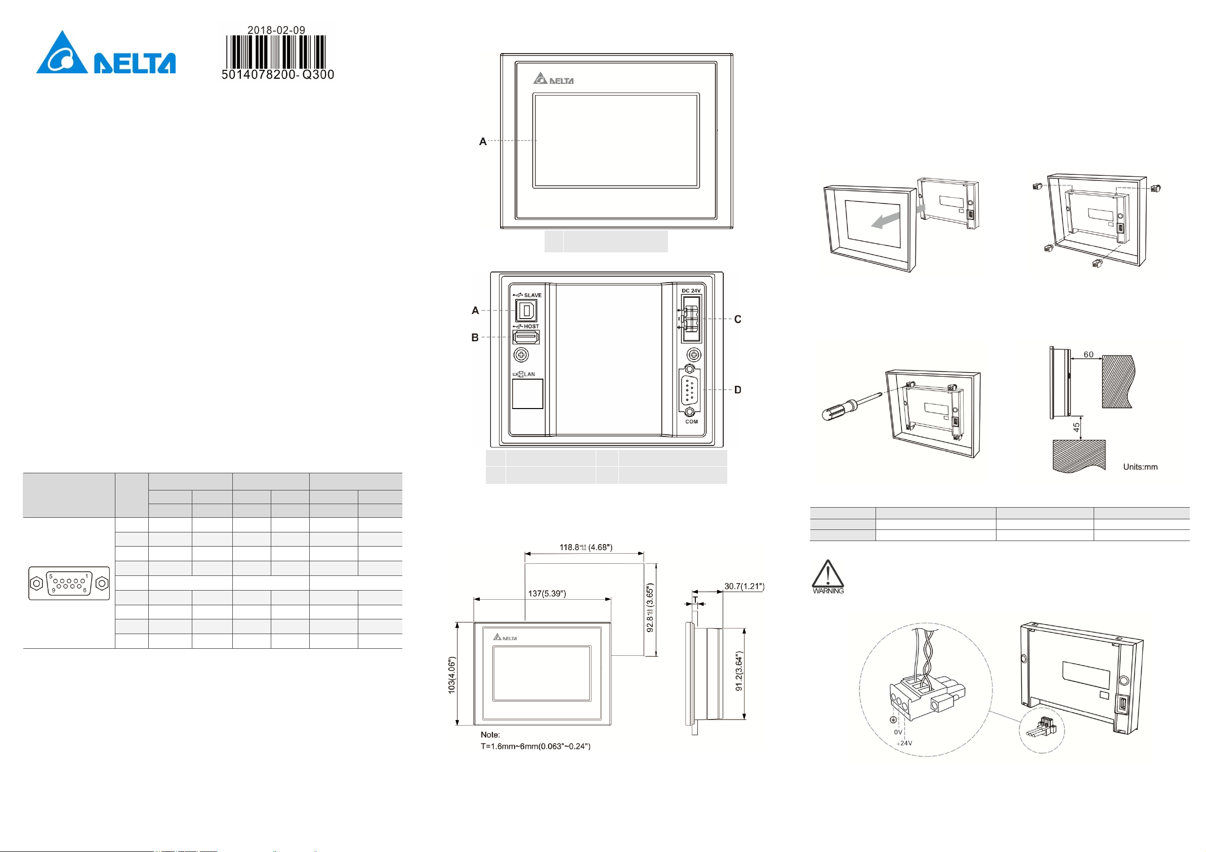
(3) Description of each part
(5) Installation and wiring
DOP-103BQ
Instruction Sheet
(1) General precautions
Thank you for purchasing this product. This instruction sheet provides information about the DOP-100
series HMI. Before using this product, please read through this instruction sheet carefully to ensure the
correct use of the product. Please keep this sheet handy for quick reference whenever needed. Before
finishing reading this sheet, please follow the instructions below:
Install the product in an indoor location, which is free of vapor, corrosive and inflammable gas and
liquids.
Please refer to the wiring diagram when connecting the wires.
Ensure your HMI is correctly grounded. The grounding method must comply with the national
electrical standard (please refer to NFPA 70: National Electrical Code, 2005 Ed.).
Do not disassemble the HMI or change the wiring when power is on.
Do not touch the power supply when power is on, or it may cause electric shock.
When the HMI displays a low power notification and requires a battery change, please contact
your local distributor or Delta Customer Service Center for the replacement. Do not change the
batteries by yourself.
This product can be used with other industrial automation equipment. Please read through this
sheet carefully and install the product according to the instructions to avoid danger.
Cleaning method: please use a dry cloth to clean the product.
This product must be used at an altitude below 2,000 m.
If the equipment is used in a manner not specified by the manufacturer, the protection provided by
the equipment may be impaired.
DOP-103BQ (front view)
DOP-103BQ (rear view)
A Operation / display area
Precautions:
Incorrect installation may result in malfunction.
To ensure the HMI is well ventilated, make sure there is sufficient space between the HMI and the
adjacent objects or walls.
This product should be used on a case / platform which conforms to enclosure Type 4X standard (for
indoor use only).
The maximum panel thickness for mounting must be no greater than 5 mm.
Installation steps:
Step 1:
Put the waterproof gasket into the HMI and then
insert the HMI into the panel cutout.
Step 3:
Tighten the screws with the torque less than
0.5 N-M / 0.7 N-M to avoid damage to the plastic
case.
DOP-103BQ torque: 4.41 lb-inch (0.5 N-M)
Step 2:
Place the fasteners into the slots and tighten the
screws until reaching the panel cutouts.
Step 4:
For heat dissipation, please keep a minimum
clearance of 60 mm on the rear of the HMI.
(2) Communication port pin assignment
DOP-103BQ COM port
MODE1 MODE2 MODE3
COM Port Pin
Note: mark “-” means connection is not required.
1 - - D+ - - TXD+
2 RXD - - - RXD -
3 TXD - - - TXD -
4 - D+ - D+ - RXD+
5 GND GND GND
6 - - D- - - TXD-
7 RTS - - - RTS -
8 CTS - - - CTS -
9 - D- - D- - RXD-
COM1 COM2 COM1 COM2 COM1 COM2
RS-232 RS-485 RS-485 RS-485 RS-232 RS-422
A
USB slave
Power input terminal
C
(24 AWG wire min.)
(4) Mounting dimensions
DOP-103BQ
B
D
USB host
COM1
Wiring:
Type Wire gauge (AWG) Stripped length To rq u e
Solid
Stranded
Please refer to the following diagram when wiring the power connector. The temperature
rating of the cable must be greater than 75
24 - 12 7 - 8 mm 5 kg-cm (4.3 lb-in)
24 - 12 7 - 8 mm 5 kg-cm (4.3 lb-in)
o
C (167oF).
Operation temperature: 0
Storage temperature: -20
o
o
C to 50oC (32oF to 122oF)
C to 60oC (-4oF to 140oF)
Page 2

(6) Hardware specifications
Model DOP-103BQ
Panel type 4.3" TFT LCD (65535 colors)
Resolution 480 x 272 pixels
Backlight
Display
Display range 95.04 x 53.856 mm
LED backlight (half-life under room temperature 25oC > 20,000 hours) *1
Brightness 400 cd/m² (Typ.)
CPU
Flash ROM
RAM
Touchscreen
4-wire resistive touchscreen > 1,000,000 operated
ARM Cortex-A8 (800 MHz)
256 Mbytes
256 Mbytes
Buzzer Multi-tone frequency (2 K – 4 KHz) / 80 dB
Network interface N/A
USB 1 USB slave Ver 2.0; 1 USB host Ver 2.0
SD N/A
COM1 RS-232 (supporting flow control) / RS-485*2
Serial
communication
port
COM2
RS-422 / RS-485*2
COM3 N/A
Auxiliary function key N/A
Calendar Built-in
Cooling method Natural cooling
Approvals
Panel waterproof level IP65 / NEMA 4
Operation voltage*2
CE / UL (please use shielding network cable and magnetic ring with the filter of
300 ohm / 100 MHz)
DC +24V (-15% to +15%) (please use an isolated power supply)
Supplied by Class 2 or SELV circuit (isolated from MAINS by double insulation)
Leakage current 500 VAC for 1 minute (between DC24V terminal and FG terminal)
Power consumption*2
Backup battery
Backup battery life
(subject to operation temperature and condition)
5.67W (Max) *3
3V lithium battery CR2032 × 1
About 3 years or more at 25oC
Operation temperature 0oC to 50oC (32oF to 122oF)
Storage temperature -20oC to +60oC (-4oF to 140oF)
Operating environment
Vibration resistance
Shock resistance
Dimension
(W) x (H) x (D) mm
Mounting dimension
(W) x (H) mm
Weight
10% to 90% RH [0oC - 40oC], 10% to 55% RH [41oC - 50oC];
pollution degree: 2
Conforms to IEC61131-2: continuous vibration 5 Hz - 8.3 Hz with amplitude
3.5 mm; 8.3 Hz - 150 Hz with amplitude 1G
Conforms to IEC60068-2-27:
11 ms, 15 G Peak, in X, Y, Z directions each for 6 times
137 x 103 x 37.1
118.8 x 92.8
Approx. 280g
Note:
1. The half-life of the backlight is defined as the maximum luminance being reduced by 50% when the
maximum drive current is supplied to the HMI. The life of LED backlight shown here is estimated at the
room temperature of 25
2. The withstand voltage of the isolated power circuit is 1500V peak for 1 minute.
3. The HMI power consumption is the power consumed when the HMI is not connecting with other
peripheral devices. To ensure normal operation of the HMI, the recommended capacity of the power
supply is 1.5 to 2 times of the specified power consumption.
4. Isolated power supply is recommended.
5.
6. DOP-100 series can be used with other industrial automation equip
sheet carefully and install the product according to the instructions to avoid danger.
o
C with ambient humidity.
ent. Please read through this
m
 Loading...