

2011-01-08
50 11 69 47 01 -2 CE 1

PLEASE READ PRIOR TO INSTALLATION FOR SAFETY.
AC input power must be disconnected before any wiring to the AC motor drive
is made.
DANGER
Even if the power has been turned off, a charge may still remain in the DC-link
capacitors with hazardous voltages before the POWER LED is OFF. Please do
not touch the internal circuit and components.
There are highly sensitive MOS components on the printed circuit boards.
These components are especially sensitive to static electricity. Please do not
touch these components or the circuit boards before taking anti-static
measures. Never reassemble internal components or wiring.
Ground the AC motor drive using the ground terminal. The grounding method
must comply with the laws of the country where the AC motor drive is to be
installed.
DO NOT install the AC motor drive in a place subjected to high temperature,
direct sunlight and inflammables.
Never connect the AC motor drive output terminals U/T1, V/T2 and W/T3
CAU TION
directly to the AC mains circuit power supply.
Only qualified persons are allowed to install, wire and maintain the AC motor
drives.
Even if the 3-phase AC motor is stop, a charge may still remain in the main
circuit terminals of the AC motor drive with hazardous voltages.
If the AC motor drive is stored in no charge condition for more than 3 months,
the ambient temperature should not be higher than 30 °C. Storage longer than
one year is not recommended, it could result in the degradation of the
electrolytic capacitors.
NOTE
The content of this manual may be revised without prior notice. Please consult our distributors or download the most updated
version at http://www.delta.com.tw/industrialautomation

Table of Contents
SUMMARY OF UPDATES .............................................................................................................0-1
CHAPTER 1 INTRODUCTION.......................................................................................................1-1
CHAPTER 2 INSTALLATION .......................................................................................................2-1
CHAPTER 3 UNPACKING.............................................................................................................3-1
CHAPTER 4 WIRING.....................................................................................................................4-1
CHAPTER 5 MAIN CIRCUIT TERMINALS ..................................................................................5-1
CHPATER 6 CONTROL TERMINALS...........................................................................................6-1
CHAPTER 7 OPTIONAL ACCESSORIES ..................................................................................7-1
CHAPTER 8 OPTION CARDS.......................................................................................................8-1
CHAPTER 9 SPECIFICATION.......................................................................................................9-1
CHAPTER 10 DIGITAL KEYPAD.................................................................................................10-1
CHAPTER 11 SUMMARPY OF PARAMETERS..........................................................................11-1
CHPAPTER 12 DESCRIPTION OF PARAMETER SETTINGS...................................................12-1
CHAPTER 13 WARNING CODES...............................................................................................13-1
CHAPTER 14 FAULT CODES AND DESCRIPTIONS.................................................................14-1
CHAPTER 15 CANOPEN OVERVIEW........................................................................................15-1
CHAPTER 16 PLC FUNCTION....................................................................................................16-1
Application
Control BD V1.00;
Keypad V1.00;

Summary of UpdatesC2000 Series
r
Summary of Updates
The following changes summarize the differences to the C2000 Simplified Manual, Version
5011694700.
Chatpers Changes Detail
[Table of Content] New New Chapters:
• Chapter 2 Installation
• Chapter 7 Optional Accessories
• Chapter 12 Description of Parameter Settings
• Chapter 15 CANopen Overview
• Chapter 16 PLC Function
• (Applicable model, AC motor drive selection)
Applicable model
AC motor drive selection
[01 Introduction]
[03 Unpacking] New FRAME F~H
[04Wiring] New RB-RC power protection system diagram
Updates Wiring diagram 1, 2
[05 Main circuit terminal]
[06 Control circuit
terminal]
[08 Option cards] New Steps to remove key cover
New Frame FRAME A~H
KPC-CC01 digital keypad
Update Serial number
New Mounting clearances and wiring information [02 Installation]
Update Unpacking details moved to CH3
FRAME H secure the drive
FRAME F~H lifting weight
Control circuit description
Figure1,2
Figure 3 FRAME E-H DC-LINK
New Main circuit terminal specification FRAME F~H
Update
Update Control terminal specification: wire gauge, torque,
Main circuit terminal diagram 3
Terminal signs +1, - and description
Main circuit terminal specifications
Frame A~E (max. and min. wire gauge,torque, note, diagram)
Steps to removes the key cover and wiring New
Removable terminal block figure
Descripton and factory settings: MI11~MI8 terminals, SG+ & SG- terminals
Steps to remove the terminal block
EMC-D611A I/O & Relay extension card
EMC-PG01L PG card and wiring diagrams(can be operate by
Pr.10-00~10-02)
EMC-PG01O PG card and wiring diagrams(can be operate by
Pr.10-00~10-02)
EMC-PG01U:
description, wiring diagram, terminal Screw Sepecifications
EMC-PG01R:
description, wiring diagram, terminal Screw Sepecifications
CMC-MOD01:
feature, product file, CMC-MOD01 installation to C2000, p arameter setting fo
Ethernet, removal, basic register, LED indicator& troubleshoots
CMC-PD01:
feature, product file, installation, LED indicator& troubleshoots
CMC-DN01:
feature, product file, LED indicator& troubleshoots
CMC-EIP01:
feature, product file, installation, Connecting CMC-EIP01 to VFD-C2000,
parameter setting for Ethernet, removal, basic register, LED indicator&
troubleshoots
0-1

[09 Specification]
[10 Digital Keypad]
[11 Summary of
Parameters]
EMC-COP01: RJ45 Pin definition, Specifi cation
Update RJ45 (Socket) for digital keypad
Option card diagrams for Slot 1~3
EMC-D42A: Descriptons for COM and MI10~MI13
EMC-R6AA: Description
EMC-PG01O PG OUT V+, V-, A/O, B/O, Z/O
Remove ABZ1 Encoder signal type, AB2 Pulse signal type
New
230V FRAME F specification
460V FRAME F~H specification
Operation temperature and protection level
Update
230V/460V
Nomal load: carrier frequency
Operational voltage range
230V
EMC Filter EMI Filter
460V EMI Filter Description and Note
Control method
Certification
Delete
230V/460V
Heavy load& Normal load: load capacity and max. output frequency (Hz)
Torque characteristic
Overload capacity
Ambient temperature
*Reduced by 2%Irated/1℃
New Digital Keypad: KPC-CC01 Function
Update
Keypad picture
Descriptions of Keypad Functions
Change LED keypad to KPC-CE01
CANopen~”RUN”
CANopen~”ERR”
ONLY LED change to KPC-CE01
Remove Digital keypad operation procedure
New
Parameters
Group 00
Pr.00-00 Settings: 39, 41, 43, 45, 47, 49, 51, 93
Pr.00-04 Settings: 2~8, 21,24~31
Pr 00-05
Pr.00-25~Pr.00-50
Pr.01-46
Pr.02-54
Pr.03-31~03-33
Pr.04-30~04-44
Group 5
Pr.05-00 Settings: 4, 5, 6, 12
Pr.05-33~05-43
Pr.06-17~06-22 Settings: 66~107, 111
Pr.06-55~06-73
Pr.10-22
Pr.11-41~11-46
Update Goup 00
Pr00-09 Reserved
Pr.00-10 Settings: 1~3
Pr.00-11 Settings: 0~5
Pr. 00-12 point-to-p oint po sition mode
Pr.00-13 Settings: 0~2
Pr.00-14 Reserved
Pr.00-17
Normal load 230V (460V)
1-15HP [1-20HP] 2~15KHz
20-50HP [25-100HP] 2~10KHz
60-100HP [125-475HP] 2~09KHz
Heavy load
1-475HP 2~6KHz
0-2

Summary of UpdatesC2000 Series
Pr.00-19 PLC Command Mask
Pr.00-20 Source of Master Frequency Command(AUTO)
Pr.00-21 Settings: 0~5
Pr.00-24 Memory of Frequen cy Command
Pr. 02-01~02-08 Settings: 6, 10, 18, 31~33, 35, 37, 41~47, 49, 54~70
Pr.00-14 Reserved
Group 01
Pr. 01-02~01-06, 01-20~01-21, 01-36~01-40: Factory Settings
Goup 02
Pr.02-09 1: up/down constant speed (Pr.02-10)
Pr.02-11
Pr.02-13~02-17 Settings: 10, 13, 14, 39, 40, 43~49, 51, 52
Pr.02-19 Terminal counting value attained (returns to 0)
Pr.02-20 Preliminary counting value attained (not return to 0)
Pr.02-33 Output Current Level Setting for Multi-function External Terminals
Pr.02-34
Pr.02-35
Pr.02-37
Pr.02-48
Goup 03
Pr.03-00~03-02 Settings: 1 1, 12~17, 18~19
Pr.03-10
Pr.03-20~03-23 Settings: 19~23
Pr.03-26~03-30
Factory settings in 03-20~03-23, 03-21 03-24
Group 04
Pr.04-15~04-29
Group 05
Pr.05-01 Settings: 10~120% of drive’s rated current
Pr.05-06~05-09, 05-18~05-21 setting range
Pr.05-12~05-13
Group 06
Pr.06-00~06-01
Pr.06-03~06-04
Pr.06-07
Pr.06-10
Pr.06-12
Pr.06-17~06-22 Settings: 15, 17,19,20,21,25,28,29,32,39,40,52,53,64,65
Pr.06-31~06-54
Group 07
Pr.07-05
Pr.07-07
Pr.07-10
Pr.07-24~07-27
Pr.07-29
Pr.07-31~07-33
Group 08
Pr.08-00
Pr.08-20
Group 09
Pr.09-30
Pr.09-35
Pr.09-37~09-39
Pr.09-43
Pr.09-45
Group 10
Pr.10-00
Pr.10-17~10-18
Pr.10-21
Group 11
Pr.11-00
Pr.11-03~11-06
Pr.11-08
0-3

[13 Warning Codes]
[14 Fault Codes and
Descriptions]
Pr.11-10
Pr.11-24
Pr.11-28~11-34
Pr.11-40
Remove Pr. 01-47~01-50
New LCM display screen example
Error code:
“SE3”, “PGFB”, “Cldn”, “Cadn”, “CFrn”, “PLSF”, “PCGd”, “PCbF”, “PCnL”,
“PCCt”, “PCSF”, “PCSd”, “PCAd”, “Ecby”
Update LED display content
“ANL” description
Remove LCM display example
All display icons
New Fault display screen example
Fault code:
“ovA”, “ovd”, “ovn”, “ovS”, “PWR”, “uC”, “LMIT”, “ryF”, “PGF5”, “ocU”, “ocV”,
“OPHL”, “OPHL”, “OPHL”, “TRAP”
Update LCM display icons
Fault codes:
“CE1”, “CE2”, “CE3”, “CE4”, “CE10”, “CP10” ,
“dEb”, “Uocc” A, “Vocc” B, “Wocc” C
Remove LED display content
Fault code:
“UC1”, “UC2”
0-4
Chapter 1 IntroductionC2000 Series
Chapter 1 Introduction
Receiving and Inspection
After receiving the AC motor drive, please check for the following:
1. Please inspect the unit after unpacking to assure it was not damaged during shipment.
2. Make sure that the part number printed on the package corresponds with the part number indicated
on the nameplate.
3. Make sure that the voltage for the wiring lie within the range as indicated on the nameplate.
4. Please install the AC motor drive according to this manual.
5. Before applying the power, please make sure that all the devices, including power, motor, control
board and digital keypad, are connected correctly.
6. When wiring the AC motor drive, please make sure that the wiring of input terminals “R/L1, S/L2,
T/L3” and output terminals”U/T1, V/T2, W/T3” are correct to prevent drive damage.
7. When power is applied, select the language and set the parameter groups via the digital keypad
(KPC-CC01).
8. After applying the power, please trial run with the low speed and then increase the speed gradually
to the desired speed.
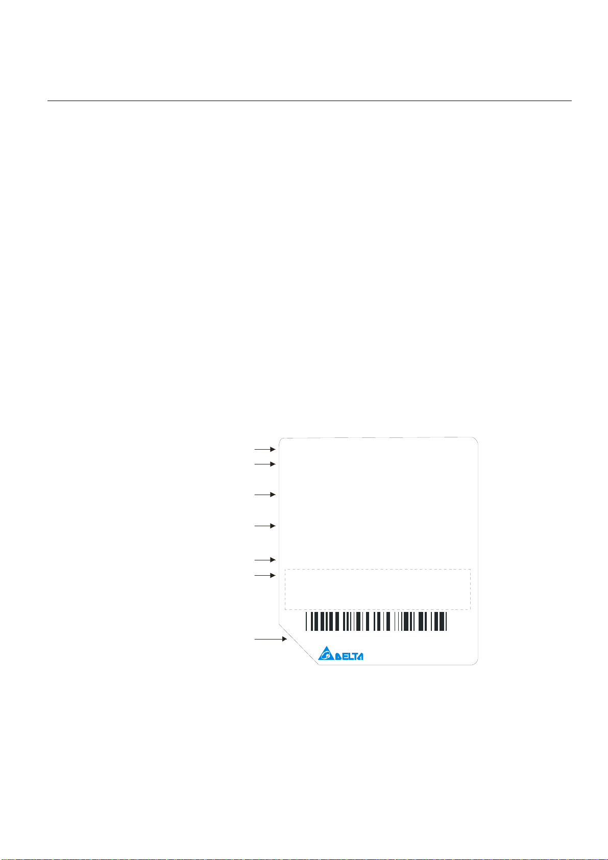
Nameplate Information
AC Drive Model
Input Voltage/Current
Output Voltage/Current
Frequency Range
Firmware Vers ion
Certifications
MODEL:VFD007C43A
INPUT:
Normal Duty: 3PH 380-480V 5 0/60Hz 4 .3A
Heavy Duty: 3PH 38 0-480V 50/60Hz 4.1A
OUTPU T:
Normal Dut y: 3PH 0-480V 3A 2.4KVA 1HP
Heavy Duty: 3PH 0-4 80V 2.9A 2.3KVA 1HP
FREQUENCY RANGE:
Normal Du t y: 0- 600H z
Heavy Duty: 0-300Hz
Versi on:
V0.30
Serial Number
007C43A7T9300002
DE LTA ELECTR ONIC S. INC.
MADE IN XXXXXXX
1-1
W
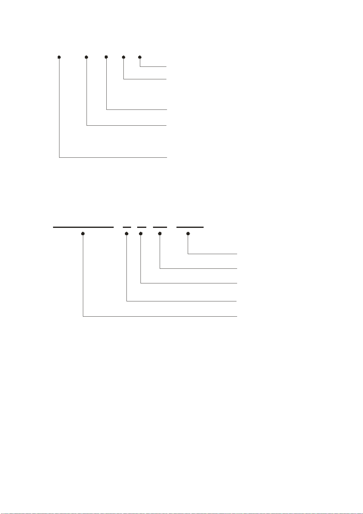
Chapter 1 IntroductionC2000 Series
Model Name
VFD007C43A
Version type
Input voltage
23:230V 3-PHASE
43:460V 3-PHASE
C2000 series
Applicable motor capacity
007:1HP(0.75kW)~ 3350:475HP(335k
Refer to the specifications for details
Serial Number
007C43A0 T 9 30 0002
Series name(Variable Frequency Drive)
T: Tauyuan W: Wujian
S: Shanghai
460V 3-PHASE 1HP(0.75kW)
Production number
Production week
Production year
Production factory
Model number
1-2
Chapter 1 IntroductionC2000 Series
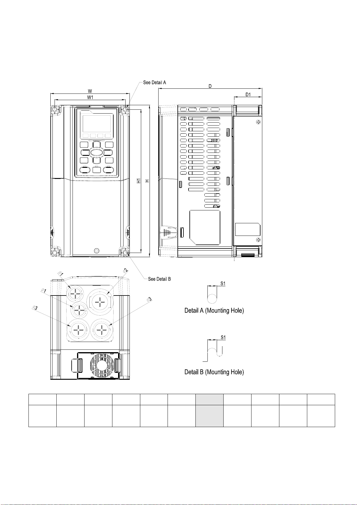
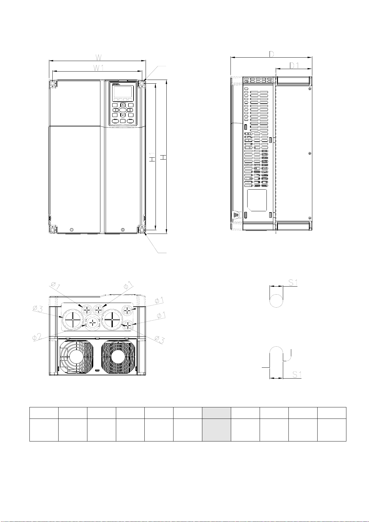
Dimensions
Frame A
VFD007C23A; VFD007C43A/E; VFD015C23A; VFD015C43A/E; VFD022C23A; VFD022C43A/E;
VFD037C23A; VFD037C43A/E; VFD040C43A/E; FD055C43A/E
Unit: mm [inch]
Frame
A1
NOTE: Model VFD007C43E; VFD015C43E; VFD022C43E; VFD037C43E; VFD040C43E; VFD055C43E will be available for
W H D W1 H1
130.0
[5.12]
ordering soon. Please contact your local distributor or Delta representative for detailed launch schedule.
250.0
[9.84]
170.0
[6.69]
116.0
[4.57]
236.0
[9.29]
1-3
D1* S1 Φ1 Φ2 Φ3
45.8
[1.80]
6.2
[0.24]
22.2
[0.87]
34.0
[1.34]
D1*: Flange mounting
28.0
[1.10]

Chapter 1 IntroductionC2000 Series
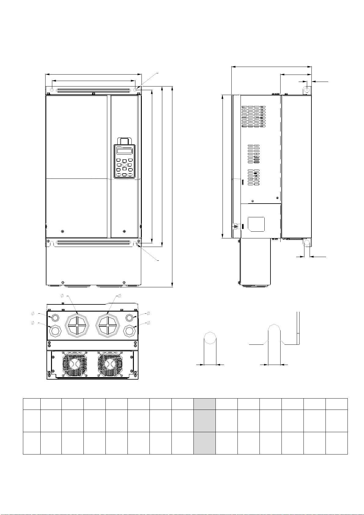
Frame B
VFD055C23A; VFD075C23A; VFD075C43A/E; VFD110C23A; VFD110C43A/E; VFD150C43A/E
See Detail A
Frame
B1
See Detail B
W H D W1 H1
190.0
[7.48]
320.0
[12.60]
190.0
[7.48]
173.0
[6.81]
303.0
[11.93]
Detail A (Mounting Hole)
Detail B (Mounting Hole)
Unit: mm [inch]
D1* S1 Φ1 Φ2 Φ3
77.9
[3.07]
8.5
[0.33]
22.2
[0.87]
34.0
[1.34]
28.0
[1.10]
D1*: Flange mounting
NOTE: Model VFD075C43E; VFD110C43E; VFD150C43E will be available for ordering soon. Please contact your local distributor
or Delta representative for detailed launch schedule.
1-4
Chapter 1 IntroductionC2000 Series
Frame C
VFD150C23A; VFD185C23A; VFD185C43A/E; VFD220C23A; VFD220C43A/E; VFD300C43A/E
See Detail A
Frame
C1
See Detail B
W H D W1 H1
250.0
[9.84]
400.0
[15.75]
210.0
[8.27]
231.0
[9.09]
381.0
[15.00]
Detail A (Mounting Hole)
Detail B (Mounting Hole)
Unit: mm [inch]
D1* S1 Φ1 Φ2 Φ3
92.9
[3.66]
8.5
[0.33]
22.2
[0.87]
34.0
[1.34]
50.0
[1.97]
D1*: Flange mounting
NOTE: Mode VFD185C43E; VFD220C43E; VFD300C43E will be available for ordering soon. Please contact your local
distributor or Delta representative for detailed launch schedule.
1-5
Chapter 1 IntroductionC2000 Series
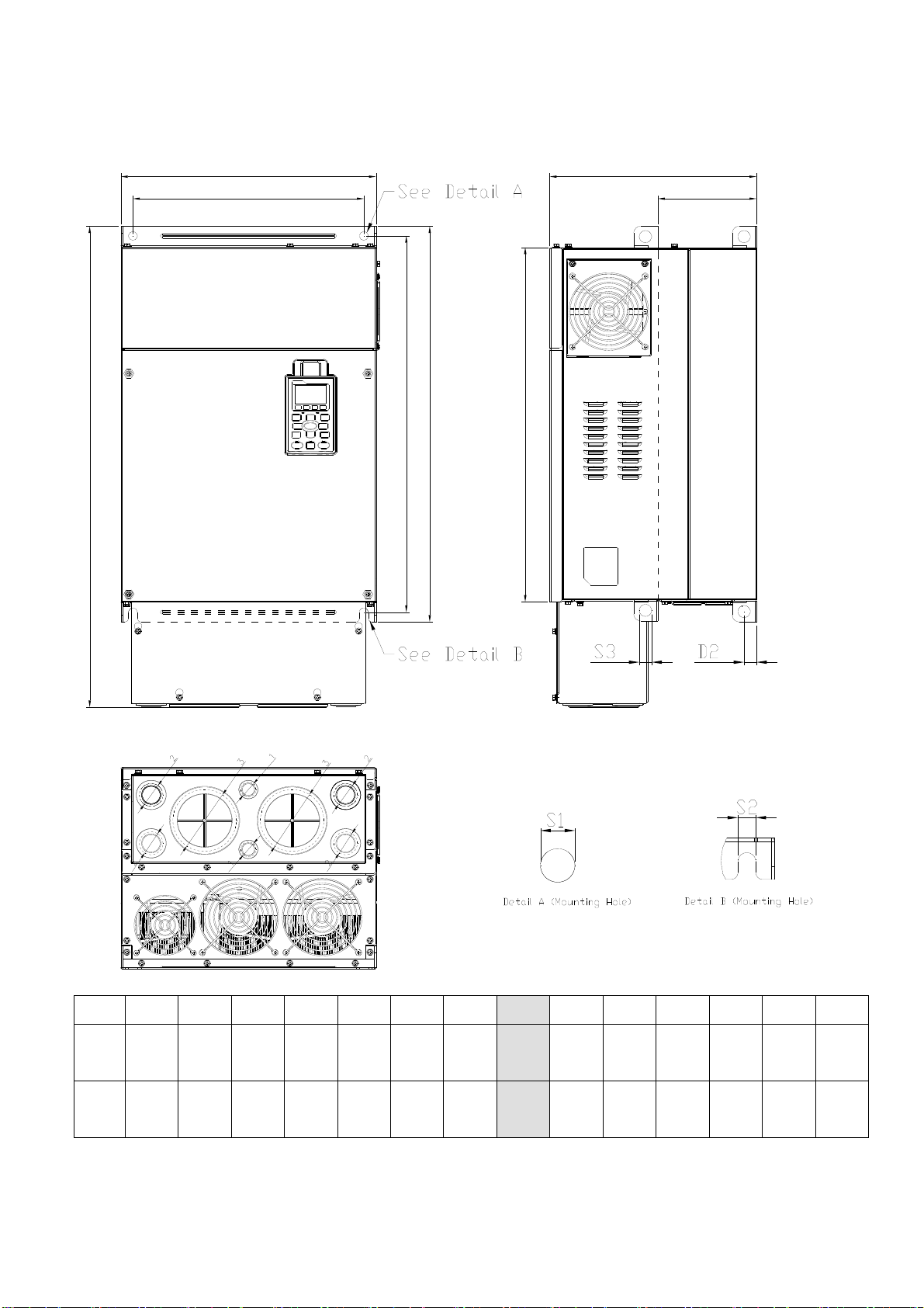
Frame D
D1: VFD300C23A; VFD370C23A; VFD370C43A; VFD450C43A; VFD550C43A; VFD750C43A
D2: VFD300C23E; VFD370C23E; VFD370C43E; VFD450C43E; VFD550C43E; VFD750C43E
D
W
W1
SEE DETAIL A
D1
D2
H2
H1
H3
H
S2
SEE DETAIL B
1
3
2
1
3
2
S1S1
DETAIL A
(MOUNTING HOLE)
DETAIL B
(MOUNTING HOLE)
Unit: mm [inch]
Frame W H D W1 H1 H2 H3 D1* D2 S1 S2 Φ1 Φ2 Φ3
330.0
D1
[12.99]
330.0
D2
[12.99]
- 275.0
[10.83]
688.3
[27.10]
275.0
[10.83]
285.0
[11.22]
285.0
[11.22]
550.0
[21.65]
550.0
[21.65]
525.0
[20.67]
525.0
[20.67]
492.0
[19.37]
492.0
[19.37]
1-6
107.2
[4.22]
107.2
[4.22]
16.0
[0.63]
16.0
[0.63]
11. 0
[0.43]
11. 0
[0.43]
18.0
[0.71]
18.0
[0.71]
- - -
76.2
[3.00]
D1*: Flange mounting
34.0
[1.34]
22.0
[0.87]
Chapter 1 IntroductionC2000 Series
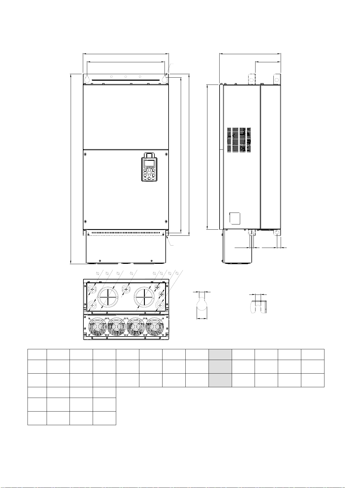
Frame E
E1: VFD450C23A; VFD550C23A; VFD750C23A; VFD900C43A; VFD1100C43A
E2: VFD450C23E; VFD550C23E; VFD750C23E; VFD900C43E; VFD1100C43E
W
W1
H1
H2
H
H3
D
D1
Frame
E1
E2
?
?
W H D W1 H1 H2 H3
370.0
?
?
300.0
?
335.0
?
?
?
589
560.0
528.0
-
[14.57]
370.0
[14.57]
715.8
[28.18]
[11.81]
300.0
[11.81]
[13.19
335.0
[13.19
[23.19]
589
[23.19]
[22.05]
560.0
[22.05]
[20.80]
528.0
[20.80]
Unit: mm [inch]
D1* D2 S1, S2 S3 ψ1 ψ2 ψ3
143.0
[5.63]
143.0
[5.63]
18.0
[0.71]
18.0
[0.71]
13.0
[0.51]
13.0
[0.51]
18.0
[0.71]
18.0
[0.71]
- - -
22.0
[0.87]
34.0
[1.34]
D1*: Flange mounting
92.0
[3.62]
1-7
Chapter 1 IntroductionC2000 Series
Frame F
F1: VFD900C23A; VFD1320C43A; VFD1600C43A; F2: VFD900C23E; VFD1320C43E; VFD1600C43E
See Detail A
W
W1
H
See Detail A
H1
H2
H3
D
D1
Frame
F1
F2
Frame
F1
F2
See Detail B
2
1
2
2
W H D W1 H1 H2 H3
420.0
[16.54]
420.0
[16.54]
ψ1 ψ2 ψ3
92.0
[3.62]
92.0
[3.62]
300.0
[11.81]
940.0
[37.00]
35.0
[1.38]
35.0
[1.38]
300.0
[11.81]
22.0
[0.87]
22.0
[0.87]
380.0
[14.96]
380.0
[14.96]
800.0
[31.50]
800.0
[31.50]
1
3
3
2
Detail A (Mounting Hole)
770.0
[30.32]
770.0
[30.32]
717.0
[28.23]
717.0
[28.23]
S1
S2
S3
Detail B (Mounting Hole)
D2
S1
Unit: mm [inch]
D1* D2 S1 S2 S3
124.0
[4.88]
124.0
[4.88]
18.0
[0.71]
18.0
[0.71]
13.0
[0.51]
13.0
[0.51]
25.0
[0.98]
25.0
[0.98]
D1*: Flange mounting
18.0
[0.71]
18.0
[0.71]
1-8
Chapter 1 IntroductionC2000 Series
Frame G
G1: VFD1850C43A; VFD2200C43A; G2: VFD1850C43E; VFD2200C43E
W
W1
D
H2
H1
H
H3
S3
Frame
G1
G2
Unit: mm [inch]
W H D W1 H1 H2 H3 S1 S2 S3 ψ1 ψ2 ψ3
500.0
[19.69]
500.0
[19.69]
1240.2
[48.83]
-
397.0
[15.63]
397.0
[15.63]
440.0
[217.32]
440.0
[217.32]
1000.0
[39.37]
1000.0
[39.37]
963.0
[37.91]
963.0
[37.91]
913.6
[35.97]
913.6
[35.97]
1-9
13.0
[0.51]
13.0
[0.51]
26.5
[1.04]
26.5
[1.04]
27.0
[1.06]
27.0
[1.06]
- - -
22.0
[0.87]
34.0
[1.34]
117.5
[4.63]
Chapter 1 IntroductionC2000 Series
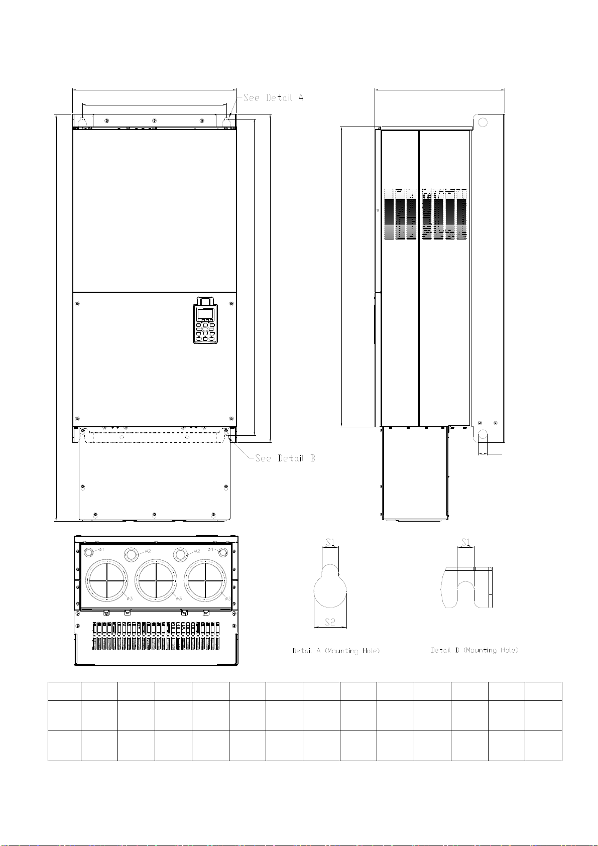
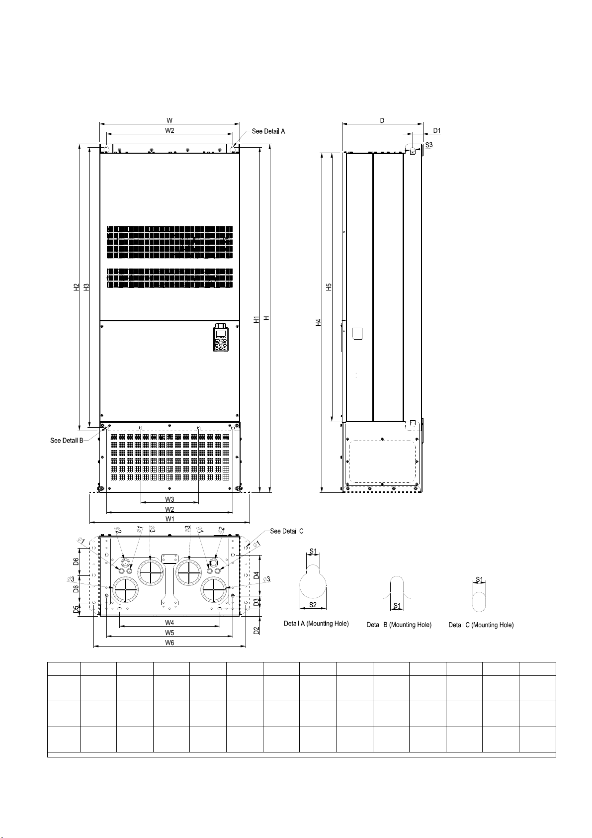
Frame H
H1: VFD2800C43A; VFD3150C43A; VFD3550C43A
H2: VFD2800C43E-1; VFD3150C43E-1; VFD3550C43E-1
H3: VFD2800C43E; VFD3150C43E; VFD3550C43E
Frame
H1
H2
H3
Unit: mm [inch]
W H D W1 W2 W3 W4 W5 W6 H1 H2 H3 H4
700.0
[27.56]
700.0
[27.56]
700.0
[27.56]
1745.0
[68.70]
1745.0
[68.70]
-
398.0
[15.67]
404.0
[15.91]
404.0
[15.91]
-
800.0
[31.50]
800.0
[31.50]
630.0
[24.80]
290.0
[11.42]
- -
- -
- - - -
500.0
[19.69]
500.0
[19.69]
1-10
630.0
[24.80]
630.0
[24.80]
760.0
[29.92]
760.0
[29.92]
1729.0
[68.07]
1729.0
[68.07]
1435.0
[56.50]
1403.0
[55.24]
- -
- -
-
1701.6
[66.99]
1701.6
[66.99]

Chapter 1 IntroductionC2000 Series
Frame H5 D1 D2 D3 D4 D5 D6 S1 S2 S3 ψ1 ψ2 ψ3
1346.6
H1
[53.02]
1346.6
H2
[53.02]
1346.6
H3
[53.02]
45.0
[1.77]
51.0
[2.01]
51.0
[2.01]
- - - - -
[1.50]
[1.50]
38.0
38.0
[2.56]
[2.56]
65.0
65.0
204.0
[8.03]
204.0
[8.03]
68.0
[2.68]
68.0
[2.68]
137.0
[5.39]
137.0
[5.39]
13.0
[0.51]
13.0
[0.51]
13.0
[0.51]
26.5
[1.04]
26.5
[1.04]
26.5
[1.04]
25.0
[0.98]
25.0
[0.98]
25.0
[0.98]
- - -
- - -
[0.87]
22.0
[1.34]
34.0
117.5
[4.63]
1-11
Chapter 1 IntroductionC2000 Series
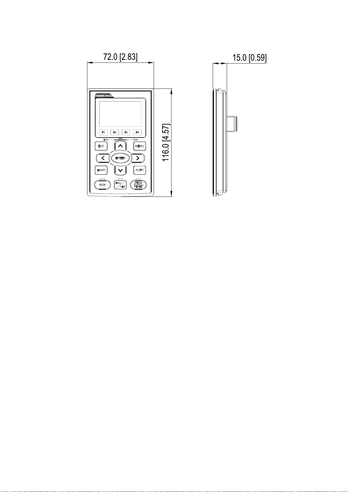
Digital Keypad
KPC-CC01
1-12

Chapter 2 InstallationC2000 Series
Chapter 2 Installation
The appearances shown in the following figures are for reference only.
Airflow direction: (Blue arrow) inflow (Red arrow) outflow
Single drive: installation
(Frame A-H)
Side-by-side installation(Frame A-C)
Multiple drives: side-by-side installation(Frame A,B,C, G, H)
Multiple drives: side-by-side installation (Frame D, E, F) Install a barrier between the drives.
2-1
f
Chapter 2 InstallationC2000 Series
Multiple drives side-by-side installation in rows (Frame A,B,C )
Ta: Frame A~G Ta*: Frame H
For installation in rows, it is recommended installing a barrier between the drives. Adjust the size/depth o
the barrier till the temperature measured at the fan’s inflow side is lower than the operation temperature.
Operation temperature is the defined as the temperature measured 50mm away from the fan’s inflow
side. (As shown in the figure below)
Minimum mounting clearance
Frame A (mm) B (mm) C (mm) D (mm)
A~C 60 30 10 0
D~F 100 50 - 0
G 200 100 - 0
H 350 0 0
200 (100, Ta=40℃)
Frame A VFD007C23A; VFD007C43A/E; VFD015C23A; VFD015C43A/E; VFD022C23A;
VFD022C43A/E; VFD037C23A; VFD037C43A/E; VFD040C43A/E; VFD055C43A/E;
Frame B VFD055C23A; VFD75C23A; VFD075C43A/E; VFD110C23A; VFD110C43A/E;
VFD150C43A/E;
Frame C VFD150C23A; VFD185C23A; VFD185C43A/E; VFD220C23A; VFD220C43A/E;
VFD300C43A/E;
Frame D VFD300C23A/E; VFD370C23A/E; VFD370C43A/E; VFD450C43A/E; VFD550C43A/E;
VFD750C43A/E;
Frame E VFD450C23A/E; VFD550C23A/E; VFD750C23A/E; VFD900C43A/E; VFD1100C43A/E;
Frame F VFD900C23A/E; VFD1320C43A/E; VFD1600C43A/E;
Frame G VFD1850C43A; VFD2200C43A; VFD1850C43E; VFD2200C43E;
Frame H VFD2800C43A; VFD3150C43A; VFD3550C43A; VFD2800C43E-1; VFD3150C43E-1;
VFD3550C43E-1;VFD2800C43E; VFD3150C43E; VFD3550C43E;
NOTE
1. It is the minimum distance required for frame A~D. If drives are installed closer than the minimum mounting clearance, the
fan may not function properly.
2. Model VFD007C43E; VFD015C43E; VFD022C43E; VFD037C43E; VFD040C43E; VFD055C43E; VFD075C43E;
VFD110C43E; VFD150C43E; VFD185C43E; VFD220C43E; VFD300C43E will be available for ordering soon. Please
contact your local distributor or Delta representative for detailed launch schedule,
2-2
Chapter 2 InstallationC2000 Series
NOT E
※ The mounting clearances shown in the left figure are NOT for installing the
drive in a confined space (such as cabinet or electric box). When installing
in a confined space, besides the same minimum mounting clearances, it
needs to have the ventilation equipment or air conditioner to keep the
surrounding temperature lower than the operation temperature.
※ The following table shows heat dissipation and the required air
volume when installing a single drive in a confined space. When
installing multiple drives, the required air volume shall be multiplied
by the number the drives.
※ Refer to the chart (Air flow rate for cooling) for ventilation equipment
design and selection.
※ Refer to the chart (Power dissipation) for air conditioner design and
Air flow rate for cooling
selection.
Power dissipation of AC motor
drive
Flow Rate (cfm) Flow Rate (m3/hr) Power Dissipation
Model No.
External Internal Total External Internal Total
Loss External
(Heat sink)
Internal Total
VFD007C23A - - - - - - 33 27 61
VFD015C23A 14 - 14 24 - 24 56 31 88
VFD022C23A 14 - 14 24 - 24 79 36 115
VFD037C23A 10 - 10 17 - 17 113 46 159
VFD055C23A 40 14 54 68 24 92 197 67 264
VFD075C23A 66 14 80 112 24 136 249 86 335
VFD110C23A 58 14 73 99 24 124 409 121 529
VFD150C23A 166 12 178 282 20 302 455 161 616
VFD185C23A 166 12 178 282 20 302 549 184 733
VFD220C23A 146 12 158 248 20 268 649 216 865
VFD300C23A/E 179 30 209 304 51 355 913 186 1099
VFD370C23A/E 179 30 209 304 51 355 1091 220 1311
VFD450C23A/E 228 73 301 387 124 511 1251 267 1518
VFD550C23A/E 228 73 301 387 124 511 1401 308 1709
VFD750C23A/E 246 73 319 418 124 542 1770 369 2139
VFD900C23A/E 224 112 336 381 190 571 2304 484 2788
VFD007C43A/E - - - - - - 33 25 59
VFD015C43A/E - - - - - - 45 29 74
VFD022C43A/E 14 - 14 24 - 24 71 33 104
VFD037C43A/E 10 - 10 17 - 17 103 38 141
VFD040C43A/E 10 - 10 17 - 17 116 42 158
VFD055C43A/E 10 - 10 17 - 17 134 46 180
VFD075C43A/E 40 14 54 68 24 92 216 76 292
VFD110C43A/E 66 14 80 112 24 136 287 93 380
VFD150C43A/E 58 14 73 99 24 124 396 122 518
VFD185C43A/E 99 21 120 168 36 204 369 138 507
VFD220C43A/E 99 21 120 168 36 204 476 158 635
VFD300C43A/E 126 21 147 214 36 250 655 211 866
VFD370C43A/E 179 30 209 304 51 355 809 184 993
VFD450C43A/E 179 30 209 304 51 355 929 218 1147
VFD550C43A/E 179 30 209 304 51 355 1156 257 1413
2-3
R
%
R
%
Chapter 2 InstallationC2000 Series
Air flow rate for cooling
Power dissipation of AC motor
drive
Flow Rate (cfm) Flow Rate (m3/hr) Power Dissipation
Model No.
External Internal Total External Internal Total
Loss External
(Heat sink)
Internal Total
VFD750C43A/E 186 30 216 316 51 367 1408 334 1742
VFD900C43A/E 257 73 330 437 124 561 1693 399 2092
VFD1100C43A/E 223 73 296 379 124 503 2107 491 2599
VFD1320C43A/E 224 112 336 381 190 571 2502 579 3081
VFD1600C43A/E 289 112 401 491 190 681 3096 687 3783
VFD1850C43A/E 454 771 4589
VFD2200C43A/E 454 771 5772
VFD2800C43A/E 769 1307 6381
VFD3150C43A/E 769 1307 7156
VFD3550C43A/E
※ The required airflow shown in chart is for installing single drive in a
769
1307
confined space.
※ When installing the multiple drives, the required air volume should
be the required air volume for single drive X the number of the
drives.
※ Model VFD007C43E; VFD015C43E; VFD022C43E; VFD037C43E;
VFD040C43E; VFD055C43E; VFD075C43E; VFD110C43E;
VFD150C43E; VFD185C43E; VFD220C43E; VFD300C43E will be
available for ordering soon. Please contact your local distributor or
Delta representative for detailed launch schedule.
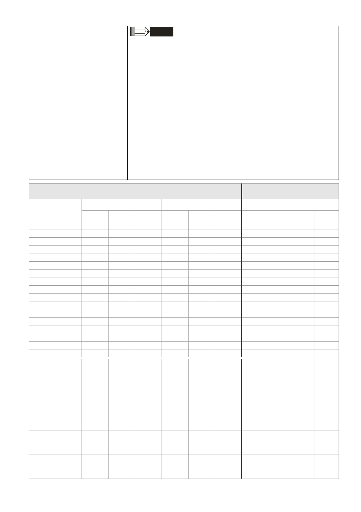
Derating curve diagram: Normal Duty
Setting =1
Setting = 0 or 2
(50℃: UL open-type)
(40℃:UL type1 or open type_size by size)
460V
Setting = 0 or 2
(40℃: UL open-type)
(30℃: UL type1 or open type_size by size)
460V
8007
※ The heat dissipation shown
in the chart is for installing
single drive in a confined
space.
※ When installing the multiple
drives, volume of heat
dissipation should be the
heat dissipated for single
drive X the number of the
drives.
※ Heat dissipation for each
model is calculated by rated
voltage, current and default
carrier.
110
100
)
90
ati o(
80
70
60
4 5 6 7 8 9 10 11 12 13 14 15
Setting =1
Setting = 0 or 2
VFD007 ~1 50 C4 3A/ E
VFD185 ~5 50 C4 3A/ E
VFD750~3 550C43A/E
Fc (kHz)
VFD007 ~1 50 C4 3A/E
VFD185 ~5 50 C4 3A/E
VFD750 ~3 55 0C 43 A/ E
110
100
)
90
80
atio(
70
60
4 5 6 7 8 9 101112131415
Fc (kHz )
Setting = 0 or 2
2-4
R
%
R
%
R
%
R
%
R
%
R
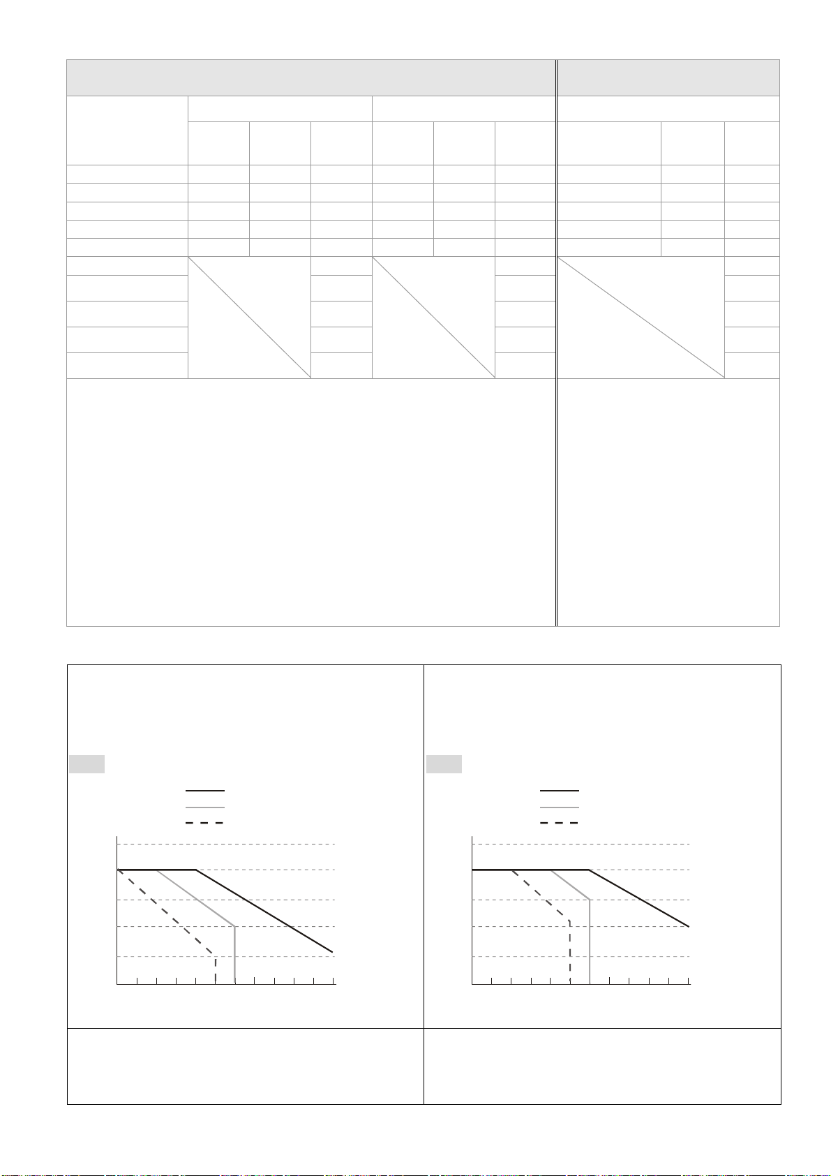
230V
110
100
)
atio(
(50℃: UL open-type)
(40℃:UL type1 or open type_size by size)
VFD007 ~110C23A
VFD150 ~ 37 0C23A;
VFD300 ~ 37 0C23E
VFD450 ~ 90 0C23A/E
90
80
70
230V
110
100
)
atio(
Chapter 2 InstallationC2000 Series
(40℃: UL open-type)
(30℃: UL type1 or open type_size by size)
VFD007 ~110C23A
VFD150 ~3 70 C2 3A ;
VFD300 ~3 70 C2 3E
VFD450 ~9 00 C2 3A /E
90
80
60
4 5 6 7 8 9 10 11 12 13 14 15
Fc (kHz)
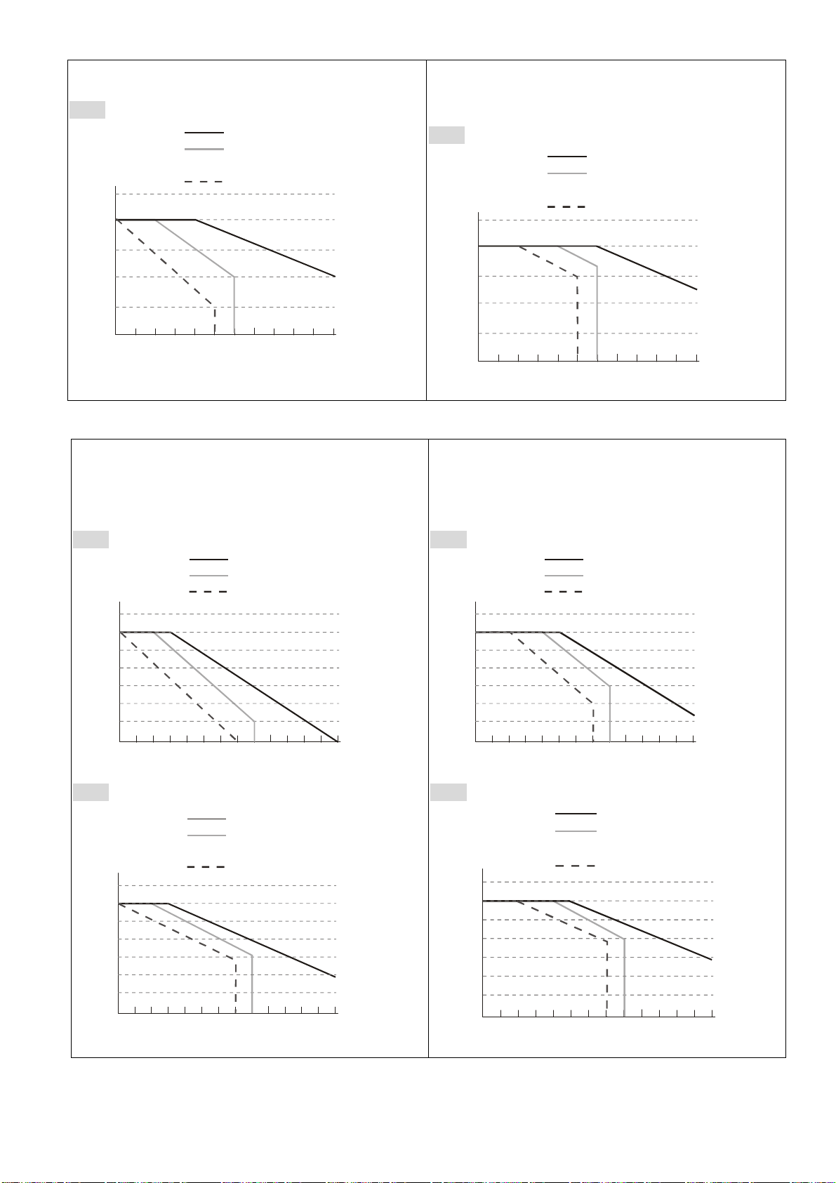
Derating curve diagram: Heavy Duty
Setting =1
Setting = 0 or 2
(50℃: UL open-type)
(40℃: UL type1 or open type_size by size)
460V
VFD007 ~1 50 C4 3A/ E
VFD185 ~5 50 C4 3A/ E
VFD750~3 550C43A/E
110
100
)
90
80
atio(
70
60
50
40
3
2 5 6 7 8 9 10 11 12 13 14 15
4
Fc (kHz)
230V
VFD007~110C23A
VFD150~3 70 C2 3A;
VFD300~3 70 C2 3E
VFD450~9 00 C2 3A/ E
110
100
)
90
80
70
atio(
60
50
40
2 5 6 7 8 9101112131415
3
4
Fc (kHz)
70
60
4 5 6 7 8 9 10 11 12 13 14 15
Fc (kHz)
Setting = 0 or 2
(40℃: UL open-type)
(30℃: UL type1 or open type_size by size)
460V
VFD007 ~1 50 C43A/E
VFD185 ~5 50 C43A/E
VFD750 ~3 55 0C 43 A/ E
110
100
)
90
80
70
atio(
60
50
40
3
2 5 6 7 8 9 10 11 12 13 14 15
4
Fc (kHz)
230V
VFD007 ~110C23A
VFD150 ~3 70 C2 3A;
VFD300 ~3 70 C2 3E
VFD450 ~9 00 C2 3A/ E
110
100
90
80
70
atio(%)
60
50
40
2 5 6 7 8 9101112131415
3
4
Fc (kHz)
2-5
Chapter 3 UnpackingC2000 Series
Chapter 3 Unpacking
The AC motor drive should be kept in the shipping carton or crate before installation. In order to retain the
warranty coverage, the AC motor drive should be stored properly when it is not to be used for an
extended period of time.
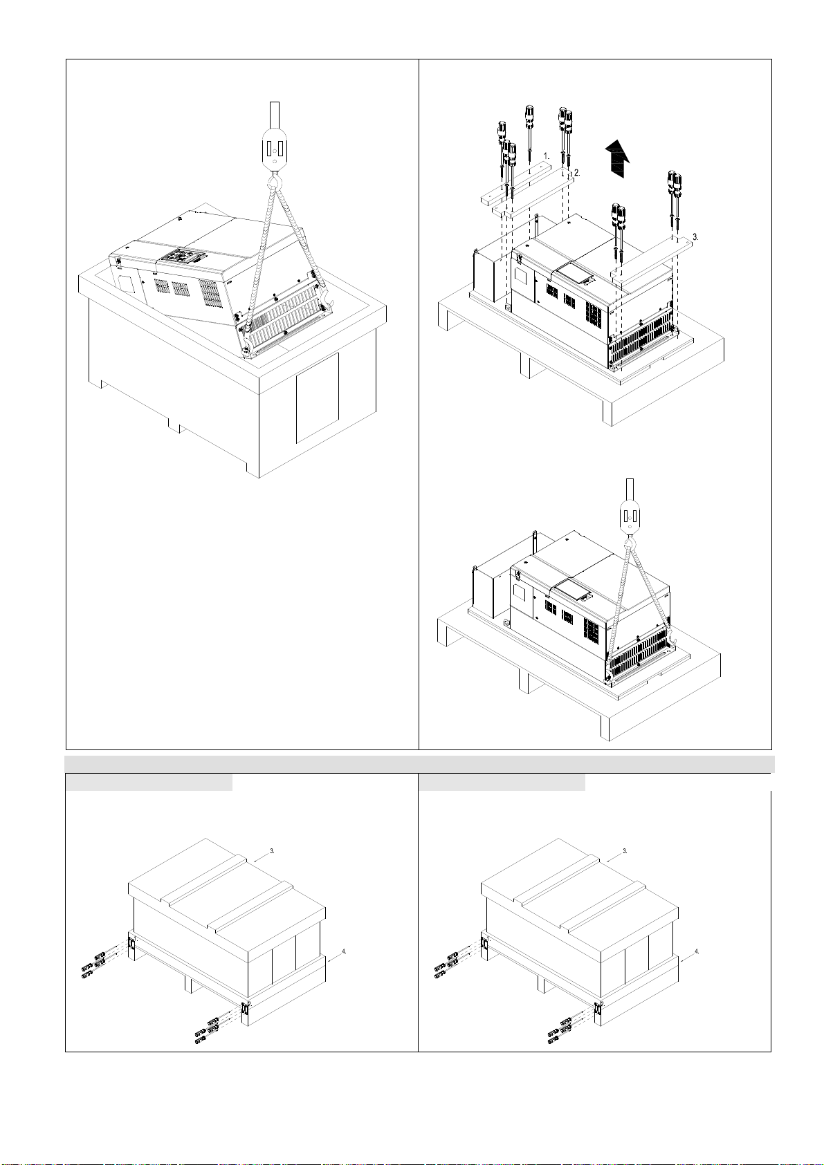
The AC motor drive is packed in the crate. Follows the following step for unpack:
Frame D
Crate 1 (VFDXXXCXXA) Crate 2 (VFDXXXCXXE)
Loosen the 12 cover screws to open the crate.
Loosen all of the screws on the 4 iron plates at the
four bottom corners of the crate. 4 screws on each
of the iron plate.
Remove the EPEs and manual.
Loosen the 8 screws that fastened on the pallet,
remove the wooden plate.
Remove the crate cover, EPEs, rubber and
manual.
3-1
Chapter 3 UnpackingC2000 Series
Lift the drive by hooking the lifting hole. It is now
ready for installation.
Loosen the 10 screws on the pallet, remove the
wooden plate.
Lift the drive by hooking the lifting hole. It is now
ready for installation.
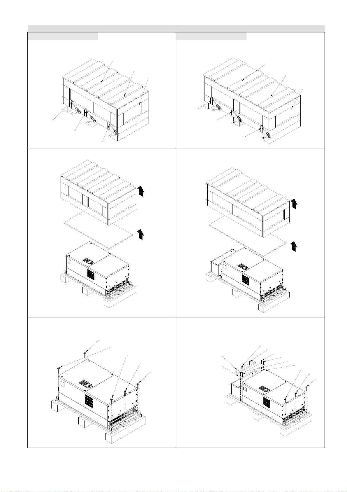
Frame E
Crate 1 (VFDXXXCXXA) Crate 2 (VFDXXXCXXE)
Loosen the 4 screws on the iron plates. There are
4 iron plates and in total of 16 screws.
Loosen the 4 screws on the iron plates. There are
4 iron plates and in total of 16 screws.
3-2

Chapter 3 UnpackingC2000 Series
Remove the crate cover, EPEs and manual.
Remove the crate cover, EPEs, rubbers and
manual.
Loosen the 8 screws on the pallet as shown in the
following figure.
Lift the drive by hooking the lifting hole. It is now
ready for installation.
Loosen the 10 screws on the pallet and remove the
wooden plate.
Lift the drive by hooking the lifting hole. It is now
ready for installation.
3-3
Chapter 3 UnpackingC2000 Series
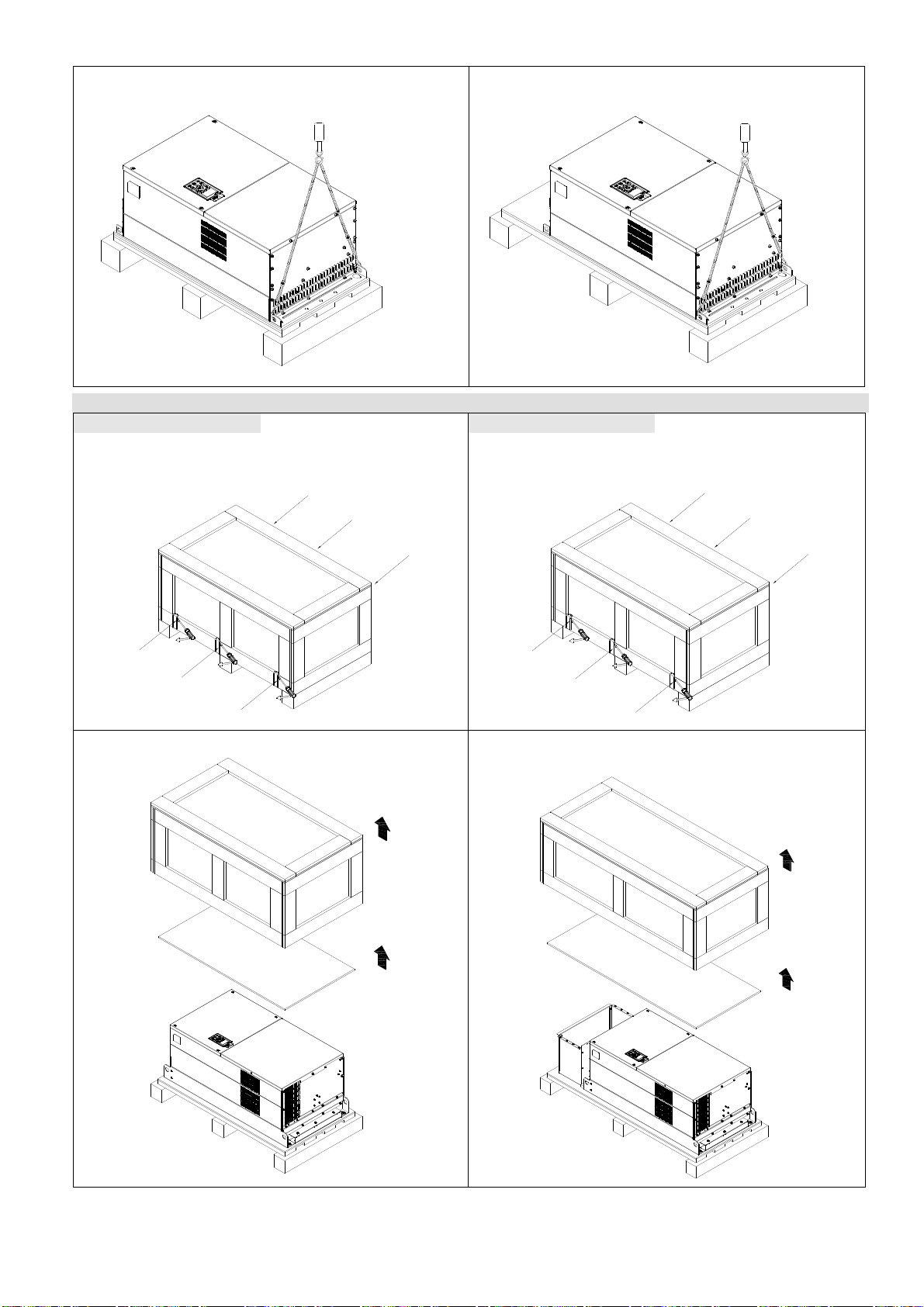
Frame F
Crate 1 (VFDXXXCXXA) Crate 2 (VFDXXXCXXE)
Remove the 6 clips on the side of the crate with a
flat-head screwdriver. (As shown in figure below.)
Remove the 6 clips on the side of the crate with a
flat-head screwdriver. (As shown in figure below.)
6
5
4
1
2
3
Remove the crate cover, EPEs and manual.
6
5
4
1
2
3
Remove the crate cover, EPEs, rubbers and
manual.
Loosen the 5 screws on the pallet
as shown in the following figure.
5
4
Loosen the 9 screws on the pallet and remove the
wooden plate.
9
8
3
2
wood plate2
wood plate1
1
7
6
5
4
3
2
1
3-4
6
6
Chapter 3 UnpackingC2000 Series
Lift the drive by hooking the lifting hole. It is now
ready for installation
.
Lift the drive by hooking the lifting hole. It is now
ready for installation.
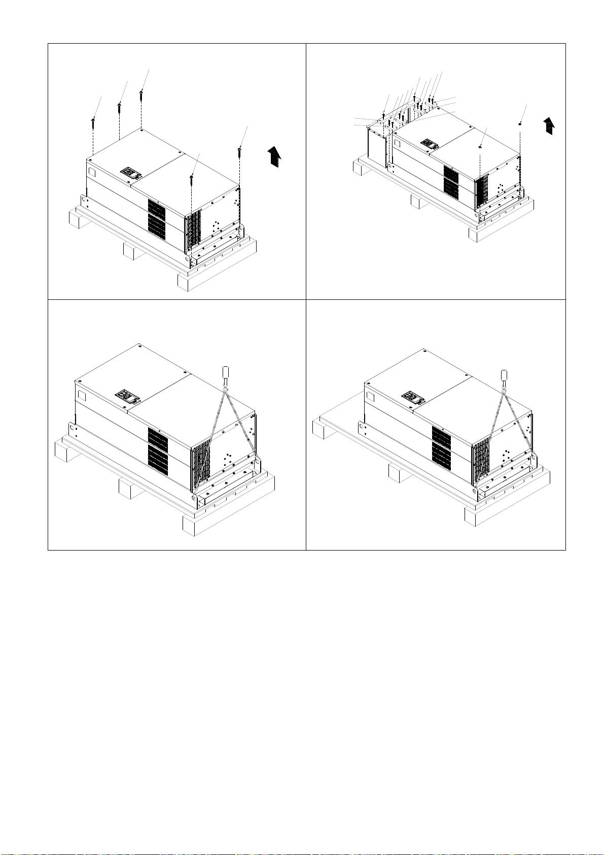
Frame G
Crate 1 (VFDXXXCXXA) Crate 2 (VFDXXXCXXE)
Remove the 6 clips on the side of the crate with a
flathead screwdriver. (As shown in figure below.)
4
5
Remove the 6 clips on the side of the crate with a
flathead screwdriver. (As shown in figure below.)
4
5
1
2
3
Remove the crate cover, EPEs and manual.
1
2
3
Remove the crate cover, EPEs, rubber and manual.
3-5
Chapter 3 UnpackingC2000 Series
Loosen the 5 screws as shown in following figure:
3
4
5
1
2
Lift the drive by hooking the lifting hole. It is now
ready for installation.
Loosen the 9 screws and remove the wooden plate.
3
4
11
5
6
7
8
9
12
wood plate5
wood plate4
10
wood plate1
wood plate2
wood plate3
2
Lift the drive by hooking the lifting hole. It is now
ready for installation.
1
3-6

Chapter 3 UnpackingC2000 Series
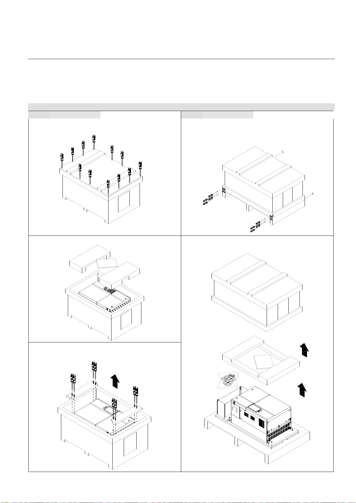
Frame H
Crate 1 (VFDXXXCXXA) Crate 2 (VFDXXXCXXE-1)
Remove the 8 clips on the side of the crate with a
flathead screwdriver. (As shown in figure below.)
Remove the 8 clips on the side of the crate with a
flathead screwdriver. (As shown in figure below.)
Remove the crate cover, EPEs and manual.
Loosen the 6 screws on the top then remove 6
metal washers and 6 plastic washers as shown in
figure below.
Remove the crate cover, EPEs, rubbers and
manual.
Loosen the 6 screws on the top then remove 6
metal washers and 6 plastic washers as shown in
figure below.
3-7

Chapter 3 UnpackingC2000 Series
Lift the drive by hooking the lifting hole. It is now
ready for installation.
Loosen 6 of the M6 screws on the side and remove
the 2 plates, as shown in below. The removed
screws and plates can be used to secure the AC
motor drive from the external.
Secure the drive from the external. (Skip to the
next step if it is not necessary in your case.)
Loosen 8 of M8 screws on the both sides and place
the 2 plates that were removed from the last step.
Fix the plates to AC motor drive by fasten 8 of the
M8 screws. (As shown in below)
Torque: 150~180kg-cm (130.20~156.24lb-in.)
Lift the drive by hooking the lifting hole. It is now
ready for installation.
3-8

Chapter 3 UnpackingC2000 Series
Frame H
Crate 3 (VFDXXXCXXE)
Use flathead screwdriver to remove the clips on the side of the crate, 8 clips in total.
Remove the crate cover, EPEs, rubber and manual.
Loosen the 6 screws on the cover, remove 6 metal washers and 6 plastic washers as shown in below:
3-9

Chapter 3 UnpackingC2000 Series
Loosen 6 of the M6 screws on the side and removes the 2 plates, as shown in following figure. The
removed screws and plates can be used to secure AC motor drive from the external.
Secure the drive from the internal.
Loosen 18 of the M6 screws and remove the top
cover as shown in figure 2. Mount the cover (figure
1) back to the drive by fasten the M6 screws to the
two sides of the drive, as shown in figure 2.
Torque: 35~45kg-cm (30.38~39.06lb-in.)
Secure the drive from the external.
Loosen 8 of the M8 screws on the both sides and
place the 2 plates that were removed from the last
step. Fix the plates to rive by fasten 8 of the M8
screws. (As shown in figure below).
Torque: 150~180kg-cm (130.20~156.24lb-in.)
Figure 1
Top cover (Use M12 screws)
Figure 2
3-10

Chapter 3 UnpackingC2000 Series
Fasten 6 of the M6 screws that were removed from last step back to the AC motor drive. As shown in
figure below:
Lift the drive by hooking the lifting hole. It is now ready for installation.
Frame H Secure the drive
(VFDXXXCXXA)
Screw: M12*6
Torque: 340-420kg-cm [295.1-364.6lb-in.]
3-1 1

Chapter 3 UnpackingC2000 Series
(VFDXXXCXXE) & (VFDXXXCXXE-1)
Secure the drive from internal.
Screw: M12*8
Torque: 340-420kg-cm [295.1-364.6lb-in.]
Secure the drive from the external.
Screw: M12*8
Torque: 340-420kg-cm [295.1-364.6lb-in.]
3-12

The Lifting Hook
The arrows indicate the lifting holes, as in figure below: (Frame D~H).
Chapter 3 UnpackingC2000 Series
D
G
Figure 1
E
Figure 2
F
Figure 3
Figure 4
Figure 5
3-13

Chapter 3 UnpackingC2000 Series
Ensure the lifting hook properly goes through the
lifting hole, as shown in the following diagram.
(Applicable for Frame D~G)
(Applicable to Frame H)
Ensure the angle between the lifting holes and the
lifting device is within the specification, as shown
in the following diagram.
(Applicable to Frame H)
3-14

Weight
Chapter 3 UnpackingC2000 Series
VFDXXXXCXXA VFDXXXXCXXE
VFDXXXXCXXA VFDXXXXCXXE
VFDXXXXCXXA
37.6 kg(82.9 Ibs.)
D
63.6 kg(140.2 Ibs.)
E
85kg(187.2 Ibs.)
VFDXXXXCXXE
D
E
88kg(193.8 Ibs.)
40 kg(88.2 Ibs.)
66 kg(145.5 Ibs.)
VFDXXXXCXXA
130kg(286.5 Ibs.) 138kg(303.9 lbs)
VFDXXXXCXXE
H1: VFD2800C43A; VFD3150C43A; VFD3550C43A; 235kg (518.1lbs)
H2: VFD2800C43E-1; VFD3150C43E-1; VFD3550C43E-1; 257kg (566.6lbs)
3-15

Chapter 3 UnpackingC2000 Series
H3: VFD2800C43E; VFD3150C43E; VFD3550C43E; 263kg (579.8lbs)
3-16

Chapter 4 WiringC2000 Series
Chapter 4 Wiring
Wiring Diagram for Frame A~C
* It provides 3-phase power
Fuse/NFB(No Fuse Breaker)
R(L1)
S(L2)
T(L3)
Recommended Ci rcuit
when power supply
is turned OFF by a
fault output.
If the fa ult occurs, the
contact will be ON to turn off the
power and prot ect the power system.
OFF
Factory setting:
NPN (SINK) Mode
Please refe r to
following figure
for wiring of NPN
mode and PNP
mode.
Factory
setting
FWD/STOP
REV/STOP
Multi-step 1
Multi-step 2
Multi-step 3
Multi-step 4
N/A
N/A
N/A
N/A
NOTE
* MI8 can input pulses 100kHz
* Don't apply t he mains voltage directly
to above terminals.
Main circuit
(power) terminals
Control terminals
Digital Signal Common
power removal safety function
for EN954-1 and IEC/EN61508
Digital Signal Common
3
5K
2
1
Analog Signal Common
Modbus RS-485
CAN BUS
Pin 1~2, 7, 8: reserved
Pin 3, 6:GND
Pin 4:SGPin 5:SG+
MC
ON
MC
+10V/20mA
0~1 0V/ 0~2 0mA
4~2 0mA/0~10V
-10~+10V
-10V/20mA
SA
SG+
SG-
Jumper
-
R(L1)
S(L2)
T(L3)
RB
RC
+24V
COM
FWD
REV
MI1
MI2
MI3
MI4
MI5
MI6
MI7
MI8
DCM
S1
SCM
+10V
AVI
ACI
AUI
ACM
-10V
81
DC choke
(optional)
+2
81
Brake resistor
(optional)
+1
B1
Option
Slot 1
Option
Slot 2
Option
Slot 3
B2
U(T1)
V(T2)
W(T3)
RA1
RB1
RC1
RA2
RB2
RC2
AFM1
ACM
AFM2
Motor
IM
3~
Multi-function output terminals
250V ac/5A (N.O. )
250Vac/3A (N.C.)
250Vac/2A (N.O.)
Estimate at COS (0.4)
250Vac/1.2A (N.C.)
Estimate at COS (0.4)
30V dc/5A (N.O.)
30V dc/3A (N.C.)
Multi-function output
Multi-function output
DFM
frequency terminals
frequency terminals
30V30mA 100kHz
DCM
Multi-function output
MO1
frequency terminals
48V/50mA
Mult i-function output
MO2
frequency termina ls
48V/50mA
Multi-function
MCM
Photocoulper Output
Analog Multi-f unction
Outpu t Terminal
0~10VDC/-10~+10V
Analog Signal common
Analog Multi-f unct ion
Outpu t Te rminal
0~10VDC/4~20mA
IO
exte nsi on card
PG
exte nsi on card
IO &RELAY
exte nsi on card
Shielded leads & Cable
4-1

Chapter 4 WiringC2000 Series
Wiring diagram for frame D and above
* It provides 3-phase power
Please refer to Figure 3
Fuse/NFB(No Fuse Breaker)
R(L1)
S(L2)
T(L3)
Recommen ded Circuit
when power supply
is turned OFF by a
fault output.
If the fault occurs, the
contact will be ON to turn off the
power and protect the power s ystem.
Factory setting: NPN (SINK) Mode
Please refer to
following figure
for wiring of NPN
mode and PNP
mode.
* Do not apply the mains voltage directly
to above terminals.
Extern al Power I nput
Factory
setting
* Mi8 can input pulses 100kHz
OFF
FWD/STOP
REV/STOP
E.F.
JOG
Multi-step 1
Multi-step 2
Multi-step 3
Multi-step 4
RESET
Accel/Decel prohibit
Digital Signal Common
3
5K
1
Analog Signal Common
SA
MC
ON
MC
+10V 20mA
0 t o 1 0 V
2
4~2 0mA
-10~+10V
Power supply
-10V 20mA
R(L1)
S(L2)
T(L3)
RB
RC
24V
COM
FWD
REV
MI1
MI2
MI3
MI4
MI5
MI6
MI7
MI8
DCM
+10V
AVI
ACI
AUI
ACM
-10V
+/DC+
-/DC-
U(T1)
V(T2)
W(T3)
RA1
RB1
RC1
RA2
RB2
RC2
DFM
DCM
MO1
MO2
MCM
AFM1
ACM
AFM2
Motor
IM
3~
Multiple-function output
termi nals
250VAC/5A (N.O.)
250VAC/3A (N.O.)
250VAC/2A (N.O.)
Estimate at COS(0.4)
250VAC/1.2A (N.C.)
Estimate at COS(0.4)
30VAC/5A (N.O.)
30VAC/3A (N.C.)
Multi- func tion frequency
output terminals
30V30mA 100kHz
Multi- func tion frequency
output terminals
48V50 mA
Multi- func tion frequency
output terminals
48V50 mA
Multi- func tion
Photocoulper Output
Analog Multi-function
Output T erminal
0~10VD C/-10~+10V
Analog Signal common
Analog Multi-function
Output T ermi na
0~10VD C/4~2mA
Main circuit
(power) terminals
Control circuit terminals
Shielded leads & Cable
Modbus RS-485
CAN BUS
Pin 1~2,7,8:Reserved
Pin 3,6:GND
Pin 4:SGPin 5: SG+
IO& RELAY
extension card
SG+
SG-
81
Option
Slot 3
81
4-2
Option
Slot 1
Option
Slot 2
S1
SCM
power r emoval safety function
for EN954-1 and I EC/EN61508
Digital Signal Comm on
Communication
Extension card
PG
extension card

H
Figure 1
Chapter 4 WiringC2000 Series
Input power terminals for frame G and
Provides 3-phase power
Fus e or NFB (non-fuse breaker)
R
R/L11
R
R/L21
S
S/L12
S
S/L22
T
Figure 2
SINK(NPN)/SOURCE(PNP)Mode
1
Sink Mode Source Mode
with internal power (+24VDC)
MI1
T/L13
T/L23
T
2
with internal power (+24VDC)
It pr ovides 12-pulse power
Y
MI1
R/L11
S/L12
T/L13
R/L21
S/L22
T/L23
MI2
~
MI8
+24V
COM
DCM
3
Sink Mode Source Mode
with external power
MI1
MI2
internal circuit
4
with external power
~
MI8
+24V
COM
DCM
COM
+24V
MI1
MI2
MI8
+24V
COM
MI2
~
MI8
internal circuit
~
external power +24V
DCM
internal c ircuit
DCM
external power +24V
4-3
internal circuit

Chapter 4 WiringC2000 Series
Figure 3
Frame E~H, remove terminal r and terminal s before using DC-Link. (As circled in dotted line, uninstall the
gray section and properly store cable r and cable s. Cable r and cable s are not available in optional
accessories, do not dispose them.)
rs
4-4

Figure 1
Chapter 5 Main Circuit TerminalsC2000 Series
Chapter 5 Main Circuit Terminals
For frame A~C
* Provide 3-phase input power
Fuse/NFB (No Fuse Breaker)
R(L1)
S(L2)
T( L3)
Figure 2
For frame A~C
* Provide 3-phase input power
Jumper
-
R(L1)
S( L2)
T( L3)
Jum per
+2
DC choke
(optional)
+1
Brake resistor
(optio nal)
B1
B2
U(T1)
V(T2)
W(T3)
Brake resistor
(optional)
Mo tor
IM
3~
Fuse/NFB(No Fuse Breaker)
R(L1)
S( L2)
T( L3)
-
R(L1)
S( L2)
T( L3)
+2
+1
B1
U(T1)
V(T2)
W(T3)
B2
Mo to r
IM
3~
5-1

H
Chapter 5 Main Circuit TerminalsC2000 Series
Figure 3
Input power terminals for frame G and
Provides 3-phase power
Fus e or NFB (non-fuse breaker)
R
R/L11
R
It pr ovides 12-pulse power
R/L21
S
S/L12
S
S/L22
T
Terminals Descriptions
R/L1, S/L2, T/L3 AC line input terminals 3-phase
U/T1, V/T2, W/T3 AC drive output terminals for connecting 3-phase induction motor
Applicable to frame A~C
+1, +2
Connections for DC reactor to improve the power factor. It needs to remove the
T/L13
T/L23
T
Y
R/L11
S/L12
T/L13
R/L21
S/L22
T/L23
jumper for installation.
Connections for brake unit (VFDB series)
+1/DC+, -/DC-
B1, B2 Connections for brake resistor (optional)
(for 230V models: 22kW, built≦ -in brake unit)
(for 460V models: 30kW, built≦ -in brake unit)
Common DC Bus
Earth connection, please comply with local regulations.
Main power terminals
Do not connect 3-phase model to one-phase power. It is unnecessary to
consider phase-sequence for these terminals R/L1, S/L2 and T/L3.
It is recommended to add a magnetic contactor (MC) in the power input
wiring to cut off power quickly and reduce malfunction when activating
the protection function of the AC motor drive. Both ends of the MC
should have an R-C surge absorber.
Please make sure to fasten the screw of the main circuit terminals to
prevent sparks which is made by the loose screws due to vibration.
Please use voltage and current within the specification.
When using a general GFCI (Ground Fault Circuit Interrupter), select a
current sensor with sensitivity of 200mA or above and not less than
0.1-second operation time to avoid nuisance tripping.
Please use the shield wire or tube for the power wiring and ground the
two ends of the shield wire or tube.
Do NOT run/stop AC motor drives by turning the power ON/OFF.
5-2

Chapter 5 Main Circuit TerminalsC2000 Series
Run/stop AC motor drives by RUN/STOP command via control terminals
or keypad. If you still need to run/stop AC motor drives by turning power
ON/OFF, it is recommended to do so only ONCE per hour.
Output terminals for main circuit
When it needs to install the filter at the output side of terminals U/T1,
V/T2, W/T3 on the AC motor drive. Please use inductance filter. Do not
use phase-compensation capacitors or L-C (Inductance-Capacitance) or
R-C (Resistance-Capacitance), unless approved by Delta.
DO NOT connect phase-compensation capacitors or surge absorbers at
the output terminals of AC motor drives.
Use well-insulated motor, suitable for inverter operation.
Terminals for connecting DC reactor, external brake resistor, external
brake resistor and DC circuit
This is the terminals used to connect the DC reactor to improve the
power factor. For the factory setting, it connects the short-circuit object.
Please remove this short-circuit object before connecting to the DC
reactor.
DC reactor (optional)
+1
Connect a brake resistor or brake unit in applications with frequent
+2
deceleration ramps, short deceleration time, too low brake torque or
requiring increased brake torque.
B ra ke re si stor
Br ake re si stor
(optional )
B1
The external brake resistor should connect to the terminals (B1, B2) of
B2
(opti o nal )
BR
VFDB
+
Brake unit
(option al)
-
AC motor drives.
For those models without built-in brake resistor, please connect external
brake unit and brake resistor (both of them are optional) to increase
brake torque.
When the terminals +1, +2 and - are not used, please leave the terminals
open.
DO NOT connect [+1, -], [+2, -], [+1/DC+, -/DC-] or brake resistor directly
to prevent drive damage.
5-3

Chapter 5 Main Circuit TerminalsC2000 Series
Main Circuit Terminals
Frame A
Main circuit terminals:
R/L1, S/L2, T/L3, U/T1, V/T2, W/T3, , B1, B2, +1, +2, -
Models
Max. Wire
Gauge
Min. Wire Gauge
VFD007C23A 14 AWG (2.1mm2)
VFD015C23A 12 AWG (3.3mm2)
VFD022C23A 10 AWG (5.3mm2)
VFD037C23A 8 AWG (8.4mm2)
VFD007C43A 14 AWG (2.1mm2)
VFD007C43E 14 AWG (2.1mm2)
VFD015C43A 14 AWG (2.1mm2)
VFD015C43E 14 AWG (2.1mm2)
VFD022C43A 14 AWG (2.1mm2)
8 AWG
(8.4mm
2
)
VFD022C43E 14 AWG (2.1mm2)
VFD037C43A 10 AWG (5.3mm2)
VFD037C43E 10 AWG (5.3mm2)
VFD040C43A 10 AWG (5.3mm2)
VFD040C43E 10 AWG (5.3mm2)
VFD055C43A 10 AWG (5.3mm2)
VFD055C43E
10 AWG (5.3mm
2
)
UL installations must use 600V, 75℃ or 90℃ wire. Use copper wire
only.
Torque
(±10%)
M4
20kg-cm
(17.4 lb-in.)
(1.962Nm)
Frame B
Main circuit terminals:
R/L1, S/L2, T/L3, U/T1, V/T2, W/T3, , B1, B2, +1, +2, -
Models
Max. Wire
Gauge
Min. Wire Gauge
VFD055C23A 8 AWG (8.4mm2)
VFD075C23A 6 AWG (13.3mm2)
VFD110C23A 4 AWG (21.2mm2)
VFD075C43A 8 AWG (8.4mm2)
VFD075C43E 10 AWG (5.3mm2)
VFD110C43A 8 AWG (8.4mm2)
4 AWG
(21.2mm
2
)
VFD110C43E 8 AWG (8.4mm2)
VFD150C43A 6 AWG (13.3mm2)
VFD150C43E
8 AWG (8.4mm
2
)
UL installations must use 600V, 75℃ or 90℃ wire. Use copper wire
only.
NOTE
Terminal D+ [+2 & +1]: T orque: 45 kg-cm [39.0lb-in.] (4.415Nm) (±10%)
VFD110C23A must use 600V, 90℃ wire when surrounding temperature
exceeds 45℃.
Torque
(±10%)
M5
35kg-cm
(30.4 lb-in.)
(3.434Nm)
5-4

Chapter 5 Main Circuit TerminalsC2000 Series
Frame C
Frame D
Main circuit terminals:
R/L1, S/L2, T/L3, U/T1, V/T2, W/T3, , B1, B2, +1, +2, -
Models
Max. Wire
Gauge
Min. Wire Gauge
VFD150C23A 1 AWG (42.4mm2)
VFD185C23A 1/0 AWG (53.5mm2)
VFD220C23A 1/0 AWG (53.5mm2)
VFD185C43A 4 AWG (21.2mm2)
VFD185C43E 6 AWG (13.3mm2)
VFD220C43A 4 AWG (21.2mm2)
1/0 AWG
(53.5mm
2
)
VFD220C43E 4 AWG (21.2mm2)
VFD300C43A 2 AWG (33.6mm2)
VFD300C43E
3 AWG (26.7mm
2
)
UL installations must use 600V, 75℃ or 90℃ wire. Use copper wire
only.
NOTE
Terminal D+ [+2 & +1]: T orque: 90 kg-cm [78.2lb-in.] (8.83Nm) (±10%)
VFD220C23A must use 600V, 90℃ wire when surrounding temperature
exceeds 45℃.
Torque
(±10%)
M8
80kg-cm
(69.4 lb-in.)
(7.85Nm)
Main circuit terminals:
R/L1, S/L2, T/L3, U/T1, V/T2, W/T3,
Models
Max. Wire
Gauge
, +1/DC+, -/DC-
Min. Wire Gauge
Torque
(±10%)
VFD300C23A 4/0 AWG (107mm2)
VFD370C23A 250MCM (127mm2)
VFD370C43A 1/0 AWG (53.5mm2)
VFD450C43A 2/0 AWG (67.4mm2)
VFD550C43A 3/0 AWG (85mm2)
VFD750C43A
VFD300C23E 3/0 AWG (85mm2)
VFD370C23E 4/0 AWG (107mm2)
VFD370C43E 1/0 AWG (53.5mm2)
VFD450C43E 1/0 AWG (53.5mm2)
300MCM
(152mm
4/0 AWG.
(107mm
2
)
300MCM (152mm
2
)
2
)
M8
200kg-cm
(173 lb-in.)
(19.62Nm)
VFD550C43E 2/0 AWG (67.4mm2)
VFD750C43E
4/0 AWG (107mm
2
)
1. UL installations must use 600V, 75oC or 90 oC wires. Use copper
wire only.
2. Figure 1 shows the terminal specification.
3. Figure 2 shows the specification of insulated heat shrink tubing
that comply with UL (600C, YDPU2).
Figure 1
Figure 2
5-5
Chapter 5 Main Circuit TerminalsC2000 Series
Frame E
Main circuit terminals:
R/L1, S/L2, T/L3, U/T1, V/T2, W/T3, , +1/DC+, -/DC-
Models
Max. Wire
Gauge
Min. Wire Gauge
Torque
(±10%)
VFD450C23A 1/0AWG*2 (53.5mm2*2)
VFD550C23A 3/0AWG*2 (85mm2*2)
VFD750C23A 4/0 AWG*2 (107mm2*2)
Incorrect installation may
result in damage to option
or inverter.Pleas e r e fer to
operation manual for
installation instructions.
警告
錯誤的安裝將會導
致變頻器及選配品
損壞,安裝前請務
必參閱使用手冊後
才進行裝配。
VFD900C43A 1/0AWG*2 (53.5mm2*2)
VFD1100C43A
VFD450C23E 1/0AWG*2 (53.5mm2*2)
300MCM*2
(152mm
2
*2)
3/0AWG*2 (85mm
2
*2)
M8
200kg-cm
(173 lb-in.)
(19.62Nm)
VFD550C23E 2/0AWG*2 (67.4mm2*2)
VFD750C23E 3/0AWG*2 (85mm2*2)
4/0 AWG*2
(107mm
2
*2)
VFD900C43E 1/0AWG*2 (53.5mm2*2)
VFD1100C43E
2/0AWG*2 (67.4mm
2
*2)
1. UL installations must use 600V, 75oC or 90 oC wires. Use copper
wire only.
2. Specification of grounding wire
: 300MCM [152 mm2]
Torque: M8 180kg-cm (156 lb-in.) (17.64Nm) (±10%), as shown in
Figure 2.
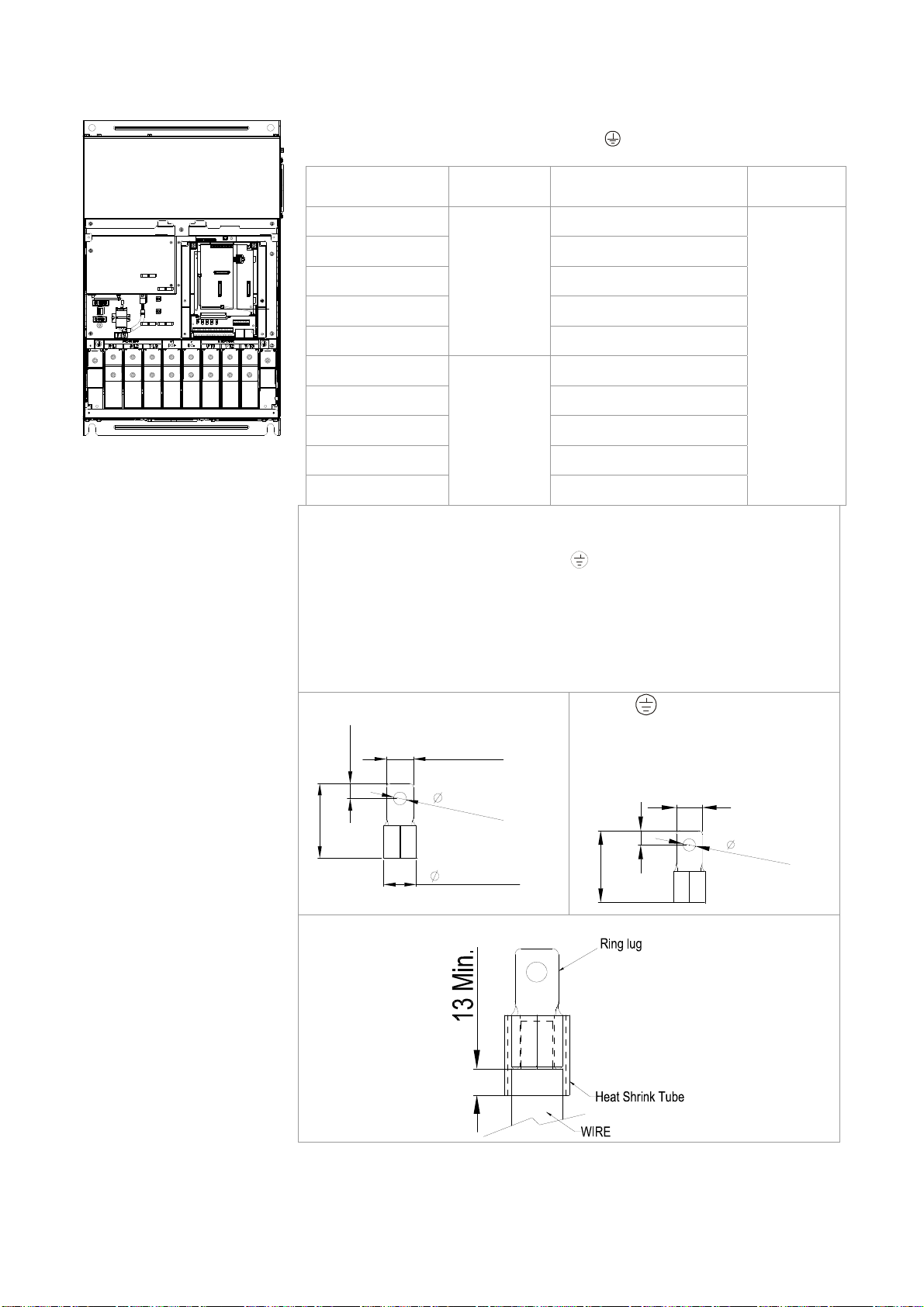
3. Figure 1 shows the specification for ring lug.
4. Figure 3 shows the specification of insulated heat shrink tubing
that comply with UL (600C, YDPU2).
Figure 1
-4
+0
16
31MAX.
8
.
2
M
I
N
Figure 2
.
E
17.0MAX.
28.0MAX.
70MAX.
8
.
2
M
I
N
.
26.5MAX.
65.0MAX.
Figure 3
5-6

Chapter 5 Main Circuit TerminalsC2000 Series
Frame F
Main circuit terminals:
R/L1, S/L2, T/L3, U/T1, V/T2, W/T3, +1/DC+, -/DC-
Models
VFD900C23A 300MCM*2 (152mm2*2)
VFD1320C43A 4/0 AWG*2 (107mm2*2)
VFD1600C43A
VFD900C23E 4/0 AWG*2 (107mm2*2)
VFD1320C43E 3/0AWG*2 (85mm2*2)
VFD1600C43E
1. VFD900C23A/E installations must use 90 wire. ℃
2. For other model, UL installations must use 600V, 75 or 90 ℃℃
wire. Use copper wire only.
3. Specification of grounding wire
Torque: M8 200kg-cm (173 lb-in.) (19.62Nm) (±10%)
5. Figure 1 shows the specification for ring lug.
4. Figure 2 shows the specification of insulated heat shrink tubing
that comply with UL (600C, YDPU2).
Figure 1
Max. Wire
Gauge
300MCM*2
(152mm
4/0 AWG*2
(107mm
2
2
*2)
*2)
Min. Wire Gauge
300MCM*2 (152mm
4/0 AWG*2 (107mm
:300MCM*2 [152 mm2*2]
Figure 2
2
*2)
2
)
200kg-cm
(173 lb-in.)
(19.62Nm)
Torque
(±10%)
M8
-4
+0
16
31MAX.
8
.
2
M
I
N
.
70MAX.
26.5MAX.
5-7

Chapter 5 Main Circuit TerminalsC2000 Series
Frame G
Main circuit terminals:
R/L11, R/L12, S/L21, S/L22, T/L31, T/L32
Models
Max. Wire
Gauge
Min. Wire Gauge
Torque
(±10%)
VFD1850C43A 2/0AWG*4 (67.4mm2*4)
M8
VFD2200C43A 3/0AWG*4 (85mm2*4)
VFD1850C43E 1/0AWG*4 (53.5mm2*4)
VFD2200C43E
300MCM*4
(152mm
2
*4)
2/0AWG*4 (67.4mm
2
*4)
200kg-cm
(173 lb-in.)
(19.62Nm)
Main circuit terminals:
U/T1, V/T2, W/T3, +1/DC+, -/DC-
Models
Max. Wire
Gauge
Min. Wire Gauge
VFD1850C43A 400MCM*2 (203mm2*2)
VFD2200C43A 500MCM*2 (253mm2*2)
VFD1850C43E 300MCM*2 (152mm2*2)
VFD2200C43E
500MCM*2
(253mm
2
*2)
400MCM*2 (203mm
2
*2)
1. UL installations must use 600V, 75 or 90℃℃ wire. Use copper
wire only.
2. Use 600V, 90 wire ℃ for VFD2200C43A when the surrounding
temperature is over 45℃.
3. Figure 1 and Figure 2 show the specification for using ring lug.
Torque
(±10%)
M12
408kg-cm
(354lb-in.)
( 40Nm)
4. Specification for grounding wire
Torque: M8 180kg-cm (156 lb-in.) (17.64Nm)
: 300MCM*4 [152 mm2*2]
(±10%), as shown
in Figure 1
5. Figure 3 and Figure 4 shows the specification of insulated heat
shrink tubing that comply with UL (600C, YDPU2).
Figure 1
R/L11, R/L12, S/L21, S/L22,
T/L31, T/L32,
-4
+0
16
31MAX.
Figure2
U/T1, V/T2, W/T3, +1/DC+, -/DC-
42.0(MAX.)
21.0(MAX.)
54MAX.
8
.
2
M
I
Figure 3
N
.
26.5MAX.
2
1
42.0(MAX.)
Figure 4
)
.
N
I
M
(
2
.
70.0(MAX.)
5-8

Chapter 5 Main Circuit TerminalsC2000 Series
Frame H
Main circuit terminals:
R/11,R12,S/21,S/22,T/31,T/32,
U/T1,V/T2, W/T3, +1/DC+,
-/DC-
Models
Max. Wire
Gauge
Min. Wire Gauge
VFD2800C43A 4/0 AWG*4 (107mm2*4)
VFD3150C43A 300MCM*4 (152mm2*4)
VFD3550C43A 300MCM*4 (152mm2*4)
VFD2800C43E-1 3/0 AWG*4 (85mm2*4)
VFD3150C43E-1 4/0 A WG*4 (107mm2*4)
300MCM*4
(152mm
2
*4)
VFD3550C43E-1 250MCM*4 (127mm2*4)
VFD2800C43E 3/0 A WG*4 (85mm2*4)
VFD3150C43E 4/0 AWG*4 (107mm2*4)
VFD3550C43E
250MCM*4 (127mm
2
*4)
1. UL installations must use 600V, 75℃ or 90℃ wire. Use copper
wire only.
2. Figure 1 shows the specification for using the ring lug.
3. Specification of grounding wire
: 300MCM*4 [152 mm2*4],
Torque: M8 180kg-cm (156 lb-in.) (17.64Nm) (±10%), as
shown in figure 1.
4. Figure 2 shows the specification of heat shrink tubing that
comply with UL (600C, YDPU2).
Torque
(±10%)
M8
200kg-cm
(173 lb-in.)
(19.62Nm)
Figure 1
Figure 2
5-9

Chapter 6 Control TerminalsC2000 Series
Chapter 6 Control Terminals
For multi-function input and output terminal, remove the top cover before wiring
The appearances of following figures are for reference only.
The figures shown in the diagram below are for reference only.
Remove the cover for wiring. Frame A~H
Frame A&B
Loosen the screws and press the tabs on both sides
to remove the cover.
Screw torque: 12~15Kg-cm [10.4~13lb-in.]
Frame C&D
Screw torque: 12~15Kg-cm [10.4~13lb-in.]
Frame E
Screw torque: 12~15Kg-cm [10.4~13lb-in.] Slightly lift the cover then pull outward for removal.
6-1

Chapter 6 Control TerminalsC2000 Series
Frame F
Screw torque: 12~15Kg-cm [10.4~13lb-in.] Slightly lift the cover then pull outward for removal.
Frame G
Screw torque: 12~15Kg-cm [10.4~13lb-in.] Slightly lift the cover then pull outward for removal.
Frame H Screw torque: 14~16Kg-cm [12.15~13.89lb-in.] Slightly lift the cover then pull outward for
removal.
6-2

k
Chapter 6 Control TerminalsC2000 Series
AFM1
AFM1
AFM2
0-10V
-10-10V
+10V
-10V
AFM2
AVI
AUI
0-10V
0-20mA
ACI
ACM
MO1
0-10V
AVI
0-20mA
MO2
S1
SCM
0-20mA Open
ACI
MCM MI7
DFM
485
0-10V
MI1+24V
FWD
COM
MI4
REV
DCM
120
MI2
MI3
MI5
MI8MI6
RA2RC2 RB2 RB1RC1 RA1
SG-SG+
Removable Terminal Bloc
Control Terminal Specifications
Wire Gauge: 26~16AWG(0.1281-1.318mm2),
Torque: (A) 5kg-cm [4.31Ib-in.] (0.49Nm) (As shown in figure above)
(B) 8kg-cm [6.94Ib-in.] (0.78Nm) (As shown in figure above)
Wiring precautions:
Reserves 5mm and properly install the wire into the terminal; fasten the installation by a
slotted screwdriver. If the wire is stripped, sort the wire before install into the terminal.
Flathead screwdriver: blade width 3.5mm, tip thickness 0.6mm
In the figure above, the factory setting for S1-SCM is short circuit. The factory setting for
+24V-COM is short circuit and SINK mode (NPN); please refer to Chapter 4 Wiring for more
detail.
Terminals Terminal Function Factory Setting (NPN mode)
Digital control signal common
+24V5% 200mA
+24V
(Source)
Digital control signal common
Common for multi-function input terminals
COM
(Sink)
FWD-DCM:
FWD Forward-Stop command
ON forward running
OFF deceleration to stop
REV-DCM:
REV Reverse-Stop command
ON reverse running
OFF deceleration to stop
MI1
~
Multi-function input 1~8
MI8
Digital frequency meter
DFM
DFM
DCM
DCM Digital frequency signal common
Refer to parameters 02-01~02-08 to program the
multi-function inputs MI1~MI8.
ON: the activation current is 6.5mA 11Vdc≧
OFF: leakage current tolerance is 10μA 11Vdc ≦
Regard the pulse voltage as the output monitor
signal
Duty-cycle: 50%
Min. load impedance: 1kΩ/100pf
Max. current: 30mA
Max. voltage: 30Vdc
6-3

t
A
t
t
Chapter 6 Control TerminalsC2000 Series
Terminals Terminal Function
Multi-function Output 1
MO1
(photocoupler)
Factory Setting (NPN mode)
The AC motor drive releases various monitor
signals, such as drive in operation, frequency
attained and overload indication, via transistor (open
collector).
MO1
MO2
Multi-function Output 2
(photocoupler)
MCM Multi-function Output Common
RA1
RB1
RC1
RA2
RB2
RC2
+10V
-10V
Multi-function relay output 1
(N.O.) a
Multi-function relay output 1
(N.C.) b
Multi-function relay common
Multi-function relay output 2
(N.O.) a
Multi-function relay output 2
(N.C.) b
Multi-function relay common
Potentiometer power supply
Potentiometer power supply
Analog voltage input
MO2
MCM
Max 48Vdc 50mA
Resistive Load:
5A(N.O.)/3A(N.C.) 250VAC
5A(N.O.)/3A(N.C.) 30VDC
Inductive Load (COS 0.4):
2.0A(N.O.)/1.2A(N.C.) 250VAC
2.0A(N.O.)/1.2A(N.C.) 30VDC
It is used to output each monitor signal, such as
drive is in operation, frequency attained or overload
indication.
Analog frequency setting: +10Vdc 20mA
Analog frequency setting: -10Vdc 20mA
AVI
ACI
AUI
+10V
AVI circuit
AVI
ACM
internal circui
Analog current input
ACI
ACM
CI circui
internal circui
Auxiliary analog voltage input
+10
-10V
AUI
ACM
AUI circuit
~
internal circuit
Impedance: 20kΩ
Range: 4 ~ 20mA/0~10V =0~Max. Output
Frequency (Pr.01-00)
AVI switch, factory setting is 0~10V
Impedance: 250Ω
Range: 4 ~ 20mA/0~10V=0~Max. Output Frequency
(Pr.01-00)
ACI Switch, factory setting is 4~20mA
Impedance: 20kΩ
Range: -10~+10VDC=0~Max. Output
Frequency(Pr.01-00)
6-4

Chapter 6 Control TerminalsC2000 Series
Terminals
Terminal Function Factory Setting (NPN mode)
Impedance: 100kΩ (voltage output)
Output current: 20mA max
AFM1
Resolution: 0~10V corresponds to Max. operation
frequency
Range: 0~10V -10~+10V
AFM Switch, factory setting is 0~10V
Impedance: 100Ω (current output)
Output current: 20mA max
AFM2
Resolution: 0~10V corresponds to Max. operation
frequency
Range: 0~10V 4~20mA
AFM Switch, factory setting is 0~10V
ACM Analog Signal Common Common for analog terminals
S1
Power removal safety function for EN954-1 and IEC/EN61508
SCM
SG+
Modbus RS-485
PIN 1,2,7,8 :Reserved PIN 3, 6: GND
SG-
PIN 4: SG- PIN 5: SG+
NOTE: Wire size of analog control signals: 18 AWG (0.75 mm
2
) with shielded wire
Analog input terminals (AVI, ACI, AUI, ACM)
Analog input signals are easily affected by external noise. Use shielded wiring and keep it as
short as possible (<20m) with proper grounding. If the noise is inductive, connecting the shield to
terminal ACM can bring improvement.
If the analog input signals are affected by noise from the AC motor drive, please connect a
capacitor and ferrite core as indicated in the following diagram.
AVI/ACI/AUI
C
ACM
ferrite core
Wind each wires 3 times or more around the core
Digital inputs (FWD, REV, MI1~MI8, COM)
When using contacts or switches to control the digital inputs, please use high quality
components to avoid contact bounce.
Transistor outputs (MO1, MO2, MCM)
Make sure to connect the digital outputs to the right polarity.
When connecting a relay to the digital outputs, connect a surge absorber across the coil and
check the polarity.
6-5

Chapter 6 Control TerminalsC2000 Series
Remove the Terminal Block
1. Loosen the screws by screwdriver. (As shown in figure below).
2. Remove the control board by pulling it out for a distance 6~8 cm (as 1 in the figure) then lift the control
board upward(as 2 in the figure).
6-6

Chapter 7 Optional Accessories
The optional accessories listed in this chapter are available upon request. Installing additional
accessories to your drive would substantially improves the drive’s performance. Please select an
applicable accessory according to your need or contact the local distributor for suggestion.
• All Brake Resistors and Brake Units Used in AC Motor Drives
• Non-fuse Circuit Breaker
• Fuse (Specification Chart)
• AC Reactor
• Zero Phase Reactor
• DC Reactor
• EMI Filter
• Digital Keypad
• Panel Mounting
• Conduit Box Kit
• Fan Kit
• Flange Mounting Kit
• USB/RS-485 Communication Interface
7-1

All Brake Resistors and Brake Units Used in AC Motor Drives
230V
Applicable
Motor
Braking
Torque
(kg-m)
1 0.7 0.5 - BR080W200*1 80W200Ω 1.9 63.3 6 2.3
2 1.5 1.0 - BR200W091*1 200W91Ω 4.2 47.5 8 3.0
3 2.2 1.5 - BR300W070*1 300W70Ω 5.4 38.0 10 3.8
5 3.7 2.5 - BR400W040*1 400W40Ω 9.5 19.0 20 7.6
7.5 5.5 3.7 - BR1K0W020*1 1000W20Ω 19 14.6 26 9.9
10 7.5 5.1 - BR1K0W020*1 1000W20Ω 19 14.6 26 9.9
15 11 7.5 - BR1K5W013*1 1500W13Ω 29 13.6 28 10.6
20 15 10.2 - BR1K0W4P3*2 2 series 2000W8.6Ω 44 8.3 46 17.5
25 18 12.2 - BR1K0W4P3*2
30 22 14.9 - BR1K5W3P3*2
40 30 20.3 2015*2 BR1K0W5P1*2
50 37 25.1 2022*2 BR1K2W3P9*2
60 45 30.5 2022*2 BR1K5W3P3*2
75 55 37.2 2022*3 BR1K2W3P9*2
100 75 50.8 2022*4 BR1K2W3P9*2
125 90 60.9 2022*4 BR1K5W3P3*2
Brake
Unit HP kW
*4VFDB
*1 125%Braking Torque 10%ED *2 Max. Brake Torque
*3Braking Resistor series
for each Brake Unit
2 series
2 series
2 series
2 series
2 series
2 series
2 series
2 series
Resistor value
spec. for each
AC motor Drive
2000W8.6Ω 44 8.3 46 17.5
3000W6.6Ω 58 5.8 66 25.1
4000W5.1Ω 75 4.8 80 30.4
4800W3.9Ω 97 3.2 120 45.6
6000W3.3Ω 118 3.2 120 45.6
7200W2.6Ω 145 2.1 180 68.4
9600W2Ω 190 1.6 240 91.2
12000W1.65Ω 230 1.6 240 91.2
To ta l
Braking
Current (A)
Min.
Resistor
Value (Ω)
Max. Total
Braking
Current (A)
Peak
Power
(kW)
460V
Applicable
Motor
Braking
HP kW
1 0.7 0.5 - BR080W750*1 80W750Ω 1 190.0 4 3.0
2 1.5 1.0 - BR200W360*1 200W360Ω 2.1 126.7 6 4.6
3 2.2 1.5 - BR300W250*1 300W250Ω 3 108.6 7 5.3
5 3.7 2.5 - BR400W150*1 400W150Ω 5.1 84.4 9 6.8
5
7.5
10 7.5 5.1 - BR1K0W075*1 1000W75Ω 10.2 47.5 16 12.2
15 11 7.5 - BR1K5W043*1 1500W43Ω 17.6 42.2 18 13.7
20 15 10.2 - BR1K0W016*2 2 series 2000W32Ω 24 26.2 29 22.0
25 18 12.2 - BR1K0W016*2 2 series 2000W32Ω 24 23.0 33 25.1
30 22 14.9 - BR1K5W013*2 2 series 3000W26Ω 29 23.0 33 25.1
40 30 20.3 - BR1K0W016*4
50 40 25.1 4045*1 BR1K2W015*4
60 45 30.5 4045*1 BR1K5W013*4
75 55 37.2 4030*2 BR1K2W015*4 4 parallel 7200W10Ω 76 9.5 80 60.8
100 75
125 90 60.9 4045*2 BR1K5W013*8
150 110 74.5 4110*1 BR1K2W015*10
175 132 89.4 4160*1 BR1K5W012*12
Torque
(kg-m)
4.0
5.5
2.7
3.7
50.8 4045*2
Brake
Unit
*4VFDB
- BR1K0W075*1 1000W75Ω 10.2 54.3 14 10.6
*1 125%Braking Torque 10%ED *2 Max. Brake Torque
*3Braking Resistor series for
each Brake Unit
2 parallel,
2 series
2 parallel,
2 series
2 parallel,
2 series
BR1K2W015*8
2 parallel,
2 series
2 parallel,
2 series
5 parallel,
2 series
6 parallel,
2 series
Resistor
value spec.
for each AC
motor Drive
4000W16Ω 47.5 14.1 54 41.0
4800W15Ω 50 12.7 60 45.6
6000W13Ω 59 12.7 60 45.6
9600W7.5Ω 100 6.3 120 91.2
12000W6.5Ω 117 6.3 120 91.2
12000W6Ω 126 6.0 126 95.8
18000W4Ω 190 4.0 190 144.4
To ta l
Braking
Currnet (A)
Min.
Resistor
Value (Ω)
Max. Total
Braking
Current (A)
Peak
Power
(kW)
460V
7-2

Applicable
Motor
Braking
HP kW
Torque
(kg-m)
Brake
Unit
215 160 108.3 4160*1 BR1K5W012*12
250 185 125.3 4185*1 BR1K5W012*14
300 220 148.9 4110*2 BR1K2W015*10
375 280 189.6 4160*2 BR1K5W012*12
425 315 213.3 4160*2 BR1K5W012*12
475 355 240.3 4185*2 BR1K5W012*14
1
*
Calculation for 125% brake toque: (kw)*125%*0.8; where 0.8 is motor efficiency.
Because there is a resistor limit of power consumption, the longest operation time for 10%ED is 10sec (on: 10sec/ off:
90sec).
2
*
Please refer to the Brake Performance Curve for “Operation Duration & ED” vs. “Braking Current”.
3
*
For heat dissipation, a resistor of 400W or lower should be fixed to the frame and maintain the surface temperature below
50℃; a resistor of 1000W and above should maintain the surface temperature below 350 .℃
4
*
Please refer to VFDB series Braking Module Instruction for more detail on braking resistor.
NOTE
*1 125%Braking Torque 10%ED *2 Max. Brake Torque
*3Braking Resistor series for
each Brake Unit
6 parallel,
2 series
7 parallel,
2 series
5 parallel,
2 series
6 parallel,
2 series
6 parallel,
2 series
7 parallel,
2 series
Resistor
value spec.
for each AC
motor Drive
18000W4Ω 190 4.0 190 144.4
21000W3.4Ω 225 3.4 225 172.1
24000W3Ω 252 3.0 252 190.5
36000W2Ω 380 2.0 380 288.8
36000W2Ω 380 2.0 380 288.8
42000W1.7Ω 450 1.7 450 344.2
To ta l
Braking
Currnet (A)
Min.
Resistor
Value (Ω)
Max. Total
Braking
Current (A)
Peak
Power
(kW)
1. Definition for Brake Usage ED%
Explanation: The definition of the brake usage ED (%) is for assurance of enough time for the brake unit and brake resistor
to dissipate away heat generated by braking. When the brake resistor heats up, the resistance would increase with
temperature, and brake torque would decrease accordingly. Recommended cycle time is one minute.
For safety concern, install an overload relay (O.L) between the brake unit and the brake resistor in conjunction with the
magnetic contactor (MC) prior to the drive for abnormal protection. The purpose of installing the thermal overload relay is to
protect the brake resistor from damage due to frequent brake, or due to brake unit keeping operating resulted from unusual
high input voltage. Under such circumstance, just turn off the power to prevent damaging the brake resistor.
2. If damage to the drive or other equipment is due to the fact that the brake resistors and brake modules in use are not
provided by Delta, the warranty will be void.
3. Take into consideration the safety of the environment when installing the brake resistors. If the minimum resistance value is
to be utilized, consult local dealers for the calculation of Watt figures.
4. When using more than 2 brake units, equivalent resistor value of parallel brake unit can’t be less than the value in the
column “Minimum Equivalent Resistor Value for Each AC Drive” (the right-most column in the table). Please read the wiring
information in the user manual of brake unit thoroughly prior to operation
5. This chart is for normal usage; if the AC motor drive is applied for frequent braking, it is suggested to enlarge 2~3 times of
the Watts.
7-3

6. Thermal Relay:
T
r
p
pin
g t
e
Thermal relay selection is basing on its overload capability. A standard braking capacity for C2000 is 10%ED (Tripping
time=10s). The figure below is an example of 406V, 110kw AC motor drive. It requires the thermal relay to take 260%
overload capacity in 10s (Host starting) and the braking current is 126A. In this case, user should select a rated 50A
thermal relay. The property of each thermal relay may vary among different manufacturer, please carefully read
specification.
60
40
30
20
10
8
im
6
Second
4
3
i
2
1
0.8
0.6
0.4
0.3
0.8 1
1.5
2
3
Multiple of current setting
5
4
6 8 10 1579
xln (A)
7-4

Non-fuse Circuit Breaker
Comply with UL standard: Per UL 508, paragraph 45.8.4, part a,
The rated current of the breaker shall be 2~4 times of the maximum rated input current of AC motor
drive.
3-phase 230V 3-phase 460V
Recommended
Model
non-fuse
Model
breaker (A)
VFD007C23A 15 VFD007C43A/E 5
VFD015C23A 20 VFD015C43A/E 10
VFD022C23A 30 VFD022C43A/E 15
VFD037C23A 40 VFD040C43A/E 20
VFD055C23A 50 VFD037C43A/E 20
VFD075C23A 60 VFD055C43A/E 30
VFD110C23A 100 VFD075C43A/E 40
VFD150C23A 125 VFD110C43A/E 50
VFD185C23A 150 VFD150C43A/E 60
VFD220C23A 200 VFD185C43A/E 75
VFD300C23A/E 225 VFD220C43A/E 100
VFD370C23A/E 250 VFD300C43A/E 125
VFD450C23A/E 300 VFD370C43A/E 150
VFD550C23A/E 400 VFD450C43A/E 175
VFD750C23A/E 450 VFD550C43A/E 250
VFD900C23A/E 600 VFD750C43A/E 300
VFD900C43A/E 300
VFD1100C43A/E 400
VFD1320C43A/E 500
VFD1600C43A/E 600
VFD1850C43A/E 600
VFD2200C43A/E 800
VFD2800C43A/E 1000
VFD3150C43A/E 1200
VFD3550C43A/E 1350
Recommended
non-fuse
breaker(A)
NOTE:
Model VFD007C43E; VFD015C43E; VFD022C43E; VFD037C43E; VFD040C43E; VFD055C43E; VFD075C43E; VFD110C43E;
VFD150C43E; VFD185C43E; VFD220C43E; VFD300C43E will be available for ordering soon. Please contact your local
distributor or Delta representative for detailed launch schedule.
7-5

Fuse Specification Chart
Fuses with specification smaller than the following table indicates are allowed.
230V Model
VFD007C23A 6.1 6.4 15 JJN-15
VFD015C23A 11 12 20 JJN-20
VFD022C23A 15 16 30 JJN-30
VFD037C23A 18.5 20 40 JJN-40
VFD055C23A 26 28 50 JJN-50
VFD075C23A 34 36 60 JJN-60
VFD110C23A 50 52 100 JJN-100
VFD150C23A 68 72 125 JJN-125
VFD185C23A 78 83 150 JJN-150
VFD220C23A 95 99 200 JJN-200
VFD300C23A/E 118 124 225 JJN-225
VFD370C23A/E 136 143 250 JJN-250
VFD450C23A/E 162 171 300 JJN-300
VFD550C23A/E 196 206 400 JJN-400
VFD750C23A/E 233 245 450 JJN-450
VFD900C23A/E 315 331 600 JJN-600
460VModel
VFD007C43A/E 4.1 4.3 10 JJS-10
VFD015C43A/E 5.6 5.9 10 JJS-10
VFD022C43A/E 8.3 8.7 15 JJS-15
VFD037C43A/E 13 14 20 JJS-20
VFD040C43A/E 14.5 15.5 20 JJS-20
VFD055C43A/E 16 17 30 JJS-30
VFD075C43A/E 19 20 40 JJS-40
VFD110C43A/E 25 26 50 JJS-50
VFD150C43A/E 33 35 60 JJS-60
VFD185C43A/E 38 40 75 JJS-75
VFD220C43A/E 45 47 100 JJS-100
VFD300C43A/E 60 63 125 JJS-125
VFD370C43A/E 70 74 150 JJS-150
VFD450C43A/E 96 101 175 JJS-175
VFD550C43A/E 108 114 250 JJS-250
VFD750C43A/E 149 157 300 JJS-300
VFD900C43A/E 159 167 300 JJS-300
VFD1100C43A/E 197 207 400 JJS-400
VFD1320C43A/E 228 240 500 JJS-500
VFD1600C43A/E 285 300 600 JJS-600
VFD1850C43A/E 361 380 600 JJS-600
VFD2200C43A/E 380 400 800 JJS-800
VFD2800C43A/E 469 494 1000 KTU-1000
VFD3150C43A/E 527 555 1200 KTU-1200
VFD3550C43A/E 594 625 1350 KTU-1350
Input Currnet I(A) Line Fuse
Heavy Duty Normal Duty I (A) Bussmann P/N
Input Current I(A) Line Fuse
Heavy Duty Normal Duty I (A) Bussmann P/N
NOTE:
Model VFD007C43E; VFD015C43E; VFD022C43E; VFD037C43E; VFD040C43E; VFD055C43E; VFD075C43E; VFD110C43E;
VFD150C43E; VFD185C43E; VFD220C43E; VFD300C43E will be available for ordering soon. Please contact your local
distributor or Delta representative for detailed launch schedule.
7-6

AC Reactor
230V, 50/60Hz, 3-phase
kW HP Fundamental Amps
0.75 1 4 6 3 6.5
1.5 2 8 12 1.5 3
2.2 3 12 18 1.25 2.5
3.7 5 18 27 0.8 1.5
5.5 7.5 25 37.5 0.5 1.2
7.5 10 35 52.5 0.4 0.8
11 15 45 67.5 0.3 0.7
15 20 55 82.5 0.25 0.5
18.5 25 80 120 0.2 0.4
22 30 100 150 0.15 0.3
30 40 130 195 0.1 0.2
37 50 160 240 0.075 0.15
45 60 200 300 0.055 0.110
55 75 250 375 0.090 0.150
75 100 320 480 0.040 0.075
90 125 400 600 0.03 0.006
460V, 50/60Hz, 3-phase
kW HP Fundamental Amps
0.75 1 4 6 9 12
1.5 2 4 6 6.5 9
2.2 3 8 12 5 7.5
3.7 5 12 18 2.5 4.2
4 5 12 18 2.5 4.2
5.5 7.5 18 27 1.5 2.5
7.5 10 18 27 1.5 2.5
11 15 25 37.5 1.2 2
15 20 35 52.5 0.8 1.2
18.5 25 45 67.5 0.7 1.2
22 30 45 67.5 0.7 1.2
30 40 80 120 0.4 0.7
37 50 80 120 0.4 0.7
45 60 100 150 0.3 0.45
55 75 130 195 0.2 0.3
75 100 160 240 0.15 0.23
90 125 200 300 0.110 0.185
110 150 250 375 0.090 0.150
175 132 320 480 0.075 0.125
215 160 400 600 0.03 0.06
250 185 400 600 0.03 0.06
300 220 500 750 0.025 0.05
375 280 600 900 0.02 0.04
425 315 750 1125 0.029 0.048
475 355 750 1125 0.029 0.048
Max. continuous
Amps
Max. continuous
Amps
Inductance(mh)
3% impedance 5% impedance
Inductance(mh)
3% impedance 5% impedance
7-7

Zero Phase Reactors
RF220X00A UNIT: mm (inch)
Cable
type
(Note)
Single-
core
Three-
core
NOTE
600V insulated cable wire
Recommended
Wire Size (mm
AWG mm2
≤10 ≤5.3 ≤5.5 1
≤2 ≤33.6 ≤38 4
≤12 ≤3.3 ≤3.5 1
≤1 ≤42.4 ≤50 4
2
)
Nominal
(mm2)
Qty.
Wiring
Method
Diagram
Diagram
Diagram
Diagram
1. The table above gives approximate wire size for
the zero phase reactors but the selection is
ultimately governed by the type and the
diameter of the cable, i.e. the cable diameter
must small enough to go through the center of
the zero phase reactor.
2. When wiring, do not goes through the earth
core. It only needs to pass through the motor
cable or the power cable.
3. When a long motor cable for output is used, a
zero phase reactor may be necessary to reduce
the radiated emission.
Diagram A
Please wind each wire around the core for 4 times. The
reactor must be placed at the AC motor drive output
side as close as possible.
A
B
A
B
Diagram B
Please put wires through 4 cores in series without
winding.
7-8

DC Reactor
230V DC Choke
Input Voltage kW HP DC Amps
0.75 1 9.4 3.43
1.5 2 18 1.83
2.2 3 24 1.37
230Vac
50/60Hz
3-Phase
3.7 5 30 1.1
5.5 7.5 42 0.78
7.5 10 53 0.61
11 15 76 0.42
15 20 106 0.31
18.5 25 122 0.26
22 30 145 0.22
460V DC Choke
Input Voltage kW HP DC Amps
0.75 1 6 9.77
1.5 2 9 7.12
2.2 3 13 4.83
460Vac
50/60Hz
3-Phase
3.7 5 23 2.7
5.5 7.5 25 2.47
7.5 10 30 2.1
11 15 38 1.62
15 20 52 1.2
18.5 25 60 1.05
22 30 70 0.89
30 40 93 0.67
Inductance(mh)
Inductance(mh)
7-9

EMI Filter
Model
VFD007C23A;
VFD015C23A;
VFD022C23A;
VFD037C23A;
VFD055C23A;
VFD075C23A;
VFD110C23A;
VFD150C23A;
VFD185C23A;
VFD220C23A;
VFD300C23A;
VFD370C23A;
VFD450C23A;
VFD550C23A;
VFD750C23A;
VFD900C43A;
VFD1100C23A;
VFD007C43A;
VFD015C43A;
VFD022C43A;
VFD037C43A;
VFD040C43A;
VFD055C43A;
VFD075C43A;
VFD110C43A;
VFD150C43A;
VFD185C43A;
VFD220C43A;
VFD300C43A;
VFD370C43A;
VFD450C43A;
VFD550C43A;
VFD750C43A;
VFD450C23A;
VFD550C23A
VFD750C23A;
VFD900C43A;
VFD1100C43A;
VFD900C23A;
VFD1320C23A;
VFD1600C23A;
VFD1850C43A;
VFD2200C43A;
VFD2800C43A;
VFD3150C43A;
VFD3550C43A;
Applicable EMI
Filter
Reference Website
KMF325A http://www.dem-uk.com/roxburgh/products/emc_emi_industrial_filters/
KMF325A Three Phase Industrial Mains Filters - High Performance 25 Amps
KMF370A http://www.dem-uk.com/roxburgh/products/emc_emi_industrial_filters/
KMF370A Three Phase Industrial Mains Filters - High Performance 70 Amps
KMF3100A http://www.dem-uk.com/roxburgh/products/emc_emi_industrial_filters/
KMF3100A Three Phase Industrial Mains Filters - High Performance 100 Amps
KMF3150A
http://www.dem-uk.com/roxburgh/products/emc_emi_industrial_filters/
MIF3150
KMF3150A Three Phase Industrial Mains Filters - High Performance 150 Amps
MIF3150 Three Phase Industrial Multi Stage Drive Filters - Very High Performance
150 Amps
MIF3400 http://www.dem-uk.com/roxburgh/products/emc_emi_industrial_filters/
MIF3400 Three Phase Industrial Drive Filters - Very High Performance 340 Amps
KMF318 http://www.dem-uk.com/roxburgh/products/emc_emi_industrial_filters/
KMF318 Three Phase Industrial Mains Filters - General Purpose 18 Amps
KMF350 http://www.dem-uk.com/roxburgh/products/emc_emi_industrial_filters/
KMF350 Three Phase Industrial Mains Filters - General Purpose 50 Amps
KMF370 http://www.dem-uk.com/roxburgh/products/emc_emi_industrial_filters/
KMF370 Three Phase Industrial Mains Filters - General Purpose 70 Amps
MIF3150 http://www.dem-uk.com/roxburgh/products/emc_emi_industrial_filters/
MIF3150 Three Phase Industrial Multi Stage Drive Filters - Very High Performance
150 Amps
KMF3400B http://www.dem-uk.com/roxburgh/products/emc_emi_industrial_filters/
MIF3400B Three Phase Industrial Multi Stage Drive Filters - Very High
Performance 400 Amps
- -
- -
- -
7-10

EMI Filter Installation
All electrical equipment, including AC motor drives, will generate high-frequency/low-frequency noise and will
interfere with peripheral equipment by radiation or conduction when in operation. By using an EMI filter with correct
installation, much interference can be eliminated. It is recommended to use DELTA EMI filter to have the best
interference elimination performance.
We assure that it can comply with following rules when AC motor drive and EMI filter are installed and wired
according to user manual:
EN61000-6-4
EN61800-3: 1996 + A11: 2000
EN55011 (1991) Class A Group 1 (1
General precaution
1. EMI filter and AC motor drive should be installed on the same metal plate.
2. Please install AC motor drive on footprint EMI filter or install EMI filter as close as possible to the AC motor drive.
3. Please wire as short as possible.
4. Metal plate should be grounded.
5. The cover of EMI filter and AC motor drive or grounding should be fixed on the metal plate and the contact area
should be as large as possible.
Choose suitable motor cable and precautions
Improper installation and choice of motor cable will affect the performance of EMI filter. Be sure to observe the
following precautions when selecting motor cable.
1. Use the cable with shielding (double shielding is the best).
2. The shielding on both ends of the motor cable should be grounded with the minimum length and maximum
contact area.
3. Remove any paint on metal saddle for good ground contact with the plate and shielding.
Remove any paint on metal saddle for good ground contact with
the plate and shielding.
st
Environment, restricted distribution)
saddle
the plate with grounding
Saddle on both ends
Saddle on one end
7-11

The length of motor cable
When motor is driven by an AC motor drive of PWM type, the motor terminals will experience surge voltages easily
due to components conversion of AC motor drive and cable capacitance. When the motor cable is very long
(especially for the 460V series), surge voltages may reduce insulation quality. To prevent this situation, please
follow the rules below:
Use a motor with enhanced insulation.
Connect an output reactor (optional) to the output terminals of the AC motor drive
The length of the cable between AC motor drive and motor should be as short as possible (10 to 20 m or less)
For models 7.5hp/5.5kW and above:
Insulation level of motor 1000V 1300V 1600V
460VAC input voltage 66 ft (20m) 328 ft (100m) 1312 ft (400m)
230VAC input voltage 1312 ft (400m) 1312 ft (400m) 1312 ft (400m)
For models 5hp/3.7kW and less:
Insulation level of
1000V 1300V 1600V
motor
NOTE
460VAC input
voltage
230VAC input
voltage
66 ft (20m) 165 ft
(50m)
328 ft
(100m)
328 ft
(100m)
165 ft
(50m)
328 ft
(100m)
When a thermal O/L relay protected by motor is used between AC motor drive and motor, it may malfunction
(especially for 460V series), even if the length of motor cable is only 165 ft (50m) or less. To prevent it, please use
AC reactor and/or lower the carrier frequency (Pr. 00-17 PWM carrier frequency).
NOTE
Never connect phase lead capacitors or surge absorbers to the output terminals of the AC motor drive.
If the length is too long, the stray capacitance between cables will increase and may cause leakage current. It
will activate the protection of over current, increase leakage current or not insure the correction of current
display. The worst case is that AC motor drive may damage.
If more than one motor is connected to the AC motor drive, the total wiring length is the sum of the wiring
length from AC motor drive to each motor.
7-12

Digital Keypad
A
KPC-CE01
: LE D D isp lay
D isplay fr eq uency, cu r rent, vo ltag e and er ro r et c.
: Status Indicator
F: Frequency Command
H: Output Frequency
U: User Defined Units
ERR: CAN Error Indicator
RUN: CAN Run Indicator
C
: Function
(Refer to the chart follows for detail description)
Key Description
ESC ESC Key
When ESC key is pressed, it will return to the previous menu. It is also functioned as a return key in the
sub-menu.
MENU Menu Key
It can return to the main menu after pressing MENU key.
Menu content:
1. Parameter Detail
2. Copy Parameter
ENTER ENTER Key
HAND HAND ON Key
AUTO Auto Operation Key
FWD/REV Operation Direction Key
RUN Start Key
STOP Stop Key. (When Stop key is pressed, all operation will stop in all condition.) This key has the highest priority in all
Press ENTER and go to the next level. If it is the last level then press ENTER to execute the command.
1. This key is executed by the parameter settings of the source of Hand frequency and hand operation. The
factory settings of both source of Hand frequency and hand operation are the digital keypad.
2. If pressed at stop status, it will switch to Hand setting of frequency source and operation source. If HAND ON
key is pressed during operation, it will stop the AC motor drive first then switch to Hand setting.
3. Hand mode display: H/A LED is ON.
1. This key is executed by the parameter settings of the source of AUTO frequency and AUTO operation. The
factory setting is the external terminal (source of operation is 4-20mA).
2. If auto is pressed in steady status, it will switch to the auto-setting. However if auto key is pressed during
operation, it will stop AC motor drive first then switch to auto-setting.
3. Switch is complete: H/A LED is OFF
1. This key is only control the operation direction NOT for activate the drive. FWD: forward, REV: reverse.
2. Refer to the LED descriptions for more details.
1. It is only valid when the source of operation command is from the keypad.
2. It can operate the AC motor drive by the function setting and the RUN LED will be ON.
3. It can be pressed again and again during stop. When enabling “HAND” mode, it is only valid when the source
of operation command is from the keypad.
condition.
1. When a STOP command is given, the AC motor drive’s operation will stop under any condition.
2. The RESET key can be used to reset the drive when faults occur. If the RESET key is not responding, check
MENU Fault Records search for the most recent fault.
3. Keypad locked
4. PLC Function
7-13

Dimension
7-14

Panel Mounting (MKC-KPPK)
For MKC-KPPK model, user can choose wall mounting or embedded mounting, protection level is IP56.
Applicable to the digital keypads (KPC-CC01 & KPC-CE01).
Wall Mounting Embedded Mounting
accessories*1
Screw *4 ~M4*p 0.7 *L8mm
Torque: 10-12kg-cm (8.7-10.4lb-in.)
Panel cutout dimension Unit: mm [inch] Panel cutout dimension Unit: mm [inch]
accessories*2
Screw *4 ~M4*p 0.7 *L8mm
Torque: 10-12kg-cm (8.7-10.4lb-in.)
Normal cutout dimension
Panel
thickness
A 66.4 [2.614]
B 110.2 [4.339] 111.3 [4.382] 112.5 [4.429]
*Deviation: ±0.15mm /±0.0059inch
1.2mm 1.6mm 2.0mm
Cutout dimension (Waterproof level: IP56)
Panel
thickness
1.2mm
1.6mm 2.0mm
A 66.4 [2.614]
B 110.8 [4.362]
*Deviation: ±0.15mm /±0.0059inch
7-15

7-16

Conduit Box Kit
Appearance
Frame D
Applicable models
VFD300C23A/23E; VFD370C23A/23E;VFD370C43A/43E;
VFD450C43A/43E; VFD550C43A/43E; VFD750C43A/43E
Model number『MKC-DN1CB』
ITEM Description Qty.
1 Screw M5*0.8*10L 4
2 Rubber28 2
3 Rubber44 2
4 Rubber88 2
5 Conduit box cover 1
6 Conduit box base 1
Frame E
Applicable models
VFD450C23A/23E; VFD550C23A/23E; VFD750C23A/23E;
VFD900C43A/43E; VFD1100C43A/43E
Model number『MKC-EN1CB』
ITEM Description Qty.
1 Screw M5*0.8*10L 6
2 Bushing Rubber 28 2
3 Bushing Rubber 44 4
4 Bushing Rubber 100 2
5 Conduit box cover 1
6 Conduit box base 1
Frame F
Applicable models
VFD900C23A/23E; VFD1320C43A/43E; VFD1600C43A/43E
Model number『MKC-FN1CB』
ITEM Description Qty.
1 Screw M5*0.8*10L 8
2 Bushing Rubber28 2
3 Bushing Rubber 44 4
4 Bushing Rubber 100 2
5 Conduit box cover 1
6 Conduit box base 1
Frame G
Applicable models
VFD1850C23A/23E; VFD2200C43A/43E
Model number『MKC-GN1CB』
ITEM Description Qty.
1 Screw M5*0.8*10L 12
2 Bushing Rubber 28 2
3 Bushing Rubber 44 2
4 Bushing Rubber 130 3
5 Conduit box base 1
6 Conduit box cover 1
7-17

Installation
Frame D
1. Loosen the cover screws and press the tabs on each side of the cover to remove the cover, as shown in the
following figure. Screw torque: 10~12kg-cm (8.66~10.39Ib-in)
2. Remove the 5 screws shown in the following figure. Screw torque: 24~26kg-cm (20.8~22.6Ib-in).
3. Install the conduit box by fasten the 5 screws shown in the following figure.
Screw torque: 24~26kg-cm (20.8~22.6Ib-in).
4. Fasten the 4 screws shown in the following figure. Screw torque: 10~12kg-cm (8.66~10.39Ib-in).
7-18

Frame E
1. Loosen the 4 cover screws and lift the cover; Screw torque: 12~ 15 kg-cm (10.4~13Ib-in).
2. Fasten the 6 screws shown in the following figure and place the cover back to the original position. Screw
torque: 24~26kg-cm (20.8~22.6Ib-in).
3. Fasten the 4 screws shown in the following figure. Screw torque:12~15kg-cm (10.4~13Ib-in)』
7-19

Frame F
1. Loosen the cover screws and press the tabs on each side of the cover to remove the cover, as shown in the
following figure. Screw torque: 14~16kg-cm (12.2~13.9Ib-in).
4
1
3
2
2. Install the conduit box by fastens the 4 screws, as shown in the following figure.
Screw torque: 24~26kg-cm (20.8~22.6Ib-in).
5
7
8
6
3. Install the conduit box by fasten all the screws shown in the following figure
12
15
9
13
16
14
11
10
7-20

Frame G
1. On the conduit box, loosen 7 of the cover screws and remove the cover. On the drive, loosen 4 of the cover
screws and press the tabs on each side of the cover to remove the cover, as shown in the following figure.
Screw torque: 12~15kg-cm (10.4~13Ib-in).
4
1
3
2
Remove the top cover and loosen the screws. Screw torque: 12~15kg-cm (10.4~13Ib-in).
2. Install the conduit box by fastening all the screws shown in the following figure.
Screw torque: 25~30kg-cm (20.8~30Ib-in); Screw torque: 12~15kg-cm (10.4~13Ib-in)
7-21

Fasten all the screws. Screw torque: 25~30kg-cm (20.8~30Ib-in).
Place the cover back to the top and fasten the screws (as shown in the figure).
Screw torque: 12~15kg-cm (10.4~13Ib-in).
5
7-22

Fan Kit
A
A
A
A
A
Frames of the fan kit
Frame A
pplicable Model
VFD015C23A; VFD022C23A; VFD037C23A;VFD022C43A/43E;
VFD037C43A/43E;VFD040C43A/43E; VFD055C43A/43E
Frame B
pplicable Model
VFD055C23A; VFD075C43A/43E
Model『MKC-AFKM』
Model『MKC-BFKM1』
Frame B
pplicable Model
VFD075C23A; VFD110C23A; VFD110C43A/43E;
VFD150C43A/43E
Frame B
pplicable Model
VFD055C23A; VFD075C23A; VFD110C23A;VFD075C43A/43E;
VFD110C43A/43E;VFD150C43A/43E
Frame C
pplicable Model
VFD150C23A; VFD185C23A; VFD220C23A
Model 『MKC-BFKM2』
Model 『MKC-BFKB』
Model 『MKC-CFKB1』
7-23

Frame C
A
A
A
A
A
pplicable Model
VFD185C43A/43E; VFD220C43A/43E;VFD300C43A/43E
Model 『MKC-CFKB2』
Frame D
pplicable Model
VFD300C23A/23E; VFD370C23A/23E; VFD370C43A/43E;
VFD450C43A/43E; VFD550C43A/43E; VFD750C43A/43E
Frame E
pplicable Model
VFD450C23A/23E; VFD550C23A/23E
Frame E
pplicable Model
VFD750C23A/23E; VFD900C43A/43E; VFD1100C43A/43E
Model 『MKC-DFKM』
Model 『MKC-EFKM1』
Model『MKC-EFKM2』
Model 『MKC-DFKB』
Frame E
Model 『MKC-EFKB』
pplicable Model
VFD450C23A/23E; VFD550C23A/23E; VFD750C23A/23E;
VFD900C43A/43E; VFD1100C43A/43E
7-24

Frame F
A
A
A
A
pplicable Model
VFD900C23A/23E; VFD1320C43A/43E; VFD1600C43A/43E
;
Model 『MKC-FFKM』
Frame F
pplicable Model
VFD900C23A/23E; VFD1320C43A/43E; VFD1600C43A/43E
Frame G
pplicable Model
VFD1850C43A/43E; VFD2200C43A/43E
Frame H
pplicable Model
VFD2800C43A/43E; VFD3150C43A/43E; VFD3550C43A/43E;
VFD2800C43E-1; VFD3150C43E-1; VFD3550C43E-1
Model 『MKC-FFKB』
Model 『MKC-GFKM』
Model 『MKC-HFKM』
NOTE:
Model VFD007C43E; VFD015C43E; VFD022C43E; VFD037C43E; VFD040C43E; VFD055C43E; VFD075C43E; VFD110C43E;
VFD150C43E; VFD185C43E; VFD220C43E; VFD300C43E will be available for ordering soon. Please contact your local
distributor or Delta representative for detailed launch information.
7-25

Fan Removal
Frame A
Applicable model
VFD015C23A; VFD022C23A; VFD022C43A/43E; VFD037C23A; VFD037C43A/43E; VFD040C43A/43E; VFD055C43A/43E
1. Press the tabs on both side of the fan to successfully
remove the fan. (The arrow)
Frame B
Applicable model
VFD055C23A; VFD075C43A/43E;VFD075C23A; VFD110C23A; VFD110C43A/43E; VFD150C43A/43E
1. Press the tab on both side of the fan to successfully
remove the fan.
2. Disconnect the power terminal before removing the fan.
(As shown below.)
2. Disconnect the power terminal before removing the fan.
Frame B&C
Applicable model
VFD055C23A; VFD075C23A; VFD075C43A/43E; VFD110C23A; VFD110C43A/43E;
VFD150C43A/43E; VFD150C23A; VFD185C23A; VFD220C23A; VFD185C43A/43E;
VFD220C43A/43E; VFD300C43A/43E
Disconnect the power terminal by slotted screwdriver to remove the fan cover.
7-26

Frame D
Applicable model
VFD300C23A/23E; VFD370C23A/23E; VFD370C43A/43E; VFD450C43A/43E; VFD550C43A/43E; VFD750C43A/43E
1. (Figure 1) Loosen screw 1 and screw 2, press the on the
right and the left to remove the cover, follow the direction
the arrows indicate. Press on top of digital keypad
KPC-CE01 to properly remove the keypad. Screw torque:
10~12kg-cm (8.6~10.4in-lbf).
1
2
Figure 1
3. (Figure 3) Loosen screw 5 and disconnect the fan power.
Screw torque: 10~12kg-cm (8.6~10.4in-lbf).
5
2. (Figure 2) Loosen screw 3 and screw 4, press the tab on
the right and the left to remove the cover. Screw torque:
6~8kg-cm (5.2~6.9in-lbf).
4
3
Figure 2
4. (Figure 4) Loosen the screws. Screw torque: 24~26kg-cm
(20.8~25.6in-lbf).
5. Disconnect fan power and pull out the fan. (As shown in the
larger picture)
1
2
Figure 3
3
4
Figure 4
Frame E
Applicable model:
VFD450C23A/23E; VFD550C23A/23E; VFD750C23A/23E; VFD900C43A/43E; VFD1100C43A/43E
Loosen screw 1~4 (as shown in the figure below), and
disconnect the fan power then remove the fan. Screw torque:
24~26kg-cm (20.8~25.6in-lbf).
1
2
3
4
Loosen screw 1~4(as shown in the figure below), and
disconnect the fan power then remove the fan. Screw torque:
24~26kg-cm (20.8~25.6in-lbf).
1
2
3
4
7-27

Loosen screw 1 and screw 2 (as shown in the figure below), and disconnect fan power before removing the fan. Screw torque:
24~26kg-cm (20.8~25.6in-lbf).
1
2
Frame F
Applicable model
VFD900C23A/23E; VFD1320C43A/43E; VFD1600C43A/43E;
Fan model『MKC-FFKM』
Loosen the screws and removes the fan (as shown in figure below). Screw torque: 24~26kg-cm (20.8~22.6Ib-in』
1
4
3
2
Fan model 『MKC-FFKB』
(1) Loosen the screw (as shown in figure below) and removes
the cover. Screw torque: 14~16kg-cm (12.2~13.9Ib-in).
4
(2) Loosen the screw (as shown in figure below) and removes
the cover. Screw torque: 24~26kg-cm (20.8~22.6Ib-in).
7
5
8
1
2
3
7-28
6

(3) Loosen the screws and remove the fan. (As shown in the figure below) Screw torque: 24~26kg-cm (20.8~22.6Ib-in).
11
10
9
11
10
9
Frame G
Applicable model
VFD1800C43A/43E; VFD2200C43A/43E;
Fan model『MKC-GFKM』
(1) Loosen the screw (as shown in figure below) and remove
the cover. Screw torque: 24~26kg-cm (20.8~22.6Ib-in).
4
1
3
2
(2) Loosen the screw (as shown in figure below) and remove
the cover. Screw torque: 15~20kg-cm (12.2~13.9Ib-in).
4
1
5
2
3
(3) Loosen the screw (as shown in the figure below) and
remove the bottom cover.
Screw torque: 24~26kg-cm (20.8~22.6Ib-in).
1
2
3
(4) Screw torque: 35~40kg-cm (30.4~34.7Ib-in).
3
4
5
1
2
7-29

Frame H
Applicable model
VFD2800C43A/43E; VFD3150C43A/43E; VFD3550C43A/43E;
Fan model 『MKC-HFKM』
(1) Loosen the screw and remove the top cover.
Screw torque: 14~16kg-cm (12.2~13.9Ib-in)
4
(3) Disconnect the fan.
1
3
2
(2) Loosen the screw and remove the top cover.
Screw torque: 24~26kg-cm (20.8~22.6Ib-in).
7
8
9
10
11
12
5
6
(4) Loosen the screw and remove the fan. Make sure fan
power is properly disconnected before removal. Screw
torque: 24~26kg-cm (20.8~22.6Ib-in).
15
15
14
13
18
17
16
14
13
18
17
16
NOTE:
Model VFD007C43E; VFD015C43E; VFD022C43E; VFD037C43E; VFD040C43E; VFD055C43E; VFD075C43E; VFD110C43E;
VFD150C43E; VFD185C43E; VFD220C43E; VFD300C43E will be available for ordering soon. Please contact your local
distributor or Delta representative for detailed launch information.
7-30

Flange Mounting Kit
Applicable Models, Frame A~F
Frame A
『MKC-AFM1』
Applicable model
VFD015C23A; VFD022C23A; VFD022C43A/43E
Screw 1 *4
M3*P 0.5; L=6mm
Screw 2*8
M6*P 1.0; L=16mm
Accessories 1*1
『MKC-AFM』
Applicable model
VFD007C23A; VFD007C43A/43E; VFD015C43A/43E; VFD037C23A; VFD037C43A/43E; VFD040C43A/43E;
VFD055C43A/43E
Accessories 2*2
Cutout dimension Unit: mm [inch]
Accessories 2*2
Accessories t 3*2
Accessories 3*2
Screw *8
M6*P 1.0; L=16mm
7-31

Installation『MKC-AFM1』
1. Install accessory 1 by fastening 4 of the screw 1(M3). Screw torque: 6~8kg-cm (5.21~6.94Ib-in).
2. Install accessory 2&3 by fastening 2 of the screw 2(M6). Screw torque: 25~30kg-cm (5.21~6.94Ib-in).
3. Install accessory 2&3 by fastening 2 of the screw 2(M6). Screw torque: 25~30kg-cm (5.21~6.94Ib-in).
4. Plate installation, place 4 of the screw 2 (M6) through accessory 2&3 and the plate then fasten the screws.
Screw torque: 25~30kg-cm (5.21~6.94Ib-in).
7-32

Installation『MKC-AFM』
1. Install accessory 1& 2 by fastening 2 of the screw 1(M3). Screw torque: 25~30kg-cm (5.21~6.94Ib-in).
(As shown in following figure)
2. Install accessory 1& 2 by fastening 2 of the screw 1(M3). Screw torque: 25~30kg-cm (5.21~6.94Ib-in).
(As shown in following figure)
3. Plate installation, place 4 of the screw 2 (M6) through accessory 1&2 and the plate then fasten the screws.
Screw torque: 25~30kg-cm (5.21~6.94Ib-in). (As shown in following figure)
7-33

Frame B
『MKC-BFM』
Applicable model
VFD055C23A; VFD075C23A; VFD110C23A; VFD075C43A/43E; VFD110C43A/43E; VFD150C43A/43E
Screw 1 *4 ~ M8*P 1.25;
Screw 2*6 ~ M6*P 1.0;
Cutout dimension Unit: mm [inch]
Accessories 1*2
Accessories 2*2
7-34

Installation『MKC-BFM』
1. Install accessory 1& 2 by fastening 4 of the screw 1(M8). Screw torque: 40~45kg-cm (34.7~39.0Ib-in).
(As shown in the following figure)
2. Plate installation, place 6 of the screw 2 (M6) through accessory 1&2 and the plate then fasten the screws.
Screw torque: 25~30kg-cm (5.21~6.94Ib-in). (As shown in the following figure)
7-35
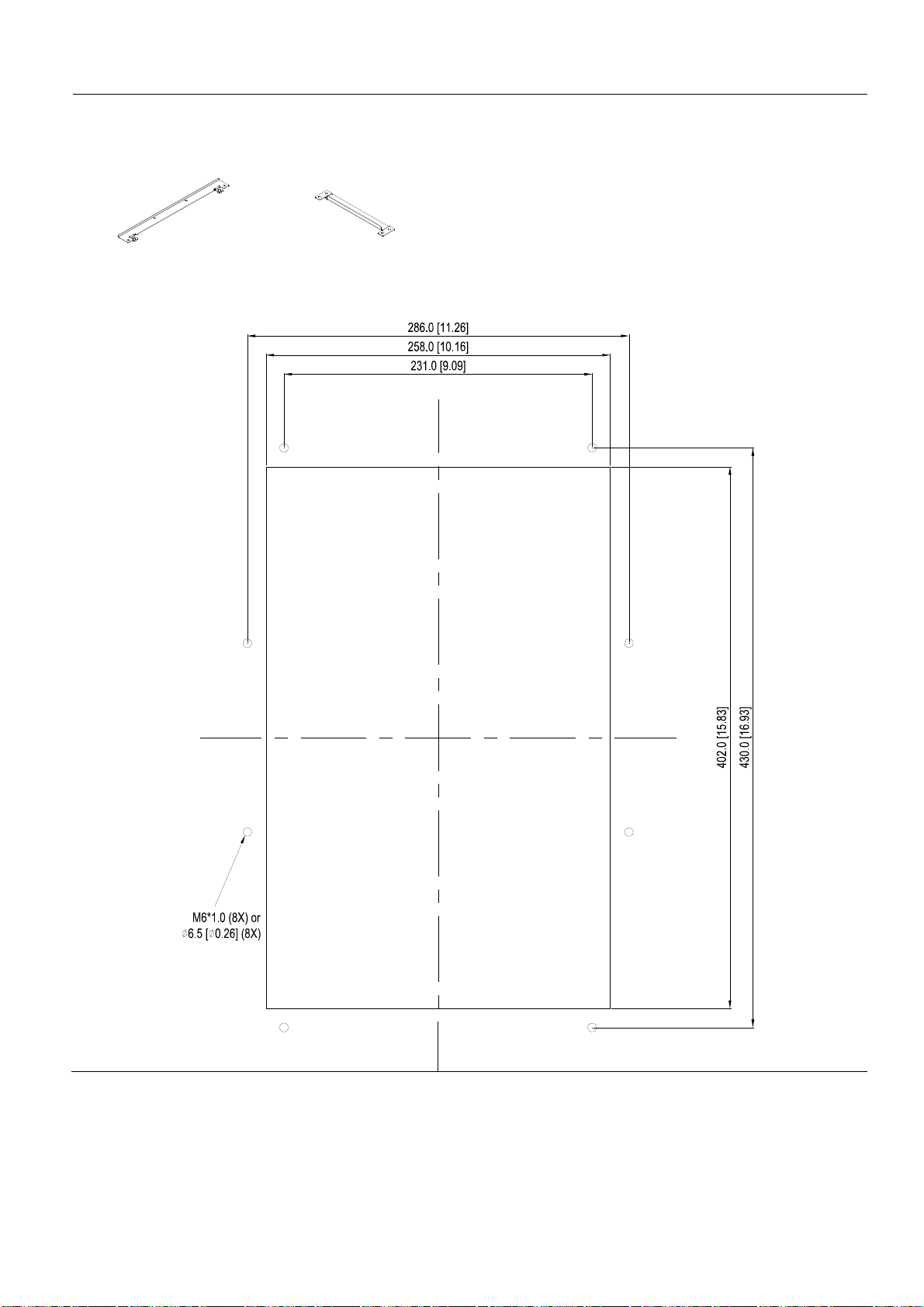
Frame C
『MKC-CFM』
Applicable model
VFD150C23A; VFD185C23A; VFD220C23A; VFD185C43A/43E; VFD220C43A/43E; VFD300C43A/43E
Screw 1*4 ~ M8*P 1.25;
Screw 2*8 ~ M6*P 1.0;
Accessories 1*2
Cutout dimension Unit: mm [inch]
Accessories 2*2
NOTE:
Model VFD007C43E; VFD015C43E; VFD022C43E; VFD037C43E; VFD040C43E; VFD055C43E; VFD075C43E; VFD110C43E;
VFD150C43E; VFD185C43E; VFD220C43E; VFD300C43E will be available for ordering soon. Please contact your local
distributor or Delta representative for detailed launch information.
7-36

Installation『MKC-CFM』
1. Install accessory 1& 2 by fastening 4 of the screw 1(M8). Screw torque: 50~55kg-cm (43.4~47.7Ib-in).
(As shown in the following figure)
2. Plate installation, place 8 of the screw 2 (M6) through accessories 1&2 and the plate then fasten the screws.
Screw torque: 25~30kg-cm (5.21~6.94Ib-in). (As shown in the following figure)
7-37
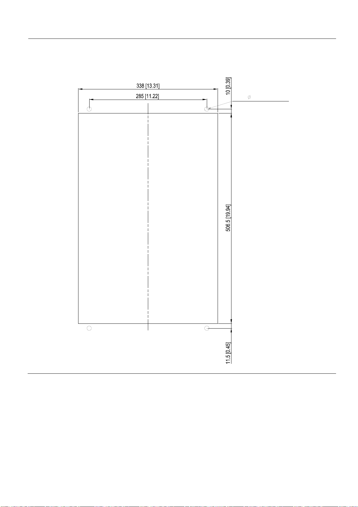
Frame D
Applicable model
VFD300C23A/23E; VFD370C23A/23E; VFD370C43A/43E; VFD450C43A/43E; VFD550C43A/43E; VFD750C43A/43E
Cutout dimension Unit: mm [inch]
M10*P1.5(4X)
OR
11.0[0.43](4X)
7-38

Frame D&E
1. Loosen 8 screws and remove Fixture 2 (as shown in
the following figure).
5. Fasten 4 screws (as shown in the following figure).
Screw torque: 24~26kg-cm (20.8~22.6Ib-in).
2. Loosen 10 screws and remove Fixture 1 (as shown
in the following figure).
3. Fasten 4 screws (as shown in the following figure).
Screw torque: 30~32kg-cm (26.0~27.8Ib-in).
6. Fasten 5 screws (as shown in the following figure).
Screw torque: 24~26kg-cm (20.8~22.6Ib-in).
7. Place 4 screws (M10) through Fixture 1&2 and the
plate then fasten the screws. (as shown in the
following figure)
Screw torque: 200~240kg-cm (173.6~208.3Ib-in).
4. Fasten 5 screws (as shown in the following figure).
Screw torque: 30~32kg-cm (26.0~27.8Ib-in).
7-39

Frame E
Applicable model
VFD450C23A/23E; VFD550C23A/23E; VFD750C23A/23E; VFD900C43A/43E; VFD1100C43A/43E
Cutout dimension Unit: mm [inch]
7-40

Frame F
Applicable model
VFD900C23A/23E; VFD1320C43A/43E; VFD1600C43A/43E
Cutout dimension Unit: mm [inch]
7-41
 Loading...