

Page 1

Delta Economic AC Servo Drive with DMCNET Communication
Delta Economic AC Servo
Drive with DMCNET
ASDA-B2-F
Communication
ASDA-B2-F
Series User Manual
Series User Manual
Page 2

Preface
Thank you for purchasing ASDA-B2-F. This user manual provides related information of ASDA-B2-F series
servo drive and ECMA series servo motors.
This manual includes:
Installation and inspection of the servo drive and servo motor
Configuration of the servo drive
Procedures of trial run
Control functions and adjustment methods of the servo drive
Parameter settings
Communication protocol
Maintenance and inspection
Troubleshooting
Features
B2-F is a cost-effective servo drive for application which requires multi-axis motion control an d can
be operated via DMCNET high-speed network. Besides high response, B2-F also supports
absolute functions and multi-axis operation.
How to use this manual
Users can refer to this user manual during installation, setting, operation and maintenance. Before
tuning and setting, please read through Chapter 1 to 5. This user manual provides specific table of
contents and index for searching. If the requiring information is not available in the table of
contents, please refer to the index.
Technical Supports
If you have any question, please contact local distributors or Delta’s service center.
September, 2015
Page 3

(This page is intentionally left blank.)
September, 2015
Page 4

Table of Contents
Before Operation
Inspection and Model Explanation
1.1 Inspection ·································································································· 1-2
1.2 Product Model ···························································································· 1-3
1.2.1 Nameplate Information ·········································································· 1-3
1.2.2 Model Explanation ··············································································· 1-4
1.3 Servo Drive and Corresponding Servo Motor ···················································· 1-6
1.4 Each Part of the Servo Drive ········································································· 1-7
Installation
2.1 Notes ······································································································· 2-2
2.2 Ambient Conditions of Storage ······································································· 2-2
2.3 Ambient Conditions of Installation ··································································· 2-2
2.4 Installation Direction and Space ····································································· 2-3
2.5 Specification of Circuit Breaker and Fuse ························································· 2-5
2.6 EMI Filter Selection ····················································································· 2-5
2.7 Selection of Regenerative Resistor ································································· 2-7
Wiring
3.1 Connections ······························································································ 3-2
3.1.1 Connecting to Peripheral Devices ··························································· 3-2
3.1.2 Connectors and Terminals of Servo Drive ·················································· 3-3
3.1.3 Wiring Method ····················································································· 3-4
3.1.4 Specification of Motor Power Cable ·························································· 3-5
3.1.5 Specification of Encoder Cable Connector ················································· 3-7
3.1.6 Selection of Wiring Rod ········································································· 3-10
3.2 Basic Wiring ······························································································· 3-11
3.2.1 200 W or models below (without built-in regenerative resistor nor fan) ············· 3-11
3.2.2 400 W ~ 750 W models (with built-in regenerative resistor but no fan) ·············· 3-12
3.2.3 1 kW ~ 1.5 kW models (with built-in regenerative resistor and fan) ·················· 3-13
3.2.4 2 kW ~ 3 kW models (with built-in regenerative resistor and fan) ····················· 3-14
3.3 I / O Signal (CN1) Connection ········································································· 3-15
September, 2015 I
Page 5

3.3.1 I / O Signal (CN1) Connector Terminal Layout ············································· 3-15
3.3.2 Signals Explanation of Connector CN1 ······················································ 3-16
3.3.3 Wiring Diagrams (CN1) ·········································································· 3-18
3.3.4 DI and DO Signal Specified by Users ························································ 3-20
3.4 CN2 Connector ························································································· 3-21
3.5 Wiring of CN3 Connector ············································································· 3-23
3.6 CN6 Connector (DMCNET) ········································································ 3-24
3.7 Standard Connection Example······································································ 3-26
Panel Display and Operation
4.1 Panel Description ························································································ 4-2
4.2 Parameter Setting Procedure ········································································· 4-3
4.3 Status Display ···························································································· 4-6
4.3.1 Save Setting Display ············································································· 4-6
4.3.2 Decimal Point ······················································································ 4-6
4.3.3 Alarm Message ···················································································· 4-6
4.3.4 Positive and Negative Sign Setting ··························································· 4-7
4.3.5 Monitor Display ···················································································· 4-7
4.4 General Function ························································································ 4-10
4.4.1 Operation of Fault Record Display ··························································· 4-10
4.4.2 JOG Mode ·························································································· 4-11
4.4.3 Force DO Output ·················································································· 4-12
4.4.4 Digital Input Diagnosis Operation ····························································· 4-13
4.4.5 Digital Output Diagnosis Operation ·························································· 4-14
Tuning
Trial Operation and Tuning
5.1 Inspection without Load ················································································ 5-2
5.2 Apply Power to the Servo Drive ······································································ 5-3
5.3 JOG Trial Run without Load ··········································································· 5-7
5.4 Trial Run without Load (Speed Mode) ······························································ 5-8
5.5 Tuning Procedure ························································································ 5-10
5.5.1 Flowchart of Tuning Procedure ································································ 5-11
5.5.2 Inertia Estimation Flowchart (with Mechanism) ··········································· 5-12
5.5.3 Flowchart of Auto T unin g ······································································· 5-13
5.5.4 Flowchart of Semi-Auto Tuning································································ 5-14
5.5.5 Limit of Inertia Ratio ·············································································· 5-15
5.5.6 Mechanical Resonance Suppression Method ············································· 5-17
II September, 2015
Page 6

5.5.7 Tuning Mode and Parameters ································································· 5-18
5.5.8 Tuning in Manual Mode ········································································· 5-19
Control Mode of Operation
6.1 Selection of Operation Mode ········································································ 6-2
6.2 Position Mode ··························································································· 6-3
6.2.1 Control Structure of Position Mode ·························································· 6-3
6.2.2 S-curve Filter (Position) ········································································ 6-4
6.2.3 Electronic Gear Ratio ··········································································· 6-5
6.2.4 Low-pass Filter ··················································································· 6-6
6.2.5 Gain Adjustment of Position Loop ··························································· 6-6
6.2.6 Low-frequency Vibration Suppression in Position Mode ······························· 6-7
6.3 Speed Mode ····························································································· 6-10
6.3.1 Selection of Speed Command ································································ 6-10
6.3.2 Control Structure of Speed Mode ···························································· 6-11
6.3.3 Smooth Speed Command ····································································· 6-12
6.3.4 Timing Diagram of Speed Mode ····························································· 6-13
6.3.5 Gain Adjustment of Speed Loop ····························································· 6-14
6.3.6 Resonance Suppression ······································································· 6-18
6.4 Torque Mode ····························································································· 6-23
6.4.1 Selection of Torque Command ······························································· 6-23
6.4.2 Control Structure of Torque Mode ··························································· 6-24
6.4.3 Smooth Torque Command····································································· 6-25
6.4.4 Timing Diagram of Torque Mode ····························································· 6-25
6.5 The Use of Brake ······················································································· 6-26
Parameter Setting
Parameters
7.1 Parameter Definition ··················································································· 7-2
7.2 List of Parameters ······················································································ 7-3
7.3 Parameter Description ················································································· 7-10
P0-xx Monitor Parameters ······································································ 7-10
P1-xx Basic Parameters ········································································· 7-22
P2-xx Extension Parameters ··································································· 7-37
P3-xx Communication Parameters ··························································· 7-50
P4-xx Diagnosis Parameters ··································································· 7-55
P5-xx Motion Setting Parameters ····························································· 7-59
September, 2015 III
Page 7

Table 7.1 Function Description of Digital Input (DI) ········································· 7-63
Table 7.2 Function Description of Digital Output (DO) ····································· 7-65
Communications
8.1 RS-232 Communication Hardware Interface ···················································· 8-2
8.2 RS-232 Communication Parameters Setting ···················································· 8-3
8.3 MODBUS Communication Protocol ································································ 8-4
8.4 Setting and Accessing Communication Parameters ··········································· 8-15
Troubleshooting
Troubleshooting
9.1 Alarm of Servo Drive ··················································································· 9-2
9.2 Alarm of DMCNET Communication ································································ 9-3
9.3 Alarm of Motion Control ··············································································· 9-4
9.4 Causes and Corrective Actions ····································································· 9-5
Absolute System
10.1 Absolute Type of Battery Box and Wiring Rods ················································· 10-3
10.1.1 Specifications ··················································································· 10-3
10.1.2 Battery Box Dimensions ..................................................................................... 10-5
10.1.3 Connection Cable for Absolute Encoder ............................................................ 10-6
10.1.4 Battery Box Cable ............................................................................................... 10-8
10.2 Installation ································································································ 10-9
10.2.1 Install Battery Box in Servo System ................................................................... 10-9
10.2.2 How to Install the Battery .................................................................................... 10-13
10.2.3 How to Replace a Battery ................................................................................... 10-14
10.3 Parameters Related to Absolute Servo System ················································· 10-16
10.4 Servo Drive Alarm List for Absolute Function and Monitoring Variables ·················· 10-17
10.5 System Initialization and Operation Procedures ················································ 10-18
10.5.1 System Initialization ............................................................................................ 10-18
10.5.2 Pulse Number ..................................................................................................... 10-19
10.5.3 PUU Number ...................................................................................................... 10-20
10.5.4 To Initialize the Absolute Coordinate via Parameters ......................................... 10-21
10.5.5 Use Communication to Access Absolute Position .............................................. 10-21
IV September, 2015
Page 8

Appendix
Specifications
Specifications of ASDA-B2-F Se
Specifications of Servo Motors (ECMA Series) ···························································· A-4
Torque Features (T-N Curves) ·················································································· A-13
Overload Features ································································································· A-15
Dimensions of Servo Drive ······················································································ A-17
Dimensions of Servo Motor ······················································································ A-21
rvo Drive ··································································· A-2
Accessories
Power Conne
Power Cable ······································································································· B-3
Encoder Connector ································································································ B-5
Encoder Cable ······································································································ B-5
Encoder Cable (Absolute Type) ················································································ B-6
Battery Box Cable AW ··························································································· B-7
Battery Box Cable IW ···························································································· B-7
ctor ··································································································· B-2
Battery Box (Absolute Type) ··················································································· B-8
I/O Connector Terminal ··························································································· B-9
CN1 Convenient Connector ····················································································· B-9
PC Connection Cable ····························································································· B-10
Terminal Block Module ···························································································· B-10
Optional Accessories ······························································································ B-11
Maintenance and Inspection
Basic Inspect
Maintenance ········································································································· C-3
The Lifetime of Machinery Parts ················································································ C-3
ion ···································································································· C-2
September, 2015 V
Page 9

(This page is intentionally left blank.)
VI September, 2015
Page 10

Inspection and Model
Explanation
Before using ASDA-B2-F, please pay attention to the description about the inspection,
nameplate, and model type. Suitable motor model for your servo drive can be found in
the table of Chapter 1.3.
111111111111111111111111111111111111111 11111
1.1 Inspection ........................................................................................................ 1-2
1.2 Product Model ··············································································· 1-3
1.2.1 Nameplate Information ································································ 1-3
1.2.2 Model Explanation ······································································ 1-4
1.3 Servo Drive and Corresponding Servo Motor ········································ 1-6
1.4 Each Part of the Servo Drive ····························································· 1-7
September, 2015 1-1
Page 11

Inspection and Model Explanation ASDA-B2-F
1.1 Inspection
In order to prevent the negligence during purchasing and delivery, please inspect the following
items carefully.
Item Description
1
Please check if the product
is what you have
purchased.
Check the part number of the motor and the servo drive on the nameplate.
Refer to the next page for the model explanation.
Check if the motor shaft
can rotate smoothly.
Check if there is any
damage shown on its
appearance.
Check if there is any loose
screw.
If any of the above situations happens, please contact the distributors to solve the problems.
A complete and workable servo set should include:
(1) One servo drive and one servo motor.
(2) One UVW motor power cable, the U, V and W wires can connect to the socket attached by
the servo drive and another side is the plug which could connect to the socket of the motor.
And a green ground wire which should be connected to the ground terminal of the servo
drive. (selective purchase)
(3) An encoder cable which connects to the socket of the encoder. One side of it connects to
CN2 servo drive and another side is the plug. (selective purchase)
(4) 15-PIN connector which is used in CN1 (selective purchase)
(5) 9-PIN connector which is used in CN2. (selective purchase)
(6) 6-PIN connector which is used in CN3. (selective purchase)
Rotate the motor shaft by hand. If it can be rotated smoothly, it means the
motor shaft is normal. However, it cannot be rotated by hand if the motor
has an electromagnetic brake.
Visually check if there is any damage or scrape of the appearance.
Make sure no screw is un-tightened or fall off.
(7) RJ-45 connector which is used in CN6.
1-2 September, 2015
Page 12
ASDA-B2-F Inspection and Model Explanation
1.2 Product Model
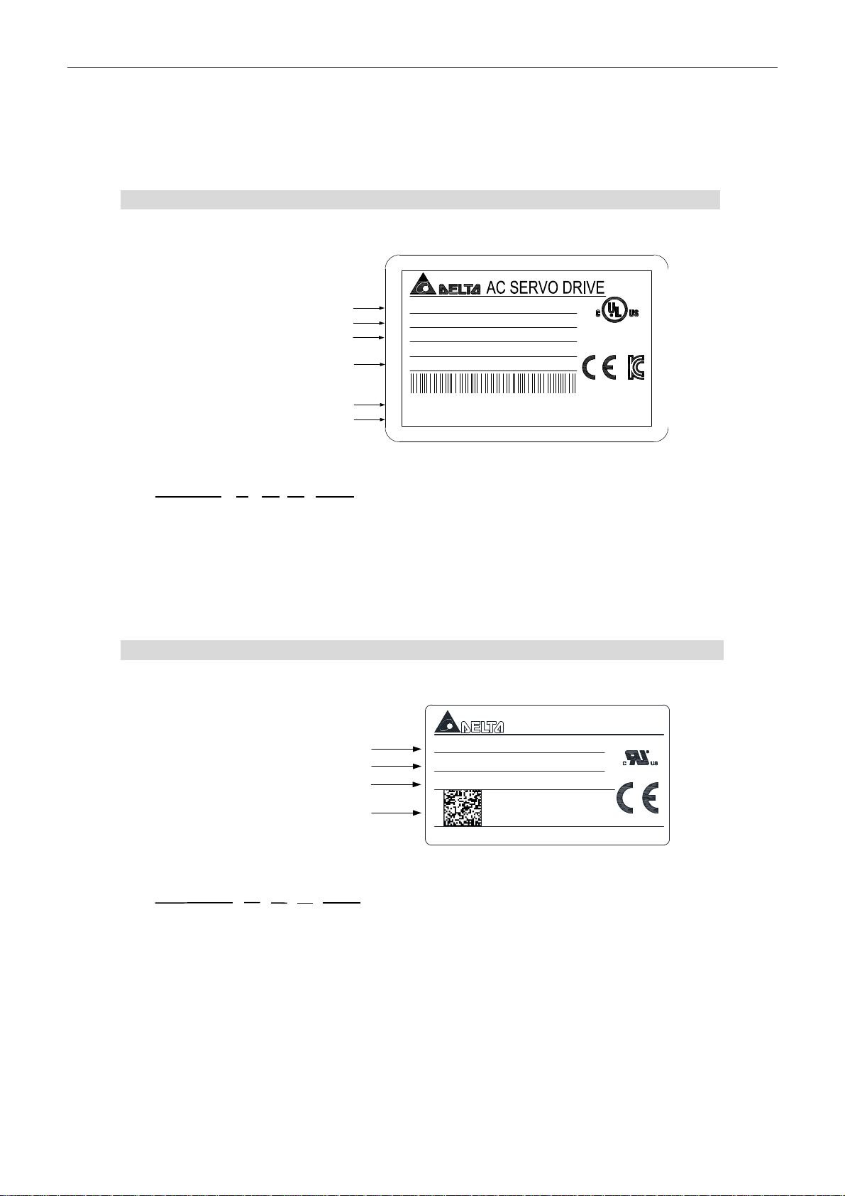
1.2.1 Nameplate Information
ASDA-B2-F Series Servo Drive 0
Nameplate Information
Model Name
Capacity Specificat ion
Applicable Power Supply
Rated Current Output
Barcode
Firmwa re V ersion
Serial Number
B21521F W 14 17 0001
MODEL : ASD-B2-1521-F
POWER : 1.5kW
INPUT : 200~230V 3PH 50/60Hz 5.9A
200~230V 1PH 50/60Hz 10.3A
OUTPUT : 110V 0~250Hz 8.3A
B21521FW14170001
01.74
DELTA ELECTRONICS, INC.
LISTED
19XK
IND. CONT. E Q.
MADE IN TAIWAN
Model Name
Production Factory (T: Taoyuan; W: Wujiang)
Year of Production (3: year 2013 or 14: year 2014)
Week of Production (from 1to 52)
Serial Number
(Production sequence of a week, starting from 0001)
1
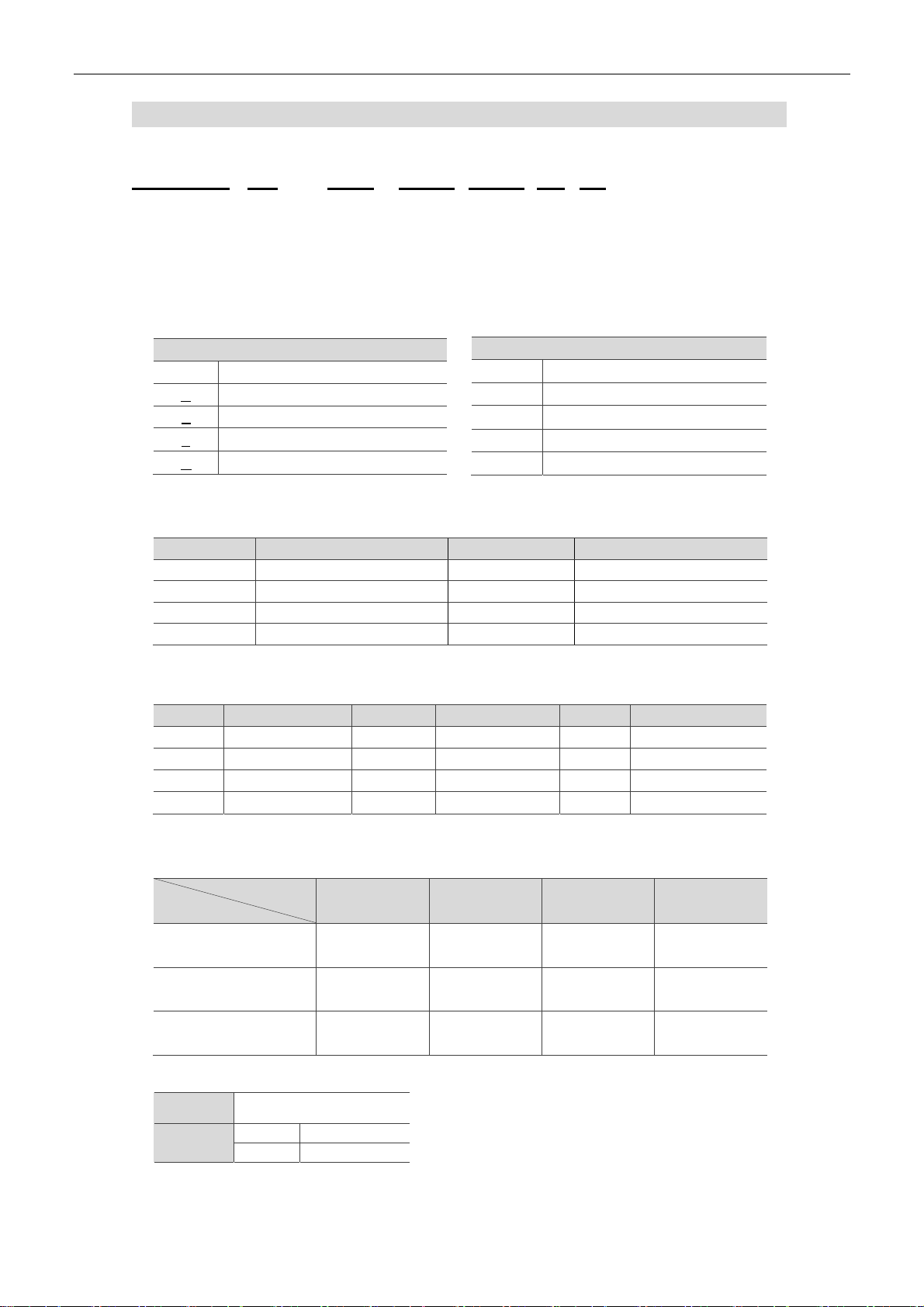
ECMA Series Servo Motor 0
Nameplate Information
AC SER VO MOTOR
Model Name
Input Power
Rated Speed and Rated Output
Barcode
Serial Number
C10602ES T 14 33 0001
Model Name
Production Factory (T: Taoyuan; W: Wujiang)
Year of Production (14: year 2014)
Week of Production (from 1 to 52)
Serial Number
(Production sequence of a week, starting from 0001)
MODEL: ECMA-C10602ES
INPUT: VAC 110 A 1.55 Ins. A
OUTPUT: r/min 3000 N.m 0.64 kW 0.2
C10602EST14330001
Delta Electronics, Inc. MADE IN XXXXXX
September, 2015 1-3
Page 13

Inspection and Model Explanation ASDA-B2-F
1.2.2 Model Explanation
ASDA-B2-F Series Servo Drive 0
1
ASD-B2-0421- F
Product Name
AC Servo Drive
Series
B2
Rate Output Power
Input Voltage and Phase
Model Type
Code Spec. Code Spec.
01 100 W 10 1 kW
02 200 W 15 1.5 kW
04 400 W 20 2 kW
07 750 W 30 3 kW
Code Voltage / Phase
21 220V 1 phase
23 220V 3 phase
Type
F × × × ○ × ×
Full-Closed
Control
EtherCAT CANopen DMCNET E-CAM
Extension Port for
Digital Input
1-4 September, 2015
Page 14
ASDA-B2-F Inspection and Model Explanation
ECMA Series Servo Motor 0
ECMA-C10602ES
Product Name ECM: Electronic Commutation Motor
Motor Type A: AC Servo Motor
Name of the Series
Rated Voltage and Rated Speed
Code Spec.
C 220 V / 3,000 rpm
E 220 V / 2,000 rpm
F 220 V / 1,500 rpm
G 220 V / 1,000 rpm
Code Spec.
1 Incremental type, 20-bit
2 Incremental type, 17-bit
3 2500 ppr
M Magnet type, 13-bit
Motor Frame Size
code Spec. code Spec.
04 40 mm 10 100 mm
06 60 mm 13 130 mm
08 80 mm 18 180 mm
09 86 mm - -
Rated Power Output
1
Encoder Type
code Spec. code Spec. code Spec.
01 100 W 05 500 W 10 1.0 kW
02 200 W 06 600 W 15 1.5 kW
03 300 W 07 700 W 20 2.0 kW
04 400 W 09 900 W 30 3.0 kW
Type of Shaft Diameter and Oil Seal
Round Shaft
(with fixed screw holes)
Keyway E F - -
Keyway
(with fixed screw holes)
w/o Brake,
w/o Oil Seal
Shaft Diameter
Standard S
Specific
3 42 mm
7 14 mm
- - C D
P Q R S
with Brake, w/o
Oil Seal
w/o Brake, with
Oil Seal
With Brake,
with Oil Seal
September, 2015 1-5
Page 15

Inspection and Model Explanation ASDA-B2-F
M
di
hi
h
1.3 Servo Drive and Corresponding Servo Motor
Motor Servo Drive
1
Motor
series
Low Inertia
Medium Inertia
g
um-
inertia
e
High Inertia
Power
Single/Three-
phase
ECMA-C 3000 r/min
Single/Three-
phase
ECMA-E 2000 r/min
Single/Three-
phase
ECMA-F
1500 r/min
Single/Three-
r/min
phase
ECMA-C/G 3000
Output
(W)
50
100
200
400
400
750
750
1000
1000
2000
3000
500
1000
1500
2000
2000
3000
850
1300
3000
400
750
300
600
900
Model Number
ECMA-C1040F□S 0.69 2.05
ECMA-C0401□S
ECMA-C0602□S
ECMA-C0604□S
ECMA-C0804□7
ECMA-C0807□S
ECMA-C0907□S
ECMA-C0910□S
ECMA-C1010□S
ECMA-C1020□S
ECMA-C1330□4
ECMA-E1305□S
ECMA-E1310□S
ECMA-E1315□S
ECMA-E1320□S
ECMA-E1820□S
ECMA-E1830□S
ECMA-F1308□S
ECMA-F1313□S
ECMA-F1830□S
ECMA-C0604□H
ECMA-C0807□H
ECMA-G1303□S
ECMA-G1306□S
ECMA-G1309□S
Rated
Current
(Arms)
0.90 2.70
1.55 4.65
2.60 7.80
2.60 7.80
5.10 15.30
3.66 11.00
4.25 12.37
7.30 21.90
12.05 36.15
17.2 47.5
2.90 8.70
5.60 16.80
8.30 24.90
11.01 33.03
11.22 33.66
16.10 48.30
7.10 19.40
12.60 38.60
19.40 58.20
2.60 7.80
5.10 15.30
2.50 7.50
4.80 14.40
7.50 22.50
Max.
Instantaneous
current
(A)
Continuous
Model Number
ASD-B2-0121-F 0.90 2.70
ASD-B2-0221-F 1.55 4.65
ASD-B2-0421-F 2.60 7.80
ASD-B2-0721-F 5.10 15.30
ASD-B2-1021-F 7.30 21.90
ASD-B2-2023-F 13.40 40.20
ASD-B2-3023-F 19.40 58.20
ASD-B2-0421-F 2.60 7.80
ASD-B2-1021-F 7.30 21.90
ASD-B2-1521-F 8.30 24.90
ASD-B2-2023-F 13.40 40.20
ASD-B2-3023-F 19.40 58.20
ASD-B2-1021-F 7.30 21.90
ASD-B2-2023-F 13.40 40.20
ASD-B2-3023-F 19.40 58.20
ASD-B2-0421-F 2.60 7.80
ASD-B2-0721-F 5.10 15.30
ASD-B2-0421-F 2.60 7.80
ASD-B2-0721-F 5.10 15.30
ASD-B2-1021-F 7.30 21.90
Output
Current
(Arms)
Max.
Instantaneous
output
current
(A)
Note:
1. () at the ends of the servo drive model names are for optional configurations.
For the actual model name, please refer to the ordering information of the actual purchased product.
2. () in the model names are for encoder resolution types. = 1: Incremental type, 20-bit;
= 2: Incremental type, 17-bit; = 3: 2500 ppr; = M: Magnet type. The listed motor model name is
for information searching, please contact to your local distributors for actual purchased product.
3. () in the model names represents brake or keyway oil seal.
The above table shows the specification of servo drive which has triple rated current. For detailed
specification of the servo motor and servo drive, please refer to Appendix A.
1-6 September, 2015
Page 16
ASDA-B2-F Inspection and Model Explanation
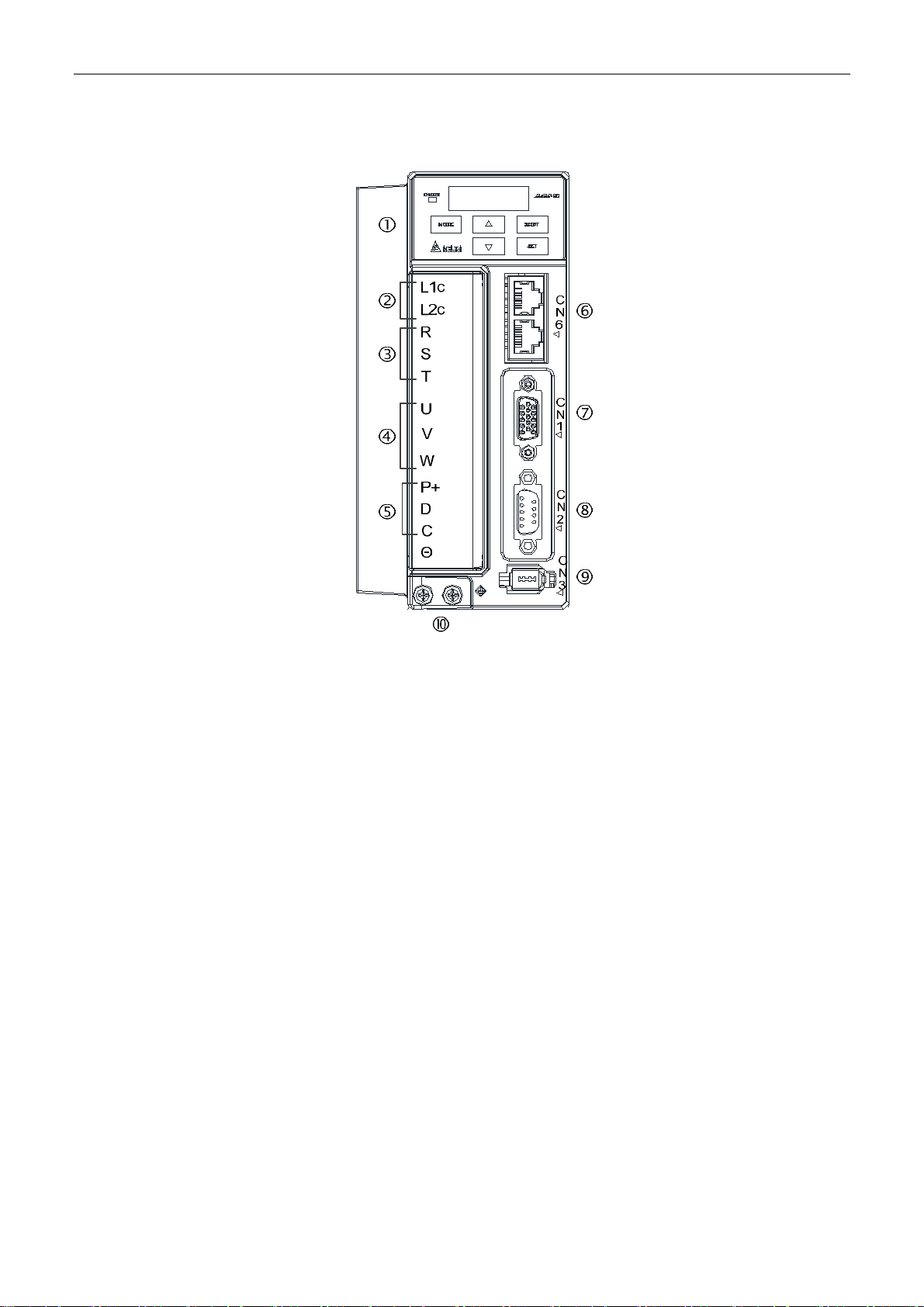
1.4 Each Part of the Servo Drive
1
Heat sink:
Used to secure servo drive and for heat dissipation.
Control Circuit Terminal (L1c、L2c):
Used to connect 200 ~ 230 V
Ac, 50 / 60 Hz 1-phase / 3-phase VAC supply.
Main Circuit Terminal (R, S, T):
Used to connect 200 ~ 230 V, 50 / 60 Hz commercial power supply.
Servo Motor Output (U, V, W):
Used to connect servo motor. Never connect the output terminal to main circuit power.
The AC servo drive may be destroyed beyond repair if incorrect cables are connected to the
output terminals.
Regenerative Resistor:
(1) When using an external regenerative resistor, connect P⊕ and C to the regenerative
resistor and ensure that the circuit between P⊕ and C is open.
(2) When using the internal regenerative resistor, ensure that the circuit between P⊕ and D
is closed and the circuit between P⊕ and C is open
CN6: DMCNET Connector: Communication port for DMCNET communi cation.
CN1: I/O Interface: Used to connect external controller (PLC) or control I/O signal.
CN2: Encoder Interface: Used to connect encoder of servo motor.
CN3: Serial Communication Interface: It is controlled by MODBUS and supports RS-232.
It can be connected to controllers.
Ground Terminal: Used to connect grounding wire of power supply and servo motor.
Please connect it properly to avoid electric shock.
September, 2015 1-7
Page 17

Inspection and Model Explanation ASDA-B2-F
(This page is intentionally left blank.)
1
1-8 September, 2015
Page 18

Installation
This chapter allows you to properly install the device. Please follow the instruction
mentioned in this chapter during installation. Information about specification of circuit
breaker, fuse, EMI filter selection, and selection of regenerative resistor are also
included.
11111111111111111111111111111111111111111111 1111111
2.1 Notes ······························································································ 2-2
2.2 Ambient Conditions of Storage ····························································· 2-2
2.3 Ambient Conditions of Installation ························································· 2-2
2.4 Installation Direction and Space ···························································· 2-3
2.5 Specification of Circuit Breaker and Fuse ················································ 2-5
2.6 EMI Filter Selection ············································································ 2-5
2.7 Selection of Regenerative Resistor ························································ 2-7
September, 2015 2-1
Page 19

Installation ASDA-B2-F
2.1 Notes
Please pay special attention to the following:
Do not strain the cable connection between the servo drive and the servo motor.
2
Make sure each screw is tightened when fixing the servo drive.
The motor shaft and the ball screw should be parallel.
If the connection between the servo drive and the servo motor is over 20 meters, please
thicken the connecting wire, UVW as well as the encoder cable.
Tighten the four screws that fix the motor.
2.2 Ambient Conditions of Storage
Before the installation, this product has to be kept in the shipping carton. In order to retain the
warranty coverage and for the maintenance, please follow the instructions below when storage, if
the product is not in use temporally:
Store the product in a dry and dust-free location.
Store the product within an ambient temperature range of -20°C to +65°C.
S t ore the product within a relative humidity range of 0% to 90% and a non-condensing
environment.
Avoid storing the product in the environment of corrosive gas and liquid.
It is better to store the product in the shipping carton and put it on the shelf or working
platform.
2.3 Ambient Conditions of Installation
The most appropriate temperature of this servo drive is between 0°C and 55°C. If it is over
45°C, please place the product in a well-ventilated environment so as to ensure it s pe rform an ce.
If the product is installed in an electric box, make sure the size of the electric box and its
ventilation condition will not overheat and endanger the internal electronic device. Also, pay
attention to the vibration of the machine. Check if the vibration will influence the electro nic device
of the electric box. Besides, the ambient conditions should be:
No over-heat device.
No water drop, vapor, dust or oily dust.
No corrosive and inflammable gas or liquid.
No airborne dust or metal particles.
With solid foundation and no vibration.
No interference of electromagnetic noise.
2-2 September, 2015
Page 20
ASDA-B2-F Installation
The ambient temperature of the motor is between 0°C and 40°C and the ambient conditions should be:
No over-heat device.
No water drop, vapor, dust or oily dust.
No corrosive and inflammable gas or liquid.
No airborne dust or metal particles.
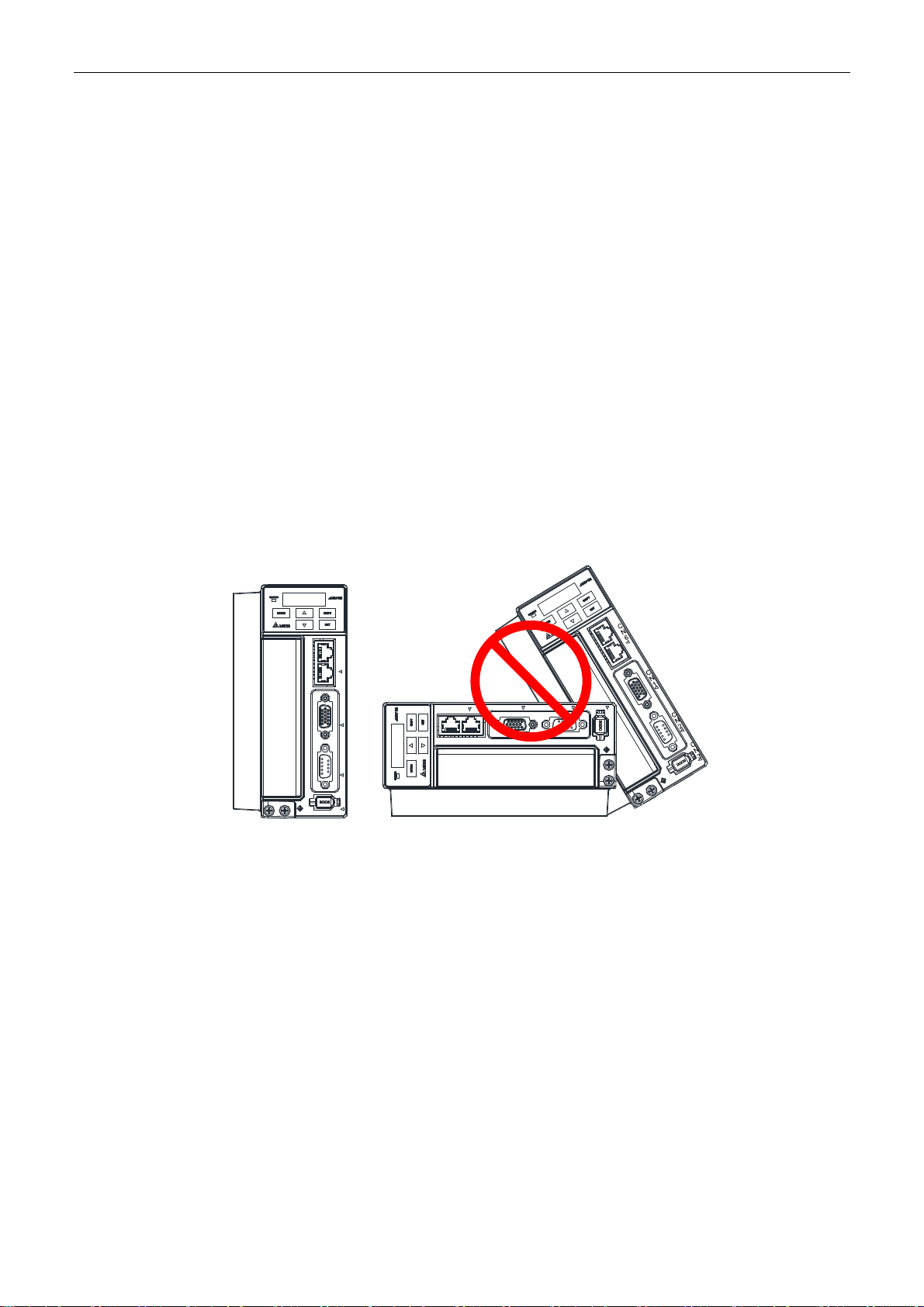
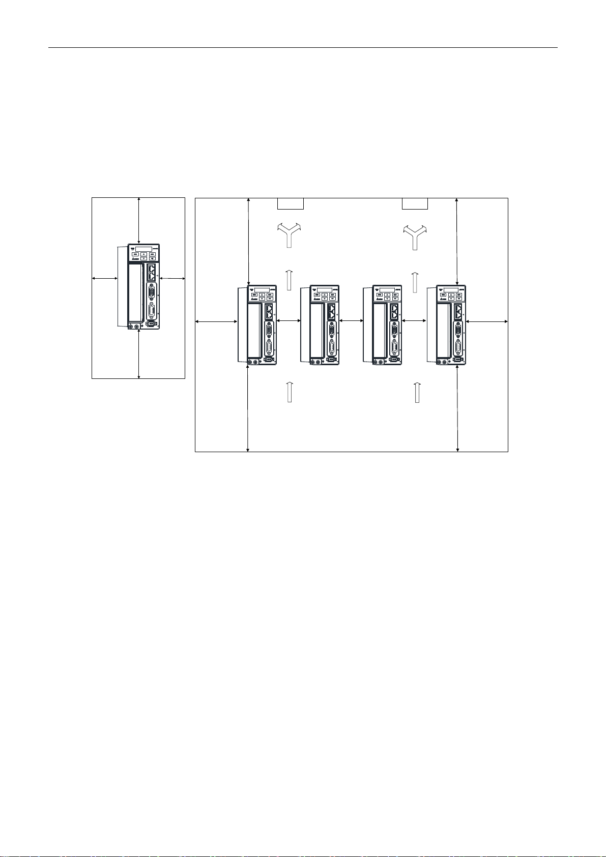
2.4 Installation Direction and Space
Notes:
Incorrect installation may result in a drive malfunction or premature failure of the drive and
or motor.
In order to ensure the drive can be well-cooled and the environment is well circulated,
sufficient space between adjacent object and the baffle is needed.
Ensure all ventilation holes are not obstructed. Do not install the drive in a horizontal
direction or malfunction and damage will occur.
C
N
6
2
CN3
C
N
1
C
N
2
C
N
3
CN6
CN1
CN2
Correct Incorrect
Installing servo drives:
ASDA-B2-F series servo drive should be mounted perpendicular to a dry and solid surface that
conforms to NEMA standards. To ensure a well-ventilated environment, sufficient space between
adjacent object and the baffle is required. 50 mm (approx. 2 inch.) of clearance is suggested. If
wiring is needed, please leave the space for it. Please note that the rack or the surface shall
conduct heat well, so as to avoid the overheating of servo drive.
September, 2015 2-3
Page 21
Installation ASDA-B2-F
Installing motors:
ECMA series motors shall be mounted to the mounting surface which is dry and stable. Please
make sure the environment is well-ventilated and the motor is properly grounded.
For the dimensions and specifications of the servo drive and servo motor, please refer to
2
Appendix A -Specifications.
Mounting distances and ventilation:
20 mm
(0.8 inches)
min.
50 mm
(2.0 inches) min.
C
N
6
20 mm
C
(0.8 inches)
N
1
C
N
2
C
N
3
50 mm
(2.0 inches) min.
min.
40 mm
(1.6 inches)
min.
(4.0 inches)
100 mm
(4.0 inches)
min.
100 mm
min.
FAN FAN
Air Flow
C
N
6
C
N
10 mm
1
(0.4
inches)
C
N
min.
2
C
N
3
C
N
6
C
N
1
C
N
2
C
N
3
10 mm
(0.4
inches)
min.
Air Flow
C
N
6
C
N
10 mm
1
(0.4
inches)
C
N
min.
2
C
N
3
100 mm
(4.0 inches)
min.
C
N
6
C
N
40 mm
1
(1.6 inches)
C
N
2
C
N
3
100 mm
(4.0 inches)
min.
min.
To lower the air resistance and ensure the drive is well ventilated, please follow the instructions
during installation and leaving sufficient space as suggested.
Note:
The above diagrams are not in equal proportion. Please refer to the annotation
2-4 September, 2015
Page 22

ASDA-B2-F Installation
2.5 Specification of Circuit Breaker and Fuse
Caution: Please use the fuse and circuit breaker that is recognized by UL/CSA.
Servo Drive Model Circuit Breaker Fuse (Class T)
Operation Mode General General
ASD-B2-0121-F 5A 5A
ASD-B2-0221-F 5A 6A
ASD-B2-0421-F 10A 10A
ASD-B2-0721-F 10A 20A
ASD-B2-1021-F 15A 25A
ASD-B2-1521-F 20A 40A
ASD-B2-2023-F 30A 50A
ASD-B2-3023-F 30A 70A
Note:
If the servo drive equips with earth leakage circuit breaker for avoiding electric leakage, please choose the
current sensitivity which is over 200 mA and can continue up to 0.1 seconds.
2.6 EMI Filter Selection
2
Item Power Servo Drive Model
1 100 W ASD-B2-0121-F RF007S21AA RF022M43AA N
2 200 W ASD-B2-0221-F RF007S21AA RF022M43AA N
3 400 W ASD-B2-0421-F RF007S21AA RF022M43AA N
4 750 W ASD-B2-0721-F RF007S21AA RF022M43AA N
5 1000 W ASD-B2-1021-F RF015B21AA RF075M43BA N
6 1500 W ASD-B2-1521-F RF015B21AA RF075M43BA N
7 2000 W ASD-B2-2023-F - RF037B43BA N
8 3000 W ASD-B2-3023-F - RF037B43BA N
Recommended EMI Filter
1PH 3PH
Foot Print
EMI Filter Installation
All electronic equipment (including servo drive) generates high or low frequency noise during
operation and interfere the peripheral equipment via conduction or radiation. With EMI Filter and
the correct installation, much interference can be eliminated. It is suggested to use Delta’s EMI
Filter to suppress the interference better.
When installing servo drive and EMI Filter, please follow the instructions of the user manual and
make sure it meets the following specifications.
1. EN61000-6-4 (2001)
2. EN61800-3 (2004) PDS of category C2
3. EN55011+A2 (2007) Class A Group 1
September, 2015 2-5
Page 23
2
Installation ASDA-B2-F
General Precaution
In order to ensure the best performance of EMI Filter, apart from the instructions of servo drive
installation and wiring, please follow the precautions mentione d below:
1. The servo drive and EMI Filter should be installed on the same metal plate.
2. When installing servo drive and EMI Filter, the servo drive should be install ed above the EMI
Filter.
3. The wiring should be as short as possible.
4. The metal plate should be well grounded.
5. The servo drive and the metal cover of EMI Filter or grounding should be firmly fixed on the
metal plate. Also, the contact area should be as large as possible.
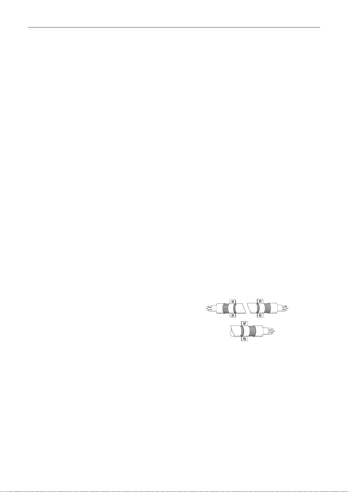
Motor Cable Selection and Installation Precautions
The selection of motor cables and installation affect the performance of EMI Filter. Please follow
the precautions mentioned below.
1. Use the cable that has braided shielding (The effect of double shielding is better)
2. The shield on both sides of the motor cable should be grounded in the shortest distan ce and
the largest contact area.
3. The protective paint of the U-shape saddle and metal plate should be removed in order to
ensure the good contact. Please see Fig. 1.
4. It should have correct connection between the braided shielding of the motor cable and the
metal plate. The braided shielding on both sides of the motor cable should be fixed by the
U-shape saddle and metal plate. Please see Fig. 2 for the correct connection.
Fig.1 Fig. 2
2-6 September, 2015
Page 24

ASDA-B2-F Installation
2.7 Selection of Regenerative Resistor
When the direction of pull-out torque is different from the rotation, it means the electricity is sent
back to the servo drive from the load-end. It becomes the capacitance of DC Bus and increases
the voltage. When the voltage increases to a specific value, the come-back eletricity can only be
consumed by regenerative resistor. There is a built-in regenerative resistor in the servo drive.
Users can also use the external regenerative resistor if needed.
Specification of built-in regenerative resistor provided by ASDA-B2-F Series
Specification of built-in regenerative
Servo Drive
(KW)
0.1 -- -- -- 60
0.2 -- -- -- 60
0.4 100 60 30 60
0.75 100 60 30 60
1.0 40 60 30 30
1.5 40 60 30 30
2.0 20 100 50 15
3.0 20 100 50 15
Resistance
(P1-52) (Ohm)
resistor
Capacity
(P1-53) (Watt)
*1The capacity of
built-in regenerative
resistor (Watt)
Minimum
allowable
resistance (Ohm)
2
*1The capacity of built-in regenerative resistor (average value) is 50% of the rated capacity of the built-in
regenerative resistor. The capacity of the external regenerative resistor is the same as the built-in one.
When the regenerative resistor exceeds the capacity of built-in regenerative resistor, the external
regenerative resistor should be applied. Please pay special attention to the following when using
the regenerative resistor.
1. Please correctly set up the resistance (P1-52) and capacity (P1-53) of regenerative resistor.
Or it might influence the performance of this function.
2. If users desire to use the external regenerative resistor, please make sure the applied value
should not be smaller than the value of built-in regenerative resistor. In general application,
more than one resistor will be serial connected. If the value (from serial connected resistors)
exceeds the setting range, users can reduce the value by parallel connecting the resistor. If
users desire to connect it in parallel to increase the power of regenerative resistor, please
make sure the capacitanc e meets the requirements.
3. In natural environment, if the capacity of regenerative resistor (the average value) is within
the rated capacity, the temperature of the capacitance will increase to 120℃ or even higher
(under the condition of regenerative energy keeps existing). For safety concerns, please
apply the method of forced cooling in order to reduce the temperature of rege nerative resistor.
Or, it is suggested to use the regenerative resistor which is equipped with thermal switches.
Please contact the distributors for load characteristics of the regenerative resistor.
When using the external regenerative resistor, the resistor should connect to P, C terminal and
the contact of P, D terminal should be opened. It is recommended to choose the above
mentioned capacitance. For easy calculation of regenerative resistor capacity, except the energy
consumed by IGBT, two ways are provided to select the capacity of external regenerative
resistor according to the selected linear motor or rotary motor.
September, 2015 2-7
Page 25

2
Installation ASDA-B2-F
(1) Regenerative Power Selection
(a) When the external load on torque does not exist
If the motor operates back and forth, the energy generated by the brake will go into the
capacitance of DC bus. When the voltage of the capacitance exceeds a specific value, the
redundant energy will be consumed by regenerative resistor. Two ways of selecting
regenerative resistor are provided here. The table below provides the energy calculation
method. Users can refer to it and calculate the selected regenerative resistor.
Servo Drive
(kW)
Low Inertia
Medium
Inertia
Medium -
High Inertia
High Inertia
0.1
0.2
0.4
0.75
1.0
2.0
3.0
0.4
1.0
1.5
2.0
3.0
1.0
2.0
3.0
0.4
0.75
1.0
Motor
ECMA-Cᇞ040F□□
ECMA-Cᇞ0401□□
ECMA-Cᇞ0602□□
ECMA-Cᇞ0604□□
ECMA-Cᇞ0804□□
ECMA-Cᇞ0807□□
ECMA-Cᇞ0907□□
ECMA-Cᇞ0910□□
ECMA-Cᇞ1010□□
ECMA-Cᇞ1020□□
ECMA-Cᇞ1330□□
ECMA-Eᇞ1305□□
ECMA-Eᇞ1310□□
ECMA-Eᇞ1315□□
ECMA-Eᇞ1320□□
ECMA-Eᇞ1820□□
ECMA-Eᇞ1830□□
ECMA-Fᇞ1308□□
ECMA-Fᇞ1313□□
ECMA-Fᇞ1830□□
ECMA-Gᇞ1303□□
ECMA-Gᇞ1306□□
ECMA-Gᇞ1309□□
Rotor Inertia
J (× 10-4kg.m2)
0.021 0.10 4.21
0.037 0.18 4.21
0.177 0.87 5.62
0.277 1.37 8.42
0.68 3.36 8.42
1.13 5.59 17.47
1.93 9.54 17.47
2.62 12.96 21.22
2.65 13.1 21.22
4.45 22.0 25.58
12.7 62.80 25.58
8.17 40.40 8.42
8.41 41.59 21.22
11.18 55.29 25.58
14.59 72.15 25.58
34.68 171.49 25.58
54.95 217.73 31.20
13.6 67.25 21.22
20.0 98.90 25.58
54.95 217.73 28
8.17 17.96 8.42
8.41 18.48 17.47
11.18 24.57 21.22
Regenerative power
from empty load
3000r/min to stop Eo
(joule)
The maximum
regenerative power
of capacitance
Ec (joule)
Eo = J * Wr2/182 (joule), Wr: r/min
Assume that the load inertia is N times to the motor inertia and the motor decelerates from 3000
r/min to 0, its regenerative energy is (N+1) x Eo. The consumed regenerative resistor is (N+1) ×
Eo - Ec joule. If the cycle of back and forth operation is T sec, then the power of regenerative
resistor it needs is 2× ((N+1) x Eo - Ec) / T.
Steps Item Calculation and Setting Method
1 Set the capacity of regenerative resistor to the maximum Set P1-53 to the maximum value
2 Set T cycle of back and forth operation Enter by the user
3 Set the rotational speed wr Enter by the user or read via P0-02
4 Set the load/motor inertia ratio N Enter by the user or read vi a P0-02
5 Calculate the maximum regenerative energy Eo Eo= J * wr2/182
6 Set the absorbable regenerative energy Ec Refer to the above table
7 Calculate the needful capacitance of regenerative resistor
2 ×((N+1) × Eo-Ec)/ T
2-8 September, 2015
Page 26

ASDA-B2-F Installation
Take the motor (400 W with frame size 60) as the example, the cycle of back and forth operation
is T = 0.4 sec, the maximum speed is 3000 r/min and the load inertia is 7 times to the motor
inertia. Then, the needful power of regenerative resistor is 2 × ((7+1) × 1.37 – 8) / 0.4 = 14.8 W. If
it is smaller than the built-in capacity of regenerative resistor, the built-in 60W regenerative
resistor will do. Generally speaking, when the need of the external load inertia is not much, the
built-in regenerative is enough. The diagram below describes the actual operation. The smaller
power of the regenerative resistor it is, the more energy it accumulates and the higher
temperature it will be. When the temperature is higher than a specific value, AL005 occurs.
(b) If the external load torque exists, the motor is in reverse rotation.
Usually, the motor is in forward rotation, which means the torque output direction of the
motor is the same as the rotation direction. However, in some applications, the direction of
torque output is different from the rotation. In this situation, the motor is in reverse rotation.
The external energy goes into the servo drive through the motor. The diagram below is one
example. When the external force direction is the same as the moving direction, the servo
system has to use the force of the opposite direction to keep the speed and sta bility. Huge
amount of energy will return to the servo drive at the moment. When DC-BUS is full and
unable to store the regenerative energy, the energy will be leaded to regenerative resistor
and consumed.
Motor Speed
External Load Torque
2
Motor Output Torque
Negative
Torque
Negative torque: TL × Wr TL: external load torque
For safety reasons, please calculate it by considering the safest situation.
For example, when the external load torque is +70% rated torque and the rotation reach es
3000 r/min, then take 400W (the rated torque is 1.27 Nt-m) as the example, users have to
connect the regenerative resistor which is 2 × (0.7× 1.27) × (3000 × 2 × π/60) = 560 W, 60
.
Positive
Torque
Negative Tor que
Positive
Torque
September, 2015 2-9
Page 27
2
(
)
(
)
Installation ASDA-B2-F
(2) Simple Selection
Choose the appropriate regenerative resistor according to the allowable frequency and empty
load frequency in actual operation. The so-called empty allowable frequency is the frequency of
continuous operation when the servo motor runs from 0 r/min to the rated speed and then
decelerates from the rated speed to 0r/min within the shortest time. The following table lists the
allowable frequency when the servo drive runs without load (times/min).
Allowable frequency when the servo drive runs without load (times/min)
and uses a built-in regenerative resistor
Motor Capacity
600 W 750 W 900 W 1.0 kW 1.5 kW 2.0 kW 2.0 kW 3.0 kW
Servo Motor
ECMA□□C
ECMA□□E
ECMA□□G
06 07 09 10 15 20 20 30
- 312 - 137 - 83 (F100) -
- - - 42 32
42 - 31 - - - - -
24
(F130)
10
(F180)
11
When the servo motor runs with load, the allowable frequency will be different according to
different load inertia or speed. The following is the calculation method.
“m” represents load / motor inertia ratio.
2
Allowable frequen cy =
Allo wable frequency when s e rvo mo tor run without load
m + 1
Rated speed
x
Operating s peed
times
min.
The comparison table of external regenerative resistor is provided below. Please choose the
appropriate regenerative resistor according to the allowable frequency.
The table below describes the suggested allowable frequency (times/min) of regenerative
resistor when the servo drive runs without load.
Allowable frequency of regenerative resistor when the servo drive runs without load (times/min)
Motor Capacity
Suggested
Regenerative
Resistor
100 W 200 W
01 02 04 04 07 10 20
400 W
F60
ECMA□□C
400 W
F80
750 W 1.0 kW 2.0 kW
200 W 80 Ω 32793 6855 4380 1784 1074 458 273
400 W 40 Ω - - - - - 916 545
1 kW 30 Ω - - - - - - 1363
Allowable frequency of regenerative resistor when the servo drive runs without load (times/min)
Motor Capacity
Suggested
Regenerative
Resistor
200 W 80 Ω 149 144 109 83 35 22
400 W 40 Ω - 289 217 166 70 44
1k W 30 Ω - - - 416 175 110
0.5 kW 1 kW 1.5 kW 2.0 kW 2.0 kW 3.0 kW
05 1.0 15 20 20 30
ECMA□□E
2-10 September, 2015
Page 28
ASDA-B2-F Installation
Allowable frequency of regenerative resistor when the servo drive runs without load (times/min)
Motor Capacity
Suggested
Regenerative
Resistor
200 W 80 Ω 149 144 109
400 W 40 Ω - - 217
If watt is not enough when using regenerative resistor , connecting the same regen erative resistor
in parallel can increase the power.
0.3 kW 0.6 kW 0.9 kW
03 06 09
ECMA□□G
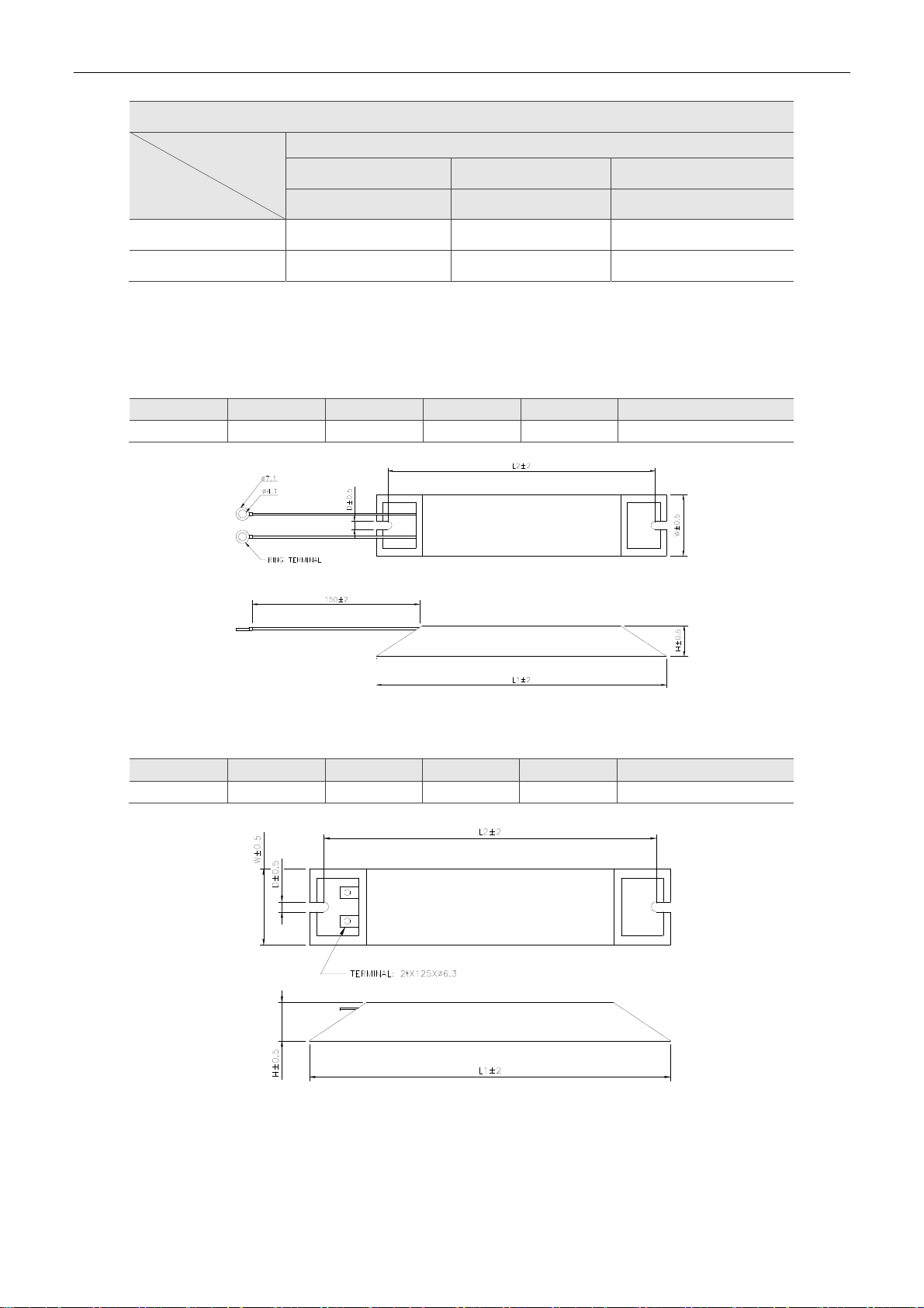
Dimensions of Regenerative Resistor
Delta Part Number: BR400W040 (400 W 40 Ω)
L1 L2 H D W MAX. WEIGHT (g)
265 250 30 5.3 60 930
2
Delta Part Number: BR1K0W020 (1 kW 20 Ω)
L1 L2 H D W MAX. WEIGHT(g)
400 385 50 5.3 100 2800
Note:
Please refer to Appendix B for selection of regenerative resistor.
September, 2015 2-11
Page 29

2
Installation ASDA-B2-F
(This page is intentionally left blank.)
2-12 September, 2015
Page 30

Wiring
This chapter explains the wiring methods of the power circuit an d connector definitions.
The standard wiring diagrams for each control mode are also provided.
3.1 Connections ····················································································· 3-2
3.1.1 Connecting to Peripheral Devices ··················································· 3-2
3.1.2 Connectors and Terminals of Servo Drive ········································· 3-3
3.1.3 Wiring Method ············································································ 3-4
3.1.4 Specification of Motor Power Cabl e ················································· 3-5
3.1.5 Specification of Encoder Cable Connector ········································ 3-7
3.1.6 Selection of Wiring Rod ······························································ 3-10
3.2 Basic Wiring ··················································································· 3-11
3.2.1 200 W or models below (withtout built-in regenerative resistor nor fan) ·· 3-11
3.2.2 400 W ~ 750 W models (with built-in regenerative resistor but no fan) ··· 3-12
3.2.3 1 kW ~ 1.5 kW models (with built-in regenerative resistor and fan) ······· 3-13
3.2.4 2 kW ~ 3 kW models (with built-in regenerative resistor and fan) ·········· 3-14
3.3 I / O Signal (CN1) Connection ···························································· 3-15
3.3.1 I / O Signal (CN1) Connector T erminal Layout ·································· 3-15
3.3.2 Signals Explanation of Connector CN1 ··········································· 3-16
3.3.3 Wiring Diagrams (CN1) ······························································· 3-18
3.3.4 DI and DO Signal Specified by Users ············································· 3-20
3.4 CN2 Connector ··············································································· 3-21
3.5 Wiring of CN3 Connector ·································································· 3-23
3.6 CN6 Connector (DMCNET) ································································ 3-24
3.7 Standard Connection Example ··························································· 3-26
September, 2015 3-1
Page 31

3
Wiring ASDA-B2-F
3.1 Connections
3.1.1 Connecting to Peripheral Devices
Power
100 W ~ 1.5 kW Single-/Three-phase 200 ~ 230 V
2 kW ~ 3 kW Three-phase 200 ~ 230 V
No Fuse Breaker (NFB)
It could prevent the instantaneous
excessive current caused by short-circuit
or fr om dam aging the s ervo drive when
power i s on / off.
Ma gnetic Cont ac tor (MC )
When an alarm occurs, it outputs
Regenerative
Resistor (Option)
EMI Filter
P+
C
ALRM signal and disconnect the
power of the servo dr ive.
L1c
L2c
R
S
T
U
V
W
P+
D
C
Θ
C
N
6
C
N
1
C
N
2
C
N
3
CN6 Conn ec tor
(DMCNET)
CN1 I/O Connector
CN2 Conn ector
CN3 Conn ector
Host Controller
It can connect to Delta’s PLC controller
or other brands of NC controllers.
1. For MODBUS communication and
To prevent the energy from flowing
back caused by motor brake and
result in error, please connect the P
and C end of the servo driv e to
external regenerative res istor, an d
the contact of P and D end sh ould
be opened. If usi ng the internal
regenerative resistor, please make
sure the contact of P and D end
sho uld be short-circu ited and the
con tact of P and C end should be
opened.
+
+
+
+
Moto r power
output U, V, W
Servo Motor
supports RS-232
2. Use AS DA-Soft to conduct tuning, parameters
setting and control.
Installation notes:
1. Check if the power and wiring among R, S, T and L
1c, L2c are correct.
2. Please check if the output terminal U, V, W of the servo motor is correctly wired. Incorrect
wiring may disable the operation of the motor or cause malfunction, triggering AL031
(Incorrect wiring of the motor power line U, V, W, GND).
3. When applying to the external regenerative resistor, the contact between P
should be opened and the external regenerative resistor should connect to terminal P
and C. When applying to the internal regenerative resistor, the contact between P
should be short-circuited and the contact between P
and C should be opened.
and D
and D
4. When an alarm occurs or the system is i n emergency stop st atus, use ALA RM or W ARN to
output and disconnect the power of magnetic contactor in order to disconnect the power of
servo drive.
3-2 September, 2015
Page 32

ASDA-B2-F Wiring
3.1.2 Connectors and Terminals of Servo Drive
Terminal
Signal
L1c, L2c
R, S, T
U, V, W
FG
P , D, C,
CN1 I/O connector (Option) Connect to the host controller. Please refer to section 3.3.
CN2
CN3
CN6 DMCNET Connector RJ45 connector. Please refer to section 3.6.
Power input of the
control circuit
Power input of the main
circuit
Motor cable
Regenerative resistor
terminal, braking unit, or
P
Ground terminal Connect to the ground wire of the power and servo motor.
Connector for encoder
(Option)
Connector for
communication (Option)
Name Description
Connect to single-phase AC power (Select the appropriate
voltage specification according to the product.)
Connect to three-phase AC power (Select the appropriate
voltage specification according to the product.)
Connect to the servo motor
Terminal
Symbol
U Red
V White
W Black
FG Green
Use internal resistor
Use external resistor
and .
Use external braking
unit
Connect to the encoder of the motor. Please refer to section 3.4.
Connect to RS-232. Please refer to section 3.5.
Wire
Color
Description
Three-phase main power cable of
the motor.
Connect to ground terminal (
of the servo drive.
The contact between P and D
end should be short-circuited;
contact between P and C end
should be opened.
Connect P , C ends to the resistor
and the contact between P
D end should be opened.
P and P of the brake unit
should connect to the resistor. The
contact between P
P and C should be opened. P
connects to the positive end of
V_BUS voltage;
the negative end of V_BUS
voltage.
3
)
and
and D and
connects to
Pay special attention to the followings when wiring:
1. When the power is cut off, do not touch R, S, T and U , V, W since the capacitance inside
the servo drive still contains huge amount of electric ch arge . Wait un til the char ging ligh t is
off.
2. Separate R, S, T and U, V, W from the other wires. The interval should be at least 30 cm
(11.8 inches).
3. If the wire of CN2 is not long enough, please use shielded twisted-pair cable which cannot
exceed 20 meters (65.62 inches). If it exceeds 20 meters, ple ase choose the bigger wire
diameter of signal cable to ensure it will not cause signal fading.
4. When selecting the wire rod, please refer to Section 3.1.6.
September, 2015 3-3
Page 33

3
Wiring ASDA-B2-F
3.1.3 Wiring Method
There are two types of wiring method, single-phase and three-phase. In the diagram below,
Power On is contact a, Power Off and ALRM_RY are contact b. MC is the coil of magnetic
contactor and self-remaining power and is the contact of main power circuit.
Wiring Method of Single-phase Supply (suitable for 1.5 kW and models below 1.5 kW)
RS
MCCB
Noise Filter
Power
Power
on
off
MC
ALRM_RY
MC
MC
R
S
T
L
1C
L
2C
SUP
U
V
W
Servo Drive
Wiring Method of Three-phase Power Supply (suitable for all serie s)
TS
R
MCCB
Noise Filter
Power onPower
off
MC
ALRM_RY
Motor
MC
R
S
T
L1C
L2C
MC
Servo Drive
SUP
U
V
W
Motor
3-4 September, 2015
Page 34

ASDA-B2-F Wiring
3.1.4 Specification of Motor Power Cable
Motor Model U, V, W / Connector of Brake
ECMA-C1040FS (50 W)
ECMA-Cᇞ0401S (100 W)
ECMA-Cᇞ0602S (200 W)
ECMA-Cᇞ0604S (400 W)
ECMA-Cᇞ0604H (400 W)
ECMA-Cᇞ08047 (400 W)
ECMA-Cᇞ0807S (750 W)
ECMA-Cᇞ0807H (750 W)
ECMA-Cᇞ0907S (750 W)
ECMA-Cᇞ0910S (1000 W)
ECMA-C1040FS (50 W)
ECMA-Cᇞ0401S (100 W)
ECMA-Cᇞ0602S (200 W)
ECMA-Cᇞ0604S (400 W)
ECMA-Cᇞ0604H (400 W)
ECMA-Cᇞ08047 (400 W)
ECMA-Cᇞ0807S (750 W)
ECMA-Cᇞ0807H (750 W)
ECMA-Cᇞ0907S (750 W)
ECMA-Cᇞ0910S (1000 W)
*:with brake
Terminal
Definition
3
A
B
ECMA-Gᇞ1303S (300 W)
ECMA-Eᇞ1305S (500 W)
ECMA-Gᇞ1306S (600 W)
ECMA-Fᇞ1308S (850 W)
ECMA-Gᇞ1309S (900 W)
ECMA-Cᇞ1010S (1000 W)
ECMA-Eᇞ1310S (1000 W)
ECMA-Fᇞ1313S (1300 W)
ECMA-Eᇞ1315S (1500 W)
ECMA-Fᇞ1318S (1800 W)
ECMA-Cᇞ1020S (2000 W)
ECMA-Eᇞ1320S (2000 W)
ECMA-Cᇞ13304 (3000 W)
ECMA-Eᇞ1820S (2000 W)
ECMA-Eᇞ1830S (3000 W)
ECMA-Fᇞ1830S (000 W)
C
D
September, 2015 3-5
Page 35

Wiring ASDA-B2-F
3
Wiring Name
Terminal
Definition A
Terminal
Definition B
Terminal
Definition C
Terminal
Definition D
When selecting the wire rod, please choose 600 V PVC cable and the length should be no lon ger
than 30 m. If the length exceeds 30 m, please take the received voltage into consideration wh en
selecting the wire size. Please refer to Section 3.1.6 for wire rod selection.
U
(Red)
1 2 3 4 - -
1 2 4 5 3 6
F I B E G H
D E F G A B
V
(White)
W
(Black)
CASE
GROUND
(Green)
BRAKE1
(Yellow)
BRAKE2
(Blue)
Note:
1. No polarity for brake coil, the wiring name is BRAKE1 & BRAKE2.
2. Power for brake is 24 V
3. Box, () in servo motor model represents brake or keyway / oil seal.
4. Triangle, (
△)
in servo motor model represents encoder type. Please see Chapter 1 for detail.
. Never share it with the power of control signal VDD.
DC
3-6 September, 2015
Page 36

ASDA-B2-F Wiring
3.1.5 Specification of Encoder Cable Connector
Encoder Connection (Diagram 1):
Servo Drive
3
C
N
6
C
N
1
C
N
2
C
N
3
CN2 Connector
*2
Encoder Cable
Quick Connec tor
Connector of
(Drive Si de)
*1
Connecto r of
Encoder Cable
(Motor Side)
Servo Motor
Note:
This diagram shows the connection between the servo drive and the motor encoder, which is not
drawn by the practical scale. The specification will change subject to the selected servo drive and
motor model.
1. Please refer to the Section of Specification and Definition of Encoder Connector.
2. Please refer to Section 3.4 CN2 Connector.
Motor Model Connector of Encoder Cable
ECMA-C1040FS (50 W)
ECMA-C△0401S (100 W)
ECMA-C△0602S (200 W)
ECMA-C△0604S (400 W)
ECMA-C△0604H (400 W)
ECMA-C△08047 (400 W)
3
6
9
2
5
8
7
4
1
View from
this sid e
View from
this sid e
3
6
9
2
5
8
1
4
7
ECMA-C△0807S (750 W)
ECMA-C△0807H (750 W)
ECMA-C△0907S (750 W)
ECMA-C△0910S (1000 W)
September, 2015 3-7
Page 37

Wiring ASDA-B2-F
Specification and Definition of Encoder Connector:
Connector of
Enco d er Ca b le
Connector of
Motor Encoder
3
Servo Drive
CN2
View from
this sid e
View from
this sid e
Motor
Encoder
(Encoder types are 17-bit and 20-bi t):
123
Blue
T+T-Reserved
Reserved
456
Blue/Black
Reserved Reserved
789
white
Black/Black
& white
Shield
Red/Red &
DC+5V GND
Reserved
6
Reserved
9
Shield
23
-
5
-
Blue Brown
1
White
T+
4
White/Red
T-
78
DC+5VGND
(Encoder type is 2500 ppr, 33 bits):
Th e wire co l or of the servo dri ve is for
ref erenc e only. Please refer to the
real objec t .
Reserved Reserved
6
Reserved Reserve d
23
5
9
Shield
1
2
Servo Drive
CN2
If not using housing and directly wire the cores, please follow the corresponding core number for wiring. For
example, core number 1 from the servo drive CN2 should connect to core number 1 from the motor encoder;
core number 2 from the servo drive CN2 should connect to core number 2 from the motor encoder and so on.
Please number the cores from the servo drive in order and then connect it to the encoder.
33
44
‧
‧
‧
1
2
‧
‧
‧
Blue
1
White
T+
4
White/Red
T-
78
Brown
DC+5VGND
Motor
Encoder
3-8 September, 2015
Page 38

ASDA-B2-F Wiring
Encoder Connection (Diagram 2):
Servo Drive
C
N
6
*1
CN2 Connector
C
N
1
C
N
2
C
N
3
Military
Connector
Connector of
Encoder Cable
3
Servo Motor
Note:
This diagram shows the connection between the servo drive and the motor encoder, which is not drawn by
the practical scale. The specification will change subject to the selected servo drive and motor model.
1. Please refer to Section 3.4, CN2 Connector.
Motor Model
ECMA-G△1303S (300 W)
ECMA-E△1305S (500 W)
ECMA-G△1306S (600 W)
ECMA-F△1308S (850 W)
ECMA-G△1309S (900 W)
ECMA-C△1010S (1000 W)
ECMA-E△1310S (1000 W)
ECMA-F△1313S (1300 W)
ECMA-E△1315S (1500 W)
ECMA-F△1318S (1800 W)
ECMA-C△1020S (2000 W)
ECMA-E△1320S (2000 W)
ECMA-C△13304 (3000 W)
ECMA-E△1820S (2000 W)
A
B
C
N
P
D
RS
E
G
Military Connector
Connector of Encoder Cable
M
L
T
K
J
HF
Pin
No.
A
Terminal
Identification
T+ Blue
B T -
S DC+5V
R GND
L
BRAID
SHIELD
Color
Blue&
Black
Red/Red&
White
Black/
Black&
White
–
Please select shielded multi-core and the shielded ca ble should connect to the SHIELD end.
Please refer to the description of Section 3.1.6.
Note:
1. Box, () in servo motor model represents brake or keyway / oil seal.
2. Triangle, (△) in servo motor model represents encoder type. Please refer to Chapter 1 for detail.
September, 2015 3-9
Page 39

Wiring ASDA-B2-F
3.1.6 Selection of Wiring Rod
The recommended wire rods are shown as the following table.
3
Servo Drive and corresponding
Servo Motor
ASD-B2-0121-F
ASD-B2-0221-F
ASD-B2-0421-F
ASD-B2-0721-F
ASD-B2-1021-F
ASD-B2-1521-F
ASD-B2-2023-F
ASD-B2-3023-F
ECMA-C1040FS
ECMA-C△0401S
ECMA-C△0602S
ECMA-C△0604S
ECMA-C△0604H
ECMA-C△08047
ECMA-E△1305S
ECMA-G△1303S
ECMA-F11305S
ECMA-C△0807S
ECMA-C△0807H
ECMA-C△0907S
ECMA-G△1306S
ECMA-C△0910S
ECMA-C△1010S
ECMA-E△1310S
ECMA-F△1308S
ECMA-G△1309S
ECMA-E△1315S
ECMA-C△1020S
ECMA-E△1320S
ECMA-E△1820S
ECMA-F11313S
ECMA-F11318S
ECMA-C△13304
ECMA-E△1830S
ECMA-E△1835S
ECMA-F△1830S
1.3 (AWG16) 2.1(AWG14) 0.82(AWG18) 2.1(AWG14)
1.3(AWG16) 2.1(AWG14) 1.3(AWG16) 2.1(AWG14)
1.3(AWG16) 2.1(AWG14) 2.1 (AWG14) 2.1(AWG14)
1.3(AWG16) 2.1(AWG14) 3.3 (AWG12) 2.1(AWG14)
Power Wiring - Wire Diameter mm2 (AWG)
L1c, L2c R, S, T U, V, W
P , C
Servo Drive Model
ASD-B2-0121-F
ASD-B2-0221-F
ASD-B2-0421-F
ASD-B2-0721-F
ASD-B2-1021-F
ASD-B2-1521-F
ASD-B2-2023-F
ASD-B2-3023-F
Size Number Specification Standard Length
0.13 (AWG26) 10 core (4 pairs) UL2464 3 m (9.84 ft.)
Encoder Wiring - Wire Diameter mm2 (AWG)
Note:
1. Please use shielded twisted-pair cable for encoder wiring so as to reduce the interference of the noise.
2. The shield should connect to the
3. Please follow the Selection of Wire Rod when wiring in order to avoid the danger it may occur.
4. Box, () at the end of the servo drive model represents the model code of ASDA B2-F. Please refer to
the model information of the product you purchased.
5. Box, () in servo motor model represents brake or keyway / oil seal.
6. Triangle, (
△) in servo motor model represents encoder type. Please refer to Chapter 1 for detail.
phase of SHIELD.
3-10 September, 2015
Page 40

ASDA-B2-F Wiring
3.2 Basic Wiring
3.2.1 200 W or models below (without regenerative resistor nor fan)
Connect to external
Power
1-phase/3-phase
200 ~ 230 V, 200 W and below
R
S
T
Detection
Phase Loss
regenerative resistor
P
Circuit
Rectifier
C
D
Servo Drive
IPM Module
Servo
U
Motor
V
Circuit
Regeneration
M
W
3
Digital Intput
A & B Output
Digital Output
Serial
Communication
RS-232
L1
C
L2
C
CN1
CN3
CN4Battery
±15V
+5V
+3.3V
Control Pow er
+24V
Protection
Circuit
GATE
DRIVE
Data Processing Unit
Display
MODE SHIFT
SETCHARGE
CN2
CN6
Encoder
DMCNET
September, 2015 3-11
Page 41

3
Wiring ASDA-B2-F
3.2.2 400 W ~ 750 W models (with built-in regenerative resistor but no fan)
Connect to external
Power
1-phase/3-phase
200 ~ 230 V, 400 W ~ 750 W
R
S
T
Detection
Phase Loss
regenerative resistor
P
Circuit
Rectifier
C
D
Regeneration
Circuit
Servo Drive
IPM Module
Servo
U
Motor
V
M
W
Digital Intput
A & B Output
Digital Output
Serial
Communication
RS-232
L1
C
L2
C
CN1
CN3
CN4Battery
±15 V
+5 V
+3.3 V
Control Power
+24 V
Protection
Circuit
Data Processing Unit
GATE
DRIVE
Display
MODE SHIFT
SETCHARGE
CN6
Encoder
CN2
DMCNET
3-12 September, 2015
Page 42

ASDA-B2-F Wiring
3.2.3 1 kW ~ 1.5 kW models (with built-in regenerative resistor and fan)
Connect to external
Power
1-phase/3-phase
200 ~ 230 V, 1 kW ~ 1.5 kW
regenerative resisto r
P
D
C
Servo Drive
Models of 1 kW or above
Digital Input
A & B Output
Digital Output
Serial
Communication
RS-232
IPM Module
R
S
T
Phase Loss
L1
C
L2
C
CN1
CN3
CN4Battery
Circuit
Rectifier
Detection
Circuit
Regeneration
±15 V
+5 V
+3.3 V
Control Pow er
+24 V
Protection
Circuit
GATE
DRIVE
Data Processing Unit
Displ ay
MODE SHIFT
+12 V
Servo
U
Motor
V
M
W
Encoder
CN2
SETCHARGE
3
CN6
DMCNET
September, 2015 3-13
Page 43

Wiring ASDA-B2-F
3.2.4 2 kW ~ 3 kW models (with built-in regenerative resistor and fan)
Connect to external
Power
3-phase
200 ~ 230 V, 2 kW ~ 3 kW
regenerative resistor
P
D
C
Servo Drive
Models of 1 kW or above
3
Digital Input
A, B Output
Digital Output
Serial
Communication
RS-232
L1
L2
IPM Module
R
S
T
Phase Loss
C
C
CN1
CN3
CN4Battery
Circuit
Rectifier
Detection
Circuit
Regeneration
±15 V
+5 V
+3.3 V
Protection
+24 V
Control Power
Circuit
GATE
DRIVE
Data Processing Unit
Display
MODE SHIFT
+12V
Servo
U
Motor
V
M
W
Encoder
CN2
SETCHARGE
CN6
DMCNET
3-14 September, 2015
Page 44

ASDA-B2-F Wiring
3.3 I / O Signal (CN1) Connection
3.3.1 I / O Signal (CN1) Connector Terminal Layout
In order to have a more flexible communication with the master (the host controller), 2
programmable Digital Outputs (DO) and 5 programmable digital inputs (DI) are provided. The
setting of 5 digital inputs and 2 digital outputs of each axis are parameter P2-10 ~ P2-14 and
parameter P2-18 ~ P2-19 respectively. In addition, the differential output encoder signal, A+, A-,
B+, and B- are also provided. The followings are the pin diagrams.
3
CN1 Connector (female)
Front View Rear View
5
10
15 11
Pin
Name Function
No
1 DI1- Digital input 6 GND
2 DI2- Digital input 7 OA
3 DI3- Digital input 8 /OA
4 DI4- Digital input 9 OB
DO2+ DO1+
Pin
No
DO1-DO2-
Name Function
Connector (male)
DI2-DI3-DI4- DI1-DI5-
Control Panel
Power 0 V
Encoder A
pulse output
Encoder /A
pulse output
Encoder B
pulse output
1
GND/OB OA/OAOB
COM+
Pin
No
11 COM+
12 DO1+ Digital output
13 DO1- Digital output
14 DO2+ Digital output
6
Name Function
Power ground
(12 ~ 24 V)
5 DI5- Digital input 10 /OB
Encoder /B
pulse output
15 DO2- Digital output
September, 2015 3-15
Page 45

Wiring ASDA-B2-F
3.3.2 Signals Explanation of Connector CN1
The following details the signals listed in previous section:
3
General Signals
Position Pulse
(Output)
Signal Pin No Function
OA
/OA
OB
/OB
7
8
Encoder signal output A and B (Line Drive
output)
9
10
Wiring Method
(Refer to 3.3.3)
C5/C6
Signal Pin No Function
The positive end of the external power
COM+ 11
Power
GND 6 Power of Control Panel 0 V
There are various operation modes available in this servo drive (please refer to Chapter 6.1 ) and
each mode requires different I/O signal configuration. Thus, prog rammable I/O signals are
provided. That is, users are able to choose DI and DO signals to meet different application
(+12 V ~ +24 V) must be connected to
COM+. COM+ is the common input of digital
input.
Wiring Method
(Refer to 3.3.3)
-
requirements. Basically, default setting of DI/DO signal has already have the appropriate function
which can satisfy the demand of general application.
Refer to the following DI/DO table to know the corresponding default setting of DI/DO signal and
Pin No of the selected mode in order to conduct the wiring.
The explanation of DO signal default setting is as follows.
Do Signal
Name
SRDY ALL - -
ZSPD ALL - -
Operation
Mode
Pin No
+ -
Function
When the servo drive applies to the power and no
alarm (ALRM) occurs in control circuit and motor
power circuit, this DO is ON.
When the motor speed is slower than the setting
value of parameter P1-38, this DO is ON.
Wiring Method
(Refer to 3.3.3)
C1,C2
Note:
1. For example, if Sz mode is selected, pin 3 and 2 are defined as DO.TSPD.
2. The unlisted Pin No means the signal is not the preset one. If users want to use it, parameters need to
be changed and set as the desired ones. Please refer to Section 3.3.4 for further detail.
3-16 September, 2015
Page 46

ASDA-B2-F Wiring
The explanation of DI signal default setting is as the following.
DI Signal
Name
ARST ALL -
EMGS ALL 5
NL
(CWL)
PL
(CCWL)
Operation
Mode
ALL 3
ALL 4
Pin No Function
When the alarm (ALRM) occurs, this signal is used to
reset the servo drive and enable DI.SRDY again.
It is contact B and always has to be ON; otherwise the
alarm (ALRM) will occur.
Reverse inhibit limit (contact B) and always has to be
ON; or the alarm (ALRM) will occur.
Forward inhibit limit (contact B) and always has to be
ON; or the alarm (ALRM) will occur.
Wiring Method
(Refer to 3.3.3)
C3,C4
The default setting of DI and DO in each operation mode is shown as the followings. The table
below is presented in a different way and the corresponding ope ration mode is put in the table in
order to avoid confusion.
Table 3.1
Default Value of DI Input Function
Symbol DI code Input Function DMC Sz Tz
3
ARST 0x02 Alarm reset DI5 DI5 DI5
EMGS 0x21 Emergency stop DI5 DI5 DI5
NL(CWL) 0x22 Reverse inhibit limit DI3 DI3 DI3
PL(CCWL) 0x23 Forward inhibit limit DI4 DI4 DI4
Note:
Please refer to Section 3.3.1 for corresponding pin from DI 1 ~ 5.
Table 3.2 Default Value of DO Input Function
Symbol DO code Input Function DMC Sz Tz
SRDY 0x01 Servo ready DO1 DO1 DO1
ZSPD 0x03 Zero-speed reached DO2 DO2 DO2
Note:
Please refer to Section 3.3.1 for corresponding pin from DO1 ~ 2.
September, 2015 3-17
Page 47

Wiring ASDA-B2-F
3.3.3 Wiring Diagrams (CN1)
When the drive connects to inductive loa d, the diode has to be inst alled. (The pe rmissible cu rrent
is under 40 mA. The surge current is under 100 mA.)
3
C1: Wiring of DO signal. The servo drive applies to
the external power and the resistor is general load.
C2: Wiring of DO signal. The servo drive applies to
the external power and the resistor is inductive
load.
Servo Drive
DOX: (DOX+,DOX-)
X = 1,2
DO1: (12,13)
DO2: (14,15)
24 V
DC
50 mA
DOX+
DOX-
R
24 V
DC
Servo Dr ive
DOX: (DO X + , DO X- )
X = 1,2
DO1: (1 2, 1 3)
DO2: (1 4, 1 5)
Input signal via relay or open-collector transistor
NPN transistor, common emitter (E) mode (SINK mode)
C3:The wiring of DI. The servo drive applies to the external power.
Servo Drive
DOX+
DOX-
Ensu r e th e polarity (+, -)
of dio de is c or r ect or it
may damage the dri v e .
24 V
DC
COM+
Approx. 4.7 KΩ
24 V
DC
SON
3-18 September, 2015
Page 48

ASDA-B2-F Wiring
PNP transistor, common emitter (E) mode (SOURCE mode)
C4: The wiring of DI. The servo drive applies to the external power.
Servo Drive
SON
24 V
DC
COM+
Approx. 4.7 KΩ
3
Caution: Do not apply to dual power or it may damage the servo drive.
C5: Encoder signal output (Line driver) C6: Encoder signal output (Opto-isolator)
Servo Dr iv e
AM26CS31Type
Max. output current is 20 mA
OA 7
/OA 8
OB 9
/OB 10
125 Ω
125 Ω
SG
Controller
Servo Dr ive
AM26CS31Type
Max. O utput current is 20 mA
OA 7
/OA 8
OB 9
/OB 10
Controller
200 Ω
200 Ω
SG
High spe ed
photocoupler
High spe ed
photocoupler
September, 2015 3-19
Page 49

Wiring ASDA-B2-F
3.3.4 DI and DO Signal Specified by Users
If the default setting of DI/DO does not fulfill the requirement for the application, users can
manually define the DI/DO signal. The signal function of DI 1 ~ 5, and DO1 ~ 2 is determined by
3
parameter P2-10 ~ P2-14 and parameter P2-18 ~ P2-19 respectively. Please refer to the
following table. Enter DI or DO code in the corresponding parameter to set up DI/DO.
Signal Name Pin No
DI1- CN1-1 P2-10
DI2- CN1-2 P2-11 DO1- CN1-13
Standard
DI
DI3- CN1-3 P2-12 DO2+ CN1-14
DI4- CN1-4 P2-13 DO2- CN1-15
DI5- CN1-5 P2-14 - - -
Corresponding
Parameter
Signal Name Pin No
DO1+ CN1-12
Standard
DO
Corresponding
Parameter
P2-18
P2-19
3-20 September, 2015
Page 50

ASDA-B2-F Wiring
3.4 CN2 Connector
CN2 encoder connector can be connected in two ways:
CN2 on drive side
CN2 Connector
Connect to the servo drive
The terminal block of the connector and pin number are as follows:
(A) CN2 Connector
View from
this side
Rear view of the terminal block
Encoder Conn e ct or
Connect to the motor
快速接頭
軍規接頭
6789
12345
3
(B) Encoder Connector
Quick Connector
Military Connector
123
4
56
789
View from
this side
B
C
D
E
A
M
N
P
T
RS
HF
G
2
1
3
6
5
4
7
9
View from
this side
L
K
J
8
September, 2015 3-21
Page 51

3
Wiring ASDA-B2-F
The definition of each signal is as follows:
Drive Connector Encoder Connector
Pin No
4 T+
5 T-
8 +5V +5 V power supply S 7
6, 7 GND Power ground R 8
Shell Shielding Shielding L 9 -
The shielding procedures of CN2 encoder connector are as followings:
Terminal
Symbol
Function and Description
Serial communication signal
input / output (+)
Serial communication signal input
/ output (-)
(1) Weld the metal core wires with shielding outside with
the metal part of the connector in order to have it fully
shielded.
Military
Connector
A 1 Blue
B 4 Blue & Black
Quick
Connector
Color
Red / Red &
White
Black / Black
& White
(2) Install the connector with shielding into the plasti c
case as shown in the figure.
(3) Tighten the screws to complete a shielded CN2
connector.
3-22 September, 2015
Page 52

ASDA-B2-F Wiring
3.5 Wiring of CN3 Connector
Layout of CN3 Connector
The servo drive can be connected to the personal computer via communication connector. Users
can operate the servo drive via MODBUS, PLC or HMI. The common communication inte rface,
RS-232, is provided and its communication dista nce is about 15 meters.
CN3 Connector (female)
Please carefully read through the
description below to avoid damage or
Side View
Pin No Signal Name Terminal Symbol Function and Description
1 Grounding GND + 5 V connects to the signal terminal
2
3 - - Reserved
4 RS-232 data receiving RS-232_RX
5 - -
RS-232 data
transmission
Rear View
RS-232_TX
danger caused by incorrect wiring!
The connector connects to RS-232 of PC
The connector connects to RS-232 of PC
The drive transmits the data
The drive receives the data
Reserved
3
6 - - Reserved
Note:
Two kinds of communication wire of IEEE1394 are commercially available. One of the internal ground
terminals (Pin 1) will short circuit with the shielding and will damage the drive. Do not connect GND to the
shielding.
September, 2015 3-23
Page 53

Wiring ASDA-B2-F
3.6 CN6 Connector (DMCNET)
CN6 uses the standard RJ45 connector, shielded communication cable, and connects to a host
controller or motion card. DMCNET system is used to implement position, torque and speed
3
mode. It also can read or monitor the drive status.
The station number of DMCNET is the same as RS-232. All are set via parameter P3-00 and the
transmission rate is up to 20 Mbps. For connecting more than one drives, it provides two sets of
communication connectors, one is for receiving and another is for transmission. The last servo
drive connects to a 120-Ω termination resistor.
CN6 Connector (female)
Pin No Signal Name Function and Description
1, 9 DMCNET_1A DMCNET Channel 1 bus line (+)
2, 10 DMCNET_1B DMCNET Channel 1 bus line (-)
3, 11 DMCNET_2A DMCNET Channel 2 bus line (+)
4, 12 - Reserved
5, 13 - Reserved
6, 14 DMCNET_2B DMCNET Channel 2 bus line (-)
7, 15 - Reserved
8, 16
Reserved Reserved
3-24 September, 2015
Page 54

ASDA-B2-F Wiring
Host Co ntroll er or
Motio n Card
…
Max. axes: 12
Max. cable length: 30 m
Note:
1. The terminating resistor is suggested to use 120 Ω (Ohm) 0.25 W or above.
2. The wiring method of concatenate more than one drives is based on two terminals of DMCNET . One is
for receiving and another one is for transmission. And the last servo drive conn ects to the termination
resistor. The wiring diagram of the termination resistor is shown as the followings:
Connect to the
terminal resisto r
3
September, 2015 3-25
Page 55

3
Wiring ASDA-B2-F
3.7 Standard Connection Example
Communication Mode
Servo Dr ive
ASDA-B2-F series
*1
4.7KΩ
4.7KΩ
4.7KΩ
4.7KΩ
4.7KΩ
4.7KΩ
*2
⊕
P
D
C
red
U
White
V
black
W
Green
Regenerative
Resistor
24V
BRKREMGS
*3
CN2
blue
T+
4
Blue/
black
Red/
Red&White
Black/
Black&
White
SG
6,7
T-
5
8
+5V
GND
CN6 DMCNET
1
DMCNET_1A
2
DMCNET_1B
3
DMCNET_2A
4
5
6
7
8
9
10
11
12
13
14
15
16
-
-
DMCNET_2B
-
-
DMCNET_1A
DMCNET_1B
DMCNET_2A
-
-
DMCNET_2B
-
-
Note:
*1 Please refe r t o Ch apter 3. 3. 3 for
C 3 ~ C6 wirin g diagrams ( SINK/
SOURCE mode).
*2 Models below 200 W have no
built- i n braki ng resi stor.
*3 The c oi l of brake has no pol arity.
*4 Single- phas e con necti ons ar e for
s ervo drives 1. 5 kW an d below onl y .
Power Supply
Brake
Encoder
Twisted- pair
or twisted-
shield cable
Data Input
Data Output
24V
Encoder
output
AC 200/230 V
Three-phase
50/60 Hz
24V_GND
differential signal
pulse
differential signal
Reserved
ORGP
EMGS
SRDY
ZSPD
A phase
B Phase
*4
24V
NL
PL
1.5 KΩ
1.5 KΩ
MCCB
MC
COM+
DI1
DI2
DI3
DI4
DI5
DO1+
DO1-
DO2+
DO2-
OA
/OA
OB
/OB
-
-
RS232_RX
-
RS232_TX
GND
R
S
T
L1c
L2c
CN1
11
1
2
3
4
5
12
13
14
15
7
8
9
10
CN3
6
5
4
3
2
1
3-26 September, 2015
Page 56

ASDA-B2-F Panel Display and Operation
Panel Display and
Operation
This chapter explains the panel display of ASDA-B2-F and its operation. Users may
check the operation status and see whether any alarm occurs via the panel.
4.1 Panel Description ·············································································· 4-2
4.2
Parameter Setting Procedure ································································ 4-3
4.3
Status Display ··················································································· 4-6
4.3.1 Save Setting Display ···································································· 4-6
4.3.2 Decimal Point ············································································· 4-6
4
4.3.3 Alarm Message ··········································································· 4-6
4.3.4 Positive and Negative Sign Setting ·················································· 4-7
4.3.5 Monitor Display ··········································································· 4-7
4.4
General Function ············································································· 4-10
4.4.1 Operation of Fault Record Display ················································· 4-10
4.4.2 JOG Mode ··············································································· 4-11
4.4.3 Force DO Output ······································································· 4-12
4.4.4 Digital Input Diagnosis Operation ·················································· 4-13
4.4.5 Digital Output Diagnosis Operation ················································ 4-14
September, 2015 4-1
Page 57

Panel Display and Operation ASDA-B2-F
4
4.1 Panel Description
Display
MODE Key
UP Key
Charge LED
Name Function
Display
SHIFT Key
SET Key
DOWN Key
Five-/Seven-segment display is for displaying the monitoring values,
parameter values and setting values.
The group code can be changed in Parameter Mode. When in Editing Mode,
moving the flashing bit to the left can adjust the higher setting bit. The display
of high/low digit can be switched in Monitor Mode.
Pressing the SET key can display and save the setting value. In monitor
mode, pressing the SET key can switch decimal or hexadecimal display. In
parameter mode, pressing the SET key can enter parameter setting mode.
Pressing the DOWN key can scroll through and change monitoring codes,
parameter groups and various parameter settings.
MODE
CHARGE
▲
▼
SHIFT
SET
DOWN Key
SHIFT Key
SET Key
UP key
Charge LED
MODE Key
Pressing the UP key can scroll through and change monitoring codes,
parameter groups and various parameter settings.
The Charge LED lights to indicate the power is applied to the circuit.
Pressing the MODE key can enter or exit different parameter groups, and
switch between Monitor mode and Parameter mode.
4-2 September, 2015
Page 58

ASDA-B2-F Panel Display and Operation
4.2 Parameter Setting Procedure
Switching the mode:
Power On
Monitoring
Mode
MODE
4
Parameter
Mode
MODE
Alarm Mode
MODE
Operating in each mode:
Monitoring mode
Monitoring
Mode
Please refer to Chapter 7 for parameters
1. If no alarm oc c urs, the A larm Mode will be skipped.
2. When new alarm occurs, it will switch to Alarm Mode in any
condition.
3. When sw itching to the oth er m ode , if no key is being selec ted
within 20 seconds, it will return to Alarm Mode automatically.
(Please refer to Chapter 9 for detailed alarm description.)
1. Pressing Keys can se lect mo nitoring
variables. (Please refer to section 4.3.5 for
further detail.)
2. U sers can directly enter th e code of
monitoring varia bles via P0-02. (please
refer to Chapter 7 for detailed de scription.)
‧‧‧‧
SET
Sw itch H i gh- / Lo w -di git
Switc h Hex. / Dec. format
SHIFT
September, 2015 4-3
Page 59

Panel Display and Operation ASDA-B2-F
Parameter Mode
Parameter Mode
4
Monitoring
Parameter P0
SHIFT
Basic
Paramete r P1
SHIFT
Extension
Parameter P2
SHIFT
Communication
Parameter P3
SHIFT
Diagnosis
Parameter P4
SHIFT
Motion Cont rol
Paramete r P5
‧‧‧
‧‧‧
‧‧‧
‧‧‧
‧‧‧
‧‧‧
MODE
Monitoring Mode
4-4 September, 2015
Page 60

ASDA-B2-F Panel Display and Operation
Edit Setting Mode
Parameter Mode
MODE SET
Editing Setti ng
Mode
SET
‧‧‧
4
Display pa rameter setting va lue
SHIFT
SHIFT
‧‧‧
MODE
Monitor ing /
Alar m Mode
If no alarm occurs, the Alarm Mode will be skipped.
Save the parame ter se tting value.
Then, r etur n to Paramete r Mode.
SET
‧‧‧
Save the parameter setting value.
Then, r etur n to Paramete r Mode.
SET
‧‧‧
Save the parameter setting value.
Then, r etur n to Paramete r Mode.
September, 2015 4-5
Page 61

Panel Display and Operation ASDA-B2-F
4.3 Status Display
4.3.1 Save Setting Display
When finishing editing parameter, press the SET Key to save the setting. The panel will display
4
the setting status according to the setting for a second.
Displayed Symbol Description
The setting value is saved correctly. (Saved)
Read-only parameter. Write-protected. (Read-Only)
Enter the wrong password or no password has been entered. (Locked)
Incorrect setting value or enter the reserved setting value. (Out of Range)
No entering is allowed when it is Servo ON. (Servo On)
Parameter will be effective after the servo drive is re-powered on. (Power On)
4.3.2 Decimal Point
Displayed Symbol Description
High byte / low byte indication: When the data is displayed in decimal 32 bits, it is
Negative Sign
Low Byte
High Byte
No Function
for indicating the current high or low byte.
Negative sign: When the data is displayed in decimal format, the two decimal
points in the left represents the negative sign, no matter it is showed in 16 or 32
bits. When it is showed in hexadecimal format, it only shows positive sign.
4.3.3 Alarm Message
Displayed Symbol Description
When alarm occurs, the servo drive will show ‘AL’ as the alarm sign and ‘nnn’ as
the alarm code. For further explanation, please refer to Chapter 7, P0-01,
parameter description, or Chapter 9, Troubleshooting.
4-6 September, 2015
Page 62

ASDA-B2-F Panel Display and Operation
4.3.4 Positive and Negative Sign Setting
Displayed Symbol Description
When entering the Editing Setting Mode, pressing the UP / DOWN Key can
change the displayed value. The SHIFT Key can change the carry val ue users
wish to alter. (The carry value is flashing at the moment.)
Pressing the SHIFT Key for two seconds can switch the positive (+) and negative
(-) sign. If the parameter value is over the range after switching the positive or
negative sign, then it cannot be switched.
4.3.5 Monitor Display
When the drive is applied to the power, the display will show the monitor displayed symbol for a
second, and then enter Monitoring Mode. In Monitoring Mode, the UP / DOWN Key can change
the monitoring variable. Or, the user can directly change parameter setting of P0-02 to set the
monitoring code. When applying to the power, the system will pre-set the monitoring code
according to the setting value of P0-02. For example, the setting value of P0-02 is 4. Every time
when applying to the power, it will display C-PLS monitor sign first, and then shows the input
4
pulse number of pulse command.
P0-02
Setting
Value
0
1
2
3
4
5
6
7
Monitor Displayed
Symbol
Description Unit
Motor feedback pulse number (after the scaling of
electronic gear ratio) (User unit)
Input pulse number of pulse command (after the scaling
of electronic gear ratio) (User unit)
The difference of error pulse number between control
command pulse and feedback pulse number (User unit)
Motor feedback pulse number (encoder unit) (1.28
million Pulse/rev)
Input pulse number of pulse command (before the
scaling of electronic gear ratio) (encoder unit)
Error pulse number (after the scaling of electronic gear
ratio) (encoder unit)
Input frequency of pulse command [Kpps]
Motor speed [r/min]
[user unit]
[user unit]
[user unit]
[pulse]
[pulse]
[pulse]
8
9
10
11
12
September, 2015 4-7
Speed input command [Volt]
Speed input command [r/min]
Torque input command [Volt]
Torque input command [%]
Average torque [%]
Page 63

Panel Display and Operation ASDA-B2-F
4
P0-02
Setting
Value
13
14
15
16
17
18
19
20
21
22
23
24
25
26
Monitor Displayed
Symbol
0
Z
+5000,
0
Z
+5000,
Description Unit
Peak torque [%]
Main circuit voltage [Volt]
Load / Motor inertia ratio (Note: If it shows 13.0, it
means the actual inertia is 13)
IGBT temperature
Resonance frequency (Low byte is the first resonance
and high byte is the second one).
The absolute pulse number of encoder Z phase equals
0
the homing value, 0. It will be +5000 or -5000 pulse
when rotating in forward or reverse direction.
Z
Mapping parameter #1: shows the content of parameter
P0-25 (specify the mapping target by P0-35)
Mapping parameter #2: shows the content of parameter
P0-26 (specify the mapping target by P0-36)
Mapping parameter #3: shows the content of parameter
P0-27 (specify the mapping target by P0-37)
Monitor variable #4: shows the content of parameter
P0-28 (specify the monitor variable code by P0-38)
Monitor variable #1: shows the content of parameter
P0-09 (specify the monitor variable code by P0-17)
Monitor variable #2: shows the content of parameter
P0-10 (specify the monitor variable code by P0-18)
Monitor variable #3: shows the content of parameter
P0-11 (specify the monitor variable code by P0-19)
Monitor variable #4: shows the content of parameter
P0-12 (specify the monitor variable code by P0-20)
[1 times]
[°C]
[Hz]
-
-
-
-
-
-
-
-
-
4-8 September, 2015
Page 64

ASDA-B2-F Panel Display and Operation
Example of the
displayed value
If the value is 1234, it displays 01234 (shows in decimal
(Dec)
(Hex)
(Dec high)
(Dec low)
(Hex high)
(Hex low)
Note:
1. Dec means it is displayed in decimal format. Hex means it is displayed in hexadecimal format.
2. The above display methods can be applie d in Monitoring Mode and Editing Setting Mode.
3. When all monitoring variables is 32 bits, high / low bit and the display (Dec/Hex) can be switched.
According to the definition in Chapter 7, each parameter only supports one displa ying method and
cannot be switched.
16 bits
32 bits
Negative display. If the value is -12345, it displays 1.2.345 (only shows
in decimal format; there is no positive or negative sign for hexadecimal
format display).
format).
If the value is 0x1234, it displays 1234 (shows in
hexadecimal format; the first digit does not show any).
If the value is 1234567890, the display of the high byte is
1234.5 and displays 67890 as the low byte (shows in
decimal format).
If the value is 0x12345678, the display of the high byte is
h1234 and displays L5678 as the low byte (shows in
hexadecimal format).
Status Description
4
September, 2015 4-9
Page 65

Panel Display and Operation ASDA-B2-F
4.4 General Function
4.4.1 Operation of Fault Record Display
When it is in Parameter Mode, select P4-00 ~ P4-04 and press the SET Key, the corresponding
4
fault record will be shown.
SET
SET
SET
SET
SET
The 1st recent error
The 2nd recent error
rd
recent error
The 3
th
recent error
The 4
The 5th recent error
4-10 September, 2015
Page 66

ASDA-B2-F Panel Display and Operation
4.4.2 JOG Mode
When it is in Parameter Mode, select P4-05 and follow the setting method below for JOG
operation.
1. Press the SET Key to display the speed of JOG. The default value is 20 r/min.
2. Press the UP or DOWN Key to adjust the desired speed of JOG. It is adjusted to 100 r/min
in the example.
3. Press the SET Key to display JOG and enter JOG mode.
4. When it is in JOG Mode, press the UP or DOWN Key to enable the servo motor in forward
or reverse direction. The servo motor stops running as soon as the user stops pressing the
key. JOG operation is working only when it is Servo ON.
SET
Display JOG speed.
Its defa ul t value is 20 r/m i n .
Press Up / Do wn K e y to a dj ust JOG speed.
4
…
Adjust to 100 r/mi n .
SET
Dis pla y JO G and ent e r JOG Mode .
JOG Mode
P(CCW) N(CW)
MODE
Exit
September, 2015 4-11
Page 67

Panel Display and Operation ASDA-B2-F
4
4.4.3 Force DO On
Enter the Diagnosis Mode by the following settings. Set P2-08 to 406 and enable the function of
force DO on. Then, set the forced DO by binary method via P4-06. When the set ting value i s 2, it
will force to enable DO2. When the setting value is 5, it will force to enable DO1 and DO3. No
data is retained in this mode. It returns to the normal DO mode when re-power on the drive or set
P2-08 to 400.
SET
SET
Force to enable
DO mod e
SET
Force to enable DO1
Fo rce to enabl e D O2
Fo rce to enabl e D O1 and DO2
Note:
P4-06 is displayed in hexadecimal format. Therefore, it will not show the fifth 0.
4-12 September, 2015
Page 68

ASDA-B2-F Panel Display and Operation
4.4.4 Digital Input Diagnosis Operation
Enter the Diagnosis Mode – DI by the following setting methods. When the external output signal
DI1 ~ DI5 is ON, the corresponding signal will be shown on the panel. It is displayed by bit. When
it shows bit, it means the DI is ON.
For example, if it shows 001E, E is in hexadecimal format, it will be 1110 when it transfers to
binary format. Then, DI2 ~ DI4 is ON.
SET
The panel di s pl ays in
hexad ecim al for mat.
4
00 0000 0001 1110
DI14DI13DI12DI11DI10DI9DI8DI7DI6DI5DI4DI3DI2DI
1
(Display in hexadecimal format)
Binary code
Corres ponding
DI Status
September, 2015 4-13
Page 69

Panel Display and Operation ASDA-B2-F
4
4.4.5 Digital Output Diagnosis Operation
Enter the Diagnosis Mode – DO by the following setting methods. The output signal DO1 ~ DO2
is ON and the corresponding signal will be shown on the panel. It is displayed by bit. When it
shows 1, it means the DO is ON.
For example, if it shows 03, 3 is in hexadecimal format, it will be 0011 when it transfers to binary
format. Then, DO1~DO2 is ON.
0000 0011
(Displ ay in hexadeci m al format)
SET
Th e panel displays in
hexad ecimal form at .
Binar y Code
DO2DO
1
Corresponding
DO Status
4-14 September, 2015
Page 70

Trial Operation and Tuning
This chapter illustrates how to do trial operation and the basic procedure of tuning. For
your safety, please conduct the first inspection (without load) and then carry out further
trial with load.
5.1 Inspection without Load ······································································ 5-2
5.2 Apply Power to the Servo Drive ···························································· 5-3
5.3 JOG Trial Run without Load ································································· 5-7
5.4 Trial Run without Load (Speed Mode) ···················································· 5-8
5.5 Tuning Procedure ············································································ 5-10
5.5.1 Flowchart of Tuning Procedure ······················································5-11
5.5.2 Inertia Estimation Flowchart (with Mechanism) ································· 5-12
5.5.3 Flowchart of Auto T uning ····························································· 5-13
5.5.4 Flowchart of Semi-Auto Tuning ····················································· 5-14
5.5.5 Limit of Inertia Ratio ··································································· 5-15
5.5.6 Mechanical Resonance Suppression Method ·································· 5-17
5.5.7 Tuning Mode and Parameters ······················································ 5-18
5.5.8 Tuning in Manual Mode ······························································· 5-19
September, 2015 5-1
Page 71

Trial Operation and Tuning ASDA-B2-F
5.1 Inspection without Load
Please remove the load from the servo motor , in cluding couplin g on the shaft and acce ssories so
as to avoid any damage to servo drive or mechanism. This is for avoiding the falling off of the
5
disassembled parts of the motor shaft and indirectly causing the personnel injury or equipment
damage during operation. Running the motor without load, if the servo motor can run during
normal operation, then it can operate with load.
Caution: To avoid danger, please operate the servo motor without load first and ensure it
runs normally. Then, operate the motor with load.
Please carefully check the following items before operation to avoid any damage to the motor.
Inspection before operation (not applied to the power )
Check if there is any obvious damage shown on its appearance.
The splicing parts of the wiring terminal should be isolated.
Make sure the wiring is correct so as to avoid the damage or any abnormity.
Make sure electric conductivity objects including sheetmetal (such as screws) or inflammable objects
are not in the servo drive.
Make sure the control switch is OFF.
Do not place the servo drive or external regenerative resistor on inflammable objects.
To avoid the electromagnetic brake losing efficacy, please check if stop function and circuit break
function can work normally.
If the peripheral devices are interfered by the electronic instruments, please reduce electromagnetic
interference with devices.
Please make sure the external voltage level of the servo drive is correct.
Inspection when running the servo drive (already applied to the power)
The encoder cable should avoid excessive stress. When the motor is running, make sure the cable is
not frayed or over extended.
Please contact with Delta if there is any vibration of the servo motor or unusual noise during the
operation.
Make sure the setting of the parameters is correct. Different machinery has different characteristic,
please adjust the parameter according to the characteristic of each machinery.
Please reset the parameter when the servo drive is in Servo Off status, or it may cause malfunction.
When the relay is operating, make sure it can work properly.
Check if the power indicator and LED display works normally.
5-2 September, 2015
Page 72

ASDA-B2-F Trial Operation and Tuning
5.2 Apply Power to the Servo Drive
Please follow the instructions below.
A. Make sure the wiring between the motor and servo drive is correct:
U, V, W and FG have to connect to cable red, white, black and green respectively. If the
wiring is incorrect, the motor cannot work normally. The ground wire FG of the motor must
be connected to the ground terminal of the servo drive. Please refer to Chapter 3.1 for
wiring.
The encoder cable of the motor has correctly connected to CN2: If users only desire to
carry out JOG function, connecting CN1 and CN3 is not needed (Please refer to Chapter
5.3). Refer to Chapter 3.1 and 3.4 for the wiring of CN2.
Caution: Do not connect the power (R, S, T) to the output terminal (U, V, W) of the servo
drive. Or it might damage the servo drive.
B. Power circuit of the servo drive:
Apply power to the servo drive. Please refer to Chapter 3.1.3 for power wiring.
C. Power on:
Power of the servo drive: including control circuit (L1c, L2c) and main circuit (R, S, T) power.
When the power is on, the display of the servo drive will be:
5
The default of digital input (DI3 ~ DI5) are the signal of reverse inhibit limit (NL), forward inhibit
limit (PL), and emergency stop (EMGS), if DI3 ~ DI5 is not used, adjusting the setting of P2-12 ~
P2-14 is a must, which can be set to 0 (disable this DI function) or modified to another function.
From the last setting, if the servo drive status displays parameter P0-02 setting as the motor
speed (07), then the screen display will be:
When the panel displays no text, please check if the power of control circuit is undervoltage.
September, 2015 5-3
Page 73

Trial Operation and Tuning ASDA-B2-F
5
(1) When the screen displays
Warning of overvoltage:
It means the voltage input by the main circuit is higher than the rated range or a power input error
has occurred (incorrect power system).
Corrective action:
Use the voltmeter to measure if the input voltage from the main circuit is within the range of
rated voltage.
Use the voltmeter to measure if the power system complies with the specifications.
(2) When the screen displays
Warning of encoder error:
Check if the motor encoder is securely connected and the wiring is correct.
Corrective action:
Make sure the wiring is the same as the instruction of the user manual.
Check the encoder connector.
Check if the wiring is loose.
Check if the encoder is damaged. If yes, please change a new one.
5-4 September, 2015
Page 74

ASDA-B2-F Trial Operation and Tuning
(3) When screen displays
Warning of emergency stop:
Please check if any of the digital input DI1 ~ DI5 is set to emergency stop (EMGS).
Corrective action:
If not desire to set emergency stop (EMGS) as one of the digital input, make sure no digital
input is set to emergency stop (EMGS) among DI1 ~ DI5. (That is to say none of the
parameters, P2-10 ~ P2-14 is set to 21.)
If the function of emergency stop (EMGS) is needed and this DI is set as normally close
(function code: 0x0021), please make sure this DI is always normally close. If not, please
set this DI as normally open (function code: 0x0121).
(4) When screen displays
Warning of negative limit error:
Please check if any of the digital input DI1 ~ DI5 is set to negative limit (NL) and that DI is ON.
5
Corrective action:
If not desire to set negative limit (NL) as one of the digital input, make sure no digital input is
set to negative limit (NL) among DI1 ~ DI5. (That is to say none of the parameters, P2-10 ~
P2-14 is set to 22.)
If the function of negative limit (NL) is needed and this DI is set as normally close (function
code: 0x0022), please make sure this DI is always normally close. If not, please set this DI
as normally open (function code: 0x0122).
(5) When screen displays
Warning of positive limit error:
Please check if any of the digital input DI1 ~ DI5 is set to positive limit (PL) and that DI is ON.
Corrective action:
If not desire to set positive limit (PL) as one of the digital input, make sure no digital input is
set to positive limit (PL) among DI1 ~ DI5 (That is to say none of the parameters, P2-10 ~
P2-14 is set to 23.)
September, 2015 5-5
Page 75

Trial Operation and Tuning ASDA-B2-F
5
If the function of positive limit (PL) is needed and this DI is set as normally close (function
code: 0x0023), please make sure this DI is always normally close. If not, please set this DI
as normally open (function code: 0x0123).
(6) When screen displays
Warning of overcurrent:
Corrective action:
Check the connection between the motor and servo drive.
Check if the conducting wire is short circuited.
Exclude short circuit and avoid metal conductors being exposed.
(7) When screen displays
Warning of undervoltage:
Corrective action:
Check if the wiring of main circuit input voltage is correct.
Use voltmeter to measure if the main circuit voltage is normal.
Use voltmeter to measure if the power system complies with the specification.
Note:
During power on or servo on (without issuing any command), if an alarm occurs or any abnormal display is
shown, please contact the distributors.
5-6 September, 2015
Page 76

ASDA-B2-F Trial Operation and Tuning
5.3 JOG Trial Run without Load
It is very convenient to test the motor and servo drive with the method of JOG trial run without
load since the extra wiring is unnecessary. For safety reasons, it is recommended to set JOG at
low speed. Please see the following descriptions.
Step 1: Use software setting to Servo On the drive. Set parameter P2-30 to 1. This setting is to
force servo on the drive through software.
Step 2: Set P4-05 to JOG speed (Unit: r/min). After setting the desired JOG speed, press the
SET key, the servo drive will enter JOG mode.
Step 3: Press the MODE key to exist JOG mode.
5
Moto r runs in
forward direction
Motor runs in
re vers e di rection
Release PressPress
If the mo tor d oes not ru n, ple ase c heck if the w i ri ng betw een UV W and enc oder ca bl e i s cor rect .
If the mo tor r uns abnor m al l y, pleas e chec k if t he UV W phas e sequ ence is c orrect.
Motor stopsSpeed 0
September, 2015 5-7
Page 77

Trial Operation and Tuning ASDA-B2-F
5.4 Trial Run without Load (Speed Mode)
Before starting trial run without load, firmly secure the motor base so as to avoid the danger
caused by the reacting force generated during speed change.
5
Step 1: Set the control mode of the servo drive to speed mode. Set P1-01 to 2 as speed mode.
Then, re-power on the servo drive.
Step 2: In speed mode, the digital input settings of trial run are as follows:
Digital Input
DI1 P2-10 = 101
DI2 P2-11 = 104 CCLR Pulse Clear DI2- = 2
DI3 P2-12 = 114 SPD0 Speed Selection DI3- = 3
DI4 P2-13 = 115 SPD1 Speed Selection DI4- = 4
DI5 P2-14 = 0 Disabled DI disabled DI5- = 5
The above table shows the settings that disable the function of negative limit (DI3), positive limit
(DI4) and emergency stop (DI5). Thus, parameter P2-14 is set to 0 (Disabled); DI3 and DI4 are
set to Speed Selection (SPD0) and Speed Selection (SPD1) respectively. The digital input of
Parameter Setting
Value
Symbol Function Description CN1 Pin No
SON
Servo ON
DI1- = 1
Delta’s servo drive can be programmed by users. When programming digital input, please refer
to the description of DI code.
The default setting includes the function of negative limit, positive limit and emergency stop;
therefore, if any alarm occurs after setting completed, please re-power on the servo drive or set
DI.ARST to On to clear the alarm. Please refer to Chapter 5.2.
5-8 September, 2015
Page 78

ASDA-B2-F Trial Operation and Tuning
The speed command selection is determined by SPD0 and SPD1. See the table below.
Speed
Command No.
S1 0 0 N/A
S2 0 1
S3 1 0 P1-10 -60000 ~ 60000
S4 1 1 P1-11 -60000 ~ 60000
0 means DI is Off; 1 means DI is On
DI signal of CN1
SPD1 SPD0
Command Source
Register
parameter
Content Range
Speed command
is zero
P1-09 -60000 ~ 60000
0
Register parameter
The parameter setting range is from -60000 to 60000. Setting speed = Setting range x unit (0.1
r/min).
For example: P1-09 = +30000; Setting speed = +30000 x 0.1 r/min = +3000 r/min
Command setting of speed register
Set parameter P1-09 to 30000
Input command Rotation direction
5
Set parameter P1-10 to 1000
Set parameter P1-11 to -30000.
Step 3:
(1) Switch ON DI 1 and Servo On.
(2) Both DI 3 (SPD0) and DI 4 (SPD1), the speed command, are OFF, which means it
currently executes S1 command. The motor rotates according to analog voltage
command.
(3) When DI3 (SPD0) is ON, it means it currently executes S2 command (3000 r/min). The
rotation speed is 3000 r/min for rotary motor.
(4) When DI4 (SPD1) is ON, it means it currently executes S3 command (100 r/min). The
rotation speed is 100 r/min.
(5) When both DI3(SPD1) are ON, it means S4 command (-3000 r/min) is executed at the
moment. The rotation speed is -3000 r/min.
(6) Step (3), (4) and (5) can be repeatedly executed.
(7) If users desire to stop the motor, switch of f DI1 (Servo Off).
+ CCW
- CW
September, 2015 5-9
Page 79

Trial Operation and Tuning ASDA-B2-F
5.5 Tuning Procedure
Estimate the inertia ratio: JOG Mode
1. After completing wiring, when applying to the power, the servo drive will
display:
AL013
5
2. Press the MODE key to select the mode of parameter function.
3. Press the SHIFT key to select the mode of parameter group.
4. Press the UP key to select parameter P2-17.
5. Press the SET key to display parameter value, which is shown as the content
on the right.
6. Press the SHIFT key t wice, then press the UP key and then press the SET
key.
7. Press the UP key to select parameter P2-30.
8. Press the SET key to display the parameter value.
9. Press the UP key and select the parameter value 1.
10. Then, the servo drive is ON and will show:
11. Press the DOWN key to select the estimated inertia ratio.
12. The panel displays the current value of inertia ratio (default value).
P0-00
P2-00
P2-14
21
121
P2-30
0
1
00000
J-L
1.0
13. Press the MODE key to select the mode of parameter function.
14. Press the SHIFT key to select the mode of parameter group.
15. Press the UP key to select parameter P4-05.
16. Press the SET ke y to show the content, which is 20 r/min at JOG speed.
Press the UP and DOWN key to raise or reduce the JOG speed. Press the
SHIFT key to move to the next digit of the left.
17. Set the desired JOG speed and press the SET key. Then, the figure
displays as shown on the right.
18. Press the UP key to rotate the motor in forward direction or press the DOWN key the motor will rotate in
reverse direction.
19. Carry out JOG operation at low speed first. With the constant speed, if the motor operates smoothly in
forward and reverse direction, users can carry out JOG operation at higher speed.
20. In P4-05, the servo drive cannot display inertia ratio. Please press the MODE key twice to view the
value of inertia ratio. If users desire to start JOG operation again, press the MODE key, and then press
the SET key twice. Observe the panel display to see if the load inertia ratio remains at the same value
after acceleration and deceleration.
P2-30
P4-00
P4-05
20
200
-JOg-
5-10 September, 2015
Page 80

ASDA-B2-F Trial Operation and Tuning
5.5.1 Flowchart of Tuning Procedure
Trial run without load
is OK.
No
Exit the control of the host controller.
Use the servo drive to perform trial
run and estimate the inertia ratio*
Manual mode Semi-auto mode Auto mode
Connect to the host controller. Pay
attention to the wiring of CN1. Perform
Use the selected gain tuning mode
New model?
Yes
trial run by P4-07 and P4-09.
to enhance the performance.
OK
Note: The value o f inertia ratio is used for rotary motors.
Figure 5-1 Tuning procedure
5
If the estimation of inertia ratio is
incorrect, it cannot obtain the best
performance of tuning.
Resonance can be suppressed
by P2-23 and P2-24.
September, 2015 5-11
Page 81

Trial Operation and Tuning ASDA-B2-F
5.5.2 Inertia Estimation Flowchart (with Mechanism)
Tu rn Off the po wer of servo d rive .
5
Decre ase the value of P 2-00. Set
the valu e of P 2 - 06 an d P 2 - 00 to
the same.
Connect th e motor to the
mechanism.
Tu rn On th e power of serv o drive.
Set P0-02 to 15. The panel will
display iner tia ra tio .
Set P2 - 32 to 0 i n m anual m ode.
Set P2-30 to 1.
No
Yes
Mechanical
sys t em v i brat es ?
Enter P4-05, JOG mo de.
Set JOG sp eed at 20 r/m i n .
Press the Up (f o rward) or Down
(reve r se ) key to perf or m JOG.
If it operates
smoothly at constan t
speed?
Yes
Inc reas e JOG spee d which is >
200 r / m i n .
Alt ernat el y acce lerat e and
decelerate the mechanical
system.
View th e panel display to see if th e i nert i a rat i o remai ns t he same after
alternately acceleration and deceleration. Then, select the tuning
me thod a ccor di ng to the inerti a ratio *.
Note: Users cannot view inertia ratio in JOG mode. Please press the
MODE Key twice. If users desi r e to perform JOG opera tion, press th e
MOD E Key , and t h en pre ss the SET Key tw i ce.
No
Check the
mechanism.
Note: The value o f inertia ratio is used for rotary motors.
Figure 5-2 Inertia estimation
5-12 September, 2015
Page 82

ASDA-B2-F Trial Operation and Tuning
5.5.3 Flowchart of Auto Tuning
Please refer to the figure below to start the auto tuning procedure.
Servo off. Set P2-32 to 1. Then, Servo on.
Set P0-02 to 15. The panel
will display th e inertia ratio*.
Alternately accelerate and
decelerate.
1. Decrease the value of P2-31 to
reduce the noise.
2. If not decrease the value of P2-31,
then adjust the value of P2-23 and
P2-24 to suppress the resonance.
(Please refer to Chapter 5.6.6)
Yes
Any resonance?
No
5
Satisfactory
performance?
No
Increase the value of P2-31 to increase the
response and stiffness.
Note: The value of inertia ratio is used for rotary motors.
Figure 5-3 Tuning procedure in auto mode
Yes
Tuning
completed.
Set P2-32 to 1 (auto mode, continuous tuning):
The servo will continue to estimate the system inertia. Then, it will automatically store the
value in P1-37 every 30 minutes and refer the stiffness and bandwidth setting of P2-31.
Adjust the value of P2-31, Stiffness setting in auto tuning mode (The default value is 40):
Increase the value of P2-31 to increase stiffness or decrease to reduce noise. Please note
that the higher the value is, the higher the stiffness will be. Continu e to tune the system until
the performance is satisfied. Then, tuning is completed.
In auto and semi-auto mode, the bandwidth setting of speed circuit is as follows.
1 ~ 50 Hz: low-stiffness, low-response
51 ~ 250 Hz: medium-stiffness, medium-response
251 ~ 850 Hz: high-stiffness, high-response
September, 2015 5-13
Page 83

Trial Operation and Tuning ASDA-B2-F
5.5.4 Flowchart of Semi-Auto Tuning
Please refer to the figure below to start the semi-auto tuning procedure.
5
1. Lower the value of P2-31 to reduce the noise.
2. If not desire to lower the value of P2-31, value
of P2-23 and P2-24 can be used to suppress
the resonance as well.
(Please refer to Chapter 5.6.6)
Servo off an d s et P2 -3 2 to 2 . Then, ser vo on
Set P0-02 to 15. The panel
displ ay s t he ine rt i a rat i o*.
Th e se rv o drive issues the
command and make motor
Yes
Th e i nerti a ratio shown on t he
panel is stable. Check if bit 0 of
again.
al t ernately accel erate /
decelerate.
Any
resonance?
No
P2-33 is 1*
Yes
No
Increase the valu e of P2-31
Satisfactory
perf ormance?
Yes
Complete
Figure 5-4 Procedure of tuning in semi-auto mode
No
to increase resp onse and
stiffness.
Set P2-32 to 2. (semi-auto mode, non-continuous tuning)
After tuning for a while and wait until the system inertia is stable, it stops estimating. The
estimated inertia ratio will be saved to P1-37. When switching mode from manual or auto to
semi auto, the system starts tuning again. During the process of estimation, the system will
refer to the stiffness and bandwidth setting of P2-31.
Adjust the value of P2-31, Response setting in auto mode (The default value is 40)
Increase the value of P2-31 to increase the response or decrease to reduce the noise.
Continue to tune the system until the performance is satisfied. Response setting in
semi-auto tuning mode: the higher the value is, the better the response will be. Then, tuning
is completed.
In auto and semi-auto mode, the bandwidth setting of speed circuit is:
1 ~ 50 Hz: low-stiffness, low-response
51 ~ 250 Hz: medium-stiffness, medium-response
251 ~ 850 Hz: high-stiffness, high-response
Note:
1. If P2-33 bit 0 is set to 1, it means the inertia estimation in semi-auto mode is completed. The result can be
accessed by P1-37.
2. If the value of P2-33 bit 0 is cleared to 0, the system will start to estimate again.
5-14 September, 2015
Page 84

ASDA-B2-F Trial Operation and Tuning
5.5.5 Limit of Inertia Ratio
Please see the limit of inertia ratio below during the estimation.
Acceleration / Deceleration time of reaching 2000 r/min should be less than 1 second.
The speed in forward and reverse direction should be higher than 200 r/min.
The load inertia should be under 100 times of motor inertia.
The change of external force of inertia ratio cannot be too severe.
In auto mode, the inertia value will be saved to P1-37 every 30 minutes; while in semi-auto mo de,
the inertia value will be saved to P1-37 only until the system inertia is stable and stops the
estimation of load inertia.
5
1. Lower the value of P2-31 to reduce the noise.
2. If not desire to lower the value of P2-31, value
of P2-23 and P2-24 can be used to suppress the
resona nce as well.
(Please refer to Chapter 5.6.6)
Servo off an d s et P2 - 32 t o 2 . Then , Se rvo on
Set P0-02 to 15. The panel
dis pla ys The inertia ratio*.
Th e se rvo dr i ve i ss ues the
command and to make motor
Yes
again.
al t ernately acce l erate /
decelerate.
Any
resonance?
No
Th e inert i a ratio shown on
the panel is stable.
Yes
Satisfactory
performance?
Incre ase the value of P2-31
No
to increase response and
No
stiffness.
Yes
If the value of inertia ratio
remains almost the same, then
ser v o off an d s et P2 - 32 to 0.
Yes
Complete
Figure 5-5 Estimation of load inertia
September, 2015 5-15
Page 85

Trial Operation and Tuning ASDA-B2-F
Moto r al ternately ac celerate s
and dece l erat es
5
High-frequency
resonance?
Yes
Set P2-47 to 1
Resonance
elimminated?
Yes
Set P2-47 to 0
Complete
No
Comp lete
No
Repeat edly s et P 2 -47
to 1 for over 3 times
Note 1
P2-44 = 32 (max);
P2-46 = 32 (max)
Note 2
It is suggeste d to reduce the
speed ba ndwidth.
No
Yes
Yes
No
P2-47 is s et to 0
Remain the value of P2-43
and P2-45
Sup press resona nce by P2 -
44 and P2-46.
Motor alternately accelerates
and dece l erat es
Yes
No
High-frequency
resonance?
Figure 5-6 Procedure of auto suppressing the resonance
Note:
1. Resonance suppression is determined by parameter P2-44 and P2-46. If the value has been set to the
maximum (32 dB), and still cannot suppress the resonance, please reduce the speed bandwidth. After
setting P2-47, users can check the value of P2-44 and P2-46. If the value of P2-44 is not 0, it means the
resonance frequency exists in the system. Then, users can access P2-43 to see the resonance
frequency (Hz). When there is another resonance fre qu enc y, the information will be shown in P2-45 and
P2-46.
2. If resonance still exists, repeatedly set P2-47 to 1 for more than 3 times and manually adjust the setting of
resonance.
5-16 September, 2015
Page 86

ASDA-B2-F Trial Operation and Tuning
5.5.6 Mechanical Resonance Suppression Method
Three groups of Notch filter are provided to suppress mechanical resonance. Both two of them
can be set to the auto resonance suppression and manual adjustment.
Use the anal y tic tool prov i ded by PC
software to display the point of
resonance.
Th e serv o i ssu es the co m m a nd t o
make motor accel era te / dec ele rate
alternatively
High-frequency
resonance?
Yes
Sav e t he value of reso nanc e fr equenc y t o P2 - 23
and set P2- 24 to 4.
Resonance
eliminated?
No
Complete
No
5
Incre ase the value of
P2-24
Yes
Tuning completed
Figure 5-7 Procedure of manual suppressing the resonance
September, 2015 5-17
Page 87

Trial Operation and Tuning ASDA-B2-F
5.5.7 Tuning Mode and Parameters
5
Tuning mode P2-32
Manual mode 0 (default) N/A
Auto mode
(continuous
estimation)
Semi-auto mode
(non-continuous
estimation)
1
2
Auto-set
parameters
P1-37
P2-00
P2-04
P2-06
P2-25
P2-26
P2-49
P1-37
P2-00
P2-04
P2-06
P2-25
P2-26
P2-49
User-defined parameters Inertia adjustment
P1-37(Inertia ratio of the motor)
P2-00 (Position control gain)
P2-04 (Speed control gain)
P2-06(Speed integral
compensation)
P2-25(Low-pass filter of
resonance suppression)
P2-26 (Anti-interference gain)
P2-31 Frequency response of
speed loop setting in auto mode
(response level)
P2-31 Frequency response of
speed loop setting in semi-auto
mode (response level)
The value remains
Continuous tuning
(update the inertia
every 30 minutes)
Non-continuous
tuning (stop
updating the
inertia after
operating for a
while)
When switching mode from auto mode 1 to manual mode 0, the value of P2-00, P2-04, P2-06,
P2-25, P2-26 and P2-49 will be modified to the one in auto mode.
When switching mode from semi-auto mode 2 to manual mode 0, the value of P2-00, P2-04,
P2-06, P2-25, P2-26 and P2-49 will be modified to the one in semi-auto mode.
5-18 September, 2015
Page 88

ASDA-B2-F Trial Operation and Tuning
5.5.8 Tuning in Manual Mode
The selection of position / speed response frequency should be determined by the machinary
stiffness and application. Generally, the high-frequency machinary or the one requries precise
processing needs the higher response frequency. However, it might cause the resonance. Thus,
use machinery with higher stiffness is needed so as to avoid resonance. When the permitted
resonace frequnecy is unknown, users could gradually increase the gain setting value to
increase the resonse frequency. Then, decrease the gain setting value until the resonance exist s.
The following are the descriptions about gain adjustment.
Position Loop gain (KPP, parameter P2-00)
This parameter determines the response of position loop. Higher KPP value will make
higher response frequency of position loop. And it will have better following, smaller position
error, and shorter settling time. However, if the value is set too high, the machinery will
vibrate or overshoot when positioning might occur. The calculation of position loop
5
frequency response is as follows:
PositionLoopFrequencyResponseHz
Speed Loop gain (KVP, parameter P2-04)
This parameter determines the response of speed loop. Higher KVP value will make higher
response frequency of speed loop and better following. However, if the value is set too high,
it would cause machinery resonance. The response frequency of speed loop must be 4 ~ 6
times higher than the response frequency of position loop. Otherwise, the machinery might
vibrate or overshoot when positioning might occur. The calculation of speed loop frequency
response is as follows.
/
/
Hz
SpeedLoopFrequencyResponsefv
JL: Load Inertia; P1-37: 0.1 times
When P1-37 (estimation or setting) equals the real inertia ratio (JL/JM), the real speed loop
frequency response will be:fv
Hz; JM: Motor Inertia;
September, 2015 5-19
Page 89

Trial Operation and Tuning ASDA-B2-F
Speed integral compensation (KVI, parameter P2-06)
The higher the KVI value is, the better capability of eliminating the deviation will be.
However, if the value is set too high, it might easily cause vibration of machinery. It is
suggested to set the value as follows.
5
KVIP2 06 1.5 SpeedLoopFrequencyResponse
Low-pass filter of resonance suppression (NLP, parameter P2-25)
High value of intertia ratio will reduce the frquency response of speed loop. Therefore, the
KVP value must be increased to maintain the response frequency. During the process of
increasing KVP value, it might cause machinary resonance. Please use this parameter to
elimiate the noise of resonance. The higher the value is, the better the capability of reducing
high-frequency noise will be. However, if the value is set too big, it would cause the
unstability of speed loop and overshoot. It is suggested to set the value as the following:
NLPP2 25
Anti-interference gain (DST, parameter P2-26)
This parameter is used to strengthen the ability of resisting external force and gradually
eliminate overshoot during acceleration / deceleration. Its default value is 0. It is suggested
not to adjust the value in manual mode, unless it is for fine-tuning.
Position feed forward gain (PFG, parameter P2-02)
It can reduce the position error and shorten the settling time. However, if the value is set too
high, it might cause overshoot. If the setting value of e-gear ratio is higher than 10, it might
cause the noise as well.
5-20 September, 2015
Page 90

Control Mode of Operation
This chapter describes operation structure of each control mode, including information
about gain adjustment and filters. The operation of ASDA-B2-F is based on
communication. Its position mode is controlled via DMCNET network and the speed
mode and torque mode only accept commands from internal regist ers.
123
6.1 Selection of Operation Mode ································································ 6-2
6.2 Position Mode ··················································································· 6-3
6.2.1 Control Structure of Position Mode ·················································· 6-3
6.2.2 S-curve Filter (Position) ································································ 6-4
6.2.3 Electronic Gear Ratio ··································································· 6-5
6.2.4 Low-pass Filter ··········································································· 6-6
6.2.5 Gain Adjustment of Position Loop···················································· 6-6
6.2.6 Low-frequency Vibration Suppression in Position Mode ······················· 6-7
6.3 Speed Mode ··················································································· 6-10
6.3.1 Selection of Speed Command ······················································ 6-10
6.3.2 Control Structure of Speed Mode ·················································· 6-1 1
6.3.3 Smooth Speed Command ··························································· 6-12
6.3.4 Timing Diagram of Speed Mode ···················································· 6-13
6.3.5 Gain Adjustment of Speed Loop···················································· 6-14
6.3.6 Resonance Suppression ····························································· 6-18
6.4 Torque Mode ·················································································· 6-23
6.4.1 Selection of Torque Command ······················································ 6-23
6.4.2 Control Structure of Torque Mode ·················································· 6-24
6.4.3 Smooth Torque Command ··························································· 6-25
6.4.4 Timing Diagram of Torque Mode ··················································· 6-25
6.5 The Use of Brake ············································································ 6-26
September, 2015 6-1
Page 91

Control Mode of Operation ASDA-B2-F
6
6.1 Selection of Operation Mode
Three basic operation modes are provided in B2-F series servo drive, position, speed an d torque.
The following table lists all the operation modes and the related descriptions.
Mode Name
Position
Mode
Short
Name
DMC b
Setting
Code
Description
The servo drive receives position command from the
controller and commands the motor to run to the target
position.
Speed Mode
Single
Mode
Steps of changing mode:
1. Set DI.SON to OFF to switch the servo drive to Servo Off status.
2. Set the above setting code in the control mode setting of P1-01. Please refer to Chapter 7 for
further description.
3. After the setting is completed, turn off the power and restart the drive again.
The following sections describe the operation of each mode, including mode stru cture, command
source, selection and process of command and gain adjustment.
(No analog
input)
Torque Mode
(No analog
input)
Sz 04
Tz 05
The servo drive receives speed command and commands the
motor to run at target speed.
Speed command can only be issued by register (3 sets of
register in total) and uses DI signal to select the register.
The servo drive receives torque command and commands the
motor to target torque.
Torque command can only be issued by register (3 sets of
register in total) and uses DI signal to select the register.
6-2 September, 2015
Page 92

ASDA-B2-F Control Mode of Operation
6.2 Position Mode
Position mode can be used in the application which requires precise positioning function, such
as machinery industry. ASDA-B2-F only provides position mode which can be controlled via
communication network DMCNET.
6.2.1 Control Structure of Position Mode
Position Co mmand
Position
Command
Processing Unit
6
Position Co n trol
Unit
MotorSpe ed Loop Current Loop
Figure 6-1 Basic Control Structure of Position Mode
For better control, the position command should be processed and modified through position
command processing unit. The structure is shown as the figure b elow.
GNUM0, GNUM1
1st Numerator(P1-44)
nd
Numerator(P2-60)
Computer
Counter
2
rd
Numerator(P2-61)
3
th
Numerator(P2-62)
4
Denominator(P1-45)
S-curve
Filter
P1-36
Command
Selection
P1-01
Moving
Filter
P1-01
Figure 6-2 Position Command Processing Unit
Low-pass
Filter
P1-08
Notch
Filter
P1-25
∣
P1-26
Notch
Filter
P1-27
P1-28
E-Gear ratio can be set for proper positioning resolution. Moreover, either S-curve filter or
low-pass filter can be used to smooth the command. See the description in later parts.
∣
September, 2015 6-3
Page 93

Control Mode of Operation ASDA-B2-F
6
6.2.2 S-curve Filter (Position)
S-curve filter smoothes the motion command. With S-curve filter, the speed and the process of
acceleration become more continuous and the jerk will be smaller. It not only improves the
performance when motor acce lerates /dece lerat es, but also smoothes the mechanical operation.
If the load inertia increases, the operation of the motor will be influenced by friction and inertia
when it starts or stops the rotation. The situation can be improved by increasing the value of
acceleration/deceleration constant of S-curve (TSL), acceleration constant of S-curve (TACC)
and deceleration constant of S-curve (TDEC).
Position
Time (ms)
Speed
Rated
Speed
Time (ms)
Torque
Position
Speed
Rated
Speed
Torque
TACC
Th e rela tion am ong S- cur ve , posi t i on and speed
TACC
Th e rela tion am ong S- curve, posi t i on and speed
TSL/2TSL/2
TSL/2 TSL/2
(acceleration of position command)
TSL/2TSL/2
(deceleration of position command)
TSL/2 TSL/2
TDEC
TDEC
Time (ms)
Time (ms)
Time (ms)
Time (ms)
6-4 September, 2015
Page 94

ASDA-B2-F Control Mode of Operation
Relevant Parameters (Please refer to Chapter 7 for detailed description):
Parameter Abbr. Function
P1-34 TACC Acceleration Constant of S-Curve
P1-35 TDEC Deceleration Constant of S-Curve
P1-36 TSL Acceleration/Deceleration Constant of S-Curve
6.2.3 Electronic Gear Ratio
Relevant Parameters (Please refer to Chapter 7 for detailed description):
Parameter Abbr. Function
P1-44 GR1 Gear Ratio (Numerator) (N1)
P1-45 GR2 Gear Ratio (Denominator) (M)
6
ElectronicGearRatio
has to match
5000
Electronic gear provides simple ratio change of travel distance. The high ele ctro nic ge ar ratio
would cause the position command to be stepped command. S-curve or low-pass filter can be
used to improve the situation. When electronic gear ratio is set to 1, the motor will run one turn
every 10000 PPR. When electronic gear ratio is changed to 0.5, then every two pulses from the
command will be referred to one PUU of the motor encoder.
For example, after setting the electronic gear ratio properly, the moving distance of the object is 1
μm/pulse, which is easier to use.
Motor (Encoder resolution: A/B, Z)
Encoder PPR: 2500 pulse
WL: Working Load
WT: Work Piece
Ball Screw
Pitch: 3 mm
- Gear Ratio
Electronic gear
is not applied.
Electronic gear
is applied.
10000
1
1
3000
Moving Distance of Each Pulse Command
10003
25004
m1
3000
10000
m
September, 2015 6-5
Page 95

Control Mode of Operation ASDA-B2-F
6
6.2.4 Low-pass Filter
Relevant Parameters (Please refer to Chapter 7 for detailed description):
Parameter Abbr. Function
P1-08 PRLT Smooth Constant of Position Command (Low-pass Filter)
P1-45 GR2 Gear Ratio (Denominator) (M)
Target Position
6.2.5 Gain Adjustment of Position Loop
Before setting the position control unit, users have to manually complete the setting of tuning
mode selection (P2-32) since the speed loop is included in position loop. Then, set the position
loop gain (P2-00) and position feed forward gain (P2-02). Users also can use the auto mode to
automatically set the gain of speed and position control unit.
1. Proportional gain: Increase the gain so as to enhance the response bandwidth of position
loop.
2. Feed forward gain: Minimize the deviation of phase delay.
The position loop bandwidth cannot exceed the speed loop bandwidth. It is suggested that:
fv
fp
KPP = 2 × × fp. fp: response bandwidth of position loop (Hz).
For example: the desired position bandwidth is 20 Hz KPP = 2 × × 20= 125.
Relevant Parameters (Please refer to Chapter 7 for detailed description):
Parameter Abbr. Function
P2-00 KPP Position Loop Gain
. fv: response bandwidth of speed loop (Hz).
4
P2-02 PF G Position Feed Forward Gain
6-6 September, 2015
Page 96

ASDA-B2-F Control Mode of Operation
Position Contr ol Unit
Position Feed
Differentiator
Position Loop
+
-
When the value of KPP is set to be too large, the bandwidth of po sition loop will be increased and
diminish the phase margin. And the motor rotor rotates vibrantly in forward and reverse direction
at the moment. Thus, KPP has to be decreased until the rotor stops vibrating. When the external
torque interrupts, the over-low KPP cannot meet the demand of reducing position error. In this
situation, parameter P2-02 may help which can effectively reduce the position error.
Forward Gain
P2-02
Gain
P2-00
of P os i tion Lo op
Position
Counter
Figure 6-3 Position Control Unit
Smoot h Constant of
Position Feed
Forward Gain
Switching Rate
Gain
P2-01
P2-03
+
Gain Sw it ching
and Switching
Selection
P2-27
+
+
Max. Speed
Limit
P1-55
Speed
Command
Encoder
6
6.2.6 Low-frequency Vibration Suppression in Position Mode
If the system stiffness is not enough, the mechanical transmission will continue vibrating even
when the motor stops and the positioning command is completed. The function of low-frequency
vibration suppression can eliminate the vibration of mechanical transmi ssion. The range of
low-frequency vibration suppression is from 1.0Hz to 100.0HZ. Manual setting and auto setting
are provided for this function.
Auto setting:
If the frequency is hard to find, user can enable the function of auto low-frequency vibration
suppression. This function automatically searches the frequency of low-frequency vibration. If
P1-29 is set to 1, the system will disable the function of low-frequency vibration suppression
automatically and starts to search for the vibration frequency. When the detected frequency
remains at the same level, P1-29 will be set to 0 automatically and set the first frequency to
P1-25 and set P1-26 to 1. The second frequency will be set to P1-27 and then set P1-28 to 1. If
P1-29 is automatically set back to 0 and low-frequency vibration still exists, please check if the
function of P1-26 or P1-28 is enabled. If the value of P1-26 and P1-28 are 0, it means no
September, 2015 6-7
Page 97

Control Mode of Operation ASDA-B2-F
6
frequency has been detected. Please decrease the value of P1-30 and set P1-29 to 1 so as to
search for the vibration frequency again. Please note that when the detection level is set to be
too small, the noise may be regarded as the frequency of low-frequency vibration.
Repeat position
con trol function
Check if
vi br ation oc c u r s
when
positioning
Yes
Set P1-29 to 1
No
Chec k if vi bration
becomes less
and s table
Yes
Set P1-29 to 0
Operation is
completed
Figure 6-4 Procedure of Auto Low-frequency Vibration Suppression
Note:
1. When the value of P1-26 and P1-28 are both 0, it means it is unable to search for the frequency. It is
probably because the detection level is set to be too high and is unable to detect the frequency of
low-frequency vibration.
2. When the value of P1-26 or P1-28 is not 0 and the vibration still cannot be diminished, it is probabl y
because the detection level is set to be too low, the system regards the noise or other non-primary
frequency as the frequency of low-frequency vibration.
3. When the process of auto vibration suppression is completed and the vibration still cannot be diminished,
P1-25 or P1-27 can be manually set to suppress the vibration if the frequency of the low-frequency
vibration is identified.
No
Chec k if P1-29 is
set to 0
Yes
Dec r eas e the v al ue of
Ch ec k i f P1-26 and
Note 1
P1-30
Yes
P1-28 are set to 0
Incr ease the v alue of
No
P1-30
Note2
6-8 September, 2015
Page 98

ASDA-B2-F Control Mode of Operation
Relevant Parameters of Auto Vibration Suppression (Please refer to Chapter 7 for detailed
description):
Parameter Abbr. Function
P1-29 AVSM Auto Low-frequency Vibration Suppression Setting
P1-30 VCL Low-frequency Vibration Detection
P1-30 is to set the range to detect the magnitude of low-frequency vibration. When the frequency
is not being detected, it is probably because the value of P1-30 is set to be too large which
exceeds the range of vibration. It is suggested to decrease the value of P1-30. Please note th at if
the value is too small, the system might regard the noise as the vibration frequency. If the scope
is available, it can be used to observe the range of position error (pulse) between upper and
lower magnitude in order to set up the appropriate value of P1-30.
Manual Setting:
There are two sets of low-frequency vibration suppression. One is parameter P1-25 and P1-26
and the other one is parameter P1-27 and P1-28. These two sets of low-frequency vibration
suppression can be used to eliminate low-frequency vibration with two different frequencies.
Parameter P1-25 and P1-27 are used to set the frequency of low-frequency vibration. The
function is working only when the parameter setting value of low-frequency vibration suppression
is close to the real vibration frequency. Parameter P1-26 and P1-28 are used to set the response
after being processed by the filter. The bigger the setting value of P1-26 and P1-28 is, the better
the response will be. However, if the value is set to be too large, the motor might not operate
smoothly. The default value of parameter P1-26 and P1-28 are 0, which means the function is
disabled.
Relevant Parameters (Please refer to Chapter 7 for detailed description):
Parameter Abbr. Function
6
P1-25 VSF1 Low-frequency Vibration Suppression (1)
P1-26 VSG1 Low-frequency Vibration Suppression Gain (1)
P1-27 VSF2 Low-frequency Vibration Suppression (2)
P1-28 VSG2 Low-frequency Vibration Suppression Gain (2)
September, 2015 6-9
Page 99

Control Mode of Operation ASDA-B2-F
6
6.3 Speed Mode
Speed control mode is applicable in situation which requires precise speed control , such as CNC
machine tools. The command input of ASDA-B2-F is register. Two ways are provided to use
register input. One is to set different values of speed command to the three registers before
operation, and use DI.SP0 and SP1 in CN1 for switching. The other one is to change the value of
register by communication. In order to deal with the problem of non-continuous speed command
when switching between registers, a complete S-curve is provided. In closed-loop system, this
servo drive adopts gain adjustment and integrated PI controller. Two operation modes (manual
and auto) are also available.
Users can set all the parameters in manual mode and all the auto or auxiliary functions will be
disabled. In auto mode, it provides functions of load inertia e stimation and parameter adj ustment.
In auto mode, parameters set by users will be regarded as default values.
6.3.1 Selection of Speed Command
The source of speed command is from internal parameters. The selection is determined by DI
signal of CN1. See as the followings:
Speed
Command
S1 0 0 Mode Sz N/A Speed command is 0 0
S2 0 1
S3 1 0
S4 1 1
CN1 DI Signal
SPD1 SPD0
Command Source
Parameter of internal register
Content Range
P1-09
P1-10
P1-11
-60000 ~ 60000
-60000 ~ 60000
-60000 ~ 60000
Status of SPD0 ~ SPD1: 0 means DI is OFF, 1 means DI is ON.
When SPD0 = SPD1 = 0, speed command is 0.
When one of SPD0 and SPD1 is not 0, the speed command source is the internal
parameter. The command is activated right after changing the status of SPD0 ~ SPD1.
There is no need to use CTRG as trigger.
The setting range of the internal parameters is between -60000 to 60000. Setting value =
Setting range x Unit (0.1r/min).
For example: P1-09 = +30000. Setting value = +30000 x 0.1r/min = +3000r/min
The speed command not only can be issued in speed mode, but also in torque mode as the
speed limit.
6-10 September, 2015
Page 100

ASDA-B2-F Control Mode of Operation
6.3.2 Control Structure of Speed Mode
Speed Command
Speed
Command
Processing Unit
Speed
Estimator
6
Spe ed Control Unit
Resonance
Sup pr es sion Unit
Figure 6-5 Basic Control Structure of Speed Mode
Torque Limit
Current
Loop
Motor
The speed command processing unit is to select speed command source according to Section
6.3.1, including the S-curve setting for smoothing speed command. The speed control unit
manages the gain parameters of the servo drive and calculates the current command for serv o
motor in time. The resonance suppression unit is to suppress the resonan ce of the mechanism.
Here firstly introduce the function of speed command processing unit. Its structure is as the
following figure:
SPD0 and SPD1 Signal of
CN1
Register
P1-09
~ P1-11
S-curve Filter
P1-36
Figure 6-6 Structure of Speed Command
Command
Selection
P1-01
Lo w- pass Fi l t er
P1-06
Usually, S-curve and low-pass filters are applied for having a smooth response of command.
September, 2015 6-11
 Loading...