

Page 1

V5.1
DELTA_IA-ASDA_A2_UM_EN_20170209
Page 2

Preface
Thank you for purchasing ASDA-A2. This user manual provides the related information of ASDAA2R series servo drive and ECMA series servo motors. This manual includes:
Installation and inspection of servo drive and servo motor
The configuration of servo drive
Procedures of trial run
Control function and adjustment methods of servo drive
Parameters
Communication protocol
Maintenance and inspections
Troubleshooting
This manual addresses personnel with the following qualifications:
Servo system designers
Installation or wiring personnel
Trial and tuning personnel
Maintenance and inspection personnel
Before using the product, please read through this manual carefully in order to ensure the correct
use of the product. In addition, please place this manual safely for quick reference whenever is
needed. Please follow the rules below if you have not finished reading this manual yet.
No water, corrosive gas and inflammable gas are allowed in installation environment.
Three-phase power is prohibited to connect to U, V and W connector when wiring. It is
possible to damage the servo drive.
Ground is a must.
Do not disconnect the servo drive, motor or change the wiring when connecting to the
power.
Be ensured that the emergency stop can be activated anytime before connecting to the
power and operation.
Do not touch the heat sink to avoid scald before connecting to the power and operation.
If you have any enquiry, please contact the distributors or DEALTA customer service center.
Revision February, 2017 i
Page 3
Preface ASDA-A2
Safety Precautions
ASDA-A2 series is the high resolution and open type servo drive. It should be installed in a
shielded control box during operation. This servo drive uses precise feedback control and the
digital signal processor with high-speed calculation function to control the current output which
generated by IGBT so as to operate three-phase permanent magnet synchronous motors (PMSM)
and to achieve precise positioning.
ASDA-A2 is applicable on industrial application and is suggested to be installed in the panel-board
of the user manual. (Servo drives, wire rod and motors all should be installed in the environment
which complies with the minimum requirement of UL Level 1.)
Pay special attention to the following safety precautions anytime during inspection, installation,
wiring, operation and examination.
The symbol of danger, warning and stop represent:
It indicates the potential hazards. It is possible to cause severe injury or fatal harm if not
follow the instructions.
It indicates the potential hazards. It is possible to cause minor injury or lead to serious
damage of the product or even malfunction if not follow the instructions.
It indicates the absolute prohibited activity. It is possible to damage the product or
cannot be used due to malfunction if not follow the instructions.
Inspection
Please follow the instruction when using servo drive and servo motor, or it is possible
Installation
It is prohibited to expose the product with the environment which containing water,
Wiring
Please connect the ground terminal to class-3 ground system (under 100 Ω); poor
Do not connect the three-phase source to the motor output terminal U, V and W. Or it
Please tighten the screws of the power and motor output terminal. Or it is possible to
Please connect wiring according to the wire rod in order to prevent any danger.
to cause fire or malfunction.
corrosive gas, inflammable gas, etc. Or it is possible to cause electric shock or fire.
grounding may result in electric shock or fire.
is possible to cause personnel injury or fire.
cause fire.
ii Revision February, 2017
Page 4
ASDA-A2 Preface
Operation
Before the operation, please change the parameter setting value according to the
needs. If it is not adjusted to the correct setting value, it is possible to lead to
malfunction of the machine or the operation might out of control.
Before the machine starts to operate, please be ensured the emergency stop can be
activated anytime.
When power on, please make sure the motor shaft stands still and will not operate
because of mechanical inertia or other causes.
During the operation, it is prohibited to touch any rotating motor parts. Or it is
possible to cause personnel injury.
In order to prevent any accident, please separate the couplings and belts of the
machine and isolate them. Then conduct the initial trial run.
If users fail to operate the machine properly after the servo motor connects to the
equipment, it would cause the damage of the equipment and lead to the personnel
injury.
In order to prevent the danger, it is strongly recommended to check if the motor can
operate normally without load first. Then, operate the motor with load.
Do not touch the heat sink of the servo drive. Or it is possible to cause scald due to
the high temperature.
Maintenance and Inspection
It is prohibited to touch the internal parts of the servo drive and servo motor. Or it is
possible to cause electric shock.
It is prohibited to disassemble the panel of the servo drive when turning on the
power. Or it is possible to cause electric shock.
Do not touch the ground terminal within 10 minutes after turning off the power. Or the
residual voltage may cause electric shock.
Do not disassemble the motor. Or it is possible to cause electric shock or personnel
injury.
Do not change the wiring when the power is on. Or it is possible to cause electric
shock or personnel injury.
Only the qualified electrical and electronics professionals can install, wire and
maintain the servo drive and servo motor.
Revision February, 2017 iii
Page 5
Preface ASDA-A2
Main Circuit Wiring
Do not put the power cable and the encoder cable in the same channel and bond
them together. Please separate the power cable and the encoder cable for at least
30 centimeters (= 11.8 inches) when wiring.
Please use stranded wires and multi-core shielded-pair wires for the encoder cables
and encoder feedback cables. The maximum length of command input cable is 3
meters (= 9.84 feet) and the maximum length of feedback cable is 20 meters (=
65.62 feet).
The high voltage might remain in the servo motor even when the power is off. Do not
touch the power terminal temporally (at least 10 minutes). Please conduct the
inspection not until the indicator light, CHARGE is off.
Do not turn the power on and off too often. If continuous power on and off is needed,
please be ensured the interval is one minute at most.
Terminal Wiring of the Main Circuit
When wiring, please disassemble the terminal socket from the servo drive.
One terminal of the terminal socket for one electric wire only.
When inserting the electric wires, do not connect the conductor to the adjacent wire.
Before connecting to the power, please inspect and be ensured the wiring is correct.
iv Revision February, 2017
Page 6

Table of Contents
Chapter 1 Inspection and Model Explanation .................................................................... 1-1
1.1 Inspection ................................................................................................................ 1-1
1.2 Product Model ......................................................................................................... 1-3
1.2.1 Nameplate Information ...................................................................................... 1-3
1.2.2 Model Explanation ............................................................................................. 1-4
1.3 Servo Drive and Corresponding Servo Motor ......................................................... 1-6
1.3.1 220 V Series ...................................................................................................... 1-6
1.3.2 400 V Series ...................................................................................................... 1-8
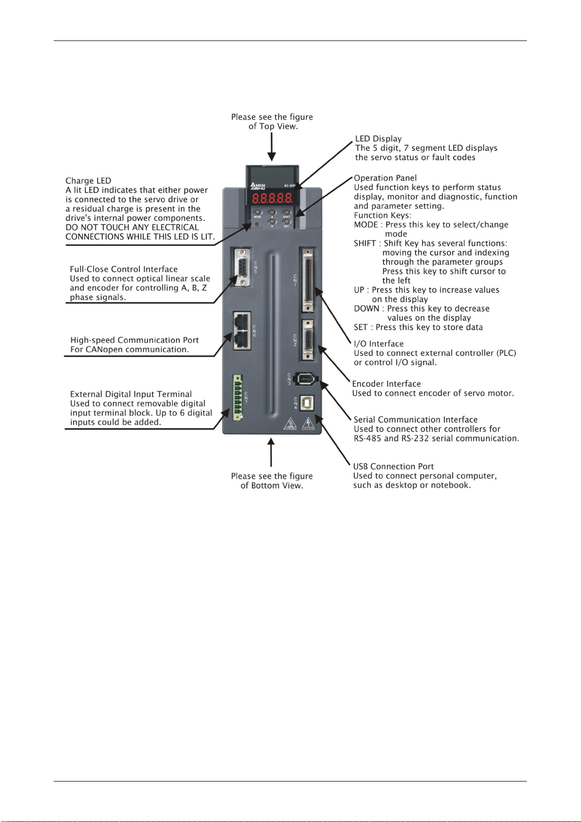
1.4 Each Part of the Servo Drive ................................................................................... 1-9
1.4.1 220 V Series ...................................................................................................... 1-9
1.4.2 400 V Series ...................................................................................................... 1-12
Chapter 2 Installation ........................................................................................................... 2-1
2.1 Notes ....................................................................................................................... 2-1
2.2 Ambient Conditions of Storage ................................................................................ 2-1
2.3 Ambient Conditions of Installation ........................................................................... 2-1
2.4 Installation Direction and Space .............................................................................. 2-2
2.5 Specification of Circuit Breaker and Fuse ............................................................... 2-5
2.6 EMI Filter Selection ................................................................................................. 2-6
2.7 Selection of Regenerative Resistor ......................................................................... 2-9
Chapter 3 Wiring ................................................................................................................... 3-1
3.1 Connections – 220V series ..................................................................................... 3-1
3.1.1 Connecting to Peripheral Devices ..................................................................... 3-1
Revision February, 2017 v
Page 7

ASDA-A2 Table of Contents
3.1.2 Connectors and Terminals of Servo Drive ......................................................... 3-2
3.1.3 Wiring Method ................................................................................................... 3-4
3.1.4 Specification of Motor Power Cable .................................................................. 3-6
3.1.5 Specification of Encoder Cable Connector ........................................................ 3-8
3.1.6 Selection of Wiring Rod ..................................................................................... 3-12
3.2 Connections – 400V series ..................................................................................... 3-14
3.2.1 Connecting to Peripheral Devices ..................................................................... 3-14
3.2.2 Connectors and Terminals of the Servo Drive ................................................... 3-16
3.2.3 Wiring Method ................................................................................................... 3-18
3.2.4 Specification of Motor Power Cable .................................................................. 3-19
3.2.5 Specification of Encoder Connector .................................................................. 3-21
3.2.6 Selection of Wiring Rod ..................................................................................... 3-23
3.3 Basic Wiring ............................................................................................................ 3-25
3.3.1 220V series ....................................................................................................... 3-25
3.3.2 400V series ....................................................................................................... 3-28
3.4 I/O Signal (CN1) Connection ................................................................................... 3-30
3.4.1 I/O Signal (CN1) Connector Terminal Layout .................................................... 3-30
3.4.2 Signals Explanation of Connector CN1 ............................................................. 3-32
3.4.3 Wiring Diagrams (CN1) ..................................................................................... 3-42
3.4.4 DI and DO Signal Specified by Users................................................................ 3-50
3.4.5 Application: Using CN1 Quick Connector for Wiring ......................................... 3-50
3.5 CN2 Connector ........................................................................................................ 3-54
3.6 Wiring of CN3 Connector ........................................................................................ 3-57
3.6.1 Layout of CN3 Connector .................................................................................. 3-57
3.6.2 Connection between PC and Connector CN3 ................................................... 3-58
vi Revision February, 2017
Page 8

Table of Contents ASDA-A2
3.7 CN4 Serial Connector (USB) ................................................................................... 3-59
3.8 CN5 Connector (Full-closed loop) ........................................................................... 3-60
3.9 CN6 Connector (CANopen) ..................................................................................... 3-61
3.10 Extension Digital Input Connector of CN7 ............................................................... 3-63
3.11 CN8 Connector of Battery Box ................................................................................ 3-64
3.12 Standard Connection Example – 220V series ......................................................... 3-65
3.12.1 Position (PT) Control Mode ............................................................................... 3-65
3.12.2 Position (PR) Control Mode ............................................................................... 3-66
3.12.3 Speed Control Mode ......................................................................................... 3-67
3.12.4 Torque Control Mode ........................................................................................ 3-68
3.12.5 Communication Mode ....................................................................................... 3-69
3.13 Standard Connection Example – 400V series ......................................................... 3-70
3.13.1 Position (PT) Control Mode ............................................................................... 3-70
3.13.2 Position (PR) Control Mode ............................................................................... 3-71
3.13.3 Speed Control Mode ......................................................................................... 3-72
3.13.4 Torque Control Mode ........................................................................................ 3-73
3.13.5 Communication Mode ....................................................................................... 3-74
Chapter 4 Panel Display and Operation .............................................................................. 4-1
4.1 Panel Description .................................................................................................... 4-1
4.2 Parameter Setting Procedure .................................................................................. 4-2
4.3 Status Display ......................................................................................................... 4-5
4.3.1 Save Setting Display ......................................................................................... 4-5
4.3.2 Decimal Point .................................................................................................... 4-5
4.3.3 Alarm Message ................................................................................................. 4-5
4.3.4 Positive and Negative Sign Setting .................................................................. 4-5
Revision February, 2017 vii
Page 9

ASDA-A2 Table of Contents
4.3.5 Monitor Display .................................................................................................. 4-6
4.4 General Function ..................................................................................................... 4-9
4.4.1 Operation of Fault Record Display .................................................................... 4-9
4.4.2 JOG Mode ......................................................................................................... 4-10
4.4.3 Force DO Output ............................................................................................... 4-11
4.4.4 Digital Input Diagnosis Operation ...................................................................... 4-12
4.4.5 Digital Output Diagnosis Operation ................................................................... 4-12
Chapter 5 Trial Operation and Tuning ................................................................................ 5-1
5.1 Inspection without Load ........................................................................................... 5-1
5.2 Applying Power to the Servo Drive .......................................................................... 5-2
5.3 JOG Trial Run without Load .................................................................................... 5-6
5.4 Trial Run without Load (Speed Mode) ..................................................................... 5-7
5.5 Trial Run without Load (Position Mode) .................................................................. 5-9
5.6 Tuning Procedure .................................................................................................... 5-11
5.6.1 Flowchart of Tuning Procedure ......................................................................... 5-12
5.6.2 Inertia Estimation Flowchart (with Mechanism) ................................................. 5-13
5.6.3 Flowchart of Auto Tuning .................................................................................. 5-14
5.6.4 Flowchart of Semi-Auto Tuning ......................................................................... 5-15
5.6.5 Limit of Inertia Ratio .......................................................................................... 5-16
5.6.6 Mechanical Resonance Suppression Method ................................................... 5-18
5.6.7 Tuning Mode and Parameters ........................................................................... 5-19
5.6.8 Tuning in Manual Mode ..................................................................................... 5-20
Chapter 6 Control Mode of Operation ................................................................................. 6-1
6.1 Selection of Operation Mode ................................................................................... 6-1
6.2 Position Mode .......................................................................................................... 6-3
viii Revision February, 2017
Page 10

Table of Contents ASDA-A2
6.2.1 Position Command in PT Mode ......................................................................... 6-3
6.2.2 Position Command in PR Mode ........................................................................ 6-7
6.2.3 Control Structure of Position Mode.................................................................... 6-8
6.2.4 S-curve Filter (Position) ..................................................................................... 6-9
6.2.5 Electronic Gear Ratio ........................................................................................ 6-12
6.2.6 Low-pass Filter .................................................................................................. 6-15
6.2.7 Timing Diagram in Position Mode (PR) ............................................................. 6-16
6.2.8 Gain Adjustment of Position Loop ..................................................................... 6-17
6.2.9 Low-frequency Vibration Suppression in Position Mode ................................... 6-19
6.3 Speed Mode ............................................................................................................ 6-24
6.3.1 Selection of Speed Mode .................................................................................. 6-24
6.3.2 Control Structure of Speed Mode ...................................................................... 6-25
6.3.3 Smooth Speed Command ................................................................................. 6-26
6.3.4 The Scaling of Analog Command ...................................................................... 6-30
6.3.5 Timing Diagram in Speed Mode ........................................................................ 6-31
6.3.6 Gain Adjustment of Speed Loop ....................................................................... 6-31
6.3.7 Resonance Suppression ................................................................................... 6-38
6.4 Torque Mode ........................................................................................................... 6-45
6.4.1 Selection of Torque Command .......................................................................... 6-45
6.4.2 Control Structure of Torque Mode ..................................................................... 6-46
6.4.3 Smooth Torque Command ................................................................................ 6-47
6.4.4 The Scaling of Analog Command ...................................................................... 6-47
6.4.5 Timing Diagram in Torque Mode ....................................................................... 6-48
6.5 Dual Mode ............................................................................................................... 6-49
6.5.1 Speed / Position Dual Mode .............................................................................. 6-50
Revision February, 2017 ix
Page 11

ASDA-A2 Table of Contents
6.5.2 Speed / Torque Dual Mode ............................................................................... 6-50
6.5.3 Torque / Position Dual Mode ............................................................................. 6-51
6.6 Others ...................................................................................................................... 6-52
6.6.1 The Use of Speed Limit ..................................................................................... 6-52
6.6.2 The Use of Torque Limit .................................................................................... 6-52
6.6.3 Analog Monitor .................................................................................................. 6-53
6.6.4 The Use of Brake .............................................................................................. 6-57
Chapter 7 Motion Control ..................................................................................................... 7-1
7.1 Motion Control Functions of ASDA-A2 .................................................................... 7-1
7.2 System Information ................................................................................................. 7-1
7.2.1 Description of Monitoring Variables ................................................................... 7-2
7.2.2 Description of Data Array .................................................................................. 7-8
7.3 Description of Motion Axes ...................................................................................... 7-11
7.4 Description of PR Mode .......................................................................................... 7-12
7.5 The Difference between General PR Mode and the One in ASDA-A2 ................... 7-12
7.6 The Position Unit of PR Mode ................................................................................. 7-13
7.7 Description of Register in PR Mode ........................................................................ 7-13
7.8 Homing Description of PR Mode ............................................................................. 7-15
7.9 DI/DO Provided by PR Mode and Diagrams ........................................................... 7-16
7.10 Parameter Settings .................................................................................................. 7-18
7.10.1 The Relation between the Previous Path and the Next Path ............................ 7-25
7.10.2 Programming the Path in PR Mode ................................................................... 7-26
7.11 The Description of E-Cam Function ........................................................................ 7-27
7.11.1 Function Description of CAPTURE (Data Capture) ........................................... 7-34
7.11.2 Function Description of COMPARE (Data Compare) ........................................ 7-36
x Revision February, 2017
Page 12

Table of Contents ASDA-A2
Chapter 8 Parameters ........................................................................................................... 8-1
8.1 Parameter Definition ............................................................................................... 8-1
8.2 List of Parameters .................................................................................................. 8-2
8.3 Parameter Description ........................................................................................... 8-13
P0-xx Monitor Parameters .......................................................................................... 8-13
P1-xx Basic Parameters ............................................................................................. 8-40
P2-xx Extension Parameters ....................................................................................... 8-91
P3-xx Communication Parameters ............................................................................. 8-136
P4-xx Diagnosis Parameters ...................................................................................... 8-147
P5-xx Motion Setting Parameters ............................................................................... 8-161
P6-xx PR Parameters ................................................................................................. 8-225
P7-xx PR Parameters ................................................................................................. 8-267
Table 8.1 Function Description of Digital Input (DI) ..................................................... 8-279
Table 8.2 Function Description of Digital Output (DO) ................................................. 8-288
Chapter 9 Communications ................................................................................................. 9-1
9.1 RS-485 & RS-232 Communication Hardware Interface .......................................... 9-1
9.2 RS-485 & RS-232 Communication Parameters Setting .......................................... 9-3
9.3 MODBUS Communication Protocol ........................................................................ 9-6
9.4 Write-in and Read-out Communication Parameters ................................................ 9-18
Chapter 10 Troubleshooting .............................................................................................. 10-1
10.1 Alarm of Servo Drive ............................................................................................. 10-1
10.2 Alarm of CANopen Communication ...................................................................... 10-5
10.3 Alarm of Motion Control ......................................................................................... 10-7
10.4 Causes and Corrective Actions ............................................................................. 10-10
10.5 Corrective Actions after the Alarm Occurs ............................................................ 10-29
Revision February, 2017 xi
Page 13

ASDA-A2 Table of Contents
Chapter 11 Specifications .................................................................................................. 11-1
11.1 Specifications of Servo Drives ................................................................................. 11-1
11.1.1 ASDA-A2 220V Series ..................................................................................... 11-1
11.1.2 ASDA-A2 400V Series ..................................................................................... 11-4
11.2 Specifications of Servo Motors (ECMA Series) ....................................................... 11-7
11.2.1 ECMA 220V Series.......................................................................................... 11-7
11.2.2 ECMA 400V Series........................................................................................ 11-17
11.3 Torque Features (T-N Curves) .............................................................................. 11-25
11.3.1 220V Series ................................................................................................... 11-25
11.3.2 400V Series ................................................................................................... 11-27
11.4 Overload Features ................................................................................................. 11-29
11.5 Dimensions of Servo Drive .................................................................................... 11-31
11.5.1 220V Series ................................................................................................... 11-31
11.5.2 400V Series ................................................................................................... 11-38
11.6 Dimensions of Servo Motor (ECMA Series) .......................................................... 11-41
11.6.1 220V Series ................................................................................................... 11-41
11.6.2 400V Series ................................................................................................... 11-48
Chapter 12 Absolute System ............................................................................................. 12-1
12.1 Backup Battery Boxes ............................................................................................. 12-2
12.1.1 Specifications .................................................................................................. 12-2
12.1.2 Battery Box Dimensions .................................................................................. 12-4
12.1.3 Connection Cables for Absolute Encoder ........................................................ 12-5
12.1.4 Battery Box Cords ........................................................................................... 12-7
12.2 Installation ............................................................................................................... 12-8
12.2.1 Connection Examples ...................................................................................... 12-8
xii Revision February, 2017
Page 14

Table of Contents ASDA-A2
12.2.2 How to Install a Battery .................................................................................. 12-12
12.2.3 How to Replace a Battery .............................................................................. 12-13
12.3 System Initialization Procedure and Operation ..................................................... 12-15
12.3.1 System Initialization Procedure ..................................................................... 12-15
12.3.2 Pulse Counting .............................................................................................. 12-16
12.3.3 PUU Counting................................................................................................ 12-17
12.3.4 Use Digital Inputs/Outputs to Initialize an Absolute System .......................... 12-18
12.3.5 Use Parameters to Initialize an Absolute System .......................................... 12-18
12.3.6 Use Digital Inputs/Outputs to Read the Absolute Coordinate Data ............... 12-19
12.3.7 Use Parameter to Read the Absolute Coordinate Data ................................. 12-23
12.4 Related Parameters for Absolute System ............................................................. 12-24
12.5 Digital Input (DI) Function Definition (for Absolute System) .................................. 12-30
12.6 Digital Output (DO) Function Definition (for Absolute System) ............................. 12-31
12.7 Alarms for Absolute System .................................................................................. 12-32
12.7.1 Causes and Corrective Actions ..................................................................... 12-33
12.8 Related Monitoring Variables ................................................................................ 12-35
Appendix A Accessories ..................................................................................................... A-1
Appendix B Maintenance and Inspection .......................................................................... B-1
Revision February, 2017 xiii
Page 15

ASDA-A2 Table of Contents
About this Manual
User Information
Be sure to store this manual in a safe place.
Due to constantly growing product range, technical improvement and alteration or changed texts,
figures and diagrams, we reserve the right of this manual contained information change without
prior notice.
Coping or reproducing any part of this manual, without written consent of Delta Electronics Inc. is
prohibited.
Technical Support and Service
Welcome to contact us or visit our web site if you need any technical
support, service and information, or, if you have any question in using the product. We are looking
forward to serve you ne
the following ways.
eds and willing to offer our best support and service to you. Reach us by
xiv Revision February, 2017
Page 16

Chapter 1 Inspection and Model
Explanation
1.1 Inspection
In order to prevent the negligence during purchasing and delivery, please inspect the following
items carefully.
Please check if the product is what you have purchased: check the part number of the
motor and the servo drive on the nameplate. Refer to the next page for the model
explanation.
Check if the motor shaft can rotate smoothly: Rotate the motor shaft by hand. If it can be
rotated smoothly, it means the motor shaft is normal. However, it cannot be rotated by hand
if the motor has an electromagnetic brake.
Check if there is any damage shown on its appearance: visually check if there is any
damage or scrape of the appearance.
Check if there is any loose screw: If the screws are un-tightened or fall off.
If any of the above situations happens, please contact the distributors to solve the problems.
A complete and workable servo set should include:
(1) A Servo drive and a servo motor
(2) A UVW motor power cable, the U, V and W wires can connect to the socket attached by
the servo drive and another side is the plug which could connect to the socket of the
motor. And a green ground wire which should be locked to the ground terminal of the
servo drive. (selective purchase)
(3) An encoder cable which connects to the socket of the encoder. One side of it connects to
CN2 servo drive and another side is the plug. (selective purchase)
(4) 50-PIN connector which is used in CN1 (selective purchase)
(5) 20-PIN connector which is used in CN2 (selective purchase)
(6) 6-PIN connector which is used in CN3 and is for general communication (RS-485)
(selective purchase)
(7) 4-PIN connector which used in CN4 (USB Type B product) (selective purchase)
(8) RJ45 connector which used in CN6 and is for high-speed communication (selective
purchase)
(9) 7-PIN connector which used in CN7, for extension DI. (-U model) (selective purchase)
Revision February, 2017 1-1
Page 17
ASDA-A2
(10) Servo drive power input:
220V:
Control circuit power Main circuit power
Chapter 1 Inspection and Model Explanation
100 W ~ 3 kW
405 kW ~ 15 kW
L1c, L2C, fast connector
L1c, L2C, terminal block
R, S, T fast connector
R, S, T terminal block
400V:
Control circuit power Main circuit power
750 W ~ 1.5 kW
2 kW ~ 7.5 kW
DC24V, DC0V, fast connector
DC24V, DC0V, terminal block
R, S, T fast connector
R, S, T terminal block
(11) 3-PIN fast connector (U, V, W)
(12) 3-PIN fast connector (P , D, C)
(13) A plastic lever (for 220V 100 W ~ 3 kW and 400V 750 W ~ 1.5 kW)
(14) A metal short-circuit chip (for 220 V 100 W ~ 4.5 kW and 400 V 750 W ~ 1.5 kW)
(15) An installation manual
1-2 Revision February, 2017
Page 18
Chapter 1 Inspection and Model Explanation ASDA-A2
1.2 Product Model
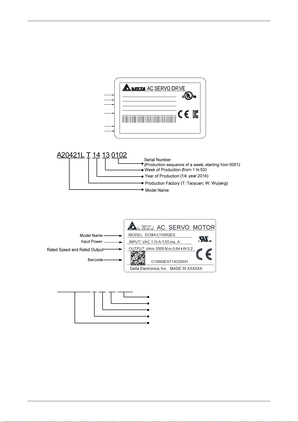
1.2.1 Nameplate Information
ASDA-A2 Series Servo Drive
Nameplate Information
Capacity Specification
Model Name
Applicable power Supply
Rated Current Output
Barcode
Firmware Version
Serial Number
ECMA Series Servo Motor
Nameplate Information
MODEL : ASD-A2-0421-L
POWER : 400W
INPUT : 200~230V 3PH 50/60Hz 1.86A
200~230V 1PH 50/60Hz 3.22A
OUTPUT : 110V 0-250Hz 2.6A
A20421LT14130102
01.34
DELTA ELECTRONICS, INC.
LISTED
19XK
IND. CONT. EQ.
MADE IN TAIWAN
Serial Number
C10602ES T 14 33 0001
Serial Number
(Production sequence of a week, starting from 0001)
Week of Production (from 1 to 52)
Year of Production (14: year 2014)
Production Factory (T: Taoyuan; W: Wujiang)
Model Name
Revision February, 2017 1-3
Page 19

ASDA-A2
p
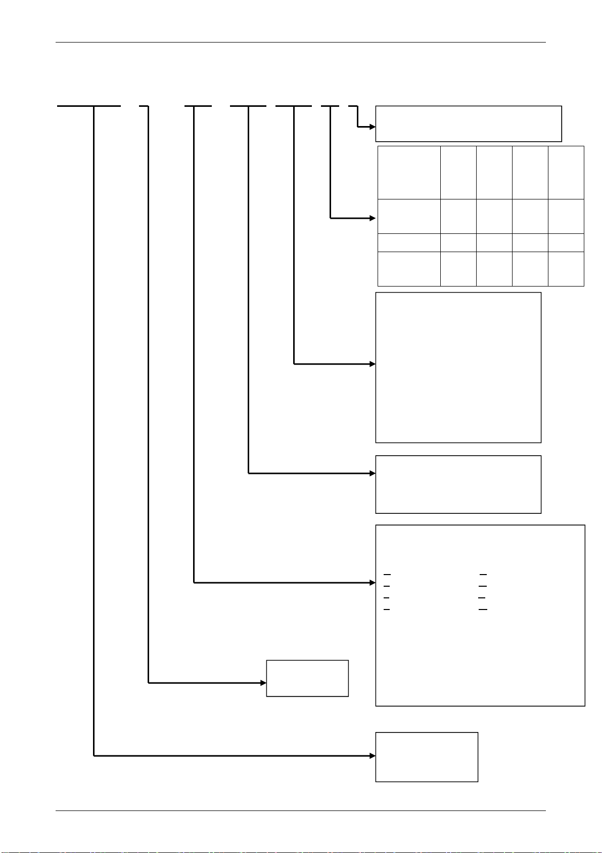
1.2.2 Model Explanation
ASDA-A2 Series Servo Drive
ASD-A2-0743-U
Chapter 1 Inspection and Model Explanation
Model Type
Input Voltage and Phase
21: 220V 1 phase
23: 220V 3 phase
43: 400V 3
Rate Output Power
01: 100W 20: 2kW
02: 200W 30: 3kW
04: 400W 45: 4.5kW
07: 750W 55: 5.5kW
10: 1kW 75: 7.5kW
15: 1.5kW 1B: 11kW
1F: 15kW
Series
A2
hase
Model Type
Type RS-485
(CN3)
Standard
Model
Network
Model
L O O X X X X O O O X
U O O O X X X O O O O
E X O O O X X X X O O
F O O X X X O X X O X
M O O X X O X O O O O
Full-closed
control
(CN5)*1
Extension
Port for
Digital
Input
(CN7)
EtherCAT CANopen DMCNET Analog
NOTE
1. In PR mode, only A2-F supports full-closed control function.
2. PR parameters can be read and written through communication by DMCNET only.
3. E-cam function can only be used in PR mode.
Product Name
AC SERVO Drive
Voltage
Control
Pulse
Input
Port
PR
Mode*2
E-Cam*3
1-4 Revision February, 2017
Page 20
Chapter 1 Inspection and Model Explanation ASDA-A2
A: A
ECMA Series Servo Motor
ECMA-C10602ES
Standard Shaft Diameter: S
Specific Shaft Diameter: 3=42mm, 7=14mm
Type of Shaft
Diameter and
Oil Seal
Round Shaft
(with fixed
screw holes)
Keyway
Keyway (with
fixed screw
holes)
w/o
Brake,
w/o Oil
Seal
with
Brake,
w/o Oil
Seal
- - C D
E F - -
P Q R S
w/o
Brake,
with
Oil
Seal
Rated Power Output
0F:50W 09:900W 50:5.0kW
01:100W 10:1.0kW 55:5.5kW
02:200W 13:1.3kW 75:7.5kW
03:300W 15:1.5kW 1B:11kW
04:400W 18:1.8kW 1F:15kW
05:500W 20:2.0kW
06:600W 30:3.0kW
07:750W 35:3.5kW
08:850W 45:4.5kW
With
Brake,
with
Oil
Seal
Servo Type
C Servo
Motor Frame Size
04:40mm 09:86mm 18:180mm
06:60mm 10:100mm 22:220mm
08:80mm 13:130mm
Name of the Series
Rated Voltage and Rated Speed
C = 220V/3,000 rpm; E = 220V/2,000 rpm;
F = 220V/1,500 rpm; G = 220V/1,000 rpm;
J = 400V/3,000 rpm; K = 400V/2,000 rpm;
L = 400V/1,500 rpm; M = 400V/1,000 rpm
Encoder Type
1: Incremental, 20-bit
2: Incremental, 17-bit
3: 2500 ppr
A: Absolute (Resolution of single cycle: 17-
bit; Resolution of multi-cycle: 16-bit)
Product Name
ECM: Electronic
Commutation Motor
Revision February, 2017 1-5
Page 21
ASDA-A2
Chapter 1 Inspection and Model Explanation
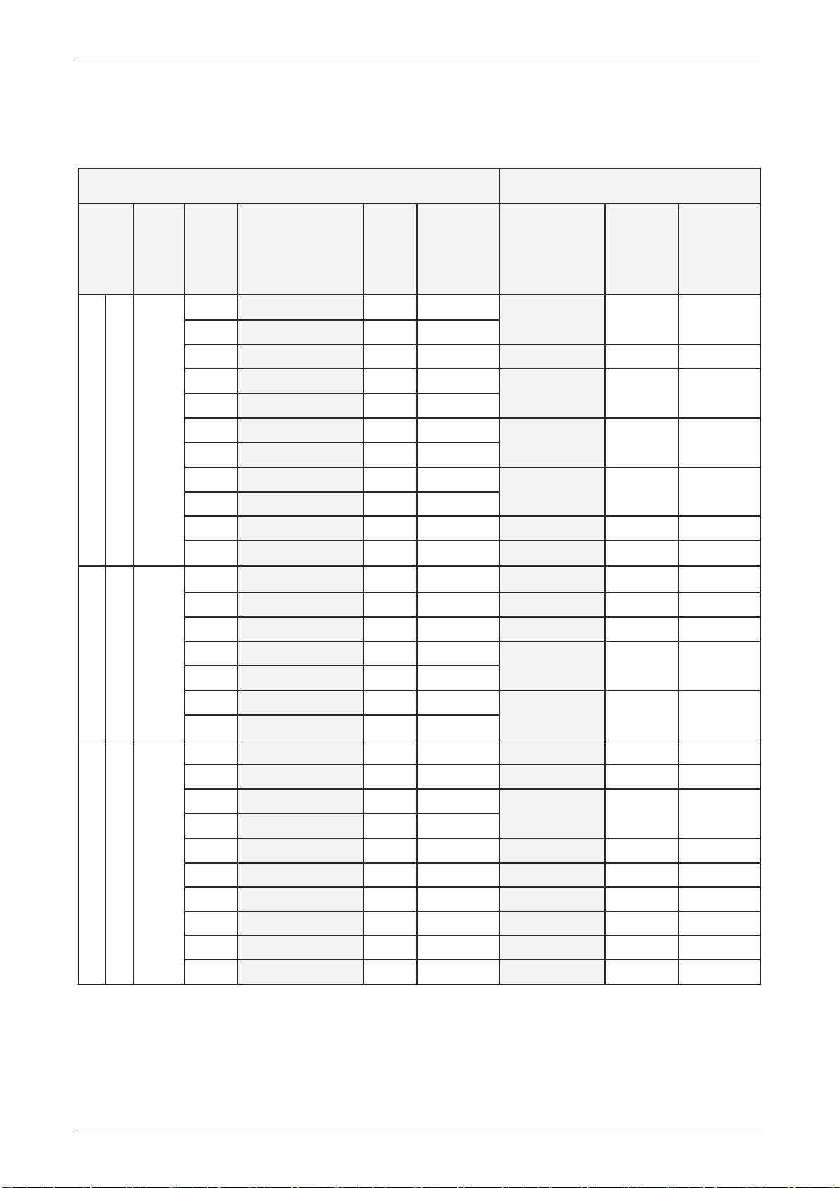
1.3 Servo Drive and Corresponding Servo Motor
1.3.1 220V Series
Motor Servo Drive
Motor
series
Low Inertia
Medium Inertia
ECMA-C 3000 r/min
ECMA-E 2000 r/min
Power
Single/Three-
phase
Single/Three-
phase
Output
(W)
50
100
200
400
400
750
750
1000
1000
2000
3000
500
1000
1500
2000
2000
3000
3500
Model Number
ECMA-C1040F□S 0.69 2.05
ECMA-C△0401□S
ECMA-C△0602□S
ECMA-C△0604□S
ECMA-C△0804□7
ECMA-C△0807□S
ECMA-C△0907□S
ECMA-C△0910□S
ECMA-C△1010□S
ECMA-C△1020□S
ECMA-C△1330□4
ECMA-E△1305□S
ECMA-E△1310□S
ECMA-E△1315□S
ECMA-E△1320□S
ECMA-E△1820□S
ECMA-E△1830□S
ECMA-E△1835□S
Rated
Current
(Arms)
0.90 2.70
1.55 4.65
2.60 7.80
2.60 7.80
5.10 15.30
3.66 11.00
4.25 12.37
7.30 21.90
12.05 36.15
17.2 47.5
2.90 8.70
5.60 16.80
8.30 24.90
11.01 33.03
11.22 33.66
16.10 48.30
19.20 57.60
Max.
Instantaneous
current
(A)
Continuous
Model Number
ASD-A2-0121-□ 0.90 2.70
ASD-A2-0221-□ 1.55 4.65
ASD-A2-0421-□ 2.60 7.80
ASD-A2-0721-□ 5.10 15.30
ASD-A2-1021-□ 7.30 21.90
ASD-A2-2023-□ 13.40 40.20
ASD-A2-3023-□ 19.40 58.20
ASD-A2-0421-□ 2.60 7.80
ASD-A2-1021-□ 7.30 21.90
ASD-A2-1521-□ 8.30 24.90
ASD-A2-2023-□ 13.40 40.20
ASD-A2-3023-□ 19.40 58.20
Output
Current
(Arms)
Max.
Instantaneous
output current
(A)
ECMA-F△1305□S
ECMA-F△1308□S
ECMA-F△1313□S
ECMA-F△1318□S
ECMA-F△1830□S
ECMA-F△1845□S
3.90 12.10
7.10 19.40
12.60 38.60
13.00 36.00
19.40 58.20
32.50 81.30
ASD-A2-0721-□ 5.10 15.30
ASD-A2-1021-□ 7.30 21.90
ASD-A2-2023-□ 13.40 40.20
ASD-A2-3023-□ 19.40 58.20
ASD-A2-4523-□ 32.50 - -
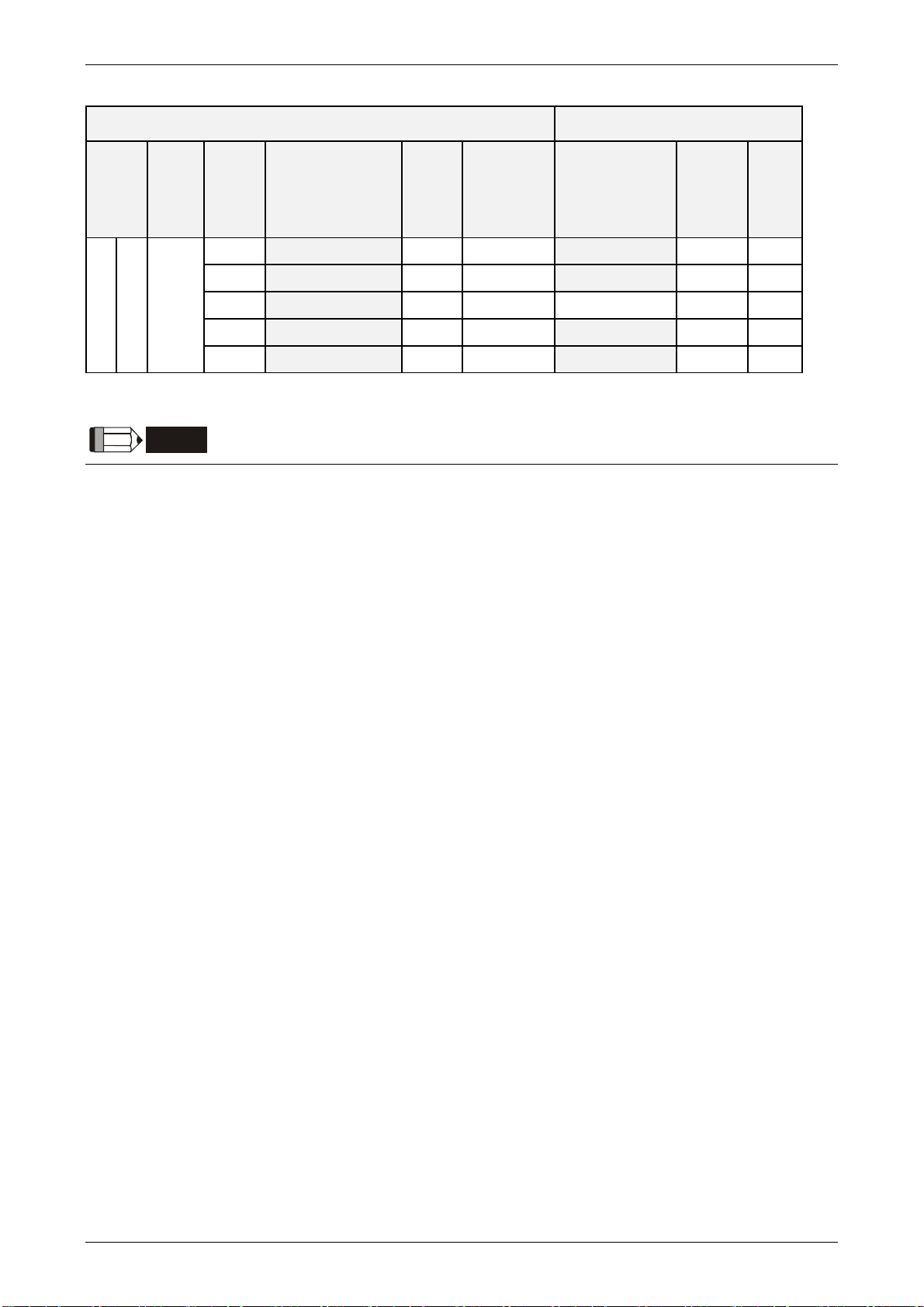
Medium-high inertia
ECMA-F 1500 r/min
Single/Three-
phase
500
850
1300
1800
3000
4500
5500 ECMA-△F 1855□3 40.00 100.00 ASD-A2-5523-□ 40.00 - -
7500 ECMA-△F 1875□3 47.50 118.80 ASD-A2-7523-□ 47.50 - -
11000 ECMA-F1221B□3 51.80 129.50 ASD-A2-1B23-□ 54.40 - -
15000 ECMA-F1221F□S 61.50 145.70 ASD-A2-1F23-□ 70.00 - -
1-6 Revision February, 2017
Page 22
Chapter 1 Inspection and Model Explanation ASDA-A2
Motor Servo Drive
Max.
Instanta
neous
output
current
(A)
Motor
series
High Inertia
Power
Single-
/Three-
phase
ECMA-C/G 3000 r/min
Output
(W)
400
750
300
600
900
Model Number
ECMA-C△0604□H
ECMA-C△0807□H
ECMA-G△1303□S
ECMA-G△1306□S
ECMA-G△1309□S
Rated
Current
(Arms)
2.60 7.80
5.10 15.30
2.50 7.50 ASD-A2-0421-□ 2.60 7.80
4.80 14.40
7.50 22.50
Max.
Instantaneous
current
(A)
Model Number
ASD-A2-0421-□ 2.60 7.80
ASD-A2-0721-□ 5.10 15.30
ASD-A2-0721-□ 5.10 15.30
ASD-A2-1021-□ 7.30 21.90
Continuou
s Output
Current
(Arms)
NOTE
1. The boxes () at the ends of the servo drive model names are for optional configurations. For the actual
model name, please refer to the ordering information of the actual purchased product.
2. The boxes (
2: Incremental type, 17-bit;
information searching, please contact to your local distributors for actual purchased product.
△
) in the model names are for encoder resolution types. △= 1: Incremental type, 20-bit; △=
△= 3: 2500 ppr; △= A: Absolute type). The listed motor model name is for
3. The boxes () in the model names represents brake or keyway oil seal.
4 *11kw and 15kW will be available soon.
The above table shows the specification of servo drive which has triple rated current. For detailed
specification of the servo motor and servo drive, please refer to Chapter 11.
Revision February, 2017 1-7
Page 23
ASDA-A2
1.3.2 400V Series
Chapter 1 Inspection and Model Explanation
Motor Servo Drive
Motor
series
Low Inertia
Medium Inertia
Medium-high Inertia
ECMA-J 3000 r/min
ECMA-K 2000 r/min
ECMA-L 1500 r/min
Power
Three-
phase
Three-
phase
Three-
phase
Output
(W)
400
750
750
1000
1000
2000
3000
750
1000
1500
2000
2000
750
850
1300
3000
4500
5500
7500
Model Number
ECMA-Jᇞ0604 S
ECMA-Jᇞ0807 S
ECMA-Jᇞ0907 S
ECMA-Jᇞ0910 S
ECMA-Jᇞ1010 S
ECMA-Jᇞ1020 S
ECMA-Jᇞ1330 4
ECMA-Kᇞ1305 S
ECMA-Kᇞ1310 S
ECMA-Kᇞ1315 S
ECMA-Kᇞ1320 S
ECMA-Kᇞ1820 S
ECMA-Lᇞ1305 S
ECMA-Lᇞ1308 S
ECMA-Lᇞ1313 S
ECMA-Lᇞ1830 S
ECMA-Lᇞ1845 S
ECMA-Lᇞ1855 3
ECMA-Lᇞ1875 3
Rated
Current
(Arms)
1.62 4.85
3.07 9.5
2.16 6.37
2.4 7.17
4.15 12.46
7.09 21.28
9.8 29.99
1.7 5.2
3.52 10.56
5.02 15.06
6.66 19.98
6.6 19.88
2.1 6.1
3.4 8.85
5.02 15
11.53 34.6
20.8 52
22.37 56
27.3 68.3
Max.
Instantaneous
current
(A)
Continuous
Model Number
ASD-A2-0743-□ 3.07 9.21
ASD-A2-0743-□ 3.07 9.21
ASD-A2-0743-□ 3.07 9.21
ASD-A2-1043-□ 3.52 9.86
ASD-A2-1543-□ 5.02 10.04
ASD-A2-2043-□ 6.66 18.65
ASD-A2-3043-□ 11.9 33.32
ASD-A2-0743-□ 3.07 9.21
ASD-A2-1043-□ 3.52 9.86
ASD-A2-1543-□ 5.02 10.04
ASD-A2-2043-□ 6.66 18.65
ASD-A2-2043-□ 6.66 18.65
ASD-A2-0743-□ 3.07 9.21
ASD-A2-1043-□ 3.52 9.86
ASD-A2-1543-□ 5.02 10.04
ASD-A2-3043-□ 11.9 33.32
ASD-A2-4543-□ 20 44
ASD-A2-5543-□ 22.04 48.49
ASD-A2-7543-□ 28.39 62.46
Output
Current
(Arms)
Max.
Instantaneous
output current
(A)
3000 r/min
High Inertia
Three-
phase
ECMA-G 1000
900
ECMA-Mᇞ1309 S
4.4 13.1
ASD-A2-1543-□ 5.02 10.04
NOTE
1. The boxes () at the ends of the servo drive model names are for optional configurations. For the actual
model name, please refer to the ordering information of the actual purchased product.
2. The boxes (
2: Incremental type, 17-bit;
information searching, please contact to your local distributors for actual purchased product.
3. The boxes () in the model names represents brake or keyway oil seal.
The above table shows the specification of servo drive which has triple rated current. For detailed
specification of the servo motor and servo drive, please refer to Chapter 11.
△
) in the model names are for encoder resolution types. △= 1: Incremental type, 20-bit; △=
△= 3: 2500 ppr; △= A: Absolute type). The listed motor model name is for
1-8 Revision February, 2017
Page 24
Chapter 1 Inspection and Model Explanation ASDA-A2
1.4 Each Part of the Servo Drive
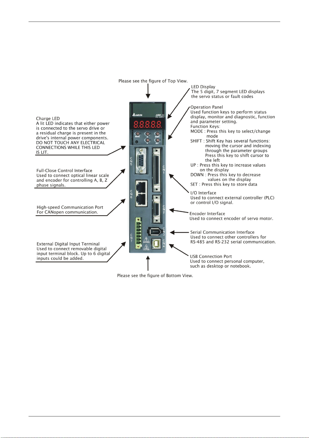
1.4.1 220V Series
220V Series - Front View
Revision February, 2017 1-9
Page 25
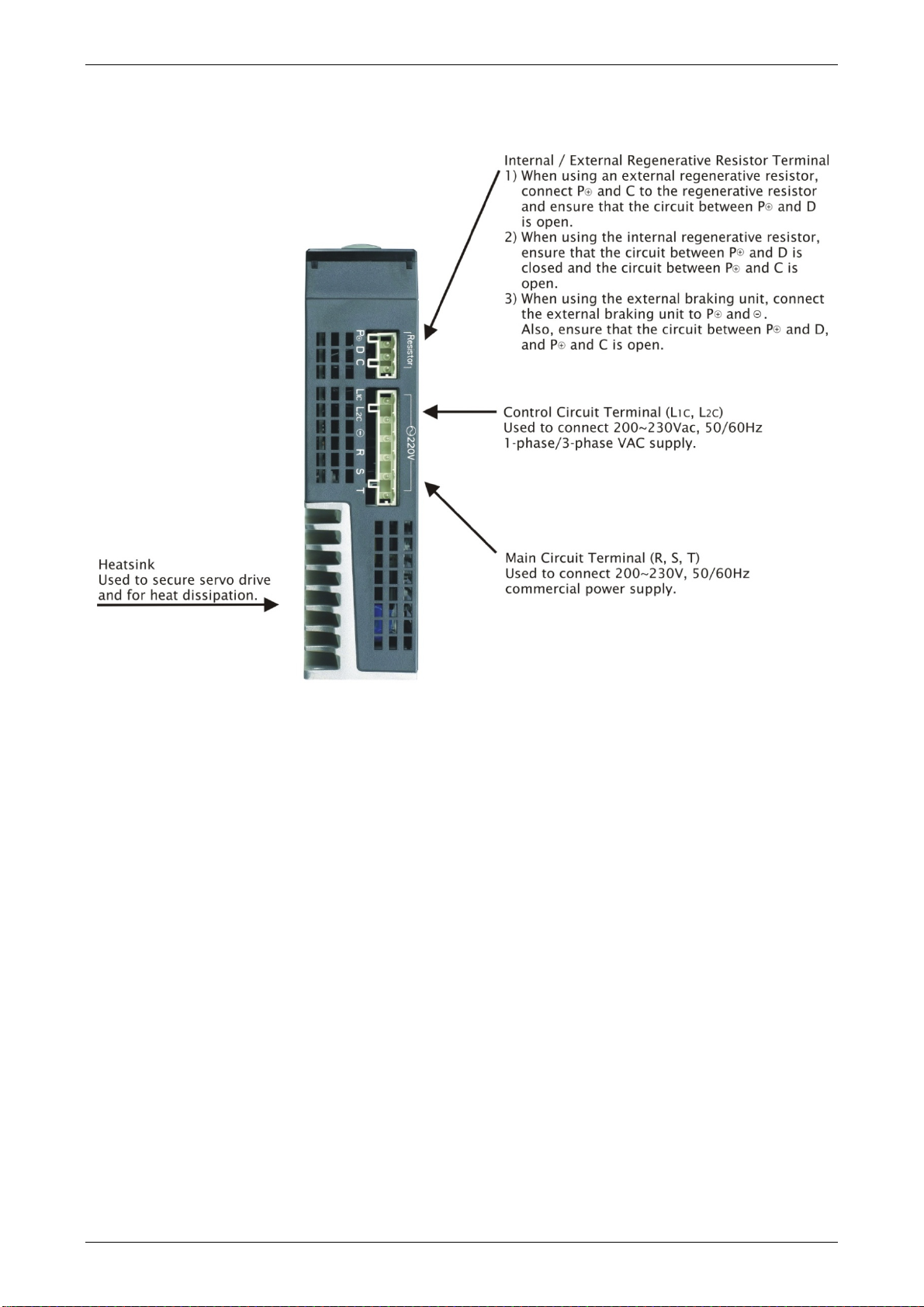
ASDA-A2
220V Series - Top View
Chapter 1 Inspection and Model Explanation
1-10 Revision February, 2017
Page 26
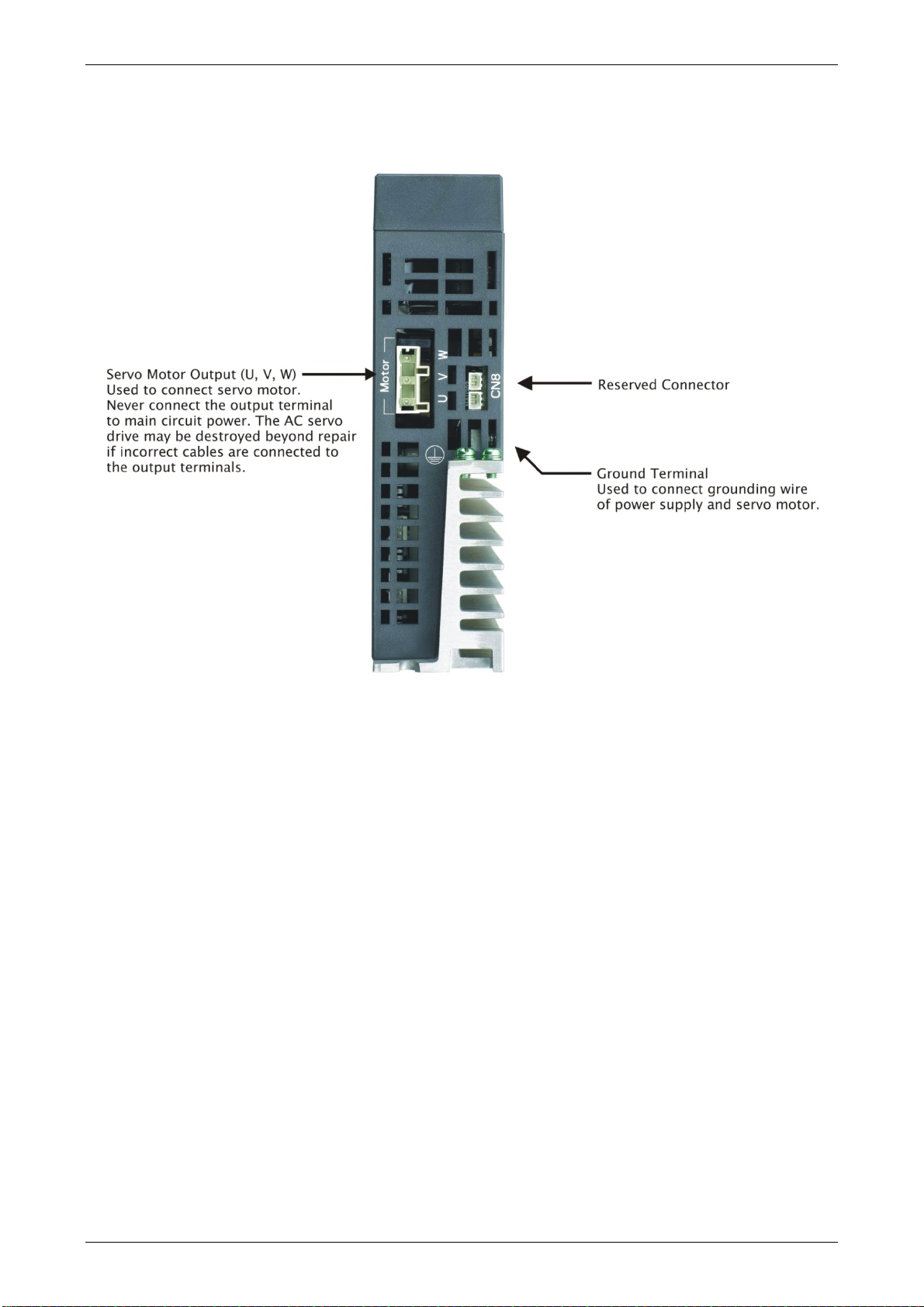
Chapter 1 Inspection and Model Explanation ASDA-A2
220V Series - Bottom View
Revision February, 2017 1-11
Page 27
ASDA-A2
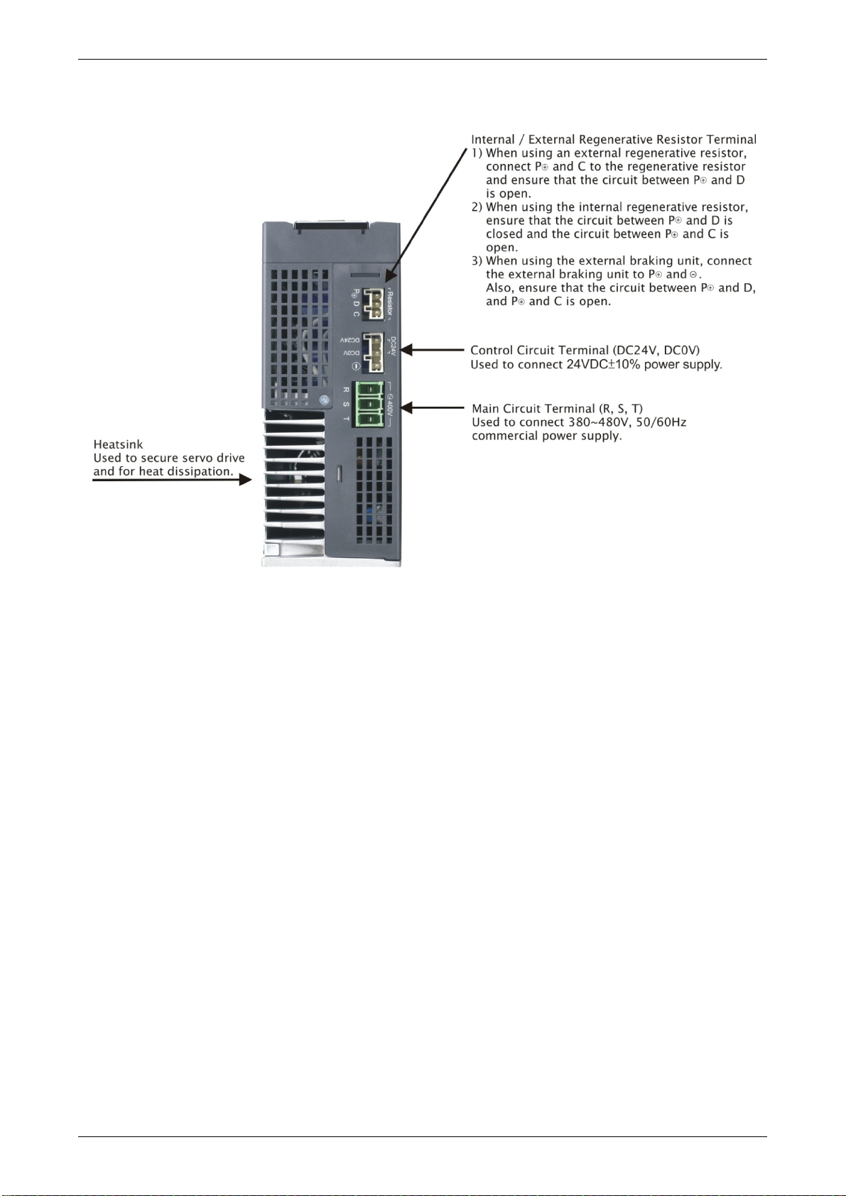
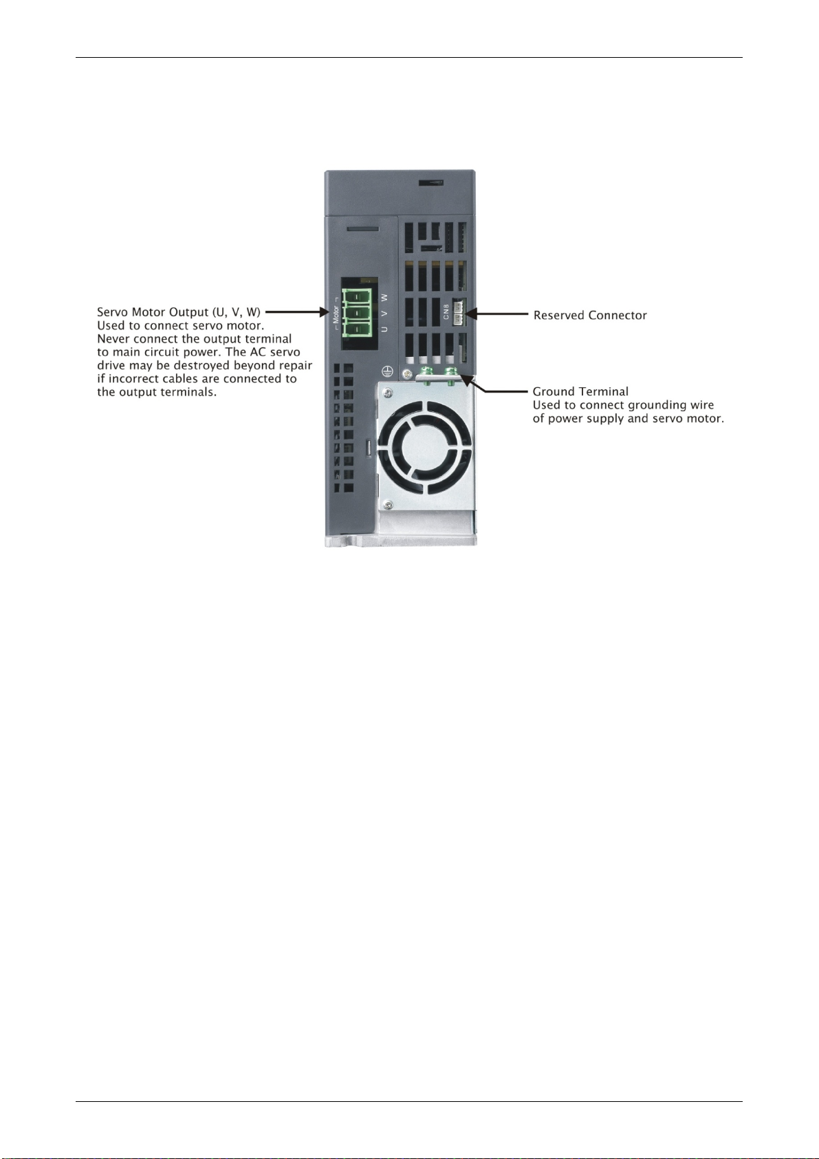
1.4.2 400V Series
400V Series - Front View
Chapter 1 Inspection and Model Explanation
1-12 Revision February, 2017
Page 28
Chapter 1 Inspection and Model Explanation ASDA-A2
400V Series - Top View
Revision February, 2017 1-13
Page 29
ASDA-A2
400V Series - Bottom View
Chapter 1 Inspection and Model Explanation
1-14 Revision February, 2017
Page 30

Chapter 2 Installation
2.1 Notes
Please pay special attention to the followings:
If the connection between the servo drive and the servo motor is over 20 meters, please
thicken the connecting wire, UVW as well as the encoder cable. Please refer to section 3.1.6
for further information.
2.2 Ambient Conditions of Storage
Before the installation, this product has to be kept in shipping carton. In order to retain the warranty
coverage and for the maintenance, please follow the instructions below when storage, if the
product is not in use temporally:
Store the product within an ambient temperature range of -20 ℃ to +65 ℃.
Store the product within a relative humidity range of 0% to 90% and a non-condensing
environment.
Avoid storing the product in the environment of corrosive gas and liquid.
2.3 Ambient Conditions of Installation
The ambient conditions of installing and operating the servo drive:
Location has no over-heat device, no water drop, vapor, dust and oily dust, no corrosive and
inflammable gas and liquid, no airborne dust and metal particles, no interference of
electromagnetic noise and has solid foundation and no vibration.
The ambient conditions of operating the servo motor:
The ambient temperature is between 0 ℃ and 40 ℃. And the ambient location shall has no overheat device, no water drop, vapor, dust and oily dust, no corrosive and inflammable gas and liquid,
no airborne dust and metal particles.
The best temperature of this servo drive is between 0 ℃ and 55 ℃. If the temperature is over 45 ℃,
please place the product in a well-ventilated environment so as to ensure its reliability performance.
If the product is installed in an electric box, make sure the size of the electric box and its ventilation
condition will not overheat and endanger the internal electronic device. Also, pay attention to the
vibration of the machine. Check if the vibration will influence the electronic device of the electric
box.
Revision February, 2017 2-1
Page 31

ASDA-A2 Chapter 2 Installation
2.4 Installation Direction and Space
Notes:
Incorrect installation may result in a drive malfunction or premature failure of the drive and
motor.
The ASDA-A2 servo drive should be mounted perpendicular to the wall or in the control panel.
In order to ensure the drive is well ventilated, ensure that the all ventilation holes are not
obstructed and sufficient free space is given to the servo drive. Do not install the drive in a
horizontal position or malfunction and damage will occur.
Do not parallel connect the servo drive, or it might burn out the soft-start resistance or the
commutator and danger will occur.
2-2 Revision February, 2017
Page 32

Chapter 2 Installation ASDA-A2
Scheme of Installation:
In order to have smaller wind resistance of the fan and increase the ventilation, please follow the
suggested clearance value when installing one or more than one servo drives. (Refer to the
following diagrams)
NOTE
Revision February, 2017 2-3
The above diagrams are not in equal proportion. Please refer to the
annotation.
Page 33

ASDA-A2 Chapter 2 Installation
NOTE
2-4 Revision February, 2017
The above diagrams are not in equal proportion. Please refer to the
annotation.
Page 34

Chapter 2 Installation ASDA-A2
2.5 Specification of Circuit Breaker and Fuse
220V Series
Caution: Please use the fuse and circuit breaker that is recognized by UL/CSA.
Servo Drive Model Circuit Breaker Fuse (Class T)
Operation Mode General General
ASD-A2-0121- 5A 5A
ASD-A2-0221- 5A 5A
ASD-A2-0421- 10A 10A
ASD-A2-0721- 10A 20A
ASD-A2-1021- 15A 25A
ASD-A2-1521- 20A 40A
ASD-A2-2023- 30A 50A
ASD-A2-3023- 30A 70A
ASD-A2-4523- 70A 140A
ASD-A2-5523- 75A 150A
ASD-A2-7523- 95A 175A
ASD-A2-1B23- - -
ASD-A2-1F23- - -
If the servo drive equips with earth leakage circuit breaker for avoiding electric
NOTE
leakage, please choose the current sensitivity which is over 200 mA and can
continue up to 0.1 seconds.
400V Series
Caution: Please use the fuse and circuit breaker that is recognized by UL/CSA.
Servo Drive Model Circuit Breaker Fuse (Class T)
Operation Mode General General
ASD-A2-0743- 10A 20A
ASD-A2-1043- 15A 25A
ASD-A2-1543- 20A 40A
ASD-A2-2043- 30A 50A
ASD-A2-3043- 30A 70A
ASD-A2-4543- 70A 140A
ASD-A2-5543- 75A 150A
ASD-A2-7543- 95A 175A
If the servo drive equips with earth leakage circuit breaker for avoiding electric
NOTE
Revision February, 2017 2-5
leakage, please choose the current sensitivity which is over 200 mA and can
continue up to 0.1 seconds.
Page 35

ASDA-A2 Chapter 2 Installation
2.6 EMI Filter Selection
220V Series
Recommended EMI Filter
Item Power Servo Drive Model
1PH 3PH
1 100W ASD-A2-0121- RF007S21AA RF022B43AA N
2 200W ASD-A2-0221- RF007S21AA RF022B43AA N
3 400W ASD-A2-0421- RF007S21AA RF022B43AA N
4 750W ASD-A2-0721- RF007S21AA RF037B43BA N
5 1.0kW ASD-A2-1021- RF007S21AA RF037B43BA N
6 1.5kW ASD-A2-1521- RF007S21AA RF037B43BA N
7 2.0kW ASD-A2-2023- - RF037B43BA N
8 3.0kW ASD-A2-3023- - RF037B43BA N
9 4.5kW ASD-A2-4523- - RF075M43BA N
FootPrint
10 5.5kW ASD-A2-5523- - RF075M43BA Y
11 7.5kW ASD-A2-7523- - 30TDRT1W4 Y
12 11.0kW ASD-A2-1B23- - 50TDS4W4C -
13 15.0kW ASD-A2-1F23- - 50TDS4W4C -
400V Series
Item Power Servo Drive Model Recommended EMI Filter FootPrint
1 750W ASD-A2-0743- RF007S43AA N
2 1000W ASD-A2-1043- RF007S43AA N
3 1500W ASD-A2-1543- RF022B43AA N
4 2000W ASD-A2-2043- RF037B43BA N
5 3000W ASD-A2-3043- RF037B43BA N
6 4500W ASD-A2-4543- RF075M43BA N
7 5500W ASD-A2-5543- RF075M43BA Y
8 7500W ASD-A2-7543- RF075M43BA Y
2-6 Revision February, 2017
Page 36

Chapter 2 Installation ASDA-A2
EMI Filter Installation
All electronic equipment (including servo drive) generates high or low frequency noise during
operation and interfere the peripheral equipments via conduction or radiation. With EMI Filter and
the correct installation, much interference can be eliminated. It is suggested to use Delta’s EMI
Filter to suppress the interference better.
When installing servo drive and EMI Filter, please follow the instructions of the user manual and
make sure it meets the following specification:
1. EN61000-6-4 (2001)
2. EN61800-3 (2004) PDS of category C2
3. EN55011+A2 (2007) Class A Group 1
General Precaution
In order to ensure the best performance of EMI Filter, apart from the instructions of servo drive
installation and wiring, please follow the precautions mention below:
1. The servo drive and EMI Filter should be installed on the same metal plate.
2. When installing servo drive and EMI Filter, the servo drive should be installed above the EMI
Filter.
3. The wiring should be as short as possible.
4. The metal plate should be well grounded.
5. The metal cover of the servo drive and EMI Filter or grounding should be firmly fixed on the
metal plate. Also, the contact area should be as large as possible.
Revision February, 2017 2-7
Page 37

ASDA-A2 Chapter 2 Installation
Motor Cable Selection and Installation Precautions
The selection of motor cables and installation affect the performance of EMI Filter. Please follow
the precautions mention below.
1. Use the cable that has braid shielding (The effect of double shielding is better)
2. The shield on both sides of the motor cable should be grounded in the shortest distance and
the largest contact area.
3. The protective paint of the U-shape saddle and metal plate should be removed in order to
ensure the good contact. Please see figure 1.
4. It should have correct connection between the braid shielding of the motor cable and the
metal plate. The braid shielding on both sides of the motor cable should be fixed by the Ushape saddle and metal plate. Please see figure 2 for the correct connection.
Saddle on both ends
Figure 1
Saddle on one end
Figure 2
2-8 Revision February, 2017
Page 38

Chapter 2 Installation ASDA-A2
2.7 Selection of Regenerative Resistor
When the direction of pull-out torque is different from the rotation, it means the electricity is sent
back to the servo drive from the load-end. It becomes the capacitance of DC Bus and increases
the voltage. When the voltage increases to a specific value, the come-back eletricity can only be
consumed by regenerative resistor. There is a built-in regenerative resistor in the servo drive.
Users can also use the external regenerative resistor if needed.
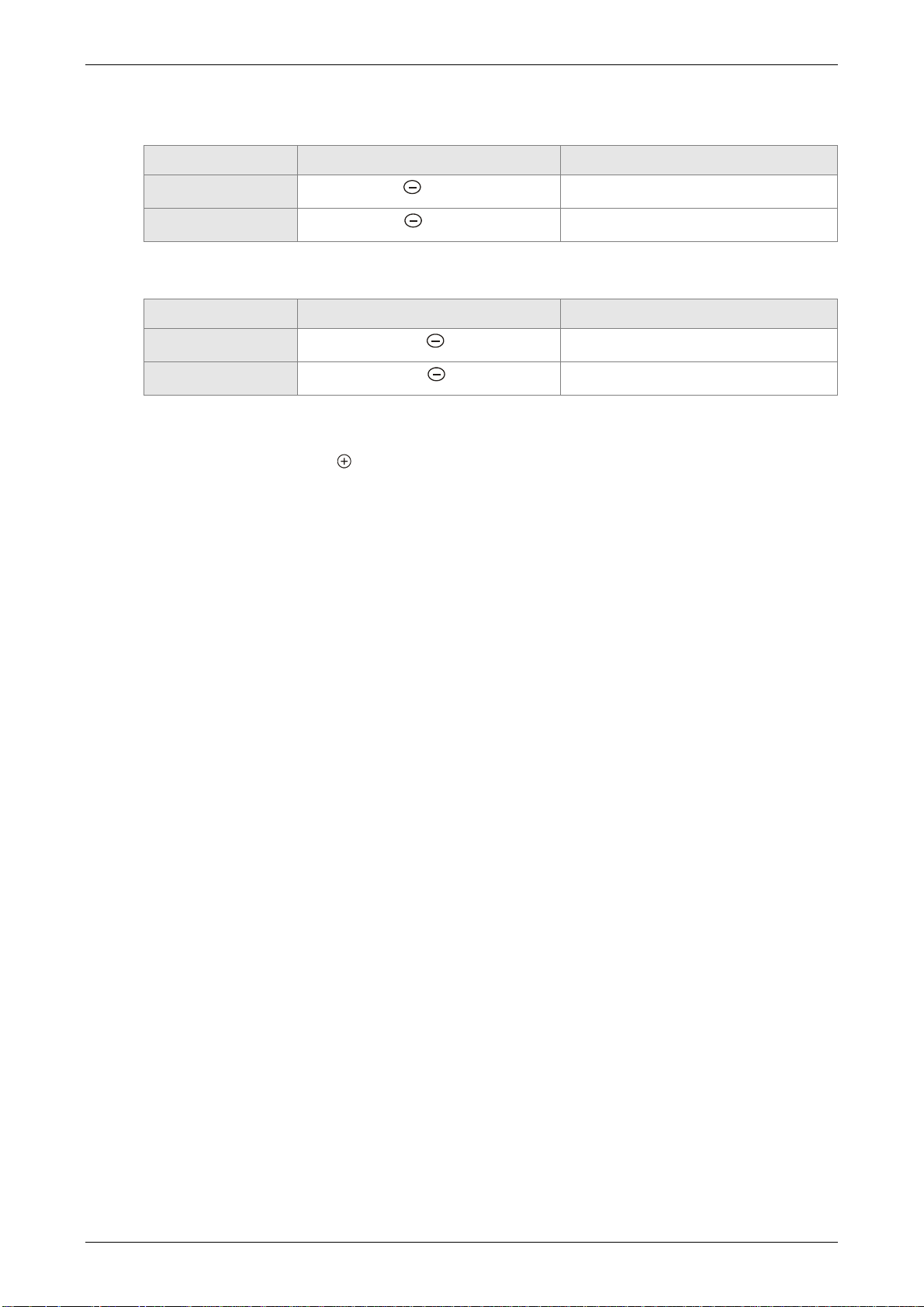
Specification of built-in regenerative resistor provided by ASDA-A2 220V Series
Servo Drive
(kW)
Specification of built-in regenerative
resistor
Resistance
(P1-52) (Ohm)
Capacity
(P1-53) (Watt)
*1The capacity of built-
in regenerative resistor
(Watt)
Minimum allowable
resistance (Ohm)
0.1 - - - 30
0.2
0.4
- - - 30
40 40 20 30
0.75 40 60 30 20
1.0 40 60 30 20
1.5 40 60 30 20
2.0 20 100 50 10
3.0 20 100 50 10
4.5 20 100 50 10
5.5 - - - 8
7.5 - - - 5
11 - - - 8
15 - - - 5
Specification of built-in regenerative resistor provided by ASDA-A2 400V Series
Specification of built-in regenerative
Servo Drive
(kW)
Resistance
(P1-52) (Ohm)
resistor
(P1-53) (Watt)
Capacity
Minimum allowable
resistance (Ohm)
0.75 80 100 60
1.0 80 100 60
1.5 80 100 40
2.0 - - 40
3.0 - - 30
4.5 - - 20
5.5 - - 20
7.5 - - 15
Revision February, 2017 2-9
Page 39

ASDA-A2 Chapter 2 Installation
When the regenerative resistor exceeds the capacity of built-in regenerative resistor, the external
regenerative resistor should be applied. Please pay special attention to the followings when using
the regenerative resistor.
1. Please correctly set up the resistance (P1-52) and capacity (P1-53) of regenerative resistor.
Or it might influence the performance of this function.
2. If users desire to use the external regenerative resistor, please make sure the applied value
should not smaller than the built-in regenerative resistor. In general application, more than
one resistor will be serial connected. If the value (from serial connected resistors) exceeds
the setting range, users can reduce the value by parallel connecting the resistor. If users
desire to connect it in parallel to increase the power of regenerative resistor, please make
sure the capacitance meets the requirements.
Please refer to the followings for the calculation when serial / parallel connecting regenerative
resistors:
Setting:
P1-52=10 (Ω)
P1-53=1000 (W)
Setting:
P1-52=20 (Ω)
P1-53=2000 (W)
Setting:
P1-52=5 (Ω)
P1-53=2000 (W)
3. In natural environment, if the capacity of regenerative resistor (the average value) is within
the rated capacity, the temperature of the capacitance will increase to 120℃ or even higher
(under the condition of regenerative energy keeps existing). For safety concerns, please
apply the method of forced cooling in order to reduce the temperature of regenerative
resistor. Or, it is suggested to use the regenerative resistor which is equipped with thermal
switches. Please contact the distributors for load characteristics of the regenerative resistor.
When using the external regenerative resistor, the resistor should connect to P, C terminal and the
contact of P, D terminal should be opened. It is recommended to choose the above mentioned
capacitance. For easy calculation of regenerative resistor capacity, except the energy consumed
by IGBT, two ways are provided to select the capacity of external regenerative resistor according
to the selected linear motor or rotary motor.
2-10 Revision February, 2017
Page 40

Chapter 2 Installation ASDA-A2
(1) Regenerative Power Selection
(a) When the external load on torque does not exist
If the motor operates back and forth, the energy generated by the brake will go into the
capacitance of DC bus. When the voltage of the capacitance exceeds a specific value, the
redundant energy will be consumed by regenerative resistor. Two ways of selecting
regenerative resistor are provided here. The table below provides the energy calculation
method. Users can refer to it and calculate the selected regenerative resistor.
220V
Servo Drive
(kW)
0.1
0.1
0.2
0.4
Low
Inertia
0.4
0.75
1.0
1.0
2.0
3.0
0.4
Motor
ECMA-C△040F
ECMA-C△0401
ECMA-C△0602
ECMA-C△0604
ECMA-C△0804
ECMA-C△0807
ECMA-C△1010
ECMC-C△0910
ECMA-C△1020
ECMA-C△1330
ECMA-E△1305
The maximum
regenerative power of
capacitance
Ec (joule)
Rotor Inertia
J (× 10-
4kg.m2)
Regenerative power
from empty load
3000r/min to stop
Eo (joule)
0.021 0.10 4.21
0.037 0.18 4.21
0.177 0.87 5.62
0.277 1.37 8.42
0.68 3.36 8.42
1.13 5.59 17.47
2.65 13.10 21.22
2.62 12.96 21.22
4.45 22.0 25.58
12.7 62.80 25.58
8.17 40.40 8.42
Medium
Inertia
Medium
–High
Inertia
ECMA-E△1310
1.0
ECMA-E△1315
1.5
ECMA-E△1320
2.0
ECMA-E△1820
2.0
ECMA-E△1830
3.0
ECMA-E△1835
3.0
ECMA-F△1308
1.0
ECMA-F△1313
2.0
ECMA-F△1318
2.0
ECMA-F△1830
3.0
ECMA-F△1845
4.5
ECMA-F△1855
5.5
ECMA-F△1875
7.5
8.41 41.59 21.22
11.18 55.29 25.58
14.59 72.15 25.58
34.68 171.49 25.58
54.95 271.73 31.20
54.95 271.73 31.20
13.6 67.25 21.22
20.0 98.90 25.58
24.9 123.13 31.20
54.95 271.73 28
77.75 384.48 25
99.78 493.42 27
142.7 705.66 93
Revision February, 2017 2-11
Page 41

ASDA-A2 Chapter 2 Installation
Servo Drive
(kW)
Medium
11.0
ECMA- F△221B
Motor
–High
ECMA- F△221F
Inertia
High
Inertia
15.0
ECMA-G△1303
0.4
ECMA-F△1305
0.75
ECMA-G△1306
0.75
ECMA-G△1309
1.0
Eo= J * wr2/182 (joule), Wr: r/min
400V
Servo Drive
(kW)
Motor
The maximum
regenerative power of
capacitance
Ec (joule)
Rotor Inertia
J (× 10-
4kg.m2)
Regenerative power
from empty load
3000r/min to stop
Eo (joule)
329.0 723.08 117
553.0 1215.38
156
8.17 17.96 8.42
10.3 22.64 17.47
8.41 18.48 17.47
11.18 24.57 21.22
The maximum
regenerative power
of capacitance
Ec (joule)
Rotor Inertia
J (× 10-
4kg.m2)
Regenerative power
from empty load
3000r/min to stop
Eo (joule)
Low
Inertia
Medium
Inertia
ECMA-J△0604
0.75
ECMA-J△0807
0.75
ECMA-J△0907
0.75
ECMA-J△1010
1.0
ECMA-J△1010
1.5
ECMA-J
2.0
ECMA-K△1305
0.75
ECMA-K△1310
1.0
ECMA-K△1315
1.5
ECMA-K△1320
2.0
ECMA-K△1820
2.0
△1020
0.277 1.37 42.43
1.13 5.59 42.43
1.93 9.54 42.46
2.65 13.10 42.43
2.65 13.10 42.43
4.45 22.01 42.43
8.17 40.40 51.17
8.41 41.59 51.17
11.18 55.29 57.41
14.59 72.15 34.94
34.68 171.49 34.94
2-12 Revision February, 2017
Page 42

Chapter 2 Installation ASDA-A2
Servo Drive
(kW)
0.75
1.5
3.0
ECMA-L△1305
ECMA-L△1313
ECMA-L△1830
Motor
Medium
–High
Inertia
High
Inertia
3.0
4.5
5.5
7.5
1.0
1.5
ECMA-J△1330
ECMA-L△1845
ECMA-L△1855
ECMA-L△1875
ECMA-L△1308
ECMA-M△1309
Eo= J * wr2/182 (joule), Wr: r/min
The maximum
regenerative power of
capacitance
Ec (joule)
Rotor Inertia
J (× 10-
4kg.m2)
Regenerative power
from empty load
3000r/min to stop
Eo (joule)
13.1 16.20 42.43
23.6 29.18 42.43
54.95 67.93 42.43
12.7 15.70 42.43
77.75 96.12 51.17
99.78 123.35 57.41
142.7 176.41 62.40
17.1 84.56 42.43
11.18 55.29 57.41
Assume that the load inertia is N times to the motor inertia and the motor decelerates from
3000r/min to 0, its regenerative energy is (N+1) x Eo. The consumed regenerative resistor is (N+1)
× Eo - Ec joule. If the cycle of back and forth operation is T sec, then the power of regenerative
resistor it needs is 2× ((N+1) x Eo - Ec) / T.
Followings are the calculation procedure:
Steps Item Calculation and Setting Method
1
2
Set the capacity of regenerative
resistor to the maximum
Set T cycle of back and forth
operation
Set P1-53 to the maximum value
Enter by the user
3 Set the rotational speed wr Enter by the user or read via P0-02
4 Set the load/motor inertia ratio N Enter by the user or read via P0-02
Calculate the maximum regenerative
5
6
7
Set the absorbable regenerative
Calculate the needful capacitance of
energy Eo
energy Ec
regenerative resistor
Eo= J * wr2/182
Refer to the above table
2 x ((N+1) x Eo – Ec) / T
Revision February, 2017 2-13
Page 43

ASDA-A2 Chapter 2 Installation
Take 400W as the example, the cycle of back and forth operation is T = 0.4sec, the maximum
speed is 3000r/min and the load inertia is 7 times to the motor inertia. Then, the needful power of
regenerative resistor is 2 × ((7+1) × 1.68 – 8) / 0.4 = 27.2 W. If it is smaller than the built-in capacity
of regenerative resistor, the built-in 60W regenerative resistor will do. Generally speaking, when
the need of the external load inertia is not much, the built-in regenerative is enough. The diagram
below describes the actual operation. The smaller power of the regenerative resistor it is, the more
energy it accumulates and the higher temperature it will be. When the temperature is higher than a
specific value, ALE05 occurs.
(b) If the external load torque exists, the motor is in reverse rotation.
Usually, the motor is in forward rotation, which means the torque output direction of the motor
is the same as the rotation direction. However, in some applications, the direction of torque
output is different from the rotation. In this situation, the motor is in reverse rotation. The
external energy goes into the servo drive through the motor. The diagram below is one
example. When the external force direction is the same as the moving direction, the servo
system has to use the force of the opposite direction to keep the speed and stability. Huge
amount of energy will return to the servo drive at the moment. When DC-BUS is full and
unable to store the regenerative energy, the energy will be leaded to regenerative resistor
and consumed.
馬達轉速
Motor Speed
External Load Torque
外部負載扭矩
Motor Output Torque
馬達輸出扭矩
馬達輸出負功 正功 負功
Negative Torque
Torque
Negative Torque Positive
正功
Positive
Negative torque: TL × Wr TL: external load torque
For safety reasons, please calculate it by considering the safest situation.
For example, when the external load torque is the +70% rated torque and the rotation
reaches 3000 r/min, then take 400 W (the rated torque is 1.27 Nt-m) as the example, the
user has to connect the regenerative resistor of 40, which is 2 × (0.7× 1.27) × (3000 × 2 × π/
60) = 560W.
2-14 Revision February, 2017
Page 44

Chapter 2 Installation ASDA-A2
(2) Simple Selection
Choose the appropriate regenerative resistor according to the allowable frequency and
empty load frequency in actual operation. The so-called empty allowable frequency is the
frequency of continuous operation when the servo motor runs from 0r/min to the rated speed
and then decelerates from the rated speed to 0r/min within the shortest time. The following
table lists the allowable frequency when the servo drive runs without load (times/min).
Allowable frequency when the servo motor runs without load (times/min)
and uses a built-in regenerative resistor
1.0
1.5
kW
2.0
kW
83
(F100)
24
(F130)
Motor Capacity
Servo Motor
600W 750W 900W
kW
06 07 09 10 15 20 20 30 45 55 75 1B 1F
ECMAC - 312 - 137 -
ECMAE - - - 42 32
ECMAF - - - - - - - 11 8 - - - -
ECMAG 42 - 31 - - - - - - - - - -
ECMAJ - 537 - - - - - - - - - - -
ECMAK - - - 162 122 - - - - - - - -
ECMAL - - - - - - - - - - - - -
2.0
3.0
4.5
5.5
7.5
11.0
15.0
kW
kW
kW
kW
kW
kW
kW
- - - - - - -
10
(F180)
11 - - - - -
When the servo motor runs with load, the allowable frequency will be different according to
different load inertia or speed. The following is the calculation method.
m represents load / motor inertia ratio.
2
Allowable fr equency =
Allowable frequency when servo motor run without load
m + 1
Rated speed
x
Operating speed
The comparison table of external regenerative resistor is provided below. Please choose the
appropriate regenerative resistor according to the allowable frequency.
The table below describes the suggested allowable frequency (times/min) of regenerative
resistor when the servo drive runs without load.
Allowable frequency of regenerative resistor when the servo drive runs without load (times/min)
ECMAC
Motor Capacity
100W 200W
Corresponding Motor
01 02 04 04 07 10 20
BR400W040 (400W 40Ω) - - 8608 3506 2110 925 562
BR1K0W020 (1kW 20Ω) - - - 8765 5274 2312 1406
400W
(F60)
400W
(F80)
750W 1.0kW 2.0kW
times
min.
Revision February, 2017 2-15
Page 45

ASDA-A2 Chapter 2 Installation
ECMAE
Motor Capacity
0.5kW 1kW 1.5kw
Corresponding Motor
05 1.0 15 20 20 30
BR400W040 (400W 40Ω) 291 283 213 163 68 -
BR1K0W020 (1kW 20Ω) 729 708 533 408 171 -
BR1K5W005*2 (3kW 10Ω) - - - - - 331
2.0kW
(F130)
2.0kW
(F180)
3.0kW
ECMAF
Corresponding Motor
BR1K5W005*2 (3kW 10Ω) 331 234 182 127 124 74
Motor Capacity
3.0KW 4.5KW 5.5KW 7.5kW 11.0kW 15.0kW
30 45 55 75 1B 1F
Allowable frequency of regenerative resistor when the servo drive runs without load (times/min)
Motor Capacity
Corresponding Motor
BR400W040 (400W 40Ω) 292 283 213
BR1K0W020 (1kW 20Ω) 729 708 533
0.3kW 0.6kW 0.9kW
03 06 09
ECMAG
ECMAK
Motor Capacity
Corresponding Motor
BR400W040 (400W 40Ω) - 488 665
1.0kW 1.5kW 2.0kW
10 15 20
Motor Capacity
3.0KW 4.5KW 5.5KW 7.5kW
Corresponding Motor
BR400W040 (400W 40Ω) 177 - - -
BR1K0W020 (1kW 20Ω) - 312 243 170
30 45 55 75
ECMAL
If watt is not enough when using regenerative resistor, connecting the same regenerative
resistor in parallel can increase the power.
2-16 Revision February, 2017
Page 46

Chapter 2 Installation ASDA-A2
Dimensions of Regenerative Resistor
Delta Part Number:BR400W040 (400W 40Ω)
L1 L2 H D W MAX. WEIGHT (g)
265 250 30 5.3 60 930
Delta Part Number:BR1K0W020 (1kW 20Ω)
L1 L2 H D W MAX. WEIGHT (g)
400 385 50 5.3 100 2800
Revision February, 2017 2-17
Page 47

ASDA-A2 Chapter 2 Installation
Delta Part Number:BR1K5W005 (3kW 10Ω)
2-18 Revision February, 2017
Page 48

Chapter 3 Wiring
This chapter provides information on wiring ASDA-A2 series products, the descriptions of I/O
signals and gives typical examples of wiring diagrams.
3.1 Connections - 220V series
3.1.1 Connecting to Peripheral Devices
Power
100W~1.5kW Single-/Three-phase 200~230V
2kW~15kW Three-phase 200~230V
No Fuse Breaker (NFB)
Installing a NFB can prevent excessive current may
arise due to short-circuit or flow when power on and
off, so as to avoid the damage on the servo drive
Elec trom agnetic
Cont act or (M C)
Rege nerative
Resistor (Option)
P
C
The returned regenerative power generated
when braking may result in damage. Thus,
external resistor is recommended. Connec t
the external resistor to P and C, and ensure
an open circuit between P and D. When
applying internal resistor, ensure t he c ircuit
is close between P and D, and the circuit is
open between P and C.
CN5 C onnec tor (Optio n)
For full-closed loop or linear scale c onnection
CN5: For ASDA-A2-L, -M, -U (Please refer to
the description of section 1.2.2)
CN6 C onnec tor (Optio n)
CN6: For ASDA-A2-M only (Please refer to the
description of section 1.2.2)
CN7 Connect or (Optio n)
CN7: For ASDA-A2-U only (Please refer to the
description of section 1.2.2)
P,D,C
L1c,L2c,Θ,R,S,T
Motor power
out put
Host Controller
It can connect to Delta PLC controller
or other brands of NC controllers.
CN1 I/O
Conn ector
CN2 C onnec tor
CN4 C onnec tor (Optio n)
1. Connect to personal computer via USB cable
2. Use ASDA-SOFT for tuning, parameter setting
and control.
Terminal Block Module (ASD-BM-50A)
(Option)
Transmit the signal from CN1
50pin to the controller via this
block module.
CN3 C onnector
(Option)
Use MODBUS
communication to support
RS-485/RS232
Servo Motor
Revision February, 2017 3-1
Page 49

Chapter 3 Wiring ASDA-A2
NOTE
Installation notes:
1. Check if the power and wiring among R, S, T and L1c, L2c are correct.
Please refer to Chapter 11 for Specifications. Make sure the input voltage
is correct, or it might damage the servo drive or danger may occur.
2. Please check if the output terminal U, V, W of the servo motor is correctly
wired. The incorrect wiring may disable the operation of the motor or cause
malfunction.
3. When applying to the external regenerative resistor, the contact between P
and D should be opened and the external regenerative resistor should
connect to terminal P and C. When applying to the internal regenerative
resistor, the contact between P and D should be closed and the contact
between P and C should be opened.
4. When an alarm occurs or the system is in emergency stop status, use
ALARM or WARN to output and disconnect the power of magnetic
contactor in order to disconnect the power of servo drive.
3.1.2 Connectors and Terminals of Servo Drive
Terminal
Signal
Name Description
L1c, L2c
R, S, T
U, V, W
FG
Power input of the control
circuit
Power input of the main
circuit
Motor cable
Connect to single-phase AC power (select the
appropriate voltage specification according to the
product )
Connect to three-phase AC power (select the
appropriate voltage specification according to the
product)
Connect to the servo motor
Terminal
Symbol
U Red
V White
W Black
Wire Color Description
Three-phase main
power cable of the
motor.
Connect to ground
FG Green
terminal (
) of the
servo drive.
The contact between P and D
Internal resistor
end should be closed; contact
between P and C end should
be opened.
Connect P , C ends to the resistor
P, D,
C,
Regenerative resistor
terminal or braking unit
External resistor
and the contact between P and D
end should be opened.
P and P of the brake unit
External braking
unit
should connect to P and P
respectively. The contact between
P and D and P and C should
be opened.
3-2 Revision February, 2017
Page 50

ASDA-A2 Chapter 3 Wiring
Connect to the ground wire of power and servo
motor.
Connect to the host controller. Please refer to
section 3.4.
Connect encoder of the motor. Please refer to
section 3.5.
Connect to RS-485 or RS-232. Please refer to
section 3.6.
Connect to personal computer (PC or notebook).
Please refer to section 3.7.
CN1
CN2
CN3
CN4
Ground terminal
I/O connector (Option)
Connector (Option)
Connector Option)
USB connector (Type B)
(Option)
Connect to linear scale or encoder for full-closed
CN5
Connector (Option)
loop and motor feedback. Please refer to section
3.8.
CN6
CN7
CN8
CANopen connector (Option) RJ45 connector. Please refer to section 3.9.
Extension digital input
connector (Option)
Extension DI connector. Please refer to section
3.10.
Battery connector Connector for absolute type of battery box
Pay special attention to the followings when wiring:
1. When the power is cutoff, do not touch R, S, T and U, V, W since the capacitance inside the
servo drive still contains huge amount of electric charge. Wait until the charging light is off.
2. Separate R, S, T and U, V, W from the other wires. The interval should be at least 30 cm
(11.8 inches).
3. If the wire of encoder CN2 or CN5 connecter is not long enough, please use shielded twisted-
pair cable which cannot exceed 20 meters (65.62 inches). If it exceeds 20 meters, please
choose the bigger wire diameter of signal cable to ensure it will not cause signal fading. As
for the encoder wiring specification of 20-meter-long cable, please use AWG26 of wire size
and metal braided shield twisted-pair cable which complies with the standard of UL 2464.
4. When using CANopen, please use the standard shielded twisted-pair cables to ensure the
communication quality.
5. When selecting the wire rod, please refer to Section 3.1.6.
6. Do not install the plug-in capacitance in servo drive. It might burn out the soft-start resistance
and danger will occur.
Revision February, 2017 3-3
Page 51

Chapter 3 Wiring ASDA-A2
3.1.3 Wiring Method
The wiring method of 220V servo drive is divided into single-phase and three-phase. In the
diagram below, Power On is contact a, Power Off and ALRM_RY are contact b. MC is the coil of
magnetic contactor and self-remaining power and is the contact of main power circuit.
Wiring Method of Single-phase Power Supply (suitable for 1.5 kW and models below 1.5
kW)
TR
Noise Filter
MC
MCCB
Power OnPower
MC
R
Off
Servo Drive
S
T
L1C
L2C
MC
SUP
ALRM_RY
CN1
DO5+(28)
DO5-(27)
W
U
V
Motor
DC24V
ALRM_RY
3-4 Revision February, 2017
Page 52

ASDA-A2 Chapter 3 Wiring
Wiring Method of Three-phase Power Supply (suitable for all series)
Revision February, 2017 3-5
Page 53

Chapter 3 Wiring ASDA-A2
3.1.4 Specification of Motor Power Cable
Motor Model U, V, W / Connector of Brake
ECMA-C1040FS (50W)
ECMA-C
ECMA-C
ECMA-C
ECMA-C
ECMA-C
ECMA-C
ECMA-C
ECMA-C
ECMA-C
△
0401S (100W)
△
0602S (200W)
△
0604S (400W)
△
0604H (400W)
△
08047 (400W)
△
0807S (750W)
△
0807H (750W)
△
0907S (750W)
△
0910S (1000W)
ECMA-C1040FS (50W)
△
ECMA-C
ECMA-C
ECMA-C
ECMA-C
ECMA-C
ECMA-C
ECMA-C
0401S (100W)
△
0602S (200W)
△
0604S (400W)
△
08047 (400W)
△
0807S (750W)
△
0907S (750W)
△
0910S (1000W)
* : with brake
Terminal
Definition
A
B
ECMA-G△1303S (300W)
ECMA-E
ECMA-F
ECMA-G
ECMA-F
ECMA-G
ECMA-C
ECMA-E
ECMA-F
ECMA-E
△
1305S (500W)
△
1305S (500W)
△
1306S (600W)
△
1308S (850W)
△
1309S (900W)
△
1010S (1000W)
△
1310S (1000W)
△
1313S (1300W)
△
1315S (1500W)
ECMA-F△1318S (1800W)
ECMA-C
ECMA-E
ECMA-C
△
1020S (2000W)
△
1320S (2000W)
△
13304 (3000W)
ECMA-E△1820S (2000W)
△
ECMA-E
ECMA-F
ECMA-E
ECMA-F
1830S (3000W)
△
1830S (3000W)
△
1835S (3500W)
△
1845S (4500W)
C
D
3-6
Revision February, 2017
Page 54

ASDA-A2 Chapter 3 Wiring
Motor Model U, V, W / Connector of Brake
ECMA-F△18553 (5500W)
△
ECMA-F
18753 (7500W)
ECMA-F1221B3 (11kW)
ECMA-F1221FS (15kW)
ECMA-F218553(5500W)
ECMA-F218753(7500W)
Wiring
Name
U
(Red) V (White) W (Black)
10SL-4S
AB
3106A-10SL-4S
CASE GROUND
(Green)
BRAKE1
(Yellow)
Terminal
Definition
E
F
BRAKE2
(Blue)
A 1 2 3 4 - -
B 1 2 4 5 3 6
C F I B E G H
D D E F G A B
E A B C D - -
Wiring Name BRAKE1 BRAKE2
F A B
When selecting the wire rod, please choose 600V PVC cable and the length should not longer than
30m. If the length exceeds 30m, please take the received voltage into consideration when
selecting the wire size. Please refer to Section 3.1.6 for wire rod selection.
NOTE
1) No polarity for brake coil, the wiring name is BRAKE1 & BRAKE2.
2) Power for brake is DC24 V. Never share it with the power of control signal VDD.
3) Box, (△) in servo motor model represents encoder type. △= 1: incremental, 20-bit; △= 2:
incremental, 17-bit; △ = 3: 33-bit; △= A: absolute.
4) Box, () in servo motor model represents brake or keyway / oil seal.
Revision February, 2017 3-7
Page 55

Chapter 3 Wiring ASDA-A2
3.1.5 Specification of Encoder Cable Connector
Encoder Connection (Diagram 1)
NOTE
Motor Model Connector of Encoder Cable
ECMA-C1040F (50W)
ECMA-C
ECMA-C
ECMA-C
ECMA-C
ECMA-C
ECMA-C
ECMA-C
ECMA-C
ECMA-C
△
0401S (100W)
△
0602S (200W)
△
0604S (400W)
△
0604H (400W)
△
08047 (400W)
△
0807S (750W)
△
0807H (750W)
△
0907S (750W)
△
0910S (1000W)
This diagram shows the connection between the servo drive and the motor
encoder. It is not drawn by the practical scale and specification will be different
according to the selected servo drive and motor model.
1) Please refer to the Section of Specification and Definition of Encoder
Connector.
2) Please refer to Section 3.5 CN2 Connector.
3
6
9
2
5
8
4
7
1
View from
this side
3
6
9
2
5
View from
this side
8
1
4
7
3-8 Revision February, 2017
Page 56

ASDA-A2 Chapter 3 Wiring
Specification and Definition of Encoder Connector:
Connector of
Encoder Cable
Housing : AMP(1-172161-9)
Connector of
Motor Encoder
Servo Drive
CN2
Servo Drive
CN2
View from this side
123
Blue
Reserved
T+
Reserved
456
Blue/Black
Reserved Reserved
T-
789
Red/Red &
DC+5V GND
The wire color of the servo drive
is for reference only. Please refer
to the real object.
white
Black/Black
& white
Shield
1
2
33
44
‧
‧
‧
2
‧
‧
‧
View from
this side
(Encoder type is 17bit , 20bit):
23
Reserved
6
Reserved
-
5
-
9
Shield
Blue Brown
(Encoder type is 2500ppr, 33bit):
23
Reserved Reserved
6
Reserved Reserved
5
9
Shield
1
Blue
Motor
Encoder
1
White
T+
4
White/Red
T-
78
DC+5VGND
1
White
T+
4
White/Red
T-
78
Brown
DC+5VGND
Motor
Encoder
If not using housing and directly wire the cores, please follow the corresponding core number for wiring. For
example, core number 1 from the servo drive CN2 should connect to core number 1 from the motor encoder;
core number 2 from the servo drive CN2 should connect to core number 2 from the motor encoder and so on.
Please number the cores from the servo drive in order and then connect it to the encoder.
Revision February, 2017 3-9
Page 57

Chapter 3 Wiring ASDA-A2
Encoder Connection (Diagram 2):
NOTE
This diagram shows the connection between the servo drive and the motor
encoder. It is not drawn by the practical scale and specification will be different
according to the selected servo drive and motor model.
Please refer to Section 3.5, CN2 Connector.
Motor Model Connector of Encoder Cable
ECMA-G△1303S (300W)
△
ECMA-E
ECMA-F
ECMA-G
ECMA-F
ECMA-G
ECMA-C
ECMA-E
ECMA-F
ECMA-E
ECMA-F
ECMA-C
ECMA-E
ECMA-E
ECMA-C
ECMA-E
1305S (500W)
△
1305S (500W)
△
1306S (600W)
△
1308S (850W)
△
1309S (900W)
△
1010S (1000W)
△
1310S (1000W)
△
1313S (1300W)
△
1315S (1500W)
△
1318S (1800W)
△
1020S (2000W)
△
1320S (2000W)
△
1820S (2000W)
△
13304 (3000W)
△
1830S (3000W)
Pin
No.
Terminal
Identification
Color
A T+ Blue
B T -
S DC+5V
Blue&
Black
Red/Red
&White
Black/
R GND
Black&
White
L
BRAID
SHIELD
–
3-10 Revision February, 2017
Page 58

ASDA-A2 Chapter 3 Wiring
ECMA-F△1830S (3000W)
△
ECMA-E
ECMA-F
ECMA-F
ECMA-F
1835S (3500W)
△
1845S (4500W)
△
18553 (5500W)
△
18753 (7500W)
ECMA-F1221B3 (11kW)
ECMA-F1221FS (15kW)
Please select shielded multi-core and the shielded cable should connect to the SHIELD end.
Please refer to the description of Section 3.1.6.
△
NOTE
1) Box, (
20-bit;
) in servo motor model represents encoder type. △= 1: incremental,
△
= 2: incremental, 17-bit; △ = 3: 2500ppr; △ = A: absolute.
2) Box, () in servo motor model represents brake or keyway / oil seal.
Revision February, 2017 3-11
Page 59

Chapter 3 Wiring ASDA-A2
3.1.6 Selection of Wiring Rod
The recommended wire rods are shown as the following table.
Servo Drive and corresponding Servo Motor
ECMA-C1040FS
ASD-A2-0121-
ECMA-C△0401S
ASD-A2-0221- ECMA-C△0602S
ECMA-C
△
0604S
ECMA-C△0604H
ASD-A2-0421-
ECMA-C△08047
ECMA-E△1305S
ECMA-G△1303S
ECMA-F
△
1305S
ECMA-C△0807S
ASD-A2-0721-
ECMA-C△0807H
ECMA-C△0907S
ECMA-G△1306S
ECMA-C
△
0910S
Power Wiring - Wire Diameter mm2 (AWG)
L1c, L2c R, S, T U, V, W P, C
1.3
(AWG16)
2.1
(AWG14)
0.82
(AWG18)
2.1
(AWG14)
ECMA-C△1010S
ASD-A2-1021-
ECMA-E△1310S
ECMA-F△1308S
ECMA-G△1309S
ASD-A2-1521-
ECMA-E
ECMA-C
△
1315S
△
1020S
ECMA-E△1320S
ASD-A2-2023-
ECMA-E△1820S
ECMA-F△1313S
ECMA-F△1318S
△
ECMA-C
1330S
ECMA-E△1830S
ASD-A2-3023-
ECMA-E△1835S
ECMA-F△1830S
ASD-A2-4523- ECMA-F△1845S
1.3
(AWG16)
1.3
(AWG16)
1.3
(AWG16)
1.3
(AWG16)
2.1
(AWG14)
2.1
(AWG14)
2.1
(AWG14)
3.3
(AWG12)
1.3
(AWG16)
2.1
(AWG14)
3.3
(AWG12)
8.4 (AWG8)
2.1
(AWG14)
2.1
(AWG14)
2.1
(AWG14)
3.3
(AWG12)
ASD-A2-5523- ECMA-F△18553
ASD-A2-7523- ECMA-F△18753
3-12 Revision February, 2017
1.3
(AWG16)
1.3
(AWG16)
3.3
(AWG12)
5.3
(AWG10)
13.3
(AWG6)
13.3
(AWG6)
3.3
(AWG12)
3.3
(AWG12)
Page 60

ASDA-A2 Chapter 3 Wiring
ASD-A2-1B23- ECMA-F1221B3
ASD-A2-1F23- ECMA-F1221FS
Servo Drive Model
ASD-A2-0121-
ASD-A2-0221-
ASD-A2-0421-
ASD-A2-0721-
ASD-A2-1021-
ASD-A2-1521-
ASD-A2-2023-
ASD-A2-3023-
ASD-A2-4523-
Size Number Specification Standard Length
0.13 (AWG26) 10 core (4 pair) UL2464 3m (9.84ft.)
1.3
(AWG16)
1.3
(AWG16)
8.4
(AWG8)
13.3
(AWG6)
13.3
(AWG6)
21.2
(AWG4)
Encoder Wiring - Wire Diameter mm2 (AWG)
8.4 (AWG8)
13.3
(AWG6)
ASD-A2-5523-
ASD-A2-7523-
ASD-A2-1B23-
ASD-A2-1F23-
NOTE
1) Please use shielded twisted-pair cable for encoder wiring so as to reduce the interference of
the noise.
2) The shield should connect to the
3) Please follow the Selection of Wire Rod when wiring in order to avoid the danger it may occur.
4) Box, () at the end of the servo drive model represents the model code of ASDA-A2. Please
refer to the model information of the product you purchased.
△
5) (
incremental type, 17, bit;
6) Box, () in servo motor model represents brake or keyway / oil seal.
phase of SHIELD.
), in servo motor model represents encoder type. △= 1: incremental type, 20-bit; △= 2:
△
= 3: 2500 ppr; △= A: absolute type.
Revision February, 2017 3-13
Page 61

Chapter 3 Wiring ASDA-A2
3.2 Connections - 400V series
3.2.1 Connecting to Peripheral Devices
Power
750W~15kW Three-phase 380~480V±10%
No Fuse Breaker (NFB)
Installing a NFB can prevent excessive
current may arise due to short-circuit or
flow when power on and off, so as to
avoid the damage on the servo drive.
Elec trom agnetic
Contactor ( MC)
If an alarm occurs, using ALARM
digital output can control
electromagnetic contactor and cut off
the power of the servo drive.
Rege ne rative
Resistor (Option)
P
The returned regenerative power
generated when braking may result in
damage. Thus, external resistor is
recommended. Connect the external
resistor to P and C, and ensure an
open circuit between P and D. When
applying internal resistor, ensure the
circuit is close between P and D, and
the circuit is open between P and C.
C
CN5 C onn ect or (Optio n)
For full-closed loop or linear scale connection
CN5: For ASDA-A2-L,-M, and -U (Please refer
to the description of section 1.2.2)
CN6 C onnector (Op tion)
CN6:
For ASDA-A2-M (Pleas e refer to
the description of section 1.2.2)
P,D,C
R,S,T
Power
DC24 V±10%
DC24V
,DC0V
Host Controller
It can connect to Delta PLC controller
or other brands of NC controllers.
CN1 I/O
Conn ector
CN2 C onn ect or
Terminal Black Module
(ASD-BM-50A) (Option)
Transmit the signal from CN1
50pin to the controller via this
block module.
CN3 C onn ect or
(Option)
Use MODBUS
communication to
support RS-485/RS232
CN7 C onn ect or (Optio n)
CN7: For ASD A-A2-U(Ple ase refer to the
description of section 1.2.2)
Motor Power
Outp ut
CN4 C onn ect or (Optio n)
1. Connect to personal computer via USB cable
2. Use ASDA-SOFT for tuning, parameter
setting and control.
Servo Motor
3-14 Revision February, 2017
Page 62

ASDA-A2 Chapter 3 Wiring
Installation Notes:
1. Check if the power and wiring among R, S, T and DC24V, DC0V are correct.
Please refer to Chapter 11 for Specifications. Make sure the input voltage is correct, or it might
damage the servo drive or danger may occur.
2. Check if the output terminal U, V, W of the servo motor is correctly wired. The incorrect wiring
may disable the operation of the motor or cause the malfunction.
3. When applying to the external regenerative resistor, the contact between P and D should be
opened and the external regenerative resistor should connect to terminal P and C. When
applying to the internal regenerative resistor, the contact between P and D should be closed
and the contact between P and C should be opened.
4. When an alarm occurs or the system is in emergency stop status, use ALARM or WARN to
output and disconnect the power of magnetic contactor in order to disconnect the power of
servo drive.
Revision February, 2017 3-15
Page 63

Chapter 3 Wiring ASDA-A2
3.2.2 Connectors and Terminals of the Servo Drive
Terminal Signal Name Description
DC24V, DC0V
R, S, T
U, V, W
FG (
)
Power input of the
control circuit
Power input of the
main circuit
Motor cable
Connect to single-phase AC power (select the
appropriate voltage specification according to the
product )
Connect to three-phase AC power (select the
appropriate voltage specification according to the
product)
Connect to servo motor
Terminal
Symbol
U Red
V White
W Black
Wire Color Description
Three-phase main
power cable of the
motor
Connect to the
FG( )
Green
grounding
of the
servo drive.
The contact between P and D end
Internal resistor
should be closed; contact between P
and C end should be opened.
External
resistor
Connect P , C ends to the resistor
and the contact between P and D
end should be opened.
P , D, C,
CN1
CN2
CN3
CN4
Regenerative
resistor terminal or
braking unit
Ground terminal
I/O connector
(Option)
Connector (Option)
Connector (Option)
USB connector
(Type B) (Option)
P and P of the brake unit should
connect to P and P respectively.
The contact between P and D and
P and C should be opened. (N
External
braking unit
terminal is built in L1C, L2C, and
R, S, T.)
P : Connect (+) terminal of V_BUS
voltage.
: Connect to (-) terminal of
V_BUS voltage.
Connect to the ground wire of the power and the servo
motor.
Connect to the host controller, please refer to Section
3.4.
Connect to the encoder of the motor, please refer to
Section 3.5.
Connect to RS-485 or RS-232, please refer to Section
3.6
Connect to personal computer (PC or NOTEBOOK),
please refer to Section 3.7
CN5
3-16 Revision February, 2017
Connector (Option)
Connect to linear scale or encoder for full-closed loop
and motor feedback. Please refer to Section 3.8.
Page 64

ASDA-A2 Chapter 3 Wiring
CN6
CN7
CN8
CANopen
connector (Option)
Extension DI
connector (Option)
Battery connector
RJ45 connector, please refer to Section 3.9
Extension DI connector. Please refer to 3.10.
Connector for absolute type of battery box
Pay special attention to the followings when wiring:
1. When the power is cutoff, do not touch R, S, T and U, V, W since the capacitance inside the
servo drive still contains huge amount of electric charge. Wait until the charging light is off.
2. Separate R, S, T and U, V, W from the other wires. The interval should be at least 30 cm (11.8
inches).
3. If the wire of encoder CN2 or CN5 connecter is not long enough, please use shielded twisted-
pair cable which cannot exceed 20 meters (65.62 inches). If it exceeds 20 meters, please
choose the bigger wire diameter of signal cable to ensure it will not cause signal fading. As for
the encoder wiring specification of 20-meter-long cable, please use AWG26 of wire size and
metal braided shield twisted-pair cable which complies with the standard of UL 2464.
4. When using CANopen, please use the standard shielded twisted-pair cables to ensure the
communication quality.
5. When selecting the wire rod, please refer to Section 3.2.6.
6. Do not install the plug-in capacitance in servo drive. It might burn out the soft-start resistance
and danger will occur.
Revision February, 2017 3-17
Page 65

Chapter 3 Wiring ASDA-A2
3.2.3 Wiring Method
The wiring method of 400V servo drive is divided into single-phase and three-phase. In the
diagram below, Power On is contact a, Power Off and ALRM_RY are contact b. MC is the coil of
magnetic contactor and self-remaining power and is the contact of main power circuit.
Wiring Method of Three-phase Power Supply (suitable for all series of 400 V servo drive)
3-18 Revision February, 2017
Page 66

ASDA-A2 Chapter 3 Wiring
3.2.4 Specification of Motor Power Cable
Motor Model U, V, W / Connector of Brake Terminal Definition
ECMA-J△0604S (400W)
ECMA-J△0807S (750W)
ECMA-J△0907S (750W)
ECMA-J△0910S (1000W)
ECMA-J△0604S (400W)
ECMA-J△0807S (750W)
ECMA-J△0907S (750W)
ECMA-J△0910S (1000W)
* : with brake
ECMA-K△1305S (500W)
ECMA-L△1305S (500W)
ECMA-L△1308S (850W)
ECMA-M△1309S (900W)
ECMA-J△1010S (1000W)
ECMA-K△1310S (1000W)
ECMA-L△1313S (1300W)
ECMA-K△1315S (1500W)
ECMA-J△1020S (2000W)
ECMA-K△1320S (2000W)
A
B
C
ECMA-J△13304 (3000W)
ECMA-L△1830S (3000W)
ECMA-L△1845S (4500W)
ECMA-L△18553 (5500W)
ECMA-L△18753 (7500W)
ECMA-K△1820S (2000W)
Wiring
Name
U
(Red) V (White) W (Black)
A 1 2 3 4 - -
B 1 2 4 5 3 6
C F I B E G H
D D E F G A B
CASE GROUND
(Green)
BRAKE1
(Yellow)
D
BRAKE2
(Blue)
Revision February, 2017
3-19
Page 67

Chapter 3 Wiring ASDA-A2
When selecting the wire rod, please choose 600V PVC cable and the length should not longer than
30m. If the length exceeds 30m, please take the received voltage into consideration when
selecting the wire size. Please refer to Section 3.1.6 for wire rod selection.
NOTE
1) No polarity for brake coil, the wiring name is BRAKE1 & BRAKE2.
2) Power for brake is DC24 V. Never share it with the power of control signal VDD.
3) Box, (
△
) in servo motor model represents encoder type. △= 1: incremental, 20-bit; △= 2:
incremental, 17-bit; △= 3: 2500 ppr; △= A: absolute.
4 ) Box, () in servo motor model represents brake or keyway / oil seal.
3-20 Revision February, 2017
Page 68

ASDA-A2 Chapter 3 Wiring
3.2.5 Specification of Encoder Connector
Encoder Connection (Diagram 1):
NOTE
This diagram shows the connection between the servo drive and the motor
encoder. It is not drawn by the practical scale and specification will be different
according to the selected servo drive and motor model.
1) Please refer to the Section of Specification and Definition of Encoder
Connector.
2) Please refer to Section 3.5 CN2 Connector.
Motor Model Connector of Encoder Cable
ECMA-J△0604S (400W)
ECMA-J△0807S (750W)
ECMA-J△0907S (750W)
ECMA-J△0910S (1000W)
3
6
9
2
5
8
4
7
1
View from
this side
View from
this side
3
6
9
2
5
8
1
4
7
Revision February, 2017 3-21
Page 69

Chapter 3 Wiring ASDA-A2
Encoder Connection (Diagram 2):
NOTE
This diagram shows the connection between the servo drive and the motor
encoder. It is not drawn by the practical scale and specification will be different
according to the selected servo drive and motor model.
Please refer to Section 3.5, CN2 Connector.
Motor Model Connector of Encoder Cable
ECMA-K△1305S (500W)
ECMA-L△1305S (500W)
ECMA-L△1308S (850W)
ECMA-M△1309S (900W)
ECMA-J△1010S (1000W)
ECMA-K△1310S (1000W)
ECMA-L△1313S (1300W)
ECMA-K△1315S (1500W)
ECMA-J△1020S (2000W)
ECMA-K△1320S (2000W)
ECMA-J△13304 (3000W)
Pin
No.
A T+ Blue
Terminal
Identification
B T -
S DC+5V
R GND
L
BRAID
SHIELD
Color
Blue&
Black
Red/Red
&White
Black/
Black&
White
–
3-22 Revision February, 2017
Page 70

ASDA-A2 Chapter 3 Wiring
Please select shielded multi-core and the shielded cable should connect to the SHIELD end.
Please refer to the description of Section 3.1.6.
NOTE
1) Box, (
2) Box, () in servo motor model represents brake or keyway / oil seal.
△
) in servo motor model represents encoder type. △= 1:
incremental, 20-bit;
absolute
3.2.6 Selection of Wiring Rod
Servo Drive and corresponding Servo
Motor
ECMA-J△0604S
ECMA-J△0807S
ASD-A2-0743-
ASD-A2-1043-
ECMA-J△0907S
ECMA-K△1305S
ECMA-L△1305S
ECMA-J△0910S
ECMA-K△1310S
△
= 2: incremental, 17-bit; △= 3: 2500 ppr; △= A:
Power Wiring - Wire Diameter mm2 (AWG)
DC24V, DC0V R, S, T U, V, W P, C
1.3
(AWG16)
0.82
(AWG18)
0.82
(AWG18)
(AWG14)
2.1
ASD-A2-1543-
ASD-A2-2043-
ASD-A2-3043-
ASD-A2-4543-
ASD-A2-5543-
ASD-A2-7543-
ECMA-L△1308S
ECMA-J△1010S
ECMA-K△1315S
ECMA-M△1309S
ECMA-L△1313S
ECMA-J△1020S
ECMA-K△1320S
ECMA-K△1820S
ECMA-L△1830S
ECMA-J△13304
ECMA-L△1845S
ECMA-L△18553
ECMA-L△18753
1.3
(AWG16)
1.3
(AWG16)
1.3
(AWG16)
1.3
(AWG16)
0.82
(AWG18)
1.3
(AWG16)
2.1
(AWG14)
3.3
(AWG12)
1.3
(AWG16)
1.3
(AWG16)
3.3
(AWG12)
5.3
(AWG10)
2.1
(AWG14)
2.1
(AWG14)
3.3
(AWG12)
3.3
(AWG12)
Revision February, 2017 3-23
Page 71

Chapter 3 Wiring ASDA-A2
Servo Drive Model
Encoder Wiring - Wire Diameter mm2 (AWG)
Size Number Specification Standard Length
ASD-A2-0743-
ASD-A2-1043-
ASD-A2-1543-
ASD-A2-2043-
0.13 (AWG26) 10 core (4 pair) UL2464 3m (9.84ft.)
ASD-A2-3043-
ASD-A2-4543-
ASD-A2-5543-
ASD-A2-7543-
NOTE
1) Box, () at the end of the servo drive model represents the model code of ASDA-A2. Please
refer to the model information of the product you purchased.
△
2) (
), in servo motor model represents encoder type. △= 1: incremental type, 20-bit; △= 2:
△
incremental type, 17, bit;
= 3: 2500 ppr; △= A: absolute type.
3) Box, () in servo motor model represents brake or keyway / oil seal.
4) Please use shielded twisted-pair cable for encoder wiring so as to reduce the interference of
the noise.
5) The shield should connect to the
phase of SHIELD.
6) Please follow the Selection of Wire Rod when wiring in order to avoid the danger it may occur.
3-24 Revision February, 2017
Page 72

ASDA-A2 Chapter 3 Wiring
3.3 Basic Wiring
3.3.1 220V series
200W (included) or models below (without built-in regenerative resistor)
Revision February, 2017 3-25
Page 73

Chapter 3 Wiring ASDA-A2
400W ~ 4.5 kW models (with built-in regenerative resistor)
3-26 Revision February, 2017
Page 74

ASDA-A2 Chapter 3 Wiring
5.5kW to 15kW models (with built-in fan but no regenerative resistor)
Revision February, 2017 3-27
Page 75

Chapter 3 Wiring ASDA-A2
3.3.2 400V series
750W to 1.5kW models (with built-in regenerative resistor and fan)
3-28 Revision February, 2017
Page 76

ASDA-A2 Chapter 3 Wiring
2kW to 7.5kW models (with built-in fan but no regenerative resistor)
Connect to external
Power
3-phase 380~480V
_
+
10%, DC24V 10%
_
+
regenerative resistor
DC24V
Power
Supply
External Speed
External Torque
Position Pulse
Digital Input
Encoder Signal
A, B, Z Output
Digital Output
Analog Monitor
Output
Serial
Communication
RS-232/RS-485
Reserved
R
S
T
DC24V
DC0V
USB
CN3
CN4
CN8
CN1
Detection
Phase Loss
A/D
A/D
USB/UART
P
Rectifier Circuit
Control Power
DSP
D
±15V
+5V
+3.3V
+24V
Position
Control
C
Regeneration
Protection
Circuit
Data
Bus
Circuit
Servo Drive
Speed
Control
CPLD
GATE
DRIVE
750W and above models
Current
Control
Current
Signal
Processing
Encoder
Processing
Display
MODE SHIFT
SETCHARGE
PWM
Signal
A/D
+12V
Servo
U
Motor
V
M
W
Encoder
CN2
Linear Scale
CN5
Full-Closed
Loop
Extension
CN7
Digital Input
CN6 CANopen
CN9
Reserved
Revision February, 2017 3-29
Page 77

Chapter 3 Wiring ASDA-A2
3.4 I/O Signal (CN1) Connection
3.4.1 I/O Signal (CN1) Connector Terminal Layout
In order to have a more flexible communication with the master, 5 programmable Digital Outputs
(DO) and 8 programmable Digital Inputs (DI) are provided. The setting of 8 digital inputs and 5
digital outputs of each axis are parameter P2-10~P2-17 and parameter P2-18~P2-22 respectively.
In addition, the differential output encoder signal, A+, A-, B+, B-, Z+ and Z-, input of analog torque
command, analog speed/position command and pulse position command are also provided. The
followings are the pin diagrams.
The rear wiring terminal of CN1 connector
CN1 Connector (female)
3-30 Revision February, 2017
Page 78

ASDA-A2 Chapter 3 Wiring
1 DO4+ Digital output 26 DO4- Digital output
2 DO3- Digital output 27 DO5- Digital output
3 DO3+ Digital output 28 DO5+ Digital output
4 DO2- Digital output 29 /HPULSE High-speed
5 DO2+ Digital output position pulse
(-)
6 DO1- Digital output 31 DI7- Digital input
7 DO1+ Digital output 32 DI6- Digital input
8 DI4- Digital input 33 DI5- Digital input
9 DI1- Digital input 34 DI3- Digital input
10 DI2- Digital input 35 PULL
11 COM+ Power input
(12~24V)
12 GND Analog input
13 GND Analog input
14 NC No Connection 39 PULL
15 MON2 Analog
16 MON1 Analog monitor
17 VDD +24V power
18 T_REF Analog torque
19 GND Analog input
20 VCC +12V power
21 OA Encoder
22 /OA Encoder
23 /OB Encoder /B
24 /OZ Encoder /Z
25 OB Encoder B
signal ground
output 1
Input
output
(for analog
command)
/A pulse output
pulse
output
37 /SIGN Position sign
signal ground
41 /PULSE Pulse input (-)
43 PULSE Pulse input (+)
45 COM- VDD(24V)
47 COM- VDD(24V)
49 COM- VDD(24V)
monitor
output 2
output (for
external I/O)
signal ground
A pulse
output
pulse
output
pulse
output
HI_S
36 SIGN Position sign
(SIGN)
38 HPULSE High-speed
HI_P
(PULSE)
40 /HSIGN High-speed
42 V_REF Analog speed
44 GND Analog input
46 HSIGN High-speed
48 OCZ Encoder Z
50 OZ Encoder Z
Pulse applied
power (SIGN)
(-)
Pulse applied
Power
(PULSE)
power
ground
power
ground
power
ground
30 DI8- Digital input
(+)
position pulse
(+)
position sign
(-)
input (+)
signal ground
position sign
(+)
pulse opencollector output
pulse linedriver output
NOTE
NC means NO CONNECTION. This terminal is for internal use only. Do not
connect it, or it may damage the servo drive.
Revision February, 2017 3-31
Page 79

Chapter 3 Wiring ASDA-A2
3.4.2 Signals Explanation of Connector CN1
The following details the signals listed in previous section:
General Signals
Analog
Command
(input)
Analog
Monitor
(output)
Signal
V_REF 42
T_REF 18
MON1
MON2
Pin
No
Function
(1) The speed command of the motor is -10 V ~
+10 V which means the speed command is 3000 ~ +3000 r/min (default). It can change
the corresponding range via parameters.
(2) The position command of the motor is -10 V
~ +10 V which means the position command
is -3 cycles ~ +3 cycles (default).
The torque command of the motor is -10 V ~ +10
V which means the rated torque command of 100 % ~ +100 %.
The operating state of the motor can be shown
by analog voltage, such as speed and current.
16
This drive provides two channel outputs. Users
can select the desired monitoring data via
15
parameter P0-03. This signal is based on the
power ground.
Wiring
Method
(Refer to
3.4.3)
C1
C1
C2
Position
Pulse
(input)
High-
speed
Position
Pulse
(input)
Position
Pulse
(output)
PULSE
/PULSE
SIGN
/SIGN
PULL HI_P
PULL HI_S
HPULSE
/HPULSE
HSIGN
/HSIGN
OA
/OA
OB
/OB
OZ
/OZ
Position pulse can be inputted by Line Driver
43
(single phase max. frequency 500KHz) or opencollector (single phase max. frequency 200
41
KHz). Three kinds of command type can be
36
selected via P1-00, CW pulse + CCW pulse,
37
pulse + direction, A pulse + B pulse.
39
When position pulse uses open-collector, the
35
terminal should be connected to an external
applied power in order to pull high.
Position pulse can be inputted by Line Driver
(single phase max. frequency 500KHz) or open-
collector (single phase max. frequency 200
38
KHz). Three kinds of command type can be
29
selected via P1-00, CW pulse + CCW pulse,
46
pulse + direction, A pulse + B pulse.
40
When position pulse uses open-collector, the
terminal should be connected to an external
applied power in order to pull high.
21
22
25
Encoder signal output A, B, Z (Line Drive output) C13/C14
23
50
24
C3/C4
C3/C4
C4-2
OCZ 48 Encoder signal output Z (Open-collector output) -
3-32 Revision February, 2017
Page 80

ASDA-A2 Chapter 3 Wiring
VDD is the +24 V power provided by the drive
VDD 17
and is for Digital Input (DI) and Digital Output
(DO) signal. The maximum current is 500 mA.
COM+ is the common input of Digital Input (DI)
and Digital Output (DO) voltage. When using
11
VDD, VDD should be connected to COM+. If not
COM+
COM-
Power
45
using, it needs to apply the external power (+12
47
V ~ + 24 V). Its positive end should connect to
49
COM+ and the negative end should connect to
COM-.
VCC is the +12V power provided by the drive. It
VCC 20
is used for providing the simple analog
command (speed or torque command). The
-
maximum current is 100 mA.
12,
GND
13,
VCC voltage is based on GND.
19,
44
NO CONNECTION. This terminal is for internal
Other NC 14
use only. Do not connect it, or it may damage
the servo drive.
There are numerous operation mode of this servo drive (please refer to Chapter 6.1). Each
operation mode needs different I/O signal. In order to use the terminal in a more efficient way, the
selection of I/O signal has to be programmable. That is to say, users can choose the desired
DI/DO signal to meet the demand. Basically, the default setting of DI/DO signal has already have
the appropriate function which can satisfy the demand of normal application.
Users have to select the operation mode based on the needs first (please refer to Chapter 6.1 for
the introduction of each mode) and refer to the following DI/DO table to know the corresponding
default setting of DI/DO signal and Pin No of the selected mode in order to conduct the wiring.
The table below lists the default setting of DI/DO signal function and pin No:
The explanation of DO signal default setting is as the followings.
Pin
DO Signal
Name
Operation
Mode
No.
Details
+ -
Wiring
Method
(Refer to
3.4.3)
When the servo drive applies to the power and no
SRDY ALL 7 6
alarm (ALRM) occurs in control circuit and motor
power circuit, this DO is ON.
SON N/A - -
ZSPD ALL 5 4
ALL
TSPD
(except
- -
PT, PR)
Revision February, 2017 3-33
When the DI.SON is ON and the motor servo circuit
can operate smoothly, this DO is ON.
When the motor speed is slower than the setting
value of parameter P1-38, this DO is ON.
When the motor actual speed (r/min) is faster than
the setting value of parameter P1-39, this DO is ON.
C5/C6/C7/
C8
Page 81

Chapter 3 Wiring ASDA-A2
Pin
DO Signal
Name
Operation
Mode
No.
Details
+ -
PT, PR,
TPOS
PT-S,
PT-T,
PR-S,
1 26
When the deviation between the motor command
and actual position (PULSE) is smaller than the
setting value of parameter P1-54, this DO is ON.
PR-T
TQL N/A - - When torque is limiting, this DO is ON.
When the alarm occurs (except forward/reverse
ALRM ALL 28 27
limit, emergency stop, communication error, under
voltage), this DO is ON.
BRKR ALL - - Control contact of brake.
HOME ALL 3 2 When homing is completed, this DO is ON.
OLW ALL - - When the overload level is reached, this DO is ON.
A warning occurs.
WARN ALL - -
When it is in the status of forward/reverse limit,
emergency stop, communication error, under
voltage, this DO is ON.
Wiring
Method
(Refer to
3.4.3)
OVF PT, PR - - Position command /feedback overflows
SNL (SCWL) PR - - Reverse software limit
SPL
(SCCWL)
Cmd_OK PR - -
PR - - Forward software limit
The output of internal position command is
completed.
CAP_OK PR - - CAPTURE procedure is completed.
MC_OK PR - -
CAM_AREA PR - -
When DO.Cmd_OK and TPOS are ON, this DO is
ON.
The master position of E-CAM is inside the setting
area.
When the deviation between the speed command
S_CMP S, Sz - -
and the feedback speed of the motor is smaller than
the setting value of parameter P1-47, this DO is ON.
SDO_0 ALL - - Output the status of bit00 of P4-06
SDO_1 ALL - - Output the status of bit01 of P4-06
SDO_2 ALL - - Output the status of bit02 of P4-06
SDO_3 ALL - - Output the status of bit03 of P4-06
C5/C6/C7/
C8
SDO_4 ALL - - Output the status of bit04 of P4-06
SDO_5 ALL - - Output the status of bit05 of P4-06
SDO_6 ALL - - Output the status of bit06 of P4-06
SDO_7 ALL - - Output the status of bit07 of P4-06
SDO_8 ALL - - Output the status of bit08 of P4-06
3-34 Revision February, 2017
Page 82

ASDA-A2 Chapter 3 Wiring
DO Signal
Name
Operation
Mode
Pin
No.
+ -
Details
Wiring
Method
(Refer to
3.4.3)
SDO_9 ALL - - Output the status of bit09 of P4-06
SDO_A ALL - - Output the status of bit10 of P4-06
SDO_B ALL - - Output the status of bit11 of P4-06
SDO_C ALL - - Output the status of bit12 of P4-06
C5/C6/C7/
C8
SDO_D ALL - - Output the status of bit13 of P4-06
SDO_E ALL - - Output the status of bit14 of P4-06
SDO_F ALL - - Output the status of bit15 of P4-06
NOTE
1) For example, if the user selects PR mode, pin 3 and 2 are HOME. If the user selects S mode,
pin 3 and 2 are TSPD.
2) The unlisted Pin No means the signal is not the preset one. If users want to use it, parameters
need to be changed and set as the desired ones. Please refer to Section 3.4.4 for further
details.
The explanation of DI signal default setting is as the followings
DI Signal
Name
Operation
Mode
SON ALL 9
Pin
No.
Function
When DI is ON, the servo circuit will be activated and the
motor coil will generate current.
When the alarm (ALRM) occurs, this signal is used to
ARST ALL 33
reset the servo drive and output the signal, Ready
(SRDY) again.
GAINUP ALL -
CCLR PT, PR 10
It is for switching the controller gain.
It is for clearing the deviation counter.
When this DI is ON and the motor speed is slower than
ZCLAMP ALL -
the setting of P1-38, the motor position will be locked
when the signal is triggered.
Wiring
Method
(Refer to
3.4.3)
C9/C10/C
11
/C12
CMDINV PR, T, S -
PR,
CTRG
PR-S,
PR-T
TRQLM S, Sz 10
Revision February, 2017 3-35
When this DI is ON, the motor will operate in the opposite
direction.
In PR mode, the moment CTRG is ON (rising edge), save
the position command selected by POS0~2 into the
10
controller and then trigger the command.
ON means the torque limit command is effective.
Page 83

Chapter 3 Wiring ASDA-A2
DI Signal
Name
Operation
Mode
SPDLM T, Tz 10
POS0
POS1 8
POS2 -
Pin
No.
ON means the speed limit command is effective.
In PR mode, the source of position command:
34
Position
command
P1 0 0 0 0 0 0
POS3 -
P2 0 0 0 0 0 1
POS4 -
POS5 -
P, PR,
PR-S,
PR-T
~ ~
P50 1 1 0 0 1 0
P51 1 1 0 0 1 1
~ ~
P64 1 1 1 1 1 1
Function
POS5 POS4 POS3 POS2 POS
1
POS0 CTRG
Wiring
Method
(Refer to
3.4.3)
Corresponding
parameter
P6-00
P6-01
P6-02
P6-03
P6-98
P6-99
P7-00
P7-01
P7-26
P7-27
STOP - - Stop
The source of selecting speed command:
SPD0
S, Sz,
PT-S,
SPD1 8
PR-S, S-T
TCM0
PT, T, Tz,
PT-T,
TCM1 8
S-P
PR-T, S-T
PT-S,
PR-S
S-T S-T 31
T-P
PT-T,
PR-T
34
SPD1 SPD0 Command source
0 0 S mode is analog input; Sz mode is 0
0 1 P1-09
1 0 P1-10
1 1 P1-11
34
The source of selecting torque command:
TCM1 TCM0 Command source
0 0 T mode is analog input; Tz mode is 0
0 1 P1-12
1 0 P1-13
1 1 P1-14
31 Mode switching. OFF: Speed; ON: Position
Mode switching. OFF: Speed; ON: Torque
31 Mode switching. OFF: Torque; ON: Position
C9/C10/
C11/C12
When selecting PT-PR mode or the multi-mode, PT-PR-S,
PT-PR PT, PR -
users can select the source via this DI. When this DI is
OFF, it is in PT mode. When this DI is ON, it is in PR
mode.
3-36 Revision February, 2017
Page 84

ASDA-A2 Chapter 3 Wiring
DI Signal
Name
Operation
Mode
EMGS ALL 30
NL(CWL)
PL
(CCWL)
PT, PR, S,
T, Sz, Tz
PT, PR, S,
T, Sz, Tz
Pin
No.
Function
It is contact B and has to be ON frequently; otherwise the
alarm (ALRM) will occur.
Reverse inhibit limit (contact B) and has to be ON
32
frequently; or the alarm (ALRM) will occur.
Forward inhibit limit (contact B) and has to be ON
31
frequently; or the alarm (ALRM) will occur.
ORGP PR - When DI is ON, the drive will start homing.
In PR mode, it needs to search the origin. When this DI is
SHOM PR -
ON, the origin searching function is activated. (Please
refer to the setting of parameter P1-47.)
CAM PR -
JOGU ALL -
JOGD ALL -
E-cam engaging control (please refer to the setting of
value U and Z of P5-88.)
When this DI is ON, the motor JOG operates in forward
direction.
When this DI is ON, the motor JOG operates in reverse
direction.
Wiring
Method
(Refer to
3.4.3)
C9/C10/C
11
/C12
EV1 PR -
EV2 PR -
EV3 PR -
EV4 PR -
PT, PR,
GNUM0
PT-S,
PR-S
PT, PR,
GNUM1
PT-S,
PR-S
INHP PT, PT-S -
Event trigger PR command
Event trigger PR command
Event trigger PR command
Event trigger PR command
Electronic gear ratio (numerator) selection 0 (Please refer
to P2-60~P2-62 for gear ratio selection (numerator).)
Electronic gear ratio (numerator) selection 1 (Please refer
to P2-60~P2-62 for gear ratio selection (numerator).)
In position mode, when this DI is ON, the external pulse
input command is not working.
The default setting of DI and DO in each operation mode is shown as the followings. Please note
that the following table neither detail the information as the previous one nor show the Pin number
of each signal. However, each operation mode is separated in different columns in order to avoid
the confusion.
Revision February, 2017 3-37
Page 85

Chapter 3 Wiring ASDA-A2
Table 3.1 Default Value of DI Input Function
Symbol
DI
Code
Input Function PT PR S T Sz Tz
SON 0x01 Servo On
ARST 0x02 Alarm Reset
GAINUP 0x03 Gain switch
CCLR 0x04 Pulse clear
ZCLAMP 0x05 Zero speed CLAMP
CMDINV 0x06
The input command will
be in reverse direction.
Reserved 0x07 Reserved
CTRG 0x08
Internal position
command triggered
TRQLM 0x09 Torque limit
SPDLM 0x10 Speed limit
POS0 0x11
POS1 0x12
Internal position
command selection 0
Internal position
command selection 1
PT-S PT-T PR-S PR-
DI1 DI1 DI1 DI1 DI1 DI1 DI1 DI1 DI1 DI1 DI1
DI5 DI5 DI5 DI5 DI5 DI5
DI2 DI2 DI2
DI2 DI2 DI2
DI2 DI2
DI2 DI2
DI3 DI3 DI3
DI4 DI4 DI4
T
S-T
POS2 0x13
POS3 0x1A
POS4 0x1B
POS5 0x1C
Internal position
command selection 2
Internal position
command selection 3
Internal position
command selection 4
Internal position
command selection 5
STOP 0x46 Motor stops
SPD0 0x14
SPD1 0x15
TCM0 0x16
TCM1 0x17
Speed command
selection 0
Speed command
selection 1
Torque command
selection 0
Torque command
selection 1
Mode switch between
S-P 0x18
speed and position
command
DI3 DI3 DI3 DI5 DI3
DI4 DI4 DI4 DI6 DI4
DI3 DI3 DI3 DI3 DI5 DI5
DI4 DI4 DI4 DI4 DI6 DI6
DI7 DI7
Mode switch between
S-T 0x19
speed and torque
DI7
command
T-P 0x20
3-38 Revision February, 2017
Mode switch between
DI7 DI7
Page 86

ASDA-A2 Chapter 3 Wiring
Symbol
DI
Code
Input Function PT PR S T Sz Tz
torque and position
command
PT-PR 0x2B
Switch between PT
and PR command
EMGS 0x21 Emergency stop
NL(CWL) 0x22 Reverse inhibit limit
PL(CCWL) 0x23 Forward inhibit limit
ORGP 0x24
Original point of
homing
SHOM 0x27 Homing is activated
CAM 0x36 E-Cam engaged
JOGU 0x37 Forward JOG input
JOGD 0x38 Reverse JOG input
Event trigger PR
EV1 0x39
command #1(refer to
the setting of P5-98,
P5-99)
PT-S PT-T PR-S PR-
DI8 DI8 DI8 DI8 DI8 DI8 DI8 DI8 DI8 DI8 DI8
DI6 DI6 DI6 DI6 DI6 DI6
DI7 DI7 DI7 DI7 DI7 DI7
T
S-T
Event trigger PR
EV2 0x3A
command #2 (refer to
the setting of P5-98,
P5-99)
Event trigger PR
EV3 0x3B
command #3 firmware
V1.008 sub04 will be
provided afterwards)
Event trigger PR
EV4 0x3C
command #4 (firmware
V1.008 sub04 will be
provided afterwards)
GNUM0 0x43
GNUM1 0x44
Electronic gear ratio
(numerator) selection 0
Electronic gear ratio
(numerator) selection 1
INHP 0x45 Pulse input inhibit
NOTE
Please refer to Section 3.4.1 for corresponding pin from DI1 ~ 8.
Revision February, 2017 3-39
Page 87

Chapter 3 Wiring ASDA-A2
Table 3.2 Default Value of DO Output Function
Symbol
SRDY 0x01
SON 0x02
ZSPD 0x03
TSPD 0x04
TPOS 0x05
TQL 0x06
ALRM 0x07
BRKR 0x08
HOME 0x09
OLW 0x10
WARN 0x11
OVF 0x12
DO
Code
Servo is ready
Servo is On.
Zero-speed reached
Reach the target
speed
Reach the target
position
Torque limit
Servo alarm
Brake
Homing complete
Early warning for
overload
Servo warning
Position command
/feedback overflows
Output Function PT PR S T Sz Tz
DO1 DO1 DO1 DO1 DO1 DO1 DO1 DO1 DO1 DO1 DO1
DO2 DO2 DO2 DO2 DO2 DO2 DO2 DO2 DO2 DO2 DO2
DO3 DO3 DO3 DO3 DO3 DO3 DO3 DO3 DO3
DO4 DO4 DO4 DO4 DO4 DO4 DO4
DO5 DO5 DO5 DO5 DO5 DO5 DO5 DO5 DO5 DO5 DO5
DO4 DO4 DO4 DO4
DO3 DO3
PT-S PT-T PR-S PR-
T
S-T
SNL
(SCWL)
SPL
(SCCWL)
0x13
0x14
Cmd_OK 0x15
CAP_OK 0x16
MC_OK 0x17
CAM_AREA 0x18
SP_OK 0x19
SDO_0 0x30
SDO_1 0x31
Reverse software limit
Forward software limit
Internal position
command is
completed
Capture procedure is
completed
Servo procedure is
completed
Master position area
of E-CAM
Target speed reached
Output the status of
bit00 of P4-06
Output the status of
bit01 of P4-06
SDO_2 0x32
SDO_3 0x33
SDO_4 0x34
3-40 Revision February, 2017
Output the status of
bit02 of P4-06
Output the status of
bit03 of P4-06
Output the status of
bit04 of P4-06
Page 88

ASDA-A2 Chapter 3 Wiring
Symbol
SDO_5 0x35
SDO_6 0x36
SDO_7 0x37
SDO_8 0x38
SDO_9 0x39
SDO_A 0x3A
SDO_B 0x3B
SDO_C 0x3C
SDO_D 0x3D
DO
Code
Output the status of
bit05 of P4-06
Output the status of
bit06 of P4-06
Output the status of
bit07 of P4-06
Output the status of
bit08 of P4-06
Output the status of
bit09 of P4-06
Output the status of
bit10 of P4-06
Output the status of
bit11 of P4-06
Output the status of
bit12 of P4-06
Output the status of
bit13 of P4-06
Output Function PT PR S T Sz Tz
PT-S PT-T PR-S PR-
T
S-T
SDO_E 0x3E
SDO_F 0x3F
NOTE
Output the status of
bit14 of P4-06
Output the status of
bit15 of P4-06
Please refer to Section 3.4.1 for corresponding pin from DO1 to 5.
Revision February, 2017 3-41
Page 89

Chapter 3 Wiring ASDA-A2
3.4.3 Wiring Diagrams (CN1)
The valid voltage of speed analog command and torque analog command is between -10V and
+10V. The command value can be set via relevant parameters. The input impedance is 10K.
C1: Speed, Input of Torque Analog Command
C2: Analog Monitor Output MON1 ,MON2
3-42 Revision February, 2017
Page 90

ASDA-A2 Chapter 3 Wiring
Pulse command can be input by the way of open-collector or Line driver. The maximum input pulse
of Line driver is 500 kpps and 200 kpps for open-collector.
C3-1: The source of pulse input is open-collector NPN equipment which applies the internal
power of the servo drive.
C3-2: The source of pulse input is open-collector PNP equipment which applies the internal
power of the servo drive.
NOTE
Resistor of 1KΩ(1w) has to be connected.
Revision February, 2017 3-43
Page 91

Chapter 3 Wiring ASDA-A2
Caution: Do not apply to dual power or it may damage the servo drive.
C3-3: The source of pulse input is open-collector NPN equipment and applies the external
power.
Caution: Do not apply to dual power or it may damage the servo drive.
C3-4: The source of pulse input is open-collector PNP equipment and applies the external
power.
Servo DriveController
+
-
24V
1KΩ*
1KΩ*
PULSE
/ PULSE
SIGN
/SIGN
43
41
36
37
51Ω
51Ω
51Ω
51Ω
The max. input pulse
frequency is 200Kpps
The max. input pulse
frequency is 200Kpps
SG
NOTE
Resistor of 1KΩ(1w) has to be connected.
3-44 Revision February, 2017
Page 92

ASDA-A2 Chapter 3 Wiring
C4-1: Pulse input (Line driver) can only apply to 5V power. Do not apply to 24V power.
Servo DriveController
Max. input pulse
frequency is
SIGN 36
51Ω
500Kpps
51Ω
51Ω
51Ω
Max. input pulse
frequency is
500Kpps
SG
/SIGN
PULSE
/PULSE
37
43
41
This opto-isolator is one-way input, please be ensured the direction of
current of pulse input is correct.
C4-2: High-speed pulse input (Line driver) can only apply to 5V power. Do not apply to
24V power.
The high-speed pulse input interface of the servo drive is not the isolated
interface. In order to reduce the interference of the noise, it is suggested
that the terminal ground of the controller and the servo drive should be
connected to each other.
Revision February, 2017 3-45
Page 93

Chapter 3 Wiring ASDA-A2
When the drive connects to inductive load, the diode has to be installed. (The permissible current
is under 40mA. The surge current is under 100mA.)
C5: Wiring of DO signal. The servo drive applies to the internal power and the resistor is
general load.
C6: Wiring of DO signal. The servo drive applies to the internal power and the resistor is
inductive load.
3-46 Revision February, 2017
Page 94

ASDA-A2 Chapter 3 Wiring
C7: Wiring of DO signal. The servo drive applies to the external power and the resistor is
general load.
C8: Wiring of DO signal. The servo drive applies to the external power and the resistor is
inductive load.
Revision February, 2017 3-47
Page 95

Chapter 3 Wiring ASDA-A2
Input signal via relay or open-collector transistor
NPN transistor, common emitter (E) mode (SINK mode)
C9: The wiring of DI. The servo drive applies to
the internal power.
C10: The wiring of DI. The servo drive
applies to the external power.
PNP transistor, common emitter (E) mode (SOURCE mode)
C11: The wiring of DI. The servo drive applies
to the internal power.
C12: The wiring of DI. The servo drive applies
to the external power.
Caution: Do not apply to dual power or it may damage the servo drive.
3-48 Revision February, 2017
Page 96

ASDA-A2 Chapter 3 Wiring
C13: Encoder signal output (Line driver)
C14: Encoder signal output (Opto-isolator)
C15: Encoder OCZ output (open-collector Z pulse output)
Revision February, 2017 3-49
Page 97

Chapter 3 Wiring ASDA-A2
3.4.4 DI and DO Signal Specified by Users
If the default setting of DI/DO signal cannot satisfy the need, self-set the DI/DO signal will do and
easy. The signal function of DI1 ~ 8, DI9 ~ DI13 and DO1 ~ 5 is determined by parameter P2-10 ~
P2-17 and parameter P2-18 ~ P2-22 respectively. Please refer to Chapter 7.2, which shown as the
following table. Enter DI or DO code in the corresponding parameter to setup DI/DO.
Signal Name Pin No
DI1- CN1-9 P2-10
DI2- CN1-10 P2-11 DO1- CN1-6
DI3- CN1-34 P2-12 DO2+ CN1-5
Standard
DI
Extension
DI
(optional)
DI4- CN1-8 P2-13 DO2- CN1-4
DI5- CN1-33 P2-14 DO3+ CN1-3
DI6- CN1-32 P2-15 DO3- CN1-2
DI7- CN1-31 P2-16 DO4+ CN1-1
DI8- CN1-30 P2-17 DO4- CN1-26
EDI9 CN7-2 P2-36 DO5+ CN1-28
EDI10 CN7-3 P2-37 DO5- CN1-27
EDI11 CN7-4 P2-38
EDI12 CN7-5 P2-39
EDI13 CN7-6 P2-40
EDI14 CN7-7 P2-41
Corresponding
Parameter
Signal Name Pin No
DO1+ CN1-7
Standard
DO
Corresponding
Parameter
P2-18
P2-19
P2-20
P2-21
P2-22
3.4.5 Application: Using CN1 Quick Connector for Wiring
ASD-IF-SC5020 CN1 quick connector is designed for easy wiring. It is applicable to ASDA-A2 and
ASDA-A2R series servo drive and can satisfy the demand of different DI/O application. It will be a
good choice for those who do not want to self-weld the wiring rods. The vibration will not lose the
leading wire due to the design of spring terminal blocks. It is rather convenient and fast when
wiring and under construction. 5 digital inputs, 4 digital outputs, pulse command inputs and Z
phase open-collector outputs are included.
Pin definition is as the following:
3-50 Revision February, 2017
Page 98

ASDA-A2 Chapter 3 Wiring
J2 J1
PIN Description PIN Description
1 VDD 17 VDD
2 COM+ 11 COM+
3 COM- 2,4,6,26,45,47 COM-
4 DI1- 9 DI1-
5 DI2- 10 DI2-
6 DI3- 34 DI3-
7 DI4- 8 DI4-
8 DI7- 31 DI7-
9 DO1+ 7 DO1+
10 DO2+ 5 DO2+
11 PULL_HI_PS 35 PULL_HI_PS
12 /PULSE 41 /PULSE
13 PULSE 43 PULSE
14 /SIGN 37 /SIGN
15 SIGN 36 SIGN
16 OCZ 48 OCZ
17 GND 12,13,19,44 GND
Revision February, 2017 3-51
Page 99

Chapter 3 Wiring ASDA-A2
J2 J1
PIN Description PIN Description
18 DO4+ 1 DO4+
19 DO3+ 3 DO3+
20 CN_GND 51,52 CN_GND
Example of wiring:
3-52 Revision February, 2017
Page 100

ASDA-A2 Chapter 3 Wiring
Wiring and installation of CN1 quick connector:
Wiring:
Installation:
Revision February, 2017
3-53
 Loading...