


Our instruments’ quality level is the results of the product continuous development. This
can bring about differences between the information written in this manual and the
instrument that you have purchased. We cannot entirely exclude errors in the manual, for
which we apologize.
The data, figures and descriptions contained in this manual cannot be legally asserted. We
reserve the right to make changes and corrections without prior notice.
HD32.8.8 - HD32.8.16
Datalogger for thermocouples
ENGLISH
REV. 1.2
12/12/2016

- 2 -
HD32.8.8 Datalogger for 8 Thermocouples
HD32.8.16 Datalogger for 16 Thermocouples

- 3 -
HD32.8.8 and HD32.8.16
1. ON/OFF key: It turns the instrument on and off.
2. TIME key: It allows the display of date and time, in the first line for about 8 seconds.
3. SHIFT FNC key: It activates the Shortcut window.
4. Graphic display.
5. Funct ion keys F1, F2, F3: Activate the function in the bottom line of the display.
6. ENTER key: In the menu, it confirms the data entered.
7. ESC key: It allows to exit from the menu or, in case of a submenu, to exit from the current
level display.
8. Navigation keys ▲▼◄►: Allow navigation through the menus. During measurement, you
can select the type of thermocouple using the ▲▼ arrows. Using the ◄► arrows, you can
display the inputs in groups of four (the probes from C1 to D4 are present in the HD32.8.16
model).
9. PRINT key: It starts and ends the data transfer to the serial/USB communication port.
10. MEM key: It starts and ends the recording of the data.
11. SETUP key: It allows to enter and exit the instrument’s functioning parameter setting menu.
12. Inputs for thermocouple probes, standard miniature connectors: 8 inputs for the HD32.8.8, 16
inputs for the HD32.8.16.
13. Battery compartment.
14. USB type B port.
15. Sub D 9-pole male connector for the RS232C serial port.
16. Power supply input 12Vdc/1A – external ∅ 5.5mm, internal ∅ 2.1mm. The power supply
positive (pole) must be connected to the central pin.

- 4 -
TABLE OF CONTENTS
1. GENERAL CHARACTERISTICS ....................................................................................................................... 6
2. KEYBOARD AND DISPLAY DESCRIPTION ................................................................................................... 7
2.1 The Display ..................................................................................................................................................... 8
2.2 The Keyboard .................................................................................................................................................. 8
3. OPERATION .......................................................................................................................................................11
3.1 The unit of measurement “Unit” ......................................................................................................................11
3.2 The maximum, minimum and average values of the captured quantities ...........................................................12
3.3 The relative value “rel”. ..................................................................................................................................12
3.4 Instrument Setup .............................................................................................................................................12
3.5 Start of a new logging session .........................................................................................................................12
4. MAIN MENU .......................................................................................................................................................14
4.1 Info Menu .......................................................................................................................................................14
4.2 Logging Menu ................................................................................................................................................15
4.2.1 Log Interval ..............................................................................................................................................15
4.2.2 Self Shut-off mode...................................................................................................................................15
4.2.3 Start/stop time .........................................................................................................................................16
4.2.4 Cancel auto start ......................................................................................................................................19
4.2.5 Log File Manager .....................................................................................................................................19
4.3 Serial Menu (Serial Communication) ...............................................................................................................22
4.3.1 The Baud Rate ..........................................................................................................................................23
4.3.2 Print Interval ............................................................................................................................................23
4.4 Reset...............................................................................................................................................................24
4.5 Contrast ..........................................................................................................................................................24
4.6 Firmware ........................................................................................................................................................25
4.7 Time/date........................................................................................................................................................25
4.8 Calibrate .........................................................................................................................................................26
4.9 Key lock .........................................................................................................................................................26
4.10 Password.......................................................................................................................................................27
5. PROBES AND MEASUREMENTS .....................................................................................................................29
5.1 Temperature Measurement ...............................................................................................................................29
5.2 Warnings, care and maintenance of the probes .................................................................................................30
6. INSTRUMENT SIGNALS AND FAULTS ..........................................................................................................31
7. BATTERY SYMBOL AND BATTERY REPLACEMENT, MAINS POWER SUPPLY ..................................32
7.1 Warnings about battery use ..............................................................................................................................33
8. INSTRUMENT STORAGE .................................................................................................................................33
9. SERIAL INTERFACE AND USB .......................................................................................................................34
10. STORING AND TRANSFERRING DATA TO A PC ......................................................................................36
10.1 The Logging Function ...................................................................................................................................36
10.1.1 Storage capacity .....................................................................................................................................36
10.1.2 The Erase function: clearing the memory ................................................................................................38
10.2 The Print function ..........................................................................................................................................38
11. CONNECTION TO A PC ..................................................................................................................................39

- 5 -
11.1 Connection to the RS232C serial port ............................................................................................................39
11.2 Connection to the USB 2.0 port .....................................................................................................................39
12. FUNCTIONING NOTES AND OPERATING SAFETY ..................................................................................40
13. TECHNICAL CHARACTERISTICS ................................................................................................................41
14. ORDERING CODES..........................................................................................................................................44

- 6 -
1. GENERAL CHARACTERISTICS
The HD32.8.8 and HD32.8.16 are two dataloggers for thermocouples that can capture, log and
then send to a PC or serial printer the data coming from the 8 or 16 thermocouples. The instruments
can work with thermocouple of type K, J, T, N, R, S, B or E. During the measuring phase, the
connected probes must be of the same type.
The probes position is detected during turn on: The probes are displayed in sequence according to
the same order of connection: First, the group A ones, then group B, etc.
The communication with the PC occurs through a multi-standard serial port RS232 or an automatic
detection USB 2.0. The memorization and printing interval, the logging start and end date, and the
communication parameters can be configured using the menu.
The captured data can be displayed on the PC using the DeltaLog9 software (vers. 3.0 and later).
Through the RS232 serial port, you can transfer the data in real time to an 80 column serial printer.
NOTE: The set capture and print intervals are valid for all the probes.
Other user selectable/settable parameters are:
• The units of measurement for the displayed temperature quantities: °C, °F, °K.
• The system date and time
• The display of the maximum, minimum, and average statistic parameters.
• The relative value REL.
• The data transfer speed via the serial RS232 port.
• The setting, enabling and disabling of the password that locks the keyboard.
The instrument can store up to 64 LOG sessions (data capture) in two modes:
• Automatic: Setting the automatic start and stop dates;
• Manual: Pressing MEM to start and end the data capture session.
The flash memory has a total capacity of 800,000 recordings divided amongst all existing inputs.
The memory space can be handled in two modes:
• When the available memory is full, the collected data are overwritten starting from the
oldest o nes (circular memory),
• The recording is stopped when the available memory is full.

- 7 -
2. KEYBOARD AND DISPLAY DESCRIPTION
The user interface consist of a backlit LCD display and the power-on, function, and setting keys.
Turn the instrument on and off with the ON/OFF key. When you turn the instrument on, the logo
and model will be displayed for a few seconds, and then the main display.
In this phase, the instrument detects the inputs where the probes are connected and the unused
inputs.
The probes are displayed in groups of four, according to the order of the connectors from left to
right: From input A1 to input B4 in the HD32.8.8 model, and from input A1 to input D4 in the
HD32.8.16 model. The unused inputs are not shown in the list.
If you have more than four probes connected at the same time, use the ◄► arrows to move from
one group to the other.
If a probe is disconnected when the instrument is on, the measurement indication is replaced by
some dashes “-----”, as in the following example.
Connect the probes again to restore the normal view.

- 8 -
2.1 THE DISPLAY
The HD32.8 standard display is divided in two areas:
The first area displays, from top to bottom, the battery’s charge status and the current time, the
type of selected thermocouple, and the temperatures measured by the probes connected to the
inputs.
The bottom line displays the options that can be activated using the F1, F2 and F3 keys. Please see
the SHIFT FNC key in the following paragraph.
In the example, the function keys are associated to the temperature measurement units:
°C: Celsius degrees
°F: Fahrenheit degrees
°K: Kelvin degrees
2.2 THE KEYBOARD
The keys on the instrument perform the following functions:
ON/OFF key
It turns the instrument on and off.
When turning on the instrument using this key, the first screen will be displayed. After few seconds
the temperatures measured by the connected probes will be displayed.
NOTE: The display shows only the inputs to which the probes are connected. The probes are
detected during turn on: If a probe is later disconnected, the display will show some dashes near that
input.
TIME key
It allows the display of year/month/day and hour/minutes/seconds, in the first line for about 8
seconds. Normally the display shows, on the left, the icon for the battery’s charge status, on
the right, the hour/minutes/seconds. The battery symbol becomes [~] when the external power
supply is connected.

- 9 -
SHIFT FUNCTION key
It activates the Shortcut window.
A drop-down menu opens as in the figure: The black background item is the active item. To select
another item, use the ▲▼ arrows and confirm with ENTER.
F1, F2, F3 keys
These are “function keys”: They activate the function in the lower line of the display (indicated by
the arrow in the figure); the function, enabled by SHIFT FNC, is selected and displayed in
“reverse” (e.g. in the figure the “°C” function is enabled).
SETUP key
It allows to enter and exit the instrument’s functioning parameter setting menu.
ENTER key
In the menu, it confirms the entered data.
ESC key
It allows to exit from the menu or, in case of a submenu, to move up one level.

- 10 -
MEM key
It allows to start and end a “logging” session (data recording); the data logging interval must be set
in the menu.
PRINT key
It allows direct printing of the data via the serial port; the data printing interval must be set in the
menu.
Arrow keys
Allow navigation through the menus, selection of the type of thermocouple, and choice of the inputs
to be displayed. During measurement, you can select the type of thermocouple using the ▲▼
arrows. The connected thermocouples screens are display with the ◄► arrows.

- 11 -
3. OPERATION
Connect the probes to the inputs located in the lower part of the instrument, and turn the HD32.8
datalogger on with the key. Using the ▲▼ arrows, select the type of thermocouple used (Tc
type).
On the display you will see the values measured by the first four connected probes. To view the
other probes, use the ◄► arrows.
If a probe is disconnected when the instrument is on, the value on the display is replaced by a series
of dashes: Reconnect the probe to view the new data.
The battery charge symbol and current time are up on the left (for further details, see page 32).
Then the temperatures detected by each input are displayed, starting from the inputs A, then the
inputs B, and so on. The available inputs are arranged in groups of four probes each, A, B, C and D:
A1 is the first input of group A, A2 the second input, and so on, until input B4 for the HD32.8.8 and
input D4 for the HD32.8.16.
Use the F1, F2 and F3 keys to select the unit of measurement (°C, °F or °K).
3.1 THE UNIT OF MEASUREMENT “UNIT”
By using the “Functions” menu, enabled by the SHIFT FNC key, select the unit of measurement
for the temperature in °C (Celsius), °F (Fahrenheit) or °K (Kelvin) degrees, as follows:
1. Press SHIFT FNC to open the drop-down menu;
2. Use the arrows ▲▼ to select unit;
3. Press ENTER to confirm: The selected quantity is displayed in the central line of the display;
4. The three different temperature units of measurement are shown in the bottom line of the
display. Using the F1, F2 or F3 function keys, the unit is selected and displayed near the
measured value;
5. Press ESC to exit the drop-down menu without making any change.

- 12 -
3.2 THE MAXIMUM, MINIMUM AND AVERAGE VALUES OF THE CAPTURED QUANTITIES
In order to display the maximum, minimum and average values of the measured quantities, proceed
as follows:
1. Use SHIFT FNC to open the drop-down menu;
2. Use the arrows ▲▼ to select “data”;
3. Confirm by pressing ENTER: The selected quantity is displayed in the central line of the
display;
4. The three items max (maximum), min (minimum) and avg (average) are shown in the bottom
line of the display using F1 or F2.
NOTE: Once selected, for example max, all displayed quantities represent the maximum value.
The average is calculated on the first five minutes of samples, and then on the current
average.
The F3 key allows choosing to clear (Clr) the maximum, minimum and average data of the
captured measurements:
1. Select Clr using F3 to clear the max, min and avg calculations;
2. Another drop-down menu will open;
3. Use the arrows ▲▼ to select yes;
4. Press ENTER to confirm.
5. Press ESC or select no, to exit without clearing the data.
3.3 THE RELATIVE VALUE “REL”.
In the “Functions” menu, you can also display the relative value of the measured temperatures.
This function clears the current temperature measurement and displays, for all inputs, the
difference between the current value and that measured when the function was activated.
1. Use SHIFT FNC to open the drop-down menu;
2. Use the arrows ▲▼ to select “rel”;
3. Press ENTER to confirm: the rel message is displayed in the lower line of the display;
4. To enable the function, press F1;
5. The temperatures will be cleared and the rel message will be displayed near their value;
6. After few instants the (negative or positive) departure values will be displayed;
7. Press F1 again to disable the rel function
8. Press ESC to exit the drop-down menu without making any change.
3.4 INSTRUMENT SETUP
In order to set the instrument, open the main menu by pressing SETUP. See the next chapter for
further details.
3.5 START OF A NEW LOGGING SESSION
Press MEM to start and end a logging session: This key starts and stops the logging of a data block
to be saved in the instrument’s internal memory. The data logging frequency is set in the “Log
interval” menu parameter. The data logged between a start and subsequent stop represent a
measurement block.

- 13 -
During logging, the LOG indication is displayed, the battery symbo l blinks and a beep is issued
each time a logging occurs.
To end the logging, press MEM again.
The instrument can turn off during logging between one capture and the next: The function is
controlled by the Self_shut_off_Mode menu parameter. When the logging interval is less than
one minute, the logging instrument remains on; with an interval of at least one minute, it turns off
between one capture and the next, if the Self_shut_off_Mode parameter is enabled.
For the details see par. “4.2 MENU LOGGING”.

- 14 -
4. MAIN MENU
To access the programming menu press SETUP. The setting menu will be displayed with the
following items:
0) Info
1) Logging
2) Serial
3) Reset
4) Contr.
5) Firmware
6) Time/date
7) Calibrate
8) Key lock
9) Password
If you do not press any key within 2 minutes, the instrument goes back to the main display.
Use the arrows ▲▼ ◄► and press ENTER to select an item.
To exit the selected item and return to the previous menu, press ESC.
To exit the menu and return directly to measurement, press SETUP.
4.1 INFO MENU
To access the Info menu, open the main menu using the SETUP key. Using the ▲▼ ◄► arrows,
select Info and confirm with ENTER.
The following information on the instrument will be displayed: Instrument code, firmware date and
version, serial number, instrument calibration date, user identification code.
This screen cannot be modified: The user identification code (User ID) can be set using the
DeltaLog9 software (vers. 3.0 and later).
Press ESC to return to the main menu. Press SETUP to exit the menu.

- 15 -
4.2 LOGGING MENU
To access the Logging menu, open the main menu using the SETUP key. Using the ▲▼ ◄►
arrows, select Logging and confirm with ENTER.
The parameter setting submenu for the logging sessions will be displayed.
You can set the data capture frequency (Log interval) and the automatic logging start (Start/stop
time).
Th pt
e ca
rntrvl th mforllprob
u e i e a is e sa e a es.
With the “Log File Manager” you can handle the stored data sessions: printing, erasure.
4.2.1 Log Interval
Use this item to set the LOG interval (interval between two subsequent sample records): To enter
this setting, proceed as follows.
Once you have accessed the LOGGING submenu (previous par.) use the arrows ▲ ▼ to select Log
Interval:
1. Use the arrows ▲ ▼ to select the interval duration from a minimum of 2 seconds to a
maximum of one hour;
2. Press ENTER to confirm and return to the Logging menu;
3. Press ESC to return to the Logging menu without making any change;
4. Press ESC again to return to the main menu;
5. Press SETUP to exit immediately from the menu.
These are the available values:
2, 5, 10, 15, 30 seconds, 1, 2, 5, 10, 15, 20, 30 minutes, and 1 hour.
4.2.2 Self Shut-off mode
The Self shut-off mode item controls the instrument’s automatic turning off during logging,
between the capture of a sample and the next one. When the interval is lower than 60 seconds, the
instrument will always remain on. With intervals greater than or equal to 60 seconds, it is possible
to turn off the instrument between loggings: it will turn on 15 seconds before the sampling and will
turn off immediately afterwards, thus increasing the battery life.

- 16 -
Once you have accessed the LOGGING submenu (previous par.) use the arrows ▲ ▼ to select Self
shut-off mode:
• If the set Log Interval (see previous par.) is lower than 60 seconds, the following will be
displayed
• If the set Log Interval (see previous par.) is greater or equal to 60 seconds, the following
screen will be displayed
1. By using the arrows ▲ ▼ you can select:
STAY ON (the instrument stays on)
SHUT OFF (the instrument shuts off between one logging and the next)
2. Press ESC to return to the Logging menu;
3. Press ESC again to return to the main menu;
4. Press SETUP to exit immediately from the menu.
4.2.3 Start/stop time
The logging start and end date and time can be programmed. When called, the function suggests
the current time plus 5 minutes as the start time: Press <ENTER> to confirm or set the date and
time using the ▲▼ arrows. Then you are asked to set the data to end the recording: By default
(factory setting) the instrument suggests the start time plus 10 minutes. The default suggested
values are such to allow the user to setup an instrument ready for acquisition.
To enter this setting, proceed as follows.
Once you have accessed the LOGGING submenu use the arrows ▲ ▼ to select Start/Stop time:
The following message “Enter start time” will be displayed:

- 17 -
1. Press ENTER to confirm the data prompted by the instrument;
2. To change the prompted data, use the arrows ◄ ► to select the data to be changed
(year/month/day and hour:minutes:seconds);
3. The selected data will flash;
4. Use the arrows ▼▲ to change its value;
5. Confirm by pressing ENTER;
6. Press ESC to return to the Logging menu without making any change;
7. Press ESC again to return to the main menu;
8. Press SETUP to exit immediately from the menu.
After setting the logging start time, the logging end time (enter stop time) window will be
displayed:
1. Press ENTER to confirm the data prompted by the instrument;
2. To change the prompted data, use the arrows ◄ ► to select the data to be changed
(year/month/day and hour:minutes:seconds);
3. The selected data will flash;
4. Use the arrows ▼▲ to change its value;
5. Confirm by pressing ENTER;
6. Press ESC to return to the Logging menu without making any change;
7. Press ESC again to return to the main menu;
8. Press SETUP to exit immediately from the menu.
NOTE: The logging end time prompted by the instrument is 10 minutes after the logging
session start time.
9. Once both values have been set, a summary will be displayed showing the start and end time of
the LOG session.

- 18 -
10. Press ENTER to confirm or ESC to exit without enabling the automatic start: In both cases,
you will return to the LOGGING menu.
11. Press SETUP to exit immediately from the main menu.
When the instrument starts automatically a LOG session, a beep is issued on each capture and the
blinking LOG message is shown at the top of the display.
Press MEM to stop the session before the set time.
To cancel the automatic start setting, use the Cancel auto start function as illustrated in the
following paragraph.
NOTE 1: The automatic logging session is started even when the instrument is off. If it is off
when the automatic logging session is started, the instrument is turned on few seconds before the
start time and, if powered by the mains, it remains on at the end of logging. If it is powered by the
battery, it is turned off when idle for some minutes at the end of the logging session.
NOTE 2: Use of the MEM key after setting the automatic start and stop.
• If the automatic start and stop have been set and, before the automatic start, you press the MEM
key, the instrument starts recording at once. The next automatic start command is ignored, the
recording ends at the automatic stop command.
• If the automatic start and stop have been set and, after the automatic start, you press the MEM
key, the instrument stops recording. The next preset automatic stop command is cleared.
Automatic Start
Automat ic Stop MEM key
Logging Interval
Ignore
d
Automatic Start Automatic Stop MEM key
Logging Interval

- 19 -
4.2.4 Cancel auto start
Once the LOG session start and end times are set, you can inhibit the session automatic start by
using Cancel auto start.
Once you have accessed the LOGGING submenu:
1. Use the arrows ▲ ▼ to select Cancel auto start;
2. The LOG session start and end times will be displayed:
3. By pressing ▲ the following message will be displayed: “Self timer not active”;
4. Press ENTER to confirm the automatic start cancellation;
5. Press ESC to exit without cancelling the automatic start;
6. Press ESC again to exit from the submenus;
7. Or press SETUP to exit immediately from the main menu.
See the previous paragraph to set a new automatic start time after cancelling the previous one.
4.2.5 Log File Manager
This item allows managing the captured logging sessions: The instrument allows printing the files
of the captured sessions (Print selected log), cancelling the entire memory (Erase ALL logs) and
selecting the memory management mode (Select memory Type).
The instrument can store up to 64 LOG sessions, progressively numbered from 00 to 63: The
session list is arranged on 4 lines and 4 columns. If you have over 16 sessions, using the F1 function
key (Page-) you shift to the previous screen, and with the F3 key (Page+) to the next one. The
current page (0, 1, 2 or 3) and the total data pages are displayed in the upper right corner: In the
example, “0/3” means page 0 of three pages of logged data.

- 20 -
Once you have accessed the LOGGING submenu:
1. Use the arrows ▲ ▼ to select Log File manager: You will see the following submenu
0) Print selected log
1) Erase ALL logs
2) Select memory type
2. Use the arrows ▲▼ to select a menu item;
3. Press ENTER to confirm;
4. Press ESC to return to the menu;
5. Press SETUP to exit immediately from the main menu.
NOTE:
You can connect a PC or serial port printer to the instrument RS232C serial port. A parallel
port printer requires a serial/parallel converter between the instrument and the printer (non
supplied).
Before starting the printing via the RS232C port, you have to set the baud rate.
To do so, select the Baud Rate in the menu Serial (see par. 4.3.1 The Baud Rate) and select the
maximum value equal to 38400 baud. To connect a printer, use the maximum allowed value for the
printer.
The communication between instrument and PC or between instrument and printer, only
works if the instrument and connected device (PC or printer) baud rates are the same.

- 21 -
0) Print selected log:
By selecting this item, the page of the log to be printed will be displayed:
1. Use the arrows ▲▼◄►to select the log to be printed, and the F1 and F3 function keys to shift
page.
2. Once a file is selected, the acquisition start date and time and the number of samples contained in
the file (Rec) are displayed at the bottom of the display.
Warning: The files are stored in ascending order. However, if the memory is arranged in
circular mode (please see later at point 3), it could be that a lower number corresponds to a
more recent file. Each file is only identified by the date and time, shown on the display. In the
example above, the file 00 is selected: The recording started at 18:50 on 27 January 2006. The
file contains 6 samples.
3. Press ENTER to print the selected log (or press ESC to return to the previous menu, without
printing);
4. The data transfer message will be displayed a few seconds, then the instrument will go back to
the Print selected log page to select another log to be printed;
5. Repeat the procedure to print the required sessions or press ESC to exit this menu;
6. Press SETUP to exit immediately from the main menu.
1) Erase ALL logs
By selecting this item, the “Erase ALL files” message will be displayed:
1. Press ENTER to erase all the files;
2. Press ESC to cancel the operation and return to the previous menu level;
3. Press SETUP to exit immediately from the main menu.
2) Select memory type
By selecting this item, the memory type selection page will be displayed:

- 22 -
The memory can be handled in two modes that can be selected using the ▲▼ arrows:
• Circular memory. When the memory is full, the new files will overwrite the oldest ones.
• Until memory full. When the memory space is full, the recording will stop and the message
“WARNING: MEMORY FULL!!” will be displayed. In order to continue recording, the files in
the memory should be erased.
1. Press ENTER to confirm the selected mode;
2. Press ESC to cancel the operation and return to the previous menu level;
3. Press SETUP to exit immediately from the main menu.
4.3 SERIAL MENU (SERIAL COMMUNICATION)
The Serial submenu allows setting the data transfer speed via the serial port (Baud rate), and the
record printing interval (Print Interval).
The LOG sessions can be downloaded on a PC, through the serial RS232 or USB connection.
In case of serial connection, the transfer speed can be set by the user (see next par.) up to a
maximum of 38400 baud.
In case of USB connection, the transfer speed is fixed at 460800 baud.
The data downloaded to the PC using the DeltaLog9 software (vers. 3.0 and later) can be displayed
as a table or graphically.
The instrument can be connected directly to a printer with serial input.
To access the Serial submenu, proceed as follows:
1. Press SETUP;
2. Use the arrows ▲▼◄► to select Serial;
3. Press ENTER;
4. You will get the Serial submenu.

- 23 -
4.3.1 The Baud Rate
The Baud Rate indicates the speed used for the serial communication with the PC.
To set the Baud rate, proceed as follows:
1. Use the arrows ▲▼ to select the item;
2. Press ENTER: You will get the following message:
3. Use the arrows ▼▲ to set the value;
4. Press ENTER to confirm and return to the previous page, or press ESC to cancel the change and
exit the menu item;
5. Press ESC over and over to exit from the submenus;
6. Press SETUP to exit immediately from the main menu.
WARNING: The communication between instrument and PC (or serial port printer) only
works if the instrument and PC baud rates are the same. If the USB connection is used, this
parameter value is automatically set.
4.3.2 Print Interval
To set the Print Interval, proceed as follows:
1. Use the arrows ▲▼ to select the item;
2. Press ENTER: You will get the following message:
3. Use the arrows ▼▲ to set the value;
4. Press ENTER to confirm and return to the previous page, or press ESC to cancel the change and
exit the menu item;
5. Press ESC over and over to exit from the submenus;
6. Press SETUP to exit immediately from the main menu.
The print interval can be set to one of the following fixed values:
0, 2, 5, 10, 15, 30 seconds, 1, 2, 5, 10, 15, 20, 30 minutes and 1 hour.
If the value 0 is set, PRINT works on command: The sending of data to the serial port is
performed each time the key is pressed. With an interval from 2 seconds to 1 hour, continuous

- 24 -
data printing is started when the PRINT key is pressed. Press PRINT again to end the continuous
printing.
Select a sufficiently long print interval so that the printer connected to the instrument can actually
perform the printing.
4.4 RESET
To restore the factory settings, reset command was designed for a complete reset of the instrument.
To access the Reset submenu, proceed as follows:
1. Press SETUP;
2. Use the arrows ▲▼ to select Reset;
3. Press ENTER: You will get the following message
4. Use the arrows ▲▼ to select Reset;
5. Press ENTER to confirm, or ESC to exit the submenus without resetting the instrument;
6. Press SETUP to exit immediately from the main menu.
4.5 CONTRAST
This menu item allows increasing or decreasing the contrast on the display.
To access the Contrast submenu, proceed as follows:
1. Press SETUP;
2. Use the arrows ▲▼ to select Contr.;
3. Press ENTER;
4. You will get the following message
5. Use the arrows ◄► to decrease or increase the contrast;
6. Press ENTER or ESC to return to the main menu;
7. Press SETUP to exit immediately from the main menu.

- 25 -
4.6 FIRMWARE
This menu item allows displaying the information concerning the date and firmware version.
To access the Firmware submenu, proceed as follows:
1. Press SETUP;
2. Use the arrows ▲▼◄► to select Firmware;
3. Press ENTER;
4. This page will open
5. Press ESC to return to the main menu;
6. Press SETUP to exit immediately from the main menu.
4.7 TIME/DATE
This menu item allows setting the date and time that will be shown at the top of the display.
To access the Time/date submenu, proceed as follows:
1. Press SETUP;
2. Use the arrows ▲▼◄► to select Time/date;
3. Press ENTER;
4. You will get the following message
5. Use the arrows ◄ ► to select the data to be set (year/month/day and hour:minutes);
6. Once selected, the data will start blinking;
7. Use the arrows ▼▲ to enter the correct value;
8. Press ENTER to confirm and return to the main menu;
9. Or press ESC to return to the menu without making any change;
10. Press SETUP to exit immediately from the main menu.
NOTE: In regard to the time, you can set hours and minutes. The seconds are always set to 00 (set
00 seconds!!).
If the instrument power supply is interrupted, e.g. during a battery replacement or, when no battery
is present, due to a mains power failure, you need to reset the date and time.
- 26 -
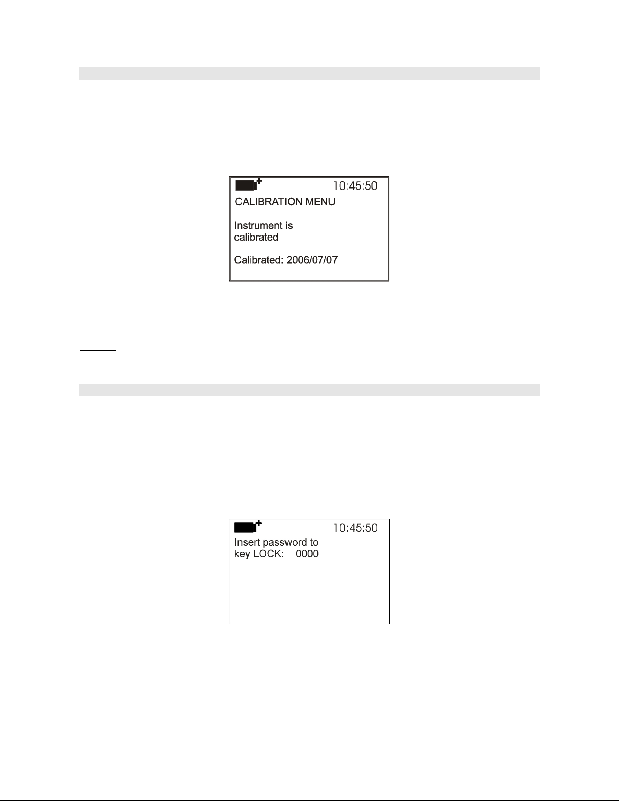
4.8 CALIBRATE
The Calibrate menu is reserved to Technical Support. It reports the last calibration date.
To access the Calibrate submenu, proceed as follows:
1. Press SETUP;
2. Use the arrows ▲▼◄► to select Calibrate;
3. Press ENTER;
4. You will get the following message
5. Press ENTER or ESC to return to the main menu: You cannot perform any change,
calibration is reserved to Technical Support;
6. Press SETUP to exit immediately from the main menu.
NOTE: The calibration date cannot be modified by the user.
4.9 KEY LOCK
This menu item allows to lock/unlock the instrument keyboard, when the password has been input.
See the next chapter for further details.
To access the Key lock submenu, proceed as follows:
1. Press SETUP;
2. Use the arrows ▲▼◄► to select Key lock;
3. Press ENTER;
4. You will get the following message: “Enter the password to lock the keyboard”
5. Use the arrows ▼▲ to enter the correct password;
6. Press ENTER to confirm (or ESC to cancel);
By pressing ENTER you return to the main menu and the instrument keyboard is locked: A “key”
is displayed on the upper left;

- 27 -
WARNING! When the instrument is locked by a password, all keys are locked, except MEM, used
to start the LOG session (data capture) and SETUP, ENTER and ESC that allow entering the main
menu to unlock the instrument.
Therefore the user has to first set all required parameters, protect the instrument using the
KEY LOCK function and start the LOG session, in order to prevent any undesired access by
unauthorized personnel.
To unlock the instrument, repeat the steps above: Enter the main menu and unlock the instrument
using the Key lock item and entering the password.
If the password is wrong, you will get the message “Wrong password”. The default password is
“0000” (four zeroes).
4.10 PASSWORD
This menu item allows to set a password to protect the instrument from unauthorized access. There
are two types of available passwords, both consisting of four characters:
• The user password: Can be set by the user to protect the instrument from unauthorized access;
• The factory password: Reserved to Technical Support
To access the Password submenu, proceed as follows:
1. Press SETUP;
2. Use the arrows ▲▼◄► to select Password;
3. Press ENTER;
4. You will get the following message
5. Use the arrows ▲▼ to select User password;
6. You will get the message “Insert old password” The default password is “0000” (four zeroes).
7. Use the ▼▲ arrows to enter the current password;
8. Press ENTER to confirm (or ESC to cancel);

- 28 -
9. You will get the message “Insert new password”;
10. Use the arrows ▼▲ to enter the new password;
11. Press ENTER to confirm (or ESC to cancel) and return to the main menu;
12. Press SETUP to exit immediately from the main menu.
WARNING! Using the User password you can lock/unlock the instrument (see Paragraph “4.9
KEY LOCK”).

- 29 -
5. PROBES AND MEASUREMENTS
You can connect the thermocouple temperature probes of type K, J, T, N, R, S, B and E to the
HD32.8.8 and HD32.8.16 dataloggers. The selection is done using the ▲▼ arrows (see chapter 3.
OPERATION).
The contacts of the thermocouple probe connector are polarized. They must be inserted on the
standard miniature socket located on the instrument in the correct direction. These probe positive
pole is usually marked with a "+" sign, as shown in the following drawing.
The user can choose the unit of measurement for display, printing and logging among the allowed
ones: °C, °F or °K.
All used probes must be the same type of thermocouple:
VTRAP32K
A tripod, code VTRAP32, is available for the
measurements. Adjustable height up to 1.50
meters, complete with head that can host up to 6
measurement probes. The same tripod can be
used to support the measurement instrument
during data capture.
The arms fitted with suitable clamps for the
measurement probes can be inserted in the head,
code HD3218K.
The VTRAP32K kit is composed of a tripod,
code VTRAP32, and 5 arms, code HD3218K.
The instrument is supplied with a belt that is
fastened to the two pull buttons on the instrument
side. Using this belt, the instrument can be
hanged on a hook or worn around the neck. Code
HD32CS.
5.1 TEMPERATURE MEASUREMENT
In all versions the thermocouple hot junction is housed in the end part of the probe.
The response time for the measurement of the temperature in air is greatly reduced if the air is
moving. If the air is st ill, stir the probe. The response times are longer than those for liquid
measurements.

- 30 -
The temperature measured by immersion is carried out by inserting the probe in the liquid where
you wish to perform the measurement; the hot junction is housed in the end part of the probe.
In the temperature measured by penetration the probe tip must be inserted into the material; the hot
junction is housed in the end part of the probe.
NOTE: When measuring the temperature on frozen blocks it is convenient to use a mechanical tool
to bore a cavity in which to insert the tip probe.
In order to perform a correct contact measurement, the measurement surface must be even and
smooth, and the probe must be perpendicular to the measurement plane.
So as to obtain the correct measurement, the insertion of a drop of oil or heat-conductive
paste between the surface and the probe is useful (do not use water or solvents). This
improves the response time and the measurement accuracy.
5.2 WARNINGS, CARE AND MAINTENANCE OF THE PROBES
• Do not expose the probes to gases or liquids that could corrode the material of the probe. Clean
the probes carefully after each measurement.
• Do not bend the probe connectors or force them upward or downward.
• Comply with the correct polarity of the probes.
• Do not bend or force the contacts when inserting the probe connector into the instrument.
• Do not bend, deform or drop the probes, as this could cause irreparable damage.
• Always select the most suitable probe for your application.
• To obtain reliable measurements, temperature variations that are too rapid must be avoided.
• The thermocouple could be non-insulated from its external casing. In this case, be very
careful not to come into contact with live parts (above 48V). This could be extremely
dangerous for the instrument as well as for the operator, who could be electrocuted.
• Avoid taking measurements in presence of high frequency sources, microwave ovens or large
magnetic fields; results may not be very reliable.
• The instrument is water resistant, but should not be immersed in water. Should the instrument
fall into the water, check for any water infiltration.
• For cleaning, use only detergents suitable to the different types of probes and instrument parts.
The thermocouple hot junction can be insulated or non-insulated from the probe’s earth. The probe
response time is faster in the thermocouples with an earthed junction.
The thermocouple insulation decreases with the temperature increase.
Insulated junction.
Earthed junction.
Exposed junction.

- 31 -
6. INSTRUMENT SIGNALS AND FAULTS
The following table lists the instrument indications, the errors and the information supplied to the
user.
Display indication Explanation
-----
This appears if the probe, already detected during turn on, is
disconnected or faulty.
Over
Overflow appears when the probe detects a higher value than expected
measurement range for that type of thermocouple.
Under
Underflow appears when the probe detects a lower value than
expected measurement range for that type of thermocouple.
WARNING:
MEMORY FULL!!
The instrument cannot store further data, the memory space is full.
This appears only if the circular memory is not enabled.

- 32 -
7. BATTERY SYMBOL AND BATTERY REPLACEMENT, MAINS POWER
SUPPLY
The battery symbol
on the display constantly shows the battery charge status. To the extent that batteries have
discharged, the symbol “empties”. When the charge decreases still further it starts blinking.
In this case, batteries should be replaced as soon as possible.
If you continue to use it, the instrument can no longer ensure correct measurement.
Data stored on memory are maintained even without power supply. When the symbol is completely
empty, the instrument shuts off.
The battery symbol becomes [~] when the external power supply is connected.
To replace the batteries, proceed as follows:
1. Switch the instrument off;
2. Disconnect the external power supply, if connected;
3. Unscrew the battery cover screw counter clockwise and take out the battery holder; Do not pull
the battery connection wires as they could break;
4. Replace the batteries (4 1.5V alkaline C-BABY batteries). Check that the battery polarity
matches the indication on the battery holder;
5. Replace the battery holder and fasten the cover’s screw clockwise.
6. Update the clock.
The instrument can be powered by the mains using, for example, the stabilized power supply
SWD10 input 100÷240Vac output 12Vdc – 1A.
The power supply positive (pole) must be connected to the central pin.
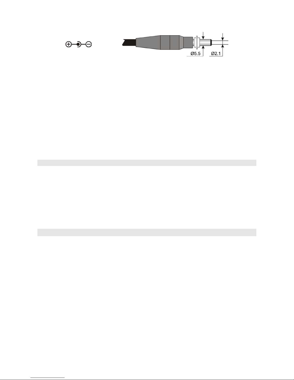
- 33 -
The external power supply connector has an external diameter of 5.5mm and an internal diameter of
2.1mm.
Warning: The power supply cannot be used as a battery charger. If the instrument is connected
to the external power supply, the [~] symbol is displayed instead of the battery symbol.
Malfunctioning upon turning on, after battery replacement
After replacing the batteries, the instrument may not restart correctly; in this case, repeat the
operation.
After disconnecting the batteries, wait a few minutes in order to allow circuit condensers to
discharge completely; then reinsert the batteries.
7.1 WARNINGS ABOUT BATTERY USE
• Batteries should be removed when the instrument is not used for an extended time.
• Flat batteries must be replaced immediately.
• Avoid loss of liquid from batteries.
• Use waterproof and good-quality batteries, if possible alkaline. Sometimes on the market, it
is possible to find new batteries with an insufficient charge capacity.
8. INSTRUMENT STORAGE
Instrument storage conditions:
• Temperature: -25…+65°C.
• Humidity: less than 90% RH without condensation.
• During storage avoid locations where:
• humidity is high;
• the instrument may be exposed to direct sunlight;
• the instrument may be exposed to a source of high temperature;
• the instrument may be exposed to strong vibrations;
• the instrument may be exposed to steam, salt or any corrosive gas.
Some parts of the instrument are made of ABS plastic, polycarbonate: do not use any incompatible
solvent for cleaning.

- 34 -
9. SERIAL INTERFACE AND USB
The HD32.8 is fitted with an electrically isolated RS-232C serial interface, and an USB 2.0
interface. Optionally, we can supply a serial cable with sub D 9-pole female connectors (code
9CPRS232) or a cable with USB 2.0 connectors (code CP22).
The USB connection requires the previous installation of a driver contained in the DeltaLog9 CDROM. Install the driver before connecting the USB cable to the PC (please see the
documentation provided with DeltaLog9 CD-ROM).
Standard parameters of the instrument RS232 serial transmission are:
• Baud rate 38400 baud
• Parity None
• N. bit 8
• Stop bit 1
• Protocol Xon/Xoff
It is possible to change the RS232C serial port baud rate by setting the “Baud Rate” parameter in
the menu (please see par. “4.3.1 The Baud Rate”). The possible values are: 38400, 19200, 9600,
4800, 2400, 1200. The other transmission parameters are fixed. To send the data to an 80 column
printer with serial input, check the maximum baud rate that can be set on the printer.
The USB 2.0 connection does not require the setting of parameters.
The selection of the port is carried out directly by the instrument: If the USB port is
connected to a PC, the RS232 serial port is automatically disabled and vice versa.
The instruments are provided with a complete set of commands and data queries to be sent via the
PC.
All the commands transferred to the instrument must have the following structure:
XXCR where: XX is the command code and CR is the Carriage Return (ASCII 0D)
The XX command characters are exclusively upper case characters. Once a correct command is
entered, the instrument responds with “&”; when any wrong combination of characters is entered,
the instrument responds with “?”.
The instrument response strings end with the sending of the CR command (Carriage Return) and LF
(Line Feed).
Before sending commands to the instrument via the serial port, locking the keyboard to avoid
functioning conflicts is recommended: Use the P0 command. When complete, restore the keyboard
with the P1 command.
Command Response Description
G0 Model HD32.8 Instrument model
G1 M=Thermocouple datalogger Model description
G2 SN=12345678 Instrument serial number
G3 Firm.Ver.=01.00 Firmware version
G4 Firm.Date=2007/10/12 Firmware date
G5 cal 0000/00/00 00:00:00 Calibration date and tim
e
GB User ID=0000000000000000 User code (set with T2xxxxxxxxxxxxxxxx)
K0
&
Stop printing data
K4
&
Start logging data
K5
&
Stop logging data
KP
&
Auto-power-off function = ENABLE
KQ
&
Auto-power-off function = DISABLE

- 35 -
Command Response Description
LDnn Print data stored in section nn. (nn= hexadecimal number 00-
63). If the section is empty: “-->No Log Data<--”
LEX
&
Cancel data stored in all sections.
LFnn Start on; 2007/01/01 00:37:32;
rec;000003
Print memory nn section status. The number, and storage start
date and time are displayed. (nn= hexadecimal number 00-63).
If the section is empty: “-->No Log Data<--”
LN 00 ; 01 ; 02 ; 03 ; . ; . ; . ; Print instrument memory map: If a section is allocated a
number is displayed, if it is free a point (.) is displayed.
P0 & Ping (locks the instrument keyboard for 70 seconds)
P1 & Unlocks the instrument keyboar
d
RA
Sample log = 30sec
Reading of LOG interval set
RL
Sample print = 0sec
Reading of PRINT interval set
S0 Printing of the current measurement of all inputs
S1 Printing of the REL current measurement of all inputs
WA#
&
Setting LOG interval.
# is a hexadecimal number 1…D that represents the position
of the interval in the list 2, 5, 10, …, 3600 seconds.
WC0
&
Setting SELF of
f
WC1
&
Setting SELF on
WL#
&
Setting PRINT interval.
# is a hexadecimal number 0…D that represents the position
of the interval in the list 0, 2, 5, 10, …, 3600 seconds.

- 36 -
10. STORING AND TRANSFERRING DATA TO A PC
The HD32.8 instrument can be connected to a personal computer via an RS232C serial port or USB
port, and exchange data and information through the Deltalog9 software (vers. 3.0 and later)
running in a Windows operating environment. It is possible to print the measured values on an 80
column printer (PRINT key) or store them in the internal memory using the Logging function
(MEM key). If necessary, the data stored in the memory can be transferred later to a PC.
10.1 THE LOGGING FUNCTION
The Logging function allows recording of the measurements registered by the probe connected to
the inputs. The time interval between two consecutive measurements can be set from 2 seconds to 1
hour. The logging starts by pressing the MEM key and ends by pressing the same key again: The
data memorized in this way form a continuous block of data.
See the description of the menu items on chapter “4. MAIN MENU”.
If the automatic turning off option between two recordings (see par. “4.2.2 Self Shut-off mode”) is
enabled, upon pressing the MEM key the instrument logs the first data and turns off. 15 seconds
before the next logging instant, it turns on again to capture the new sample, and then turns off.
The data stored in the memory can be transferred to a PC using the DeltaLog9 software (vers. 3.0
and later) or using the instrument File Manager (see par. “4.2.5 Log File Manager”). During data
transfer the display shows the message DUMP; to stop the data transfer press ESC on the
instrument or on the PC.
If during a logging session the batteries have discharged, the instrument stops recording and shuts
off. The data downloaded on the PC will indicate the logging interruption due to lack of power.
If the instrument is powered only by the mains and, during a logging session, there is a mains power
failure, the last record could be stored incorrectly.
During a logging session, we recommend to attach a charged battery pack and connect the external
power supply: This way, in case of a mains power failure, the batteries continue to power the
instrument.
10.1.1 Storage capacity
The storage capacity varies according to the number of probes connected to the instrument inputs.
The following table reports the number of samples that can be stored according to the number of
connected probes:
Number of connected
probes
Number of samples that
can be stored
1 800000
2 400000
3 264000
4 200000
5 160000
6 128000
7 112000
8 96000
9 88000
10 80000
11 72000
12 64000

- 37 -
Number of connected
probes
Number of samples that
can be stored
13 56000
14 56000
15 48000
16 48000
The time required to fill the memory depends on the number of connected probes and the selected
logging interval.
The following tables report this time, in the format days:hours:minutes:seconds.
Logging interval
2s 5s 10s 15s 30s 1min 2min
Number of connected probes
1 18:12:26:40 46:7:6:40 92:14:13:20 138:21:20:0 277:18:40:0 555:13:20:0 1111:2:40:0
2 9:6:13:20 23:3:33:20 46:7:6:40
69:10:40:0 138:21:20:0 277:18:40:0 555:13:20:0
3 6:2:40:0 15:6:40:0 30:13:20:0
45:20:0:0
91:16:0:0
183:8:0:0 366:16:0:0
4 4:15:6:40 11:13:46:40 23:3:33:20
34:17:20:0
69:10:40:0 138:21:20:0 277:18:40:0
5 3:16:53:20 9:6:13:20 18:12:26:40
27:18:40:0
55:13:20:0
111:2:40:0 222:5:20:0
6 2:23:6:40 7:9:46:40 14:19:33:20
22:5:20:0
44:10:40:0
88:21:20:0 177:18:40:0
7 2:14:13:20 6:11:33:20 12:23:6:40
19:10:40:0
38:21:20:0
77:18:40:0 155:13:20:0
8 2:5:20:0 5:13:20:0 11:2:40:0
16:16:0:0
33:8:0:0
66:16:0:0 133:8:0:0
9 2:0:53:20 5:2:13:20 10:4:26:40
15:6:40:0
30:13:20:0
61:2:40:0 122:5:20:0
10 1:20:26:40 4:15:6:40 9:6:13:20
13:21:20:0
27:18:40:0
55:13:20:0 111:2:40:0
11 1:16:0:0 4:4:0:0 8:8:0:0
12:12:0:0
25:0:0:0
50:0:0:0 100:0:0:0
12 1:11:33:20 3:16:53:20 7:9:46:40
11:2:40:0
22:5:20:0
44:10:40:0 88:21:20:0
13 1:7:6:40 3:5:46:40 6:11:33:20
9:17:20:0
19:10:40:0
38:21:20:0 77:18:40:0
14 1:7:6:40 3:5:46:40 6:11:33:20
9:17:20:0
19:10:40:0
38:21:20:0 77:18:40:0
15 1:2:40:0 2:18:40:0 5:13:20:0
8:8:0:0
16:16:0:0
33:8:0:0 66:16:0:0
16 1:2:40:0 2:18:40:0 5:13:20:0
8:8:0:0
16:16:0:0
33:8:0:0 66:16:0:0
Logging interval
5min 10min 15min 20min 30min 1h
Number of connected probes
1 2777:18:40:0 5555:13:20:0 8333:8:0:0 11111:2:40:0 16666:16:0:0 33333:8:0:0
2 1388:21:20:0 2777:18:40:0 4166:16:0:0 5555:13:20:0
8333:8:0:0 16666:16:0:0
3 916:16:0:0 1833:8:0:0 2750:0:0:0 3666:16:0:0
5500:0:0:0 11000:0:0:0
4 694:10:40:0 1388:21:20:0 2083:8:0:0 2777:18:40:0 4166:16:0:0
8333:8:0:0
5 555:13:20:0 1111:2:40:0 1666:16:0:0 2222:5:20:0
3333:8:0:0 6666:16:0:0
6 444:10:40:0 888:21:20:0 1333:8:0:0 1777:18:40:0 2666:16:0:0
5333:8:0:0
7 388:21:20:0 777:18:40:0 1166:16:0:0 1555:13:20:0
2333:8:0:0 4666:16:0:0
8 333:8:0:0 666:16:0:0 1000:0:0:0
1333:8:0:0
2000:0:0:0
4000:0:0:0
9 305:13:20:0 611:2:40:0 916:16:0:0 1222:5:20:0
1833:8:0:0 3666:16:0:0
10 277:18:40:0 555:13:20:0 833:8:0:0 1111:2:40:0 1666:16:0:0
3333:8:0:0
11 250:0:0:0 500:0:0:0 750:0:0:0
1000:0:0:0
1500:0:0:0
3000:0:0:0
12 222:5:20:0 444:10:40:0 666:16:0:0 888:21:20:0
1333:8:0:0 2666:16:0:0
13 194:10:40:0 388:21:20:0 583:8:0:0 777:18:40:0 1166:16:0:0
2333:8:0:0
14 194:10:40:0 388:21:20:0 583:8:0:0 777:18:40:0 1166:16:0:0
2333:8:0:0
15 166:16:0:0 333:8:0:0 500:0:0:0
666:16:0:0
1000:0:0:0
2000:0:0:0
16 166:16:0:0 333:8:0:0 500:0:0:0
666:16:0:0
1000:0:0:0
2000:0:0:0

- 38 -
10.1.2 The Erase function: clearing the memory
To clear the memory use the Erase Log function (see par. “4.2.5 Log File Manager”). The
instrument starts clearing the internal memory; at the end of the operation, it goes back to normal
display.
NOTES:
• Data transfer does not cause the memory to be erased: The operation can be repeated as many
times as required.
• The stored data remain in the memory independently of the battery charge conditions.
• In order to print the data to a parallel interface printer, you must use a parallel-serial adaptor (not
supplied).
• The direct connection between instrument and printer via a USB connector does not work.
• Some keys are disabled during logging. The following keys are enabled: MEM, SETUP, TIME,
ENTER and ESC.
10.2 THE PRINT FUNCTION
Press PRINT to send the measured data directly to the RS232 ports, in real time. The printed data
units of measurements are the same as those used on the display. The function is started by pressing
PRINT. The time interval between two consecutive prints can be set to 0 or from 2 seconds to 1
hour (please see the Print interval menu item in the par. “4.3.2 Print Interval”). If the print interval
is equal to 0, by pressing PRINT a single data is sent to the connected device. If the print interval is
higher than 0, the data transfer continues until the operator stops it by pressing PRINT again. The
“PN” message is displayed at the top of the display.

- 39 -
11. CONNECTION TO A PC
The HD32.8 is fitted with two ports for connecting the instrument to the PC:
- RS232C serial port with null modem cable code 9CPRS232. The cable has two sub D 9-pole
female connectors.
- USB 2.0 port with the cable code CP22. The cable has a USB type A connector for PC
connection and a USB type B connector for connection to the instrument.
The instrument is supplied with the DeltaLog9 software (vers. 3.0 and later). The software
manages the connection, data transfer, graphic presentation, and printing operations of the captured
or logged measurements.
The DeltaLog9 software is complete with an “On-line Help” (also in PDF format) describing
its characteristics and functions.
The instruments are also compatible with the HyperTerminal communication program supplied
with the Windows operating systems (from Windows 98 to Windows XP).
11.1 CONNECTION TO THE RS232C SERIAL PORT
1. The measuring instrument has to be switched off.
2. Using the null-modem Delta Ohm 9CPRS232 cable, connect the measurement instrument to the
first free serial port (COM) of the PC.
3. Turn on the instrument and set the baud rate to 38400 (SETUP key >> “Serial” >> “Baud Rate”,
select 38400 using the arrows and confirm with ENTER). The parameter remains in the memory.
4. Launch the DeltaLog9 software and press CONNECT. Wait for the connection to occur and
follow the instructions on the screen. For a description of the Deltalog9 application, please refer
to its On-line Help.
11.2 CONNECTION TO THE USB 2.0 PORT
Proceed as follows:
1. Do not connect the instrument to the USB port until you are expressly requested to do it.
2. Insert the DeltaLog9 CD-ROM and select “Install USB driver”.
3. The application checks the presence of the drivers on the PC: The installation starts if they are
not present; if they are already installed, the drivers are removed by pressing the key.
4. Follow the guide to the USB driver installat ion/removal included in the CD-ROM.

- 40 -
12. FUNCTIONING NOTES AND OPERATING SAFETY
Authorized use
Comply with the technical specifications outlined in the next chapter. Its use is authorized only in
conformity with the instructions written in this manual. Any different use is considered improper.
General instructions on security
This instrument has been manufactured and tested according to safety regulation EN 61010-1:2010
concerning electronic measurement instruments and was delivered ex factory in perfect security
condit ions.
Its regular functioning and operating safety can be ensured only if all the normal safety measures as
well as the specifications described in this manual are complied with.
Its regular functioning and operating security can be ensured only within the climatic conditions
specified in the chapter “TECHNICAL CHARACTERISTICS”.
Do not use or store the instrument in ways and/or places in which there are:
• Quick environment temperature changes that could cause condensation.
• Corrosive or inflammable gases.
• Direct vibrations or shocks against the instrument.
• High intensity electromagnetic fields, static electricity.
If the instrument is moved from a cold to a hot environment, the condensation can disturb its
functioning. In this case, you need to wait for the instrument to reach the environment temperature
before using it.
User obligations
The user of the instrument must ensure that the following regulations and directives concerning the
handling of hazardous materials are complied with:
• CEE directives on job safety
• National laws on job safety
• Accident prevention regulations

- 41 -
13. TECHNICAL CHARACTERISTICS
Instrument
Dimensions (Length x Width x Height) 220x180x50 mm
Weight 1100 g (batteries included)
Materials ABS, polycarbonate and aluminium
Display Backlit LCD, Dot Matrix
128x64 points, visible area 56x38mm
Operating conditions
Operating temperature -5 … 50°C
Warehouse temperature -25 … 65°C
Working relative humidity 0 … 90% RH without condensation
Protection degree IP64
Power
Batteries 4 1.5V alkaline C-BABY type batteries
Mains adapter (code SWD10) 12Vdc/1A, connector external ∅ 5.5mm,
internal ∅ 2.1mm
Power supply via the PC USB port.
Autonomy 200 hours with 7800mAh alkaline
batteries, and all probes connected
Power absorbed @6Vdc <60μA when the instrument is off
<60μA in sleep mode with all probes
connected
<40mA during data capture with all
probes connected
Security of stored data Unlimited
Connections
Number of inputs 8 for the HD32.8.8
16 for the HD32.8.16
Connection Miniature female socket
RS232C serial interface
Type RS232C electrically isolated
Baud rate Can be set from 1200 to 38400 baud
Data bit 8
Parity None
Stop bit 1
Flow Control Xon/Xoff
Serial cable length Max. 15 m
USB interface
Type 1.1 - 2.0 electrically isolated

- 42 -
Instrument accuracy and measurement range
Tc: K -200…+1370°C / ±0.1°C up to 600°C
±0.2°C over 600°C
Tc: J -100…+750°C / ±0.1°C up to 400°C
±0.2°C over 400°C
Tc: T -200…+400°C / ±0.1°C
Tc: N -200…+1300°C / ±0.1°C up to 600°C
±0.2°C over 600°C
Tc: R +200…+1480°C / ±0.3°C
Tc: S +200…+1480°C / ±0.3°C
Tc: B +200…+1800°C / ±0.4°C
Tc: E -200…+750°C / ±0.1°C up to 300°C
±0.2°C over 300°C
The precision only refers to the instrument. Error due to the thermocouple or to the cold junction
reference sensor is not included.
Resolution 0.05°C in the range ±199.95°C
0.1°C elsewhere
Temperature drift @20°C 0.02%/°C
Drift after 1 year 0.1°C/year
Internal clock accuracy 1min/month max. deviation
Unit of measurement °C, °F, °K
Keyboard 15 keys; the instruments can also be configured
without a PC.
Password and locking of the keyboard function.
Memory Divided in 64 blocks.
Storage capacity Up to 800,000 recordings divided amongst the
existing inputs; i.e. with one probe connected,
800,000 recordings, with 8 probes connected,
96,000 recordings.
Logging interval Selectable among: 2, 5, 10, 15, 30 seconds, 1,
2, 5, 10, 15, 20, 30 minutes, and 1 hour.
Dump LOG RS232C from 1200 to 38400 baud, electrically
isolated. Sub D 9-pole male connector.
USB 1.1 – 2.0 electrically isolated.
Probes It is possible to connect all the thermocouple
probes of type K, J, T, N, R, S, B, and E using
a male miniature connector.
In addition to the K probes available in the
catalogue, Delta Ohm can provide probes of
different type and shape on request.

- 43 -
Tolerance of the thermocouple probes:
The tolerance of a type of thermocouple corresponds to the maximum acceptable deviation from the
e.m.f. of any thermocouple of that type, with reference junction at 0°C. The tolerance is expressed
in degrees Celsius, preceded by the sign.
The tolerances refer to the operating temperature expected for the thermocouple, in agreement with
the diameter of the thermoelements.
TOLERANCE CLASSES OF THERMOCOUPLES
Tolerances according to IEC 60584-2 standard.
The values refer to thermocouples with reference junction at 0 °C.
Tolerance class 1 Tolerance class 2 Tolerance class 3
Type of
thermocouple
Temperature
range
(°C)
Tolerance
(°C)
Temperature
range
(°C)
Tolerance
(°C)
Temperature
range
(°C)
Tolerance
(°C)
B
--- --- +600…+1700
± 0.0025 ⋅ t
+600…+800 ± 4
--- --- --- --- +800…+1700
± 0.005 ⋅ t
E
-40…+375 ± 1.5 -40…+333 ± 2.5 -167…+40 ± 2.5
+375…+800
± 0.004 ⋅ t
+333…+900
± 0.0075 ⋅ t
-200…-167
± 0.015 ⋅ t
J
-40…+375 ± 1.5 -40…+333 ± 2.5 --- ---
+375…+750
± 0.004 ⋅ t
+333…+750
± 0.0075 ⋅ t
--- ---
K , N
-40…+375 ± 1.5 -40…+333 ± 2.5 -167…+40 ± 2.5
+375…+1000
± 0.004 ⋅ t
+333…+1200
± 0.0075 ⋅ t
-200…-167
± 0.015 ⋅ t
R , S
0…+1100 ± 1 0…+600 ± 1.5 --- ---
+1100…+1600
± [1+0.003
⋅
(t-1100)]
+600…+1600
± 0.0025 ⋅ t
--- ---
T
-40…+125 ± 0.5 -40…+133 ± 1 -67…+40 ± 1
+125…+350
± 0.004 ⋅ t
+133…+350
± 0.0075 ⋅ t
-200…-67
± 0.015 ⋅ t
Note: t = temperature of measurement junction in °C.

- 44 -
14. ORDERING CODES
HD32.8.8 8-input data logger instrument for temperature probes with thermocouples type
K, J, T, N, R, S, B, and E. The kit is composed of the HD32.8.8, 4 1.5V alkaline
C-BABY type batteries, operating manual, DeltaLog9 software (vers. 3.0 and
later), and bearing and transport belt. The probes, tripod support, suitcase and
cables must be ordered separately.
HD32.8.16 16-input data logger instrument for temperature probes with thermocouples type
K, J, T, N, R, S, B, and E. The kit is composed of the HD32.8.16, 4 1.5V alkaline
C-BABY type batteries, operating manual, DeltaLog9 software (vers. 3.0 and
later). The probes, tripod support, suitcase and cables must be ordered
separately.
DeltaLog9 Additional copy of the software (vers. 3.0 and later) for download and
management of the data on PC using Windows (from 98) operating systems.
HD32.8.8 and HD32.8.16 probes
It is possible to connect all the temperature probes with thermocouples type K, J, T, N, R, S, B, and
E using a male miniature connector.
Different probes can be supplied on request.
HD32.8.8 and HD32.8.16 accessories
9CPRS232 Connection cable with sub D 9-pole female connectors for RS232C (null modem)
CP22 Connection cable USB 2.0 connector type A - connector type B.
BAG32.2 Suitcase for the HD32.8 instrument and accessories
HD32CS Instrument bearing and transport belt.
SWD10 Stabilized power supply at 100-240VAC/12VDC-1A mains voltage
VTRAP32 Tripod complete with 6 input head and 5 probe holder, code HD3218K
HD3218K Rod for another probe.
DELTA OHM metrology laboratories LAT N° 124 are accredited by ACCREDIA for
Temperature, Humidity, Pressure, Photometry / Radiometry, Acoustics and Air Velocity.
They can supply calibration certificates for the accredited quantities.

- 45 -
NOTES

- 46 -
NOTES

DICHIARAZIONE DI CONFORMITÀ UE
EU DECLARATION OF CONFORMITY
GHM Messtechnik GmbH location Delta OHM, via G. Marconi 5, 35030 Selvazzano (PD), Italy
Documento Nr. / Mese.Anno:
Document-No. / Month.Year :
5022 / 12.2016
Si dichiara con la presente, in qualità di produttore e sotto la propria responsabilità esclusiva, che i seguenti prodotti
sono conformi ai requisiti di protezione definiti nelle direttive del Consiglio Europeo:
We declare as manufacturer herewith under our sole responsibility that the following products are in compliance
with the protection requirements defined in the European Council directives:
Codice prodotto:
Product identifier :
HD32.8.8 – HD32.8.16
Descrizione prodotto:
Product description :
Datalogger Termocoppia
Thermocouple Data Logger
I prodotti sono conformi alle seguenti Direttive Europee:
The products conform to following European Directives:
Direttive / Directives
2014/30/EU
Direttiva EMC / EMC Directive
2014/35/EU
Direttiva bassa tensione / Low Voltage Directive
2011/65/EU
RoHS / RoHS
Norme armonizzate applicate o riferimento a specifiche tecniche:
Applied harmonized standards or mentioned technical specifications:
Norme armonizzate / Harmonized standards
EN 61010-1:2010
Requisiti di sicurezza elettrica / Electrical safety requirements
EN 61326-1:2013
Requisiti EMC / EMC requirements
EN 50581:2012
RoHS / RoHS
Il produttore è responsabile per la dichiarazione rilasciata da:
The manufacturer is responsible for the declaration released by:
Luisa Masut
Amministratore delegato
Chief Executive Officer
Caselle di Selvazzano, 12/12/2016
Questa dichiarazione certifica l’accordo con la legislazione armonizzata menzionata, non costituisce tuttavia garanzia
delle caratteristiche.
This declaration certifies the agreement with the harmonization legislation mentioned, contained however no
warranty of characteristics.

GUARANTEE
TERMS OF GUARANTEE
All DELTA OHM instruments are subject to accurate testing, and are guaranteed for 24 months from the
date of purchase. DELTA OHM will repair or replace free of charge the parts that, within the warranty
period, shall be deemed non efficient according to its own judgement. Complete replacement is excluded
and no damage claims are accepted. The DELTA OHM guarantee only covers instrument repair. The
guarantee is void in case of incidental breakage during transport, negligence, misuse, connection to a
different voltage than that required for the appliance by the operator. Finally, a product repaired or
tampered by unauthorized third parties is excluded from the guarantee. The instrument shall be returned
FREE OF SHIPMENT CHARGES to your dealer. The jurisdiction of Padua applies in any dispute.
The electrical and electronic equipment marked with this symbol cannot be disposed of in public
landfills. According to the Directive 2011/65/EU, the european users of electrical and electronic
equipment can return it to the dealer or manufacturer upon purchase of a new one. The illegal
disposal of electrical and electronic equipment is punished with an administrative fine.
This guarantee must be sent together with the instrument to our service centre.
IMPORTANT: Guarantee is valid only if coupon has been correctly filled in all details.
Instrument Code:
HD32.8.8 HD32.8.16
Serial Number
RENEWALS
Date Date
Inspector Inspector
Date Date
Inspector Inspector
Date Date
Inspector Inspector
 Loading...