


The kit for the WBGT analysis is composed of:
• HD32.2 instrument, 4 alkaline batteries 1.5 V AA type, instruction manual, case.
• DeltaLog10 Software for warm environments: WBGT analysis.
The necessary probes for the WBGT measurement are:
• TP3207.2 or TP3207 dry bulb temperature probe
• TP3276.2 or TP3275 globe thermometer probe.
• HP3201.2 or HP3201 natural ventilation wet bulb temperature probe
Our instruments' quality level is the results of the product continuous development. This
can bring about differences between the information written in this manual and the instrument that you purchased. We cannot entirely exclude errors in the manual, for which we
apologize.
The data, figures and descriptions contained in this manual cannot be legally asserted. We
reserve the right to make changes and corrections without prior notice.
HD32.2
WBGT INDEX
ENGLISH
REV. 1.3
31/01/2013

- -
2
WBGT
Wet Bulb Globe Temperature Meter
HD32.2

- -
3
HD32.2
1. Inlets for SICRAM probes.
2. Inlet for power supply.
3. Back - enlightened graphic display.
4. Navigation key ▲: it allows the navigation through the menus. During the normal working it se-
lects the reset of statistic data.
5. ESC key: it allows exiting from the menu or, in case of a submenu, exiting from the current
level display.
6. Navigation key ◄: it allows the navigation through the menus. During a normal visualization, it
allows to visualize the statistic data: maximum, minimum and medium.
7. MEM key: it starts and ends the recording of the data (logging).
8. Navigation key ▼: it allows the navigation through the menus. During the normal working it
cancels the reset choice of statistic data.
9. MENU key: It allows entering or exiting from the instrument working parameters setting menu.
10. Navigation key ►: it allows the navigation through the menus.
11. ENTER key: it confirms the inserted data inside the menu. During the normal visualization, it
allows resetting the statistic data and immediately printing the data on HD40.1 printer.
12. ON/OFF key: it switches the instrument on and off.
13. RS232 and USB serial ports.

- -
4
TABLE OF CONTENTS
1. GENERAL FEATURES ...................................................................................................................................... 5
2. WORKING PRINCIPLE ..................................................................................................................................... 6
3. USER INTERFACES ........................................................................................................................................... 8
3.1 THE DISPLAY ...................................................................................................................................................... 8
3.2 THE KEYBOARD ................................................................................................................................................. 9
4. WORKING ..........................................................................................................................................................11
4.1.1 The measurement “Unit” .........................................................................................................................12
4.1.2 The immediate printing of the data ...........................................................................................................12
4.1.3 The maximum, minimum and medium values of the detected sizes .............................................................12
4.1.4 Instrument setting ....................................................................................................................................13
4.1.5 Start a memorization section (Logging) ....................................................................................................13
5. THE MAIN MENU .............................................................................................................................................14
5.1 INFO ABOUT MENU ..........................................................................................................................................14
5.2 LOGGING MENU ..............................................................................................................................................16
5.2.1 Log Interval .............................................................................................................................................16
5.2.2 Self Shut-off mode – The automatic switching off ......................................................................................17
5.2.3 Start/stop time – The automatic start ........................................................................................................18
5.2.4 Cancel auto start .....................................................................................................................................19
5.2.5 Log File Manager ....................................................................................................................................21
5.3 SERIAL MENU (S ERI AL COMMUNI CATIO N)..........................................................................................................24
5.3.1 Baud Rate ...............................................................................................................................................25
5.3.2 Print Interval ...........................................................................................................................................25
5.4 RESET..............................................................................................................................................................26
5.5 CONTRAST .......................................................................................................................................................26
6. PROBES AND MEASUREMENTS ....................................................................................................................27
6.1 Instruction, accuracy and maintenance of the probes ..................................................................................30
7. SERIAL AND USB INTERFACES ....................................................................................................................31
7.1 THE DATA MEMORIZATION AND THE DATA TRANSFER TO A PC ...........................................................................33
7.1.1 Logging function......................................................................................................................................33
7.1.2 Erase function: cancellation of the memorized data ..................................................................................33
7.1.3 Print function ..........................................................................................................................................33
8. CONNECTION TO A PC ...................................................................................................................................34
8.1 CONNECTION TO RS232-C SERIAL PORT............................................................................................................34
8.2 CONNECTION TO USB 2.0 PORT ........................................................................................................................34
9. INSTRUMENT SIGNALS AND FAULTS .........................................................................................................36
10. BATTERY SYMBOL AND BATTERY REPLACEMENT – MAIN POWER SUPPLY ................................37
10.1 WARNING ABOUT THE BATTERIES USE .............................................................................................................37
11. INSTRUMENT STORAGE ..............................................................................................................................38
12. PRINTING OF THE MEASUREMENT REPORT .........................................................................................39
13. TECHNICAL FEATURES ...............................................................................................................................45
14. ORDERING CODES .........................................................................................................................................47
14.1 PROBES FOR HD32.2 WBGT INDEX.............................................................................................................47

- -
5
1. GENERAL FEATURES
HD32.2 is designed for WBGT (Wet Bulb Globe thermometer temperature) index analysis in presence or absence of solar radiation. The instrument is provided with three inputs for probes with SICRAM module: the probes have an electric circuit that communicates with the instrument; the sensor calibration data are saved in its permanent memory.
All the SICRAM probes can be inserted in one of the inputs: they are automatically recognized
when you switch the instrument on.
The main features of the instrument are:
• Logging: acquisition and memorization of data inside the instrument. Memory capacity: 64
different logging sections, with the possibility to set the acquisition interval of the samples.
You can set the duration of the memorization and, with auto-start function; it’s possible
to set the starting and finishing date and the hour of data memorization.
• The measurement unit of the temperature visualized sizes: °C, °F, °K.
• The system date and hour.
• The visualization of the maximum, minimum and medium statistic parameters and their
cancellation.
• The transfer speed of the data through the serial port RS232.
NOTE: The set acquisition interval is the same for all the probes connected to the instrument.
HD32.2 instrument can contemporarily detect the following sizes:
• Globe thermometer temperature Tg.
• Wet bulb with natural ventilation temperature Tn.
• Ambient temperature T.
On the basis of the detected measurements, HD32.2 can calculate:
• WBGT(in) index (Wet Bulb Glob Temperature: wet bulb and globe thermometer tempera-
ture) in presence or absence of solar irradiation.
• WBGT(out) index (Wet Bulb Glob Temperature: wet bulb and globe thermometer tempera-
ture) in presence of solar irradiation.

- -
6
2. WORKING PRINCIPLE
Microclimate term means the environmental parameters that influence the thermal exchanges be-
tween the being and the environments inside limited places and that determinate the so-called
“thermal well-being”.
The micro-environmental weather factors together with your own job influence a series of your biologic responses connected to well-being situations (Comfort) or thermal uneasiness (Discomfort).
In fact, the human body tries to keep the thermal balance in equilibrium conditions in order to keep
the body temperature on optimal values.
HD32.2 detects the following sizes:
• tnw: wet bulb with natural ventilation temperature probe
• tg: globe thermometer temperature
• ta: ambient temperature
It realizes direct measurements with the probes connected to the instrument and it also calculates
and directly visualizes WBGT index.
WBGT (Wet Bulb Globe Temperature) - wet bulb and globe thermometer temperature - is one of
the indexes used for determining the thermal stress to which is submitted a being in a warm environment. It represents the value, with reference to the metabolic waste connected to a special job,
over which the being is in a thermal stress condition. WBGT index combines the temperature measurement of natural ventilation wet bulb t
nw
with the Glob thermometer tg and, in some situations,
with the air temperature ta. The formula for the calculation is the following one:
• inside and outside the buildings in absence of solar irradiation:
WBGT
close environments
= 0,7 tnw + 0,3 t
g
• outside the building in presence of solar irradiation:
WBGT
external environments
= 0,7 tnw + 0,2 tg + 0,1 t
a
where:
t
nw
= natural ventilation wet bulb temperature
t
g
= globe thermometer temperature;
t
a
= air temperature.
The detected data must be compared with the limit values established by the regulation; if they are
over passed, it’s necessary to:
• directly decrease the thermal stress in the considered working place;
• go on with a detailed analysis of the thermal stress.
- -
7
In the following table are indicated the limit values of the WBGT thermal stress index taken from
ISO 7243 regulation:
LEVEL CLASS
METABOLIC
METABOLIC LEVEL, M WBGT LIMIT VALUE
RELATIVE TO A
SINGLE SKIN
SURFACE
W/m
2
TOTAL (FOR A
MEDIUM AREA OF
1,8 m
2
SKIN SURFACE
W
ACCLIMATIZED BEING TO
HEAT
°C
PERSONA NON ACCLIMATATA
AL CALORENON- ACCLIMA-
TIZED BEING TO HEAT
°C
0
(RESTING)
M ≤ 65 M ≤ 117 33 32
1 65 < M ≤ 130 117 < M ≤ 234 30 29
2 130 < M ≤ 200 234 < M ≤ 360 28 26
3 200 < M ≤ 260 360 < M ≤ 468
STAGNANT
AIR
25
NO STAGNANT
AIR
26
STAGNANT
AIR
22
NO STAGNANT
AIR
23
4 M > 260 M > 468 23 25 18 20
NOTE: THE VALUES ARE STABILIZED, CONSIDERING A MAXIMUM RECTAL TEMPERATURE OF
38° C FOR THE CONSIDERED BEINGS.
To calculate WBGT index, it’s necessary that to the instrument are connected:
• HP3201.2 or HP3201 temperature probe with natural ventilation wet bulb.
• TP3276.2 or TP3275 globe thermometer.
• TP3207.2 or TP3207 wet bulb temperature probe if the detection is made in presence
of solar irradiation.
To measure WBGT index consider the following regulations:
• ISO 7726
• ISO 7243

- -
8
3. USER INTERFACES
The user interface is composed of an LCD graphic back - enlighten display and start and set keys
of the instrument. With a battery power supplying without pressing any key, the back- lighting
switches off after 1 minute. To activate it again, press one key. With external power supply, the
back-lighting is always activated.
To switch the instrument on and off, press ON/OFF key. When you switch it on, the logo and the
model of the instrument will be visualize, for some seconds, then you can go to the main visualization.
3.1 THE DISPLAY
WBGT Index
2008/11/28 08:00:00
Log 00 00:00:00
Tn 15.6 °C
Tg 20.2 °C
T 20.2 °C
WBGT(in) 17.0 °C
WBGT(out) 17.0 °C
The first line visualizes the charge condition of the battery, the second line indicates the current
date and the current hour. If logging function is activated, the third line indicates the current log-
ging number and the spent time from the logging start.
The detected sizes are:
Tn: wet bulb with natural ventilation temperature
Tg: globe thermometer temperature
T: ambient temperature
WBGT (in): WBGT index in absence of direct solar irradiation
WBGT (out): WBGT index in presence of direct solar irradiation

- -
9
3.2 THE KEYBOARD
The instrument keys have the following functions:
ON-OFF / AUTO-OFF key
ON-OFF : it allows switching the instrument on and off.
When you switch the instrument on, the first screen will be visualized and, after some seconds, the
detected measurements will be visualized.
AUTO-OFF is on if the instrument is supplied with batteries. The instrument switches off after 8
minutes from the switching on. When you switch the instrument on, the AUTO-OFF function can
be disabled pressing together ESC and ON/OFF keys.
MENU key
It allows entering and exiting from the setting menu of the instrument working parameters.
ENTER key
Inside the menu for confirming the inserted data.
During a normal working:
• it confirms the choice to reset the statistic data.
• it prints the immediate data on HD40.1 printer.
ESC key
You exit from the menu or, if there is a submenu, you exit from the current level visualization.
MEM key
It allows starting and stopping a “logging” section (data memorization); the interval for sending
data must be set from the menu.
◄/FUNC key
◄ It allows the navigation through the menus.
FUNC: during a normal visualization, it allows to select some statistic data: maximum, minimum
and medium.
▲key
It allows the navigation through the menus. During a normal working, it selects the reset of statistic
data.

- -
10
▼key
It allows the navigation through the menus. During a normal working, it cancels the choice to reset
the statistic data.
►/UNIT key
► It allows the navigation through the menus.
UNIT: it allows selecting the temperature measurement unit: °C, °F, °K.

- -
11
4. WORKING
Before switching the instrument on, connect the SICRAM probes to the inlets: 8 pin male
connector DIN 45326 that is on the bottom of the instrument.
NOTE: The probes must be connected to the instrument off. If you connect a new probe to the
instrument already switched on, it isn't recognized, so it's necessary to switch the instrument
off and switch it on again.
If you connect a probe with the instrument switched on, you have an acoustic alarm (a beep per
second) and you can visualize it on the display in correspondence of a disconnected physical size,
the “LOST” message will be visualized.
If you insert more probes of the same type, it will be only consider the first recognized probe:
the scansion of the probes, for their recognition, happens from the inlet 1 up the inlet 3.
When you switch the instrument on, on the display appears the following writing for at least 10 seconds:
HD32.2 WBGT Index
Firm.Ver.=01.00
In addition to Delta Ohm logo are indicated the instrument code and the firmware version.
After connecting the probes, switch the instrument on: the display, after 10 seconds, will appear in
the measurement visualization mode:
WBGT Index
2008/11/28 08:00:00
Log 00 00:00:00
Tn 15.6 °C
Tg 20.2 °C
T 20.2 °C
WBGT(in) 17.0 °C
WBGT(out) 17.0 °C
Tn: wet bulb temperature with natural ventilation
Tg: globe thermometer temperature, detected by the globe thermometer probe
T: ambient temperature, detected by Pt100 probe
WBGT (in): WBGT index calculated in absence of solar irradiation
WBGT (out): WBGT index calculated in presence of solar irradiation

- -
12
4.1.1 The measurement “Unit”
Pressing ►/ UNIT key, it’s possible to visualize the temperature in degrees °C (Celsius), °F (Fahrenheit) or °K (Kelvin).
4.1.2 The immediate printing of the data
Pressing Enter key, it’s possible to print the immediate data on HD40.1 printer.
Example of immediate printing of the data, obtained using HD40.1 printer.
NOTES
========================
ISO 7243 WBGT Index
Reference regulation
========================
Model HD32.2 WBGT Index
Instrument model
Firm.Ver.=01.00
Instrument firmware version
Firm.Date=2008/12/05
Instrument firmware date
SN=12345678
Instrument serial number
ID=0000000000000000
Identification code
------------------------
Probe ch.1 description
Description of the probe connected to the inlet 1
Type: Pt100
Data cal.:2008/10/01
Serial N.:08109450
------------------------
Probe ch.2 description
Description of the probe connected to the inlet 2
Type: Pt100 Tg 50
Cal. date.:2008/10/01
Serial N.:08109452
------------------------
Probe ch.3 description
Description of the probe connected to the inlet 3
Type: Pt100 Tw
Cal. date.:2008/10/01
Serial N.:08109454
========================
Date=2008/11/21 15:00:00
Date and hour
Tnw 21.2 °C
Wet bulb temperature with natural ventilation
Globe thermometer temperature
Tg 24.9 °C
Wet bulb temperature
Ta 31.3 °C
WBGT in absence of direct solar irradiation
WBGT (i) 22.3 °C
WBGT in presence of direct solar irradiation
WBGT (o) 23.0 °C
========================
Notes:
========================
4.1.3 The maximum, minimum and medium values of the detected sizes
Pressing ◄/FUNC key, it’s possible to visualize the maximum, minimum and medium value of the
detected sizes.
To reset the statistic data, press ◄/FUNC key till “Clear Func? Yes No” writing doesn’t appear.
Select Yes with ▲▼ keys and confirm with ENTER key.
NOTE: Once selected, for example, max, all the visualized sizes indicate the maximum value. The
average is calculated on the number of samples belonging to the first five minutes and then,
considering the current average.

- -
13
4.1.4 Instrument setting
To set the instrument up, you enter to the main menu, pressing MENU key. For more details, see
the chapter 5.
4.1.5 Start a memorization section (Logging)
To start a Logging section, press MEM key: the key starts and stops the memorization (Logging) of
a data block that will be kept into the instrument internal memory. The frequency with which the
data are memorized is set with "Log interval" menu parameter. The memorized data between a
start and a following stop represent a measurement block.
With the memorization function on, LOG and number of logging section appears on the display; a
beep is given out during each memorization.
To finish the logging, press MEM key again.
The instrument can switch off during the logging between an acquisition and the following one: the
function is controlled by Auto_shut_off_Mode parameter. With a memorization interval less than
one minute, the instrument remains always on during the logging; with an interval of at least one
minute, it switches off between an acquisition and the following one.

- -
14
5. THE MAIN MENU
To visualize the programming menu, press MENU key:
WBGT Index
2008/11/10 08:00:00
MAIN MENU
Info
Logging
Serial
Reset
Contrast
<ESC> exit/cancel
If you don’t press any key for at least 2 minutes, the instrument will be back to the main
visualization.
To select a heading, use ▲▼ arrow keys and press ENTER.
To exit from the selected heading and be back to the previous menu level, press ESC.
To exit directly from the main menu, press MENU again.
5.1 INFO ABOUT MENU
Pressing MENU key, you enter into the main menu. To enter to Info menu, select Info heading
with ▲▼ keys and press ENTER.
WBGT Index
2008/11/10 08:00:00
INFO
Info Instrument
Info Probe
Time/Date
<UP> <DOWN> select
<ENTER> confirm
<ESC> exit/cancel
Selecting Info Instrument, you can visualize the information involving the instrument: instrument
code and operative programm, firmware version anda date, serial number, instrument calibration
date and identification code.
WBGT Index
2008/11/10 08:00:00
INFO INSTRUMENT
Model HD32.2
Firm.Ver.=01.00
Firm.Date=2008/06/30
Ser. Number=08010000
Calib: 2008/11/10
ID: 0000000000000000

- -
15
To modify the ID, press ENTER. Select the heading that you want to change with ◄► arrows and
modify it with ▲▼ arrows. Go on with the other headings and, at the end, confirm with ENTER
key.
Selecting Info Probe you can visualize the information involving the probes connected to the inlets:
INFO PROBE
Ch.1:Pt100Tg_50
Cal=2008/06/20
SN=08018422
Ch.2:Pt100
Cal=2008/06/21
SN=08018423
Ch.3:Pt100Tw
Cal=2008/06/20
SN=08018424
INFO ABOUT PROBE:
Description of the probe connected to the inlet 1.
Calibration data of the probe connected to the inlet 1.
Serial number of the probe connected to the inlet 1.
Description of the probe connected to the inlet 2.
Calibration data of the probe connected to the inlet 2.
Serial number of the probe connected to the inlet 2.
Description of the probe connected to the inlet 3.
Calibration data of the probe connected to the inlet 3.
Serial number of the probe connected to the inlet 3.
To go back to the main menu, press ESC. To exit from the menu, press MENU.
Time/Date allows to set the date and the hour that will appear on the upper part of the display.
To enter into Time/date, go on as indicated below:
1. using ▼▲ arrow keys, select Time/date heading
2. press ENTER
3. the messagge will be visualized
2008/11/10 08:00:00
enter date/time
<- arrows change ->
<ENTER> confirm
and set 00 seconds !
year/mm/dd hh:mm
2008/11/28 11:10:26
4. use ◄► arrows to select the data to set (year/month/day – hour : minutes)
5. once selected, the data will start flashing;
6. using ▼▲ arrows, insert the right value;

- -
16
7. press ENTER to confirm and go back to the main menu;
8. or press ESC to go back to the menu, without modifying anything;
9. press MENU to exit directly from the main menu.
NOTE: With reference to the time, you can set hour and minuted, the seconds are always set at 00
(set 00 seconds!).
5.2 LOGGING MENU
Press MENU key to enter into the main menu;
• Select Logging heading using ▲ ▼ keys;
• press ENTER: the submenu for the parameters setting involving the Logging section (to
aquired) is visualized.
WBGT Index
2008/11/10 08:00:00
LOGGING MENU
Log interval
Self shut_off mode
Start/stop time
Cancel auto start
Log file manager
<ESC> exit/cancel
5.2.1 Log Interval
Through this heading, it’s possible to set the LOG interval (interval between two acquisition
following samples): to set, go on as indicated below:
enter into LOGGING submenu (previus paragraph), select Log Interval heading using ▲ ▼ arrow
keys:
WBGT Index
2008/11/10 08:00:00
LOGGING MENU
input LOG interval
as h:mm:ss (1h max)
arrows to correct
or <ESC> now set at:
0:00:15
1. Using ▲ ▼ arrow keys select the interval duration that is between a minimum of 15 seconds and
a maximum of one hour.
2. Press ENTER to confirm and go back to Logging menu.
3. To go back to Logging menu without modifying anything, press ESC.
4. To go back to the main menu, press ESC again.
5. To exit directly from the menu, press MENU.
The values that youc an set are the following ones: 15 seconds - 30 seconds - 1 minute - 2 minutes 5 minutes- 10 minutes - 15 minutes -20 minutes - 30 minutes – 1 hour

- -
17
5.2.2 Self Shut-off mode – The automatic switching off
Self shut-off mode heading controls the instrument automatic switching off mode during the
logging between the acquisition of a sample and the following one. With an interval less than 60
seconds, the instrument will always remain on. With intervals upper or equal to 60 seconds, it's
possible to choose switching the instrument off bet ween the memorizations: it will switch on in
correspondence of the sampling time and it will switch off after some seconds, so extending the life
of the batteries.
Once you entered into LOGGING sub menu (previous paragraph), select Self shut_off mode
heading using ▲ ▼ arrow keys:
• If the set Log Interval (see the previous paragraph) is less than 60 seconds, there will be
visualized:
WBGT Index
2008/11/10 08:00:00
Log interval<60 sec
During log session
the instrument
will STAY ON
between samples
• If the set Log Interval (see the previous paragraph) is upper or equal to 60 seconds, there will
be visualixed:
WBGT Index
2008/11/10 08:00:00
Log interval>=60 sec
During log session
the instrument
will SHUT OFF
between samples
1. Pressing ▲ ▼arrows, you can select:
STAY ON (the inswtrument remains on)
SHUT OFF (the instrument remains off)
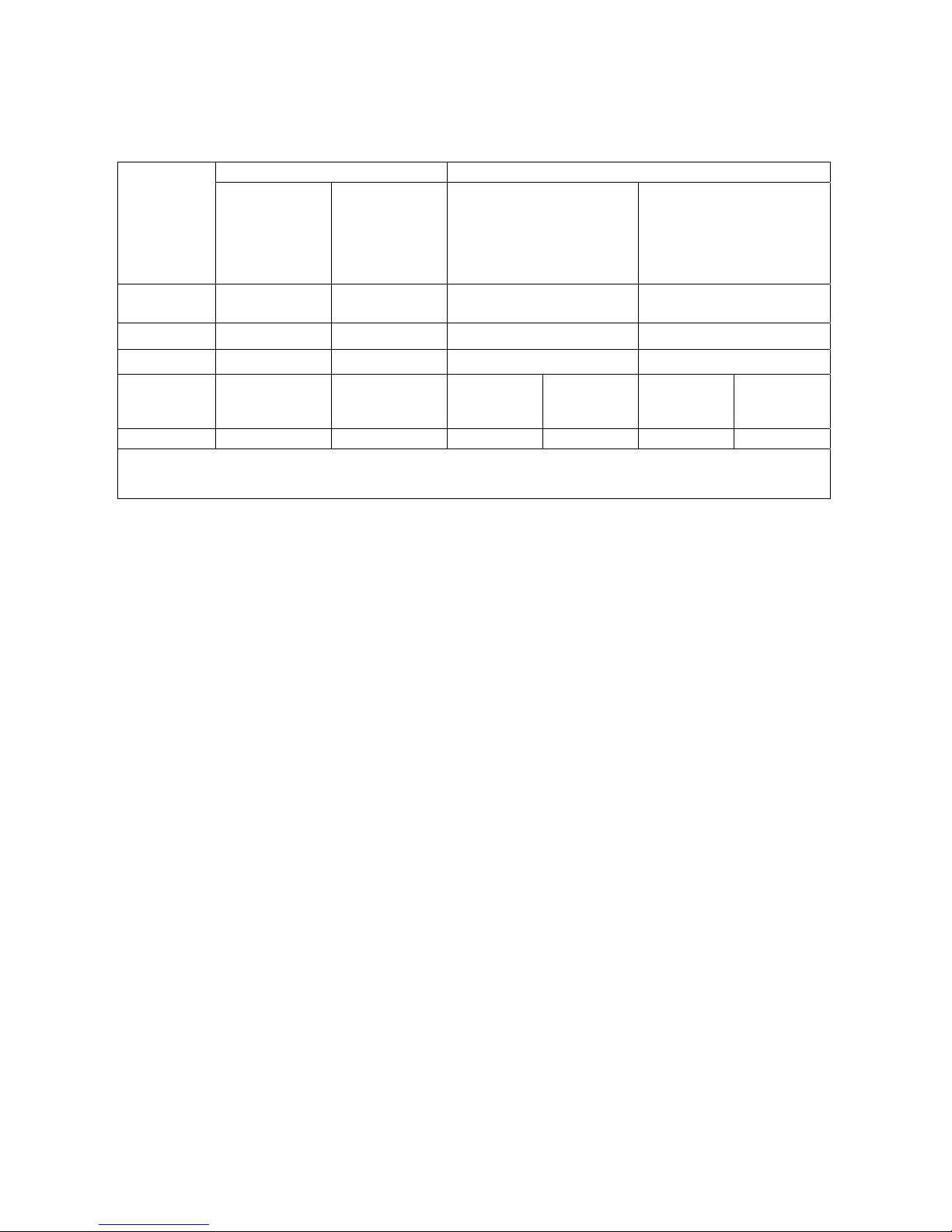
Memorization
interval
Memory capacity
Memorization
interval
Memory capacity
15 seconds About 11 days and 17 hours 10 minutes About 1 year and 104 days
30 seconds About 23 days and 11 hours 15 minutes About 1 year and 339 days
1 minute About 46 days and 22 hours 20 minutes About 2 years and 208 days
2 minutes About 93 days and 21 hours 30 minutes About 3 years and 313 days
5 minutes About 234 days and 17 hours 1 hour About 7 years and 261 days

- -
18
2. To go back to Logging menu, press ESC.
3. To go back to the main menu, press ESC again.
4. To exit directly from the menu press MENU.
5.2.3 Start/stop time – The automatic start
The start and the end of the memorization can be programmed inserting the date and the hour.
The function offers, as start hour, the current hour will increase of 5 minutes: to confirm, press
<ENTER>, vice versa set the date and the hour using the arrows. So it’s requested to set the data for
ending the memorization: in a default mode, the instrument offers the start hour increased of 10
minutes. The values offered in default mode are such to allow the user arranging the instrument for
the measurement.
NOTE: in a default mode, the set time is more than 5 minutes with reference to the current
hour.
For the setting, go on as indicated below.
Once entered into LOGGING submenu, select Start/Stop time heading using ▲ ▼ arrow keys:
“Enter start time” messagge will be visualized as indicated below:
WBGT Index
2008/11/10 08:00:00
enter start time
arrows to correct
<ENTER> confirm
default= 5m>RealTime
2008/11/28 10:29:00
1. using ◄ ► arrow key select the data to modify (year/month/day and hour/minutes/seconds);
2. once selected, the data will start flashing;
3. change the valued with ▼▲ keys;
4. confirm pressing ENTER;
5. to be back to Logging menu without modifying anything, press ESC;
6. to be back to the main menu, press ESC again;
7. to exit directly from the main menu, press MENU.
After setting the time of the memorization start, there will be visualized the request screen for
inserting the end memorization time (enter stop time):
WBGT Index
2008/11/10 08:00:00
enter stop time
arrows to correct
<ENTER> confirm
default=10m>RealTime
2008/11/28 10:39:00

- -
19
1. using ◄ ► arrow key select the data to modify (year/month/day and hour/minutes/seconds);
2. once selected, the data will start flashing;
3. change the valued with ▼▲ keys;
4. confirm pressing ENTER;
5. to be back to Logging menu without modifying anything, press ESC;
6. to be back to the main menu, press ESC again;
7. to exit directly from the main menu, press MENU.
NOTE: in a default mode, the set end acquisition time is more than 10 minutes with reference
to the start time of Logging section..
1. Once set both the values, the summary of the times will be visualized: date and hour of start and
end of LOG section.
WBGT Index
2008/11/10 08:00:00
<ENTER> confirm
Start time
2008/11/28 10:29:00
End time
2008/11/28 10:39:00
<ESC> exit/cancel
2. Press ENTER to confirm or ESC to exit without activating the automatic start: in both the cases,
you go back to LOGGING menu.
3. Press MENU to exit directly from the main menu.
When the instrument starts a LOG section in an automatic mode, a beep is given out for each
acquisition and, in the upper part of the display, LOG flashing heading will appear.
To stop the section befor the set stop time, press MEM key.
To cancel the settingf of the automatic start, use Cancel auto start function, described in the
previous paragraph.
NOTE: the automatic logging section starts also if the instrument is off. If, during the start of
automatic logging section, the instrument is off, it switches on some minutes before the start time
and, at the end of the logging, it remains on. If it’s supplyed by a battery, it switches off after some
minutes spent in no working conditions at the end of the logging section.
To set the auto-switching, see the paragraph 5.2.2.
5.2.4 Cancel auto start
Once set the start and end times of LOG section, you can avoit the auto start of the section through
Cancel auto start heading.
Once entered into LOGGING submenu:
1. select, using ▲ ▼ arrow keys, Cancel auto start heading
2. a message containing the start and end time of LOG section will be visualized:

- -
20
WBGT Index
2008/11/10 08:00:00
Self-timer abort
Start scheduled at
2008/11/28 10:29:00
Stop scheduled at
2008/11/28 10:39:00
Press ARROW to
delete schedule
3. pressing ▲ key the following message will be visualized: ”Self timer not active”;
WBGT Index
2008/11/10 08:00:00
Self timer
not active
4. press ENTER to cancel the auto start;
5. press ESC to exit without cancelling the auto start;
6. press ESC again to go out from the different submenus;
7. or press MENU to exit directly from the main menu.
After cancelling the austo start time, to set a new one, see the previous paragraph.

- -
21
5.2.5 Log File Manager
Through this heading, it’s possible to manage the acquired log sections: the instrument allows
printing the acquired data files (Print selected log) and cancelling the whole memory (Erase ALL
logs).
The instrument can memorize up to 64 sections of LOG numbered progressively from 00 to 63: the
list of the sections is placed on 4 lines and 4 columns. If there are more than 16 sections, using
MEM key you can visualize the following screen. Downwards, at the right, is indicated the current
page (0, 1, 2 or 3) and the total number of pages with the memorized data: in the example, “0/3”
means that you must print the page 0 on the three pages with memorized data.
LOG FILE 0/3
00 – 01 – 02 – 03
04 – 05 – 06 – 07
08 – 09 – 10 – 11
12 – 13 – 14 – 15
Date:
2008/11/28 08:59:40
rec: 000039
<MEM> to charge Page
Once you enter into the submenu LOGGING:
1. select Log File manager heading through ▲▼ arrow keys: the following submenu will be
visualized:
WBGT Index
2008/11/10 08:00:00
LOG FILE MANAGER
Print selected log
Erase ALL logs
Log time
2. to select a menu heading, use ▲ ▼ arriw keys;
3. press ENTER to confirm;
4. press ESC to go back to the menu;
5. press MENU to exit immediately from the main menu.
NOTE: you can connect a PC to the serial port RS232C of the instrument or the HD40.1 printer.
Before starting to print through the port RS232C, you must set the baud rate. To do this, select
Baud Rate heading from Serial menu (see the paragraph 5.3.1 The Baud Rate) and select the
maximum value equal to 38400 baud. For the connection to a printer, use the maximum value tolerated by the printer.
HD40.1

- -
22
The communication between the instrument and the PC or between the instrument and the
printer works only if the baud rate of the instrument and the one belonging to the connected
device (computer or printer) are the same.
Example of printing of a logging section, obtained with HD40.1 printer
NOTES
Log number: 1
Number of logging sections
========================
ISO 7243 WBGT Index
Reference rules
========================
Model HD32.2 WBGT Index
Instrument model
Firm.Ver.=01.00
Version of the instrument firmware
Firm.Date=2008/12/05
Date of the instrument firmware
SN=12345678
Instrument serial number
ID=0000000000000000
Identification code
------------------------
Probe ch.1 description
Description of the probe connected to the inlet 1
Type: Pt100
Data cal.:2008/10/01
Serial N.:08109450
------------------------
Probe ch.2 description
Description of the probe connected to the inlet 2
Type: Pt100 Tg 50
Data cal.:2008/10/01
Serial N.:08109452
------------------------
Probe ch.3 description
Description of the probe connected to the inlet 3
Type: Pt100 Tw
Data cal.:2008/10/01
Serial N.:08109454
========================
From=2008/11/21 15:00:00
Logging start day and hour
To =2008/11/21 16:30:00
Logging end day a nd hour
Tot. rec.= 000360
Number of samples acquired by the instrument
** max value **
Maximu m value of the acquir ed data
Tnw 21.2 °C
Maximum temperature of wet bulb with natural ventilation
Maximum temperature of globe thermometer
Tg 24.9 °C
Maximum temperatu re o f wet bulb
Ta 31.3 °C
Maximum WBGT in absence of direct solar irradiation
WBGT (i) 22.3 °C
Maximu m WBGT in presence of direct solar irradiat ion
WBGT (o) 23.0 °C
** min value **
Minimum value of the acquired data
Tnw 21.0 °C
Minimum temperature of wet bulb with natural ventilation
Tg 24.9 °C
Minimum temperature of globe thermometer
Ta 23.5 °C
Minimum temperature of wet bulb
WBGT (i) 22.2 °C
Minimum WBGT in absence of direct solar irradiation
WBGT (o) 22.6 °C
Minimum WBGT in presence of direct solar irradiation
** avg value **
Medium value of the acquired data
Tnw 21.1 °C
Medium temperature of wet bulb with natural ventilation
Tg 24.9 °C
Medium temperature of globe thermometer
Ta 30.3 °C
Medium temperature of wet bulb
WBGT (i) 22.3 °C
Medium WBGT in absence of direct solar irradiation
WBGT (o) 22.8 °C
Medium WBGT in presence of direct solar irradiation
========================
Notes:
========================
NOTE: The printing of a logging section on HD40.1 printer contains only the statistic data. To
visualize all the acquired data, it’s necessary to download the data using DeltaLog10 software.

- -
23
Print selected log
Selecting this heading you can visualize the logging sections that are into the instrument:
LOG FILE 0/3
00 – 01 – 02 – 03
04 – 05 – 06 – 07
08 – 09 – 10 – 11
12 – 13 – 14 – 15
Date:
2008/11/28 08:59:40
rec: 000039
<MEM> to charge Page
1. select the log to print, using ▲▼◄►arrows and MEM key to go to the following page.
2. once selected a file, in the lower part of the display, are indicated the date and the hour of
acquisition start and the number of samples contained into the file (Rec). The files are memo-
rized in a growing order. Each file is only identified by the date and the hour indicated on the
display. In the example above, the file 00 is selected: the memorization started at 08:50:40 on
11/28/2008. The file contains 39 samples.
3. the data transfer message is visualized for some seconds, then the instrument go back to Print
selected log screen to select another log to print.
4. repeat the process to print the sections you are interested in or press ESC to exit from this menu
level.
5. press MENU to exit immediately from the main menu.
Erase all memory
Selecting this heading, “ERASE ALL FILES” messagge will be visualized:
WBGT Index
2008/11/10 08:00:00
ERASE ALL FILE
<MEM> confirm
<Esc> exit
1. press MEM to erase all the files;
2. press ESC to erase the operation and go back to the upper menu level;
3. press MENU to exit immediately from the main menu.

- -
24
2) Log time (Set time for the memorization)
It represents the duration of the memorization: after the set time, the memorization stops. The
memorization can be finished before the expiration of the set time, pressing MEM key.
To disable the function, set the time at 0:00:00. In this case, the memorization stops pressing MEM
key or when the memory is full.
WBGT Index
2008/11/10 08:00:00
LOG TIME
as h:mm:ss (1h max)
arrows to correct
or <ESC> now set at:
00:00:00
With the arrows modify the set time, the maximum value admitted is 1 hour.
Confirm with ENTER key.
Press ESC to exit from this menu level without modifying anything.
Press MENU to exit immediately from the main menu.
5.3 SERIAL MENU (SERIAL COMMUNICATION)
Serial sub menu allows setting the data transfer speed by serial means (Baud rate) and the record
printing interval (Print Interval).
LOG sections can be downloaded to a PC by RS232 serial connection or USB connection.
In case of serial connection, the transmission speed is set by the user (see the following paragraphs)
and, however, can’t be more than 38400 bps.
In case of USB connection, the transmission speed is fixed at 460800 bps.
After downloading the data on your PC, by the relative software, the data are elaborated by the
software for the graphical visualization and for the calculation of the comfort/stress indexes.
The instrument can be directly connected to HD40.1 printer.
To enter into Serial submenu, go on as indicated below:
1. Press MENU key of the instrument;
2. Select, using ▼▲ arrow keys, Serial heading;
3. press ENTER;
4. Serial submenu will be visualized.
WBGT Index
2008/11/10 08:00:00
SERIAL COM MENU
Baudrate
Print Interval
<UP> <DOWN> select
<ENTER> confirm
<ESC> exit/cancel

- -
25
5.3.1 Baud Rate
Baud Rate represents the speed used for the serial communication with the PC.
To set Baud rate, go on as indicated below:
1. select the heading with ▼▲ arrow keys;
2. press ENTER: the following message will be visualized:
WBGT Index
2008/11/10 08:00:00
set Baudrate
arrows to correct
Or <ESC> now set at:
38.400
3. set the value through ▼▲ arrow keys;
4. press ENTER to confirm and go back to the previous screen or press ESC not to modify the
value and exit for the menu heading;
5. press ESC over and over to exit from the menu different levels;
6. press MENU to exit immediately from the main menu.
WARNING
The communication between the instrument and the PC (or serial port printer) works only if
the instrument and PC Baud rates are the same. If USB connection is used, this parameter value
is automatically set.
NOTE: When setting the baud-rate, check the printer speed capacity.
5.3.2 Print Interval
To set Print Interval, go on as indicated below:
1. use ▲▼ arrow keys to select the heading;
2. press ENTER: the following message will be visualized;
WBGT Index
2008/11/10 08:00:00
SERIAL COM MENU
input PRINT interval
as h:mm:ss (1h max)
arrows to correct
or <ESC> now set at:
0:00:00
3. using ▼▲ arrow keys, set the value;
4. press ENTER to confirm and go back to the previous screen or press ESC not to modify the
value and exit from the menu heading;
5. press ESC over and over to exit from menu different levels;

- -
26
6. press MENU to exit immediately from the main menu.
The print interval can be set from 0 seconds to one hour:
0 s - 15 s - 30 s - 1 min. - 2 min. - 5 min. - 10 min. - 15 min. - 20 min. - 30 min. - 1 hour.
5.4 RESET
To enter into Reset submenu in order to carry out a complete reset of the instrument, go on as indicated below:
1. press MENU key of the instrument;
2. select Reset heading, using ▼▲ arrow keys;
3. press ENTER: the messagge will be visualized:
WBGT Index
2008/11/10 08:00:00
0)Reset
<Up-Down>: select
<Enter>: confirm
4. press ▼▲ arrow key to select Reset heading;
5. press ENTER to confirm or press ESC over and over to exit from the menu different levels;
6. press MENU to exit immediately from the main menu.
5.5 CONTRAST
This menu heading allows increasing or decreasing the contrast on the display:
To enter into Contrast submenu, go on as indicated below:
1. Press MENU key of the instrument;
2. Use ▲▼ arrow keys to select Contrast.;
3. Press ENTER;
4. The following message will be visualized.
WBGT Index
2008/11/10 08:00:00
LCD CONTRAST
<- arrows change ->
<ESC> exit/cancel
Contrast Adjust: 012
5. use ◄►arrow key to decrease or increase the contrast;
6. press ENTER or ESC to go back to the main menu;
7. press MENU to exit immediately from the main menu.

- -
27
6. PROBES AND MEASUREMENTS
Necessary probes for WBGT measurement:
TP3207.2, TP3207
Temperature probe
Sensor type: Thin film Pt100
(*)
Accuracy: Class 1/3 DIN
Measurement range: -40 ÷ 100 °C
Connection: 4 wires plus SICRAM module
Connector: 8-pole female DIN45326
Cable: Only TP3207 (2m)
Dimensions: Ø=14 mm L= 150 mm (TP3207.2), L= 140 mm (TP3207)
(**)
Response time T95 15 minutes
(*) The probe is calibrated, the calibration data are kept into the SICRAM module memory.
(**) T
95
response time is the time spent to reach the 95% of the final value. The measurement of the response time is
done with a negligible air speed (motionless air).
TP3276.2 or TP3275
TP3207.2 or TP3207HP3201.2 or HP3201

- -
28
TP3276.2, TP3275
Globe thermometer probe Ø=50 mm (TP3276.2), Ø=150 mm (TP3275)
Sensor type: Pt100
(*)
Accuracy: Class 1/3 DIN
Measurement range -10 ÷ 100 °C
Connection: 4 wires plus SICRAM module
Connector: 8-pole female DIN45326
Cable: Only TP3275 (2m)
Shank dimension: Ø=8 mm L= 170 mm (TP3276.2),
Ø=14 mm L= 110 mm (TP3275)
(**)
Response time T95 15 minutes
(*) The probe is calibrated, the calibration data are kept into the SICRAM module memory.
(**) T
95
response time is the time spent to reach the 95% of the final value. The measurement of the response time is
done with a negligible air speed (motionless air).

- -
29
HP3201.2, HP3201
Wet bulb probe with natural ventilation
Sensor type: Pt100
(*)
Accuracy: Class A
Measurement range: 4 °C ÷ 80 °C
Connection: 4 wires plus SICRAM module
Connector: 8-pole female DIN45326
Cable: Only HP3201 (2m)
Shank dimension: Ø=14 mm L= 170 mm (HP3201.2), L= 110 mm (HP3201)
Scotch length: about 10 cm.
Tank capacity: 15 cc.
Tank autonomy: 96 hours con RH=50%, t = 23°C
(**)
Response time T95 15 minutes
HP3201.2, HP3201 wet bulb probe with natural ventilation
For the start up go on as indicated below:
- Remove the cover, the cover isn’t screwed.
- Insert the scotch into the temperature probe, the scotch was previously dipped with distilled wa-
ter.
- Fill the case up till ¾ with distilled water.
- Close the case cover.
- Warning: don't turn the probe in the vertical direction because the distilled water can exit.
- The scotch must project from the temperature probe for about 20mm.
- During the time, the scotch is going to calcify (to become hard) and so it’s necessary to replace
periodically it.
(*) The probe is calibrated, the calibration data are kept into the SICRAM module memory.
(**) T
95
response time is the time spent to reach the 95% of the final value. The measurement of the response time is
done with a negligible air speed (motionless air).

- -
30
Measurement
In the place where you want to measure, you must assembly the tripod and the probes necessary for
the measurement. You set the instrument up and then you start measuring. If the measurement has
to be done in other places, you have to move all the equipment in the new measurement position.
At the end of the measurement or after some times, the acquired data are transferred to the PC for
the elaboration and to allow writing the measurement report/s.
6.1 Instruction, accuracy and maintenance of the probes
• Don’t expose the probe to gas or liquids that could corrode the probe material. After the meas-
urement clean accurately the probes.
• Don’t fold the connector, using force upwards or downwards.
• Respect the correct probe polarity.
• During the insertion of the probe’s connector into the instrument, don’t fold or use force against
the contacts.
• Don’t fold the probes and don’t distort them or let them fall: they can damage in an irreparable
manner.
• Use a probe suitable to the measurement type that you want to realize.
• For a reliable measurement, avoid too speed temperature variations.
• Some sensors aren’t isolated with referent to the external sheathing, pay attention not
to be in contact with items under tension (up to 48V): it could be dangerous for the
instrument and for the operator who can be electrocute.
• Avoid measuring in presence of high-frequency sources, microwave or great magnetic fields,
because they will be not so reliable.
• The instrument is water-proof, you don't dip it into the water. If it falls into the water, check
that there isn't any infiltration.

- -
31
7. SERIAL AND USB INTERFACES
HD32.2 has a RS-232C serial interface, galvanically isolated and it has a USB 2.0 interface. As an
optional, we can supply, under request:
• serial connection cable (code HD2110/RS) with M12 connector from instrument side and
9-pole female connector sub D from the PC side.
• serial connection cable (code HD2110/USB) with M12 connector from instrument side and
USB 2.0 connector from the PC side.
The USB connection requests the preventive installation of a driver inserted into the instrument
software. Before connecting USB cable to the PC, install the driver (see the details contained in
the chapter 8.2 Connection to USB 2.0 serial port).
The instrument standard RS232 serial transmission parameters are:
• Baud rate 38400 baud
• Parity None
• N. bit 8
• Stop bit 1
• Protocol Xon / Xoff.
It’s possible to change the speed of RS232C serial data transmission acting on “Selection of serial
transfer speed (Baud Rate)” inside the menu (see the menu of the chapter 5.3.1 Baud Rate). The
possible values are: 38400, 19200, 9600, 4800, 2400, 1200. The other transmission parameters are
fixed.
USB 2.0 connection doesn’t request the setting of any parameter.
The port selection is directly done by the instrument: if USB port is connected to a PC, RS232
serial port is automatically excluded and vice versa.
The instruments are provided with a complete set of commands and data request to send by PC.
All the commands transmitted to the instrument must have the following structure:
XXCR where: XX is the command code and CR is the Carriage Return (ASCII 0D).
The command characters XX are only capital, the instrument responses with "&" if the com-
mand is correct, with “?” for each characters combination that is wrong.
The response string of the instrument is finished, entering CR (Carriage Return) and LF (Line Feed)
commands.
Before entering the commands to the instrument through the serial port, we suggest you to block the
keyboard to avoid working conflicts: use P0 command. At the end of the process, restore the keyboard use with P1 command.
Command Response Description
P0
&
Ping (locks the instrument keyboard for 70 seconds)
P1
&
Unlocks the instrument keyboar
d
S0
G0
Model HD32.2
Instrument model
G1
M=WBGT Index
Model description
G2
SN=12345678
Instrument serial number
G3
Firm.Ver.=01.00
Firmware version
G4
Firm.Date=2008/10/12
Firmware date
G5
cal 2008/11/10 10:30:00
Calibration date and tim
e
C1
Probe 1 type, serial number, calibration dat
e
C2
Probe 2 type, serial number, calibration dat
e
C3
Probe 3 type, serial number, calibration dat
e

- -
32
Command Response Description
GC
Print instrument's heading
GB
ID=0000000000000000
User code (set with T2xxxxxxxxxxxxxxxx)
H0
Tw= 19.5 øC
Print wet bulb temperatur
e
H1
Tg= 22.0 øC
Print globe thermometer temperature
H2
Ta= 21.6 øC
Print air temperature (dry bulb);
H7
WBGT(i)= 23.0 øC
Print indoor WGBT (without solar radiation)
H8
WBGT(o)= 24.0 øC
Print outdoor WGBT (with solar radiation)
LN
A00 -A01 -A02 -A03 - ..
- .. - .. - .. - .. - ..
- .. - .. - .. - .. - ..
- .. -
Print instrument memory map: if a section is allocated a
number is displayed, if it is free 2 points (..) are displayed.
LFn
!Log n.= 0!started
on:!2006/01/01 00:37:32
Print memory n section status. The number, the storage
start date and time are displayed. (n= hexadecimal number
0-F). If the section is empty:“-->No Log Data<--“
LDn
Print data stored in section n.
If the section is empty: “-->No Log Data<--“
LE
&
Cancel stored data
K1
&
Immediate data printing
K0
&
Stop printing data
K4
&
Start logging data
K5
&
Stop logging data
KP
&
Auto-power-off function=ENABLE
KQ
&
Auto-power-off function=DISABLE
WC0
&
Setting SELF of
f
WC1
&
Setting SELF on
RA
Sample print = 0sec
Reading of PRINT interval set
RL
Sample log = 30sec
Reading of LOG interval set
WA#
&
Setting PRINT interval.
# is a hexadecimal number 0…D that represents the position of the interval in the list 0, 1, 5, 10, …, 3600 seconds.
WL#
&
Setting LOG interval.
# is a hexadecimal number 1…D that represents the position of the interval in the list 15, …, 3600 seconds.

- -
33
7.1 THE DATA MEMORIZATION AND THE DATA TRANSFER TO A PC
HD32.2 can be connected to RS232C serial port or USB port of a PC and can exchange data and in-
formation through DeltaLog10 software that works with Windows. The values measured at the
inlets of the instrument by Logging (MEM key) function. The memorized data can be transferred to
the PC in a second time.
7.1.1 Logging function
Logging function allows memorizing the measurements detected by the probes connected to the
inlets. The interval between two following measurements can be set between 15 seconds and 1
hour. The memorization start is obtained pressing MEM key; the stop is obtained pressing the same
key: so, the memorized data are a continuous block of data.
See the menu headings description in the chapter 5. MEIN MENU".
If the Self Shut-off option is activated between two memorizations (see the paragraph 5.22 Self Shut-
off mode), pressing MEM key, the instrument memorizes the first data and the switches off, 15
seconds before the following memorization istant, the instrument switches on to acquired the new
sample and then it switches off.
The memorized data can be transferred to the PC with the command (see the paragraph 5.22 Log
File Manager). During the data transfer, the display visualizas DUMP writing; to stop the data
transfer, press ESC key on the instrument or on the PC.
7.1.2 Erase function: cancellation of the memorized data
To cancel the content of the memory, you must use Erase Log function (see the paragraph 5.2.5 Log
file Manager). The instrument cancels the internal memory and, at the end of the operation, goes
back to the normal visualization.
NOTES:
• The data transfer doesn’t involve the memory cancellation: it’s possible to repeat over and over
the transfer process.
• The memorized data independently remain in memory from the batteries charge condition.
• To print the data using a printer provided with a parallel interface, it's necessary to use a serial- parallel
converter (usually, not supplied).
• The direct connection between the instrument and the printer with USB connection doesn’t
work.
• During logging, some keys are disabled, MEM, MENU, ENTER and ESC are enabled.
• Pressing MEM and MENU keys, doesn’t involve the memorized data if these keys are pressed
after starting the memorization, vice versa it’s valid what indicated below.
7.1.3 Print function
Pressing ENTER key, in real time, you can immediately send the detected data by the instrument to
RS232C or USB ports. The measurement units of the printed data are the ones visualized on the
display. The function starts, pressing ENTER key. The interval between the two following printings can be set between 15 seconds and 1 hour (see Print interval menu heading at the paragraph
5.3.2. Print Interval). If the printing interval is equal to 0, pressing ENTER, key you send only a
data to the device. If the printing interval is more than 0, the data sending goes on till the operator
doesn’t stop it, pressing ENTER key again.
NOTE: During baud-rate setting, check the printing speed capacity of the used printer.

- -
34
8. CONNECTION TO A PC
HD32.2 is provided with M12 connector for the connection to the PC.
Using HD2110/RS cable, you can connect it to the PC serial port.
Using HD2110/USB cable, you can connect it to the PC USB port.
The instruments are supplied with DeltaLog10 software. With the software you can manage the
connection operations to the PC, the data transfer, the graphic introduction, the acquired or memorized data printing.
DeltaLog10 software has an "On-line Help" (also in pdf format) that describes the features
and the functions.
Moreover, the instruments are compatible with supplied HyperTerminal communication program
with Windows (from Windows 98 to Windows VISTA) operational systems.
8.1 CONNECTION TO RS232-C SERIAL PORT
1. The measuring instrument has to be switched off.
2. Connect the measurement instrument with HD2110/RS cable to the first free serial port (COM)
of the PC.
3. Switch the instrument on and set the baud rate to 38400 (MENU key >> “Serial” >> “Baud Rate
>> select 38400 using the arrow keys >> confirm with ENTER). The parameter remains in the
memory.
4. Launch the DeltaLog10 application and press CONNECT. Wait for the connection to occur and
follow the indications on the screen. For a description of the DeltaLog10 application, please
refer to its On-line Help.
8.2 CONNECTION TO USB 2.0 PORT
Go on as indicated below:
1. Do not connect the instrument to the USB port until it is not expressly requested to do it.
2. Insert the DeltaLog10 CD-Rom and select the "Install/Remove USB driver" item.
3. The program checks the presence of the drivers on the PC: the installation starts if they are not
present; if they are already installed, the drivers are removed by pressing the key.
4. The installation program prompts the software user license: to proceed, the software usage
terms must be accepted - click on YES.
5. On the next page, the folder where the drivers will be installed is indicated: Confirm without
modifying.
6. Complete the installation by clicking on Finish. Wait few seconds until the DeltaLog10 page
appears.
7. Close DeltaLog10.
8. Connect the measurement instrument to the PC USB port using HD2110/USB cable. When
Windows detects the new device, the "New software installation wizard" is started.
9. If you are asked for the authorization to search an updated driver, answer NO and continue.
10. In the installation window, select “Install from a list or specific location”.
11. In the next window select “Search for the best driver in these locations” and “Include this lo-
cation in the search”.

- -
35
12. Using Browse, indicate the installation folder provided at point 5:
C:\Programmi\Texas Instruments\USB-Serial Adapter
Confirm with OK.
13. If you get the message that the software did not pass the Windows Logo testing, select “Con-
tinue”.
14. The USB driver is installed: At the end, click on “Finish”.
15. The installation program requests the files location once more: Repeat the just described
steps and provide the location of the same folder (see point 12).
16. Wait: The operation could take a few minutes.
17. The installation procedure is now complete: The device will be detected on each new connec-
tion automatically.
In order to check if the entire operation was successful, in CONTROL PANEL double click on
SYSTEM. Select "Device Manager" and connect the instrument to the USB port.
The following items should appear:
“In order to check if the entire operation was successful, in CONTROL PANEL double click on
SYSTEM. Select "Device Manager" and connect the instrument to the USB port.
The following items should appear:
• “UMP Devices >> UMP3410 Unitary driver” and “Porte (COM and LPT) >> UMP3410
Serial Port (COM#)” for Windows 98 and Windows Me,
• “Schede seriali Multiport >> TUSB3410 Device” and “Porte (COM and LPT) >> USB-
Serial Port (COM#)” for Windows 2000, NT and XP.
When the USB cable is disconnected, these two items disappear and come back when it is connected again.
Notes.
1. If the instrument is connected to the USB port before installing the drivers, Windows signals the
presence of an unknown device: In this case, cancel the operation and repeat the procedure illustrated at the beginning of this paragraph.
2. In the documentation supplied with the DeltaLog10 CD-Rom, is included a detailed version
of this chapter with pictures. Moreover, the necessary steps to remove the USB drivers are reported.

- -
36
9. INSTRUMENT SIGNALS AND FAULTS
The following table lists all error indications and information displayed by the instrument and supplied to the user in different operating situations:
Display indication Explanation
---.--
This appears if the sensor relevant to the indicated physical quantity is
not present or is faulty
OVFL
Overflow appears when the probe detects a value that exceeds the expected measurement range.
UFL
Underflow appears when the probe detects a lower value than the expected measurement range.
WARNING:
MEMORY FULL!!
The instrument cannot store further data, the memory space is full.
PN
Blinking message. It appears on the first line of the display when the
data transfer function is enabled (PRINT key).
LOG
Blinking message. It appears on the first line of the display and indicates a logging session.

- -
37
10. BATTERY SYMBOL AND BATTERY REPLACEMENT – MAIN POWER SUPPLY
The battery symbol
on the display constantly shows the battery charge status. To the extent that batteries have discharged, the symbol "empties". When the charge decreases still further it starts blinking.
In this case, batteries should be replaced as soon as possible.
If you continue to use it, the instrument can no longer ensure correct measurement and turns
off. Data stored on memory will remain.
The battery symbol becomes [≈] when the external power supply is connected.
To replace the batteries, go on as indicated below:
1. switch the instrument off;
2. disconnect the external power supply, if connected;
3. unscrew the battery cover counter clockwise and take out the battery holder.
4. replace the batteries (4 1.5V alkaline batteries – 1.5 V AA type). Check that the battery polarity
matches the indication on the battery holder;
5. Replace the battery holder and screw the cover on clockwise.
The instrument can be powered by the main using, for example, the stabilized power supply
SWD10 input 100÷240Vac output 12Vdc – 1000mA. The positive connector is in the middle.
The external diameter of power supply connector is 5.5mm, the internal diameter is 2.1mm.
Warning: The power supply cannot be used as battery charger. If the instrument is connected
to the external power supply, the [≈] symbol is displayed instead the battery symbol.
Malfunctioning upon turning on after battery replacement
After replacing the batteries, the instrument may not restart correctly; in this case, repeat the operation.
After disconnecting the batteries, wait a few minutes in order to allow circuit condensers to discharge completely; then reinsert the batteries.
10.1 WARNING ABOUT THE BATTERIES USE
• Batteries should be removed when the instrument is not used for an extended time.
• Flat batteries must be replaced immediately.
• Avoid loss of liquid from batteries.
• Use waterproof and good-quality batteries, if possible alkaline. Sometimes on the market, it
is possible to find new batteries with an insufficient charge capacity.

- -
38
11. INSTRUMENT STORAGE
Instrument storage cond it ions:
• Temperature: -25…+65°C.
• Humidity: less than 90% RH without condensation.
• During storage avoid locations where:
• humidity is high;
• the instrument may be exposed to direct sunlight;
• the instrument may be exposed to a source of high temperature;
• the instrument may be exposed to strong vibrations;
• the instrument may be exposed to steam, salt or any corrosive gas.
Some parts of the instrument are made of ABS plastic, polycarbonate: do not use any incompatible
solvent for cleaning.

- -
39
12. PRINTING OF THE MEASUREMENT REPORT
Norm ISO 7243
Norm ISO 7243

- -
40
Warm Environments
Norm ISO 7243

- -
41
Warm Environments
Norm ISO 7243
Norm ISO 7243

- -
42
Warm Environments
Norm ISO 7243

- -
43
Warm Environments
Norm ISO 7243

- -
44
Warm Environments
Norm ISO 7243

- -
45
13. TECHNICAL FEATURES
Instrument
Dimensions (Length x Width x Height) 185x90x40 mm
Weight 470 g (complete of batteries)
Materials ABS, rubber
Display back enlightened, with point die
160x160 points, visible area 52x42mm
Working conditions
Operative temperature -5 … 50°C
Storage temperature -25 … 65°C
Humidity relative to work 0 … 90% HR no condensation
Protection degree IP67
Instrument uncertainty ± 1 digit @ 20°C
Power supply
Net power supply (code SWD10) 12Vdc/1A
Batteries 4 batteries 1.5V AA type
Autonomy 200 hours with 1800mAh alkaline batteries
Absorbed current with switched instrument off < 45μA
Safety of the memorized data unlimited
TP3207.
2
,
TP3207 temperature probe
Sensor type: Thin film Pt100
Accuracy (*): Class 1/3 DIN
Measurement range: -40 ÷ 100 °C
Resolution: 0.1°C
Drifting in temperature @20°C: 0.003%/°C
Drifting after 1 year: 0.1°C/year
Connection: 4 wires plus SICRAM module
Connector: 8 – poles female DIN45326
Cable: Only TP3207 (2m)
Dimensions: Ø=14 mm L= 150 mm (TP3207.2),
L= 140 mm (TP3207)
Response time T
95
(**):
15 minutes
Globe thermometer probe Ø=50 mm TP3276.2, Ø=150 mm TP3275
Sensor type: Pt100
Accuracy (*): Class 1/3 DIN
Measurement range: -10 ÷ 100 °C
Resolution: 0.1°C
Drifting in temperature @20°C: 0.003%/°C
Drifting after 1 year: 0.1°C/year
Connection: 4 wires plus SICRAM module
Connector: 8 – poles female DIN45326
Cable: Only TP3275 (2m)
Shank dimensions: Ø=8 mm L= 170 mm (TP3276.2),
Ø=14 mm L= 110 mm (TP3275)
Response time T
95
(**):
15 minutes

- -
46
HP3201.
2
,
HP3201 Wet bulb probe with natural ventilation
Sensor type: Pt100
Accuracy (*): Class A
Measurement range: 4 °C ÷ 80 °C
Resolution: 0.1°C
Drifting in temperature @20°C: 0.003%/°C
Drifting after 1 year: 0.1°C/year
Connection: 4 wires plus SICRAM module
Connector: 8 – poles female DIN45326
Cable: Only HP3201 (2m)
Shank dimensions: Ø=14 mm L= 170 mm (HP3201.2),
L= 110 mm (HP3201)
Scotch length: about 10 cm.
Tank capacity: 15 cc.
Tank autonomy: 96 hours with RH=50%, t = 23°C
Response time T
95
(**):
15 minutes
Connections
Inlets for probes with SICRAM module 3 connectors 8 – poles male DIN 45326
Serial interface:
Pin: M12-8 poles.
Type: RS232C (EIA/TIA574) or USB 1.1 o 2.0
not isolated
Baud rate: from 1200 to 38400 baud.
with USB baud=460800
Data Bit: 8
Parity: None
Stop bit: 1
Flow control: Xon-Xoff
Cable length: max 15m
Memory divided in 64 blocks.
Memory capacity 67600 memorizations for each of 3 out-
puts
Memorization interval selectable between: 15, 30 seconds, 1, 2,
5, 10, 15, 20, 30 minutes and 1 hour

- -
47
14. ORDERING CODES
HD32.2 Kit consists of:
• HD32.2 WBGT Index instrument, 4 alkaline batteries 1.5V AA type, instruction man-
ual, case. The probes and the cables are not included.
• DeltaLog10 Software for warm environments: WBGT analysis.
Necessary probes for WBGT measurement:
• TP3207.2 Dry bulb temperature probe.
• TP3276.2 Globe thermometer probe.
• HP3201.2 Wet bulb temperature probe with natural ventilation.
Necessary probes for WBGT version A measurement:
• TP3207 Dry bulb temperature probe.
• TP3275 Globe thermometer probe.
• HP3201 Wet bulb temperature probe with natural ventilation.
•
14.1 PROBES FOR HD32.2 WBGT INDEX
TP3207.2 Temperature probe for Pt100 sensor. Shank probe Ø 14mm, length 150mm. Com-
plete with SICRAM module.
TP3276.2 Globe thermometer probe for Pt100 sensor, globe Ø 50 mm.
Shank Ø 8 mm, length 170 mm. Complete with SICRAM module.
HP3201.2 Wet bulb probe with natural ventilation. Pt100 sensor. Shank probe Ø 14
mm, length 170 mm complete with SICRAM module, spare parts of the scotch
and case of 50cc. distilled water.
TP3207 Temperature probe for Pt100 sensor. Shank probe Ø 14mm, length 140mm. Cable
length 2 m. Complete with SICRAM module.
TP3275 Globe thermometer probe for Pt100 sensor, globe Ø 150 mm. Shank Ø 14 mm,
length 110 mm. Cable length 2 m. Complete with SICRAM module.
HP3201 Wet bulb probe with natural ventilation. Pt100 sensor. Shank probe Ø 14
mm, length 110 mm. Cable length 2 m. Complete with SICRAM module, spare
parts of the scotch and and case of 50cc. distilled water.
Accessories:
VTRAP30
Tripod to be fixed to the instrument with a maximum height of 280 mm
HD32.2.7
Support for probes, to be fixed on standard tripod for version HD32.2A
HD2110/RS
Connection cable with M12 connector from the instrument side and with
SubD chamber female connector 9 poles for RS232C from PC side.
HD2110/USB
Connection cable with M12 connector from the instrument, USB 2.0 connector from PC side.

- -
48
SWD10
Stabilized power supply with 100-240Vac/12Vdc-1A main tension
AQC
200cc. of distilled water and n° 3 scotches for HP3201.2 and HP3201
probes
HD40.1
printer (it uses HD2110/RS cable)
DELTA OHM metrology laboratories LAT N° 124 are accredited by ACCREDIA for Temperature, Humidity, Pressure, Photometry / Radiometry, Acoustics and Air Velocity. They
can supply calibration certificates for the accredited quantities.

- -
49
NOTES

- -
50
NOTES

- -
51
CERTIFICATO DI CONFORMITÀ DEL COSTRUTTORE
MANUFACTURER’S CERTIFICATE OF CONFORMITY
rilasciato da
issued by
DELTA OHM SRL STRUMENTI DI MISURA
DATA
2009/02/05
DATE
Si certifica che gli strumenti sotto riportati hanno superato positivamente tutti i test di
produzione e sono conformi alle specifiche, valide alla data del test, riportate nella
documentazione tecnica.
We certify that below mentioned instruments have been tested and passed all production tests,
confirming compliance with the manufacturer's published specification at the date of the test.
La riferibilità delle misure ai campioni internazionali e nazionali è garantita da una catena
di riferibilità che ha origine dalla taratura dei campioni di prima linea dei laboratori
accreditati di Delta OHM presso l’Istituto Primario Nazionale di Ricerca Metrologica.
The traceability of measures assigned to international and national reference samples is
guaranteed by a reference chain which source is the calibration of Delta OHM accredited
laboratories reference samples at the Primary National Metrological Research Institute.
Tipo Prodotto: Thermal microclimate
Product Type: Thermal microclimate
Nome Prodotto:
HD32.2
Product Name:
DELTA OHM SRL
35030 Caselle di Selvazzano (PD) Ital
y
Via Marconi, 5
Tel. +39.0498977150 r.a. - Telefax +39.049635596
Cod. Fisc./P.Iva IT03363960281 - N.Mecc. PD044279
R.E.A. 306030 - ISC. Reg. Soc. 68037/1998

- -
52
1. WARRANTY
TERMS OF WARRANTY
All DELTA OHM instruments are subject to accurate testing, and are guaranteed for 24 months from the
date of purchase. DELTA OHM will repair or replace free of charge the parts that, within the warranty period, shall be deemed non efficient according to its own judgement. Complete replacement is excluded and
no damage claims are accepted. The DELTA OHM guarantee only covers instrument repair. The guarantee is void in case of incidental breakage during transport, negligence, misuse, connection to a different
voltage than that required for the appliance by the operator. Finally, a product repaired or tampered by unauthorized third parties is excluded from the guarantee. The instrument shall be returned FREE OF SHIPMENT CHARGES to your dealer. The jurisdiction of Padua applies in any dispute.
The electrical and electronic equipment marked with this symbol cannot be disposed of in public
landfills. According to the UE Directive 2002/96/EC, the European users of electrical and electronic equipment can return it to the dealer or manufacturer upon purchase of a new one. The illegal disposal of electrical and electronic equipment is punished with an administrative fine.
This guarantee must be sent together with the instrument to our service centre.
IMPORTANT: Guarantee is valid only if coupon has been correctly filled in all details.
Instrument code
HD32.2
Serial Number
RENEWALS
Date Date
Inspector Inspector
Date Date
Inspector Inspector
Date Date
Inspector Inspector
CE CONFORMITY
The product complies with 2004/108/CE (EMC) and 2006/95/CE (low voltage) directives,
and meets the requirements of the following technical standards:
Safety EN61010-1
Electrostatic discharge immunity test EN61000-4-2 Level 3
Radiated, radio-frequency, electromagnetic field immunity EN61000-4-3 Level 3
Electrical fast transient/burst immunity EN61000-4-4 Level 3
Immunity to conducted disturbances, induced by RF fields EN61000-4-6
Voltage dips, short interruptions and voltage variations immunity EN61000-4-11
Radio disturbance characteristics (conducted and radiated emissions) EN55022:2007 class B
 Loading...