


Operating manual
Seat accelerometer
HD
2030MSP
www.deltaohm.com
English
Keep for future reference.
Companies / Brands of GHM

HD2030MSP - 2 - V1.0
INDEX
1 INTRODUCTION .................................................................................................... 3
2 TECHNICAL CHARACTERISTICS ............................................................................ 4
3 DESCRIPTION ....................................................................................................... 5
4 USE ....................................................................................................................... 6
5 STORAGE ............................................................................................................ 10
6 SAFETY INSTRUCTIONS ...................................................................................... 10
7 ORDERING CODES .............................................................................................. 11

HD2030MSP - 3 - V1.0
1 INTRODUCTION
HD2030MSP is an accelerometer suitable for the measurement of vibrations transmitted by seats to the occupants of passenger and work vehicles.
The mechanical design is compliant with the requirements of ISO 10326-1.
The seat pad consists of a thin circular rubber pad housing a low profile tri-axial accelerometer.
The accelerometer is suitable for the measurement of human exposure to whole-body
vibrations, according to ISO 2631, ISO 10326-1, ISO 7096 and ISO 8041.
The transducer is based on MEMS technology and the electrical interface is IEPE/ICP
compatible for reliable signal transmission.
The device measures the acceleration imparted to the body in three orthogonal axes
with a sensitivity of 100 mV/(m/s
2
) nominally.
The tri-axial accelerometer HDWBV-100, mounted at the center of the rubber pad
HD2030PAD, is housed an anodized aluminum case provided with a threaded hole,
suitable for sensor calibration, and a 4-pin M5 connector compatible with
HD2030.CAB3M cables.
Reference markets are:
Control of vibration risk for drivers of passenger and work vehicles
Measurement of vibrations in the automotive industry
Laboratory measurements

HD2030MSP - 4 - V1.0
2 TECHNICAL CHARACTERISTICS
SENSOR
Sensing element MEMS inertial sensor
Number of axis 3
PERFORMANCES
Sensitivity @ 15.915 Hz 100 mV/(m/s2)
Range F.S. (@24V supply voltage) ± 50 (m/s2)
Frequency response (f3dB) 0.2 Hz ÷ 700 Hz
Frequency response (f10%) 0.4 Hz ÷ 350 Hz
Frequency response (f5%) 0.6 Hz ÷ 230 Hz
Resonant frequency (MEMS transducer) > 5 kHz
Linearity error (FSO) ± 0.5 %
Transverse sensitivity < 5%
Residual noise (0.4 Hz ÷ 100 Hz) < 0.005 m/s2
ELECTRICAL CHARACTERISTICS
Output IEPE
Compliance (supply) voltage range +18 ÷ +28 V
Constant current supply 2 mA ÷ 4 mA
Output bias voltage 13.0 V ÷ 15.0 V
Output impedance <100 ohm
Ground isolation Case grounded
ENVIRONMENTAL CHARACTERISTICS
Shock limit 1000 G
Operating temperature range -20°C ÷ 60°C
Temperature coefficient 0.01 %/°C
Protection rating IP65
PHYSICAL CHARACTERISTICS
Weight 410 g
Size 250 mm diameter,
12 mm height
Connector 4-pin M5
Material Anodized aluminum
accelerometer inserted in
a rubber pad
HD2030MSP - 5 - V1.0
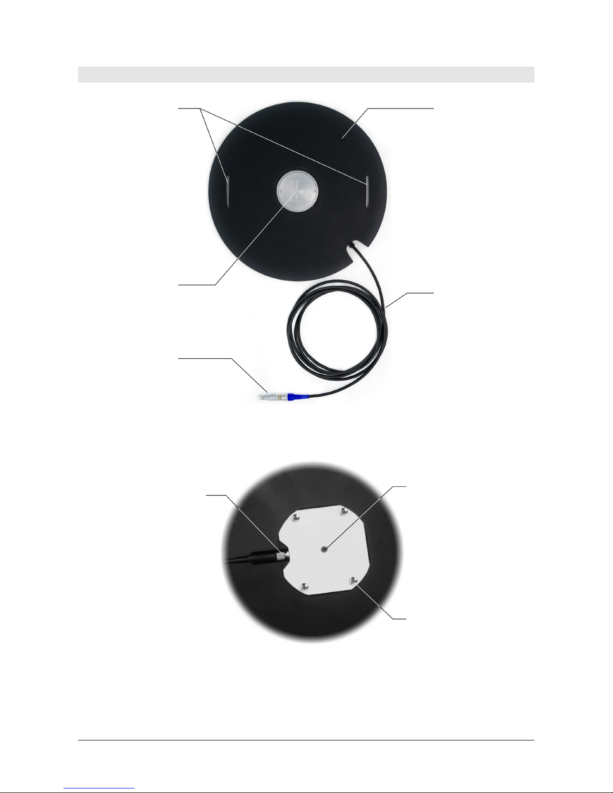
3 DESCRIPTION
Fig. 3.1: Top side
Fig. 3.2: Detail of bottom side
Rubber pad
HD2030.CAB3M-xM
cable
(optional)
Slots for the strap
(not supplied)
for fixing to the
back of the seat
Sensor
position
4-pole
connector
10-32 UNF
threaded hole
Screws for fixing
the
sensor to the
ru
bber pad
M5 connector

HD2030MSP - 6 - V1.0
4 USE
The rubber pad must be fixed to the seat or the backrest so that it is interposed between the seat itself and the body part subject to vibrations. For the fixing it is possible to use tape or a strap (not supplied), by passing it through the appropriat slots
provided in the pad.
The sensor detects the acceleration imparted to the body on three orthogonal axes. It
is necessary to accurately orient the axes of the accelerometer according to the reference system established by ISO 2631-1. The orientations of the axes along which the
sensor detects the acceleration are printed on the top of the accelerometer. The analog output signal corresponding to the X and Y axes increases when the sensor is subjected to an acceleration in the direction of the arrows printed on the housing. The
analog output signal corresponding to the Z axis increases when the sensor is subjected to an acceleration upwards.
Fig. 4.1: Reference axes of the accelerometer
The accelerometer is equipped with a male 4-pole M5 connector having the following
pinout:
Numero Pin Descrizione
1 …
2 …
3 …
4 …
Fig. 4.2: M5 connector pinout
Reference
axes
Reference

HD2030MSP - 7 - V1.0
For the connection to the HD2030 and HD2070 vibration analyzers, the optional
HD2030.CAB3M-xM cables can be used.
Route the connecting cable so that the connection point with the sensor is not subjected to stress. Minimize the possibility of cable movements, by securing it with cable
ties or tape. Do not route the cable near power lines, to avoid interferences on the
sensor output signal.
The accelerometer must be powered with constant current. Use only power
sources equipped with the current regulating function or use a current regulating diode as shown below:
Fig. 4.3: Sensor connection
If the accelerometer is connected to the HD2030 or HD2070 analyzer, the power supply and current regulation functions are performed by the analyzer.
In order to remove the bias voltage from the sensor output signal and obtain only the
AC component, connect the sensor output to the measuring instrument using a decoupling capacitor.
DO not power the accelerometer with voltage and corrente outside the limits
specified in the technical characteristics table, in order not to damage the internal electronic circuit.
Power supply
(18…28 V)
Measuring instrument
input
Accelerometer
GND
Decoupling
capacitor
Current regulating diode
(2…4 mA)

HD2030MSP - 8 - V1.0
5 FIXING FOR CALIBRATION
The accelerometer is supplied with a double threaded screw for fixing the sensor to
the vibrating base of a calibration system.
Fig. 5.1: Double threaded screw
The contact surface (vibrating base) of the sensor must be smooth and flat. Before
fixing the sensor it is advisable to clean the surface and apply a light film of grease/oil
(or equivalent fluid) to fill small gaps between the contact surface and the sensor and
improve the vibration transmissibility.
To fix the accelerometer using a screw it is sufficient a 1-2 Nm tightening force, compatible with a manual operation. For maximum measurements repeatability, the use
of a torque wrench is recommended.
As an alternative to screw mounting, in case the contact surface is not provided with a
threaded hole, it is possible to fix the sensor using:
adhesive material (double-sided tape, wax or quick glue);
a magnet.
Mounting with adhesive material or a magnet can reduce the sensor response to higher frequencies, especially in the mounting with magnet.
Mounting with adhesive material:
The sensor can be fixed with adhesive material to the contact surface:
directly;
through an adapter, fixing the sensor to the adapter (preferably using the screw)
and gluing the adapter to the contact surface.
If the sensor is fixed directly to the contact surface with glue or wax, be careful not to
obstruct the threaded hole at the bottom of the sensor; moreover, do not use too
much glue that could make the removal of the sensor difficult. In order to remove a
glued sensor, use a debonder product suitable for the type of glue used, avoiding to
force the sensor.
Sensor
Double threaded
screw
Vibrating base

HD2030MSP - 9 - V1.0
Fig. 5.2: Fixing with adhesive
Mounting with magnet:
Fix the sensor to the magnet (preferably using the screw) and place the magnet on
the contact surface.
Fig. 5.3: Fixing with magnet on a flat surface
For non-flat surfaces, dual-rail magnets can be used.
Fig. 5.4: Fixing with dual-rail magnet
For uneven surfaces, glue a flat metal base onto the surface, than place the sensor
with the magnet on the metal base.
Place the sensor with the magnet on the contact surface gently, to avoid damaging
the sensor due to the high accelerations caused by the magnet attraction.
Sensor
Double
threaded
screw
Adhesive
Adapter
Sensor
Double
threaded
screw
Magnet
Sensor
Dual-rail
magnet

HD2030MSP - 10 - V1.0
6 STORAGE
Storage conditions:
Temperature: -20...+60 °C.
Humidity: less than 90 %RH no condensation.
For storage, avoid places where:
There is a high level of humidity;
Instruments are exposed to direct sun radiation;
Instruments are exposed to a high temperature source;
There is vapor, salt and/or corrosive gases.
7 SAFETY INSTRUCTIONS
General instructions for safety
The transducer has been manufactured and tested in compliance with the safety standard EN61010-1:2010 “Safety requirements for electrical equipment for measurement,
control and laboratory use” and left the factory in a safe and secure technical condition.
The regular functioning and operational safety of the transducer can be ensured only if
all normal safety measures, as well as the specific measures described in this manual,
are followed.
The regular functioning and operational safety of the transducer can only be guaranteed under the climatic conditions specified in the manual.
Do not use the transducer in places where there are:
Rapid ambient temperature variations that may cause condensation.
Corrosive or flammable gases.
High-intensity electromagnetic fields, static electricity.
If the transducer is transported from a cold environment to a warm one, or vice versa,
the formation of condensation may cause disturbances to its functioning. In this case,
wait until the temperature of the transducer reaches room temperature before putting
into operation.
Obligations of the User
The user of the transducer must ensure compliance with the following standards and
guidelines for the treatment of hazardous materials:
EEC directives on workplace safety
National low regulations on workplace safety
Accident prevention regulations

HD2030MSP - 11 - V1.0
8 ORDERING CODES
HD2030MSP IEPE tri-axial accelerometer with rubber pad for the measurement of
the vibrations transmitted to the whole body by the seats to the occupants of vehicles. Sensitivity 100 mV/(m/s
2
). 4-pole M5 connector.
10-32 UNF mounting screw for the sensor calibration is included.
The HD2030.CAB3M-xM cable has to be ordered separately.
Accessories
HD2030.CAB3M-2M Cable for connecting the accelerometer to the HD2030 or
HD2070 vibration analyzer. M5 4-pole connector on the accelerometer side, circular 4-pole push-pull connector on instrument side. Cable length 2 m.
HD2030.CAB3M-5M Cable for connecting the accelerometer to the HD2030 or
HD2070 vibration analyzer. M5 4-pole connector on the accelerometer side, circular 4-pole push-pull connector on instrument side. Cable length 5 m.
Delta OHM LAT N° 124 metrology laboratories are ISO/IEC 17025 accredited by ACCREDIA in Temperature, Humidity, Pressure, Photometry/Radiometry, Acoustics and
Air Speed. They can provide certificates for the accredited quantities.
GUARANTEE
TERMS OF GUARANTEE
All DELTA OHM instruments are subject to accurate testing, and are guaranteed for 24 months from the
date of purchase. DELTA OHM will repair or replace free of charge the parts that, within the warranty
period, shall be deemed non efficient according to its own judgement. Complete replacement is excluded
and no damage claims are accepted. The DELTA OHM guarantee only covers instrument repair. The
guarantee is void in case of incidental breakage during transport, negligence, misuse, connection to a
different voltage than that required for the appliance by the operator. Finally, a product repaired or
tampered by unauthorized third parties is excluded from the guarantee. The instrument shall be returned
FREE OF SHIPMENT CHARGES to your dealer. The jurisdiction of Padua applies in any dispute.
The electrical and electronic equipment marked with this symbol cannot be disposed of in public
landfills. According to the Directive 2011/65/EU, the european users of electrical and electronic
equipment can return it to the dealer or manufacturer upon purchase of a new one. The illegal
disposal of electrical and electronic equipment is punished with an administrative fine.
This guarantee must be sent together with the instrument to our service centre.
IMPORTANT: Guarantee is valid only if coupon has been correctly filled in all details.
Instrument Code:
HD2030MSP
Serial Number
RENEWALS
Date
Date
Inspector
Inspector
Date
Date
Inspector
Inspector
Date
Date
Inspector
Inspector

GHM GROUP – Delta OHM | Delta Ohm S.r.l. a socio unico
Via Marconi 5 | 35030 Caselle di Selvazzano | Padova | ITALY
Phone +39 049 8977150 | Fax +39 049 635596
www.deltaohm.com | info@deltaohm.com
The quality level of our instruments is the result of the constant development of the product. This may
produce some differences between the information written in this manual and the instrument you have
purchased. We cannot completely exclude the possibility of errors in the manual, for which we apologize.
The data, images and descriptions included in this manual cannot be legally asserted. We reserve the
right to make changes and corrections with no prior notice.

GHM GROUP – Delta OHM | Delta Ohm S.r.l. a socio unico
Via Marconi 5 | 35030 Caselle di Selvazzano | Padova | ITALY
Phone +39 049 8977150 | Fax +39 049 635596
www.deltaohm.com | info@deltaohm.com
V1.0
06/06/2018
 Loading...