

Page 1
P.O. BOX 27
4300 AA ZIERIKZEE
NETH ER LANDS
TEL. +31 111 413656
FAX +31 111 416919
www.DeltaPowerSupplies.com
A mat ing con nec tor
with faston tabs is
packed with each
power sup ply
SX-SERIES EURO CAS SETTE SWITCHED MODE POWER SUP PLIES
With autoranging in put for worldwide use
The SX - series cov ers the whole out put volt age range be tween
3.5 V and 400 V DC.
75SX5
150SX5
75SX15-15 *)
150SX15-15
150SX75-75
150SX200-200
2x 6
2x 6
2x 15
2x 35
ST150
2x
*) op tion 2x 6-18 V 2 A is possible
3.5
3.5
3.5
6
-
6V 13 A
-
6V 26 A
-
15 V 2.5 A
-
15 V 5 A
-
75 V 1 A
-
200 V 0.3 A
-
615VV13
-
2.5AA
150SX15-15
For 24 V 2.5 A use 75SX15-15
For 24 V 5 A use 150SX15-15
For 24 V re dundant par al lel op er a tion
use 240S24 in stead of 150SX15-15.
The ST150 is a com bination of a 75SX5 and a
75SX15-15 in a 150 W case. The 5 V out put is iso lated
from the 2 x 15 V.
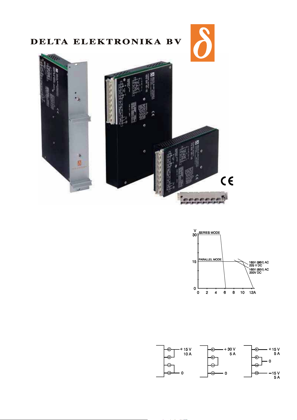
The units with two equal out puts can be used in three
dif fer ent modes, se ries-, par al lel- and dual-mode,
simply by con necting the out puts in se ries or par allel
at the mat ing con nector.
The two out puts can not be used sep arately.
Parallel mode Series mode Dual mode
150SX15-15
Page 2
DELTA ELEKTRONIKA BV SX-series
In dex of pos si ble volt age / cur rent com bi na tions
Volt age range
Max. cur rent Model
3.5 - 6 V 13 A 75SX5
3.5 - 6 V 26 A 150SX5
6 - 15 V 5 A 75SX15-15
6 - 15 V 10 A 150SX15-15
12 - 30 V 2.5 A 75SX15-15
12 - 30 V 5 A
150SX15-15
15 - 75 V 2 A 150SX75-75
30 - 150 V 1 A 150SX75-75
35 - 200 V 0.6 A 150SX200-200
70 - 400 V 0.3 A 150SX200-200
+ and – 6 to 15 V 2.5 A 75SX15-15
+ and – 6 to 15 V 5 A 150SX15-15
+ and – 15 to 75 V 1 A 150SX75-75
+ and – 35 to 200 V 0.3 A 150SX200-200
3.5 - 6 V 13 A
6 - 15 V 5 A
ST150
3.5 - 6 V 13 A ST150
12 - 30 V 2.5 A
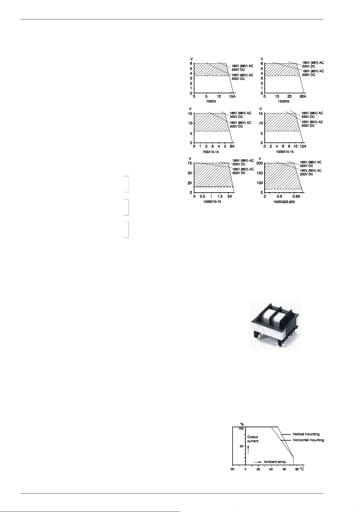
Derating of out put cur rent at low line volt age
3.5 - 6 V 13 A ST150
+ and – 6 to 15 V 2.5 A
Spec i fi ca tions:
In put : Autoranging
In rush cur rent limit : 10 A with NTC re sistor 30 Ohms
In su la tion
Input / output : 4 kVrms (1 min.), 8 mm creepage/cl.
Input / case : 2.5 kVrms (1 min.), 5 mm creepage/cl.
Output / case : 500 V DC, 1 mm creepage/clear ance
Safety : EN 60950 EN 61010
EMC : EN 61204-3 Power Sup ply Stan dard
Ef fi ciency : 84 % dual units, 80 % 5V units at 230 V AC in put.
Volt age reg u la tion : 5 and 15 V mod els 75 and 200 V mod els
Load 0 - 100% : 10 mV (with ext.sense) 200 mV
Line 185 - 264 V AC : 10 mV 150 mV
Ripple + noise : 5 mVrms, max. 20 mV p-p 70 mVrms, 100 mV p-p
Stability : 5.10
Temp. co ef fi cient : 1.10
Out put im ped ance : Max. 0.1 Ohm up to 100 kHz, except
Re cov ery time : 0.1 ms to re cover to within 0.1 V af ter a
Am bi ent tem per a ture : Stor age : −40 to + 85 °C
Temp. pro tec tion : Overtemperature pro tected.
AC 98 - 132 V 48 - 62 Hz 1.3 Arms 2.6 Arms Fuse 2 A T 4 A T
185 - 264 V 48 - 62 Hz 0.7 Arms 1.4 Arms
For DC op eration and op eration at 400 Hz con tact fac tory.
cold re sis tance.
1 kV DC for 150SX75-75 and 200-200.
EN 61000-6-3 (EN 55022B) Ge neric Emis sion
EN 61000-6-2 Ge neric Im mu nity
81 % and 78 % re spectively at 110 V AC in put.
–4
during 8 hours un der con stant con ditions after 1 hr warm up.
–4
per °C
150SX75-75 and 200-200 max. 1 Ohm.
50-100% load step. Max. de viation 0.4 V.
0.6 ms / 1.2 V for 75 V and 200 V mod els.
Op er at ing : −20 to + 50 °C, de rate current
linearly to 20% from 50 to 75 °C.
75 W 150 W 75 W 150 W
Transformer with split bob bin pro vides 4 kV
dielectric strength be tween in put and out put.
Tem per a ture de rat ing
Page 1 - 2 SPECIFICATIONS Rev. Nov. 2007
Page 3

SX-series DELTA ELEKTRONIKA BV
Hold-up time : 15 ms at full load, 30 ms at half load (220 V AC).
Se ries op er a tion : Up to 500 V total voltage. Up to 1 kV for 150SX75-75 and 200-200.
Par al lel op er a tion : Allowed up to 40 °C ambient temperature
Re dun dant par. op er a tion : Is pos si ble with ex ter nal di odes
Cur rent limit : The cur rent limit is fixed and pro tects the power supply dur ing over loading and short cir-
Volt age limit : For safety a second reg ulation circuit limits the out put voltage to about 10% above its
Volt age ad just ment : The out put voltage is con tinuously variable over the whole range with a 20 turn screw-
Re mote con trol : Volt age con trol with an ex ter nal po ten ti om e ter is pos si ble af ter some small in ter nal
Re mote pro gram ming : Remote pro gramming of the out put voltage is pos sible af ter chang ing an in ternal link on
Re mote sens ing : The sense points are in ternally con nected to + and – out put. These links have to be re-
Re mote Shut Down : By +5 V (3.5 - 12 V) be tween RSD and S– or –. Note: In dual mode S– is at neg.polarity.
Led lamp : A green led lamp at the front panel in dicates the out put.
MTBF : 1000 000 hrs
Dim. and weight : 75SX h
cuiting. Con tinuous over load and short circuit does not harm the unit.
10% more current can be taken at the low end of the voltage range.
range in case the nor mal reg ulation loop fails.
driver ad justment through the front panel.
changes (see manual page 3-2).
the PCB. An an alog volt age of 5 V be tween PROG. and S– corresponds with the max output voltage. Note: In dual mode S– is at a neg ative po larity.
moved when re mote sensing is re
SX15-15 and 0.5 V for SX5. How ever the voltage across the leads plus the load cannot
exceed the sup ply max. out put rating.
ST150, 150SX75-75 and 200-200 have no re mote sensing fa cility.
150SX h
x w x d = 100 x 35.5 x 172 mm, 0.6 kg
x w x d = 233.4 x 35.5 x 172 mm, 1.2 kg
quired. The max. sense range is 2 V per load lead for
75SX15-15 or 150SX15-15 used as dual power supply
Because the sense points of the reg ulation are in ternally con nected to the + and –15 V ter minals, the to tal volt ageV1 + V2 is
kept con stant.
WhenV1 and V2 are equally loaded the zero point will be in the
mid dle.
With un equal loads a slight zero shift will oc cur.
Asym met ri cal over load ing and shortcircuiting will not
damage the unit.
The 150
char ac ter is tics (rel a tively better).
SX75-75 and 200-200 have similar
Zero-shift caused by un equal load ing of the + and – 15 V
75SX5 150SX5 Units with two equal out puts:
use 2 pins use 3 pins
par al lel parallel Par allel mode Se ries mode Dual mode
Con nec tions SX-se ries
75SX5 75SX15-15 150SX5 150SX15-15 ST150
150SX75-75
150SX200-200
The H15 mat ing con nector (DIN 41612) is avail able
with faston tabs (stan dard), screw ter mi nals (op tional) and sol der pins (op tional)
The sense points S+ and S– are
internally con nected to + and –.
If re mote sens ing is re quired the
internal links have to be re moved
(not al lowed at 75 V, 200 V and tri ple units).
Bench adapt ers
BA 150
BA 150 can be used with:
150SX15-15, ST150
240S24
other 150SX op tional
BA 75 can be used with:
75SX5
75SX15-15
Rev. Nov. 2007 SPECIFICATIONS Page 1 - 3
Page 4

DELTA ELEKTRONIKA BV SX-series
Eurocard rack mounting
F8-6 for 150SX
F8-6T for ST150
F8-3
for
75SX
Wall and rail mount ing 75SX
Ver ti cal wall mount ing with W8-3 and CL15
Mount ing kit H95 for flat
wall mount ing
Flat wall mount ing with H95 kit and CL15
Rail mount ing with
W8-3, AR1 and CL15
Dimensions acc. to DIN 41494 to fit
into Eurocard racks 3U height
(132.5 mm) or 6U height (265 mm)
Adapters
W8-3 for ver tical wall or rail
mount ing 75SX
W8-6 for ver tical
mount ing 150SX
wall or rail
Wall and rail mount ing 150 SX, ST 150
Ver ti cal wall mount ing with W8-6 and CL15
Rail mount ing with
W8-6, AR1 and CL15
Clamp CL15 to fix the
H15 con nector when wall
mounted
Page 1 - 4 SPECIFICATIONS Rev. Nov. 2007
Adapter AR1 for
35 mm
Bracket H155 for flat
wall mount ing
Flat wall mount ing with 2 pcs H155 and CL15
 Loading...