

Page 1

796+<*;
4(5<(3
SM 6000 series
SM 15 - 400
SM 30 - 200
SM 45 - 140
SM 60 - 100
SM 70 - 90
SM 120 - 50
SM 300 - 20
SM 600 - 10
+,3;(,3,2;96502(
+*76>,9:<7730,:
Page 2

SM6000 DELTA ELEKTRONIKA BV
Safety Instructions
Caution
The following safety precautions must be observed during all phases of operation, service and
repair of this equipment. Failure to comply with the safety precautions or warnings in this document
violates safety standards of design, manufacture and intended use of this equipment and may
impair the built-in protections within. Delta Elektronika shall not be liable for user’s failure to comply
with these requirements.
Installation Category
The Delta Elektronika power supplies have been evaluated to installation category II (Over voltage
category II).
Grounding of Mains Input
This product is a safety Class 1 instrument. To minimize shock hazard, the instrument chassis
must be connected to the AC Power Supply mains through a three or four conductor power cable
for resp. a single or three phase unit, with the ground wire firmly connected to an electrical ground
(safety ground) at the power outlet.
For instruments designed to be hard-wired to supply mains, the protective earth terminal must be
connected to the safety electrical ground before another connection is made. Any interruption of
the protective ground conductor, or disconnection of the protective earth terminal will cause a
potential shock hazard that might cause personal injury.
Grounding of Power Output
If the output of a unit is specified to deliver max 60Vdc, and either the negative or positive power
output is grounded, the voltage on the following connections can be considered safe:
- power outputs and sense connections
- programming/monitor/status-signals, Interlock, Master/Slave-connections, ACF/DCF-relay
- all Delta Elektronika interfaces.
Warn ing:
When the pos itive power out put can ex ceed 60Vdc in re spect to the neg ative out put,
additional ex ternal mea sures must be taken to en sure safety iso la tion
- power out puts and sense con nections.
Warn ing:
When the neg ative power out put of the unit can ex ceed 60Vdc / 42.4Vpk in re spect to ground,
additional ex ternal mea sures must be taken to en sure safety iso la tion
- power out puts and sense con nections
-pro gram ming/mon i tor/sta tus-sig nals, In ter lock, Mas ter/Slave-con nec tions, ACF/DCF-re lay
-in ter faces with op er a tional iso la tion
- non-iso lated in ter faces.
of the following:
of the following:
Caution 1: If a low voltage unit has both power outputs floating, or if the output is in series with an
external high AC or DC voltage, the negative power output can exceed the safe value in respect to
ground as specified in the above warning!
Caution 2: Although a high voltage unit is set to a safe voltage below 60V, for safety it must always
be considered as high voltage unit! Wrong operation, a programming error or an external defect
can result in an unsafe high output voltage.
Caution 3: When programming a high voltage unit directly via a PC or via a network connection,
either ground the negative power output or use a safety isolated interface!
For more information and schematics regards Grounding and Safety, see the special application
note "Safe operation of a power supply" on the Delta Elektronika website.
Rev. Sept. 2012 SAFETY INSTRUCTIONS Page 2 - 1
Page 3

DELTA ELEKTRONIKA BV SM6000
Fuses
Fuses must be changed by authorized Delta Elektronika service personnel only, for continued protection against
risk of fire.
Input Ratings
Do not use an AC Supply which exceeds the input voltage and frequency rating of this instrument. The input
voltage and frequency rating of the Delta Elektronika power supply series are stated in de accompanying
datasheet.
Live Circuits
Operating personnel must not remove the instrument cover. No internal adjustment or component replacement is
allowed by non Delta Elektronika qualified personnel. Never replace components with the power cable
connected. To avoid injuries, always disconnect power, discharge circuits and remove external voltage sources
before touching components.
Parts Substitutions & Modifications
Parts sub sti tu tions and mod i fi ca tions are al lowed by au tho rized Delta Elektronika ser vice per sonnel only. For
repairs or mod ifications the unit must be re turned to a Delta Elektronika ser vice facility.
Removal of (safety) covers
Safety cover(s) are used to cover potentially hazardous voltages.
Observe the following when removing safety cover(s):
- Switch off the unit.
- Disconnect the unit from the mains supply.
- Wait for 3 minutes to allow internal capacitors to discharge.
- Unscrew the screws and remove the cover(s).
- Always place the cover(s) back before connecting the unit to the mains supply again.
Page 2 - 2 SAFETY INSTRUCTIONS Rev. Sept. 2012
Page 4
SM6000 DELTA ELEKTRONIKA BV
!
Environmental Conditions
The Delta Elektronika power supplies safety approval applies to the following operating conditions:
• Indoor use
• Ambient temperature : −20 to 50 °C
• Maximum relative humidity : 95%, non condensing, up to 40 °C
: 75%, non condensing, up to 50 °C
• Altitude: up to 2000 m
• Pollution degree 2
Caution risk of elec trical Shock
Instruction manual symbol. The instrument will be marked with this symbol when it is
necessary for the user to refer to the instruction manual
Pro tec tive ground con duc tor ter mi nal
Off (sup ply)
o
I
On (Sup ply)
Canada
This product has been tested to the requirements of CAN/CSA-C22.2 No. 61010-1, second edition, including
Amendment 1, or a later version of the same standard incorporating the same level of testing requirements
WEEE
(Waste Electrical & Electronic Equipment)
Correct Disposal of this Product
Applicable in the European Union.
This marking shown on the product, its packing or its literature indicates that
it should not be disposed with other wastes at the end of its working life, but
should be collected separately to recycle it responsibly to promote the
sustainable reuse of material resources.
Rev. Sept. 2012 SAFETY INSTRUCTIONS Page 2 - 3
Page 5

SM6000 DELTA ELEKTRONIKA BV
DESCRIPTIONS
1) OUT PUT
The SM15-400, SM30-200, SM45-140, SM60-100, SM70-90, SM120- 50,
SM300-20 and SM600-10 can ei ther be used as a con stant volt age source
with current limiting or as a con stant cur rent source with voltage lim iting.
The change of mode oc curs sharply at the cross ing of the voltage and cur rent
set tings. Figure 3 - 1 shows the out put ranges.
• DISPLAY CV/CC SETTINGS FUNCTION
The settings of the voltage and cur rent con trol (also when pro grammed) can
be ob served on the front panel me ters by press ing the Dis play CV/CC Set tings button. This al lows the current limit to be set when op erating in the CV
mode with out shorting the out put terminals, and the volt age limit to be set
when op erating in the CC mode without open ing the load leads.
• OVER LOAD PRO TEC TION
The power supply is fully pro tected against all overload con ditions, in cluding
short cir cuit.
IN PUT VOLT AGE
2)
The power supplies have a wide in put voltage range.
• The unit needs a 3 phase in put voltage, but no neu tral con nec tion is re -
quired.
• The unit only op erates on three phases. In case of Phase Loss, the
ACF-status (AC Fail) will be high, the ACF-LED will light and the out put
shuts down after a few sec onds.
IN PUT CUR RENT
3)
The unit has ac tive power fac tor cor rection (PFC). The in put cur rent will
therefore al most be a sine wave. This means that the RMS-value and the
harmonic dis tortion of the in put cur rent will be relatively low.
The peak in rush current is electronically lim ited. Switching on and off re peatedly will not result in excessive currents like with NTC cir cuits.
SM 15-400
SM 45-140
SM 70-90
SM 300-20
SM 30-200
SM 60-100
SM 120-50
SM 600-10
4)
STANDBY IN PUT POWER
The unit consumes very lit tle power when in standby. This makes it possible
to leave the in put power on when the out put is disabled us ing the Output
On/Off push but ton on front panel or the Re mote Shut Down in put (pin 5 on
connector CON E on the rear panel).
5)
EFFICIENCY
The ef ficiency is very high and constant over a wide output cur rent range.
High ef ficiency means low power loss and low heat gen eration.
CV REG U LA TION
6)
The spec ified CV-load reg ulation value is mea sured di rectly on the out put
terminals. This is be cause at high current, a few cm of ca ble can have a voltage drop of several mV.
CC REG U LA TION
7)
For ac curate CC-load reg ulation, do not use ex ternal volt age sens ing.
A volt age be tween S- and minus out put will create an er ror of about 0.04 %
per volt.
A volt age be tween S+ and + is not crit ical.The CC-stability is also af fected by
ex ter nal volt age sens ing.
Note: when the unit op erates in CC-mode, the DCF-LED will be on. When
the unit is in CC-mode most of the time, it is possible to dis able the LED with
DIP switch 3 on SW1 (rear panel).
RIPPLE & NOISE
8)
The out put rip ple is very low with al most no spikes. The spec ified rip ple volt -
age is mea sured di rectly on the out put terminals us ing a probe with very short
connections. This to avoid pick up of mag netic fields, see fig. 3 - 2 and fig. 3 -
3.
At low tem per a tures like -20°C the rip ple in creases. By us ing high qual ity
elec tro lytic ca pac i tors the in crease is rel a tively low.
fig. 3 - 2
Mea sur ing rip ple volt age
WRONG !
fig. 3 - 3
Mea sur ing rip ple volt age
RIGHT !
Rev. Sept. 2012 DESCRIPTIONS Page 3 - 1
Page 6

DELTA ELEKTRONIKA BV SM6000
V
A
Imon
0-5V
Vmon
0-5V
Return of
ref, prog, mon.
9) AN A LOG PRO GRAMMING
The out put voltage and cur rent can be programmed by an ex ternal an alog
voltage. This pro gramming is very ac curate and lin ear. The lev els are all
standardized on 5 V.
Standard the SM300-20 and SM600-10 are equipped with the ISO-AMP,
see next paragraph.
For the other units, the in puts have a protection circuit formed by a series
re sis torand a par al lel zener (see fig. 3 - 4). The ca pacitor limits the speed
to a safe value. Note that the an alog in puts (and outputs) are not float-
ing, but the common is connected to the negative output terminal.
Wrong con nec tion of Ø can cause earth loops which can trip the fuse. After re moving the fault, the fuse will re set (PTC-fuse). For iso lated pro gramming see next para graph.
10)
ISO LATED AN A LOG PRO GRAMMING
To pre vent earth loops which can cause pro gramming er rors, use an iso lated pro gramming source. If this is not pos sible, use the op tional ISO
AMP CARD
With the ISO AMP CARD earth loops be tween the unit and the pro gramming source are prevented.
ETH / IEEE488 / RS232 / CAN / PROFI PRO GRAM MING
11)
The Delta Elektronika PSC-ETH, PSC-488, PSC-232, PSC CAN and
PSC PROFI con trollers can be factory in stalled in side the unit.
Voltage and cur rent can easily be pro grammed and read back. Also all
the status outputs can be read by the computer.
(δ-prod uct) which can be built in side the unit.
Pro gram ming in puts (in ter nal cir cuit)
fig. 3 - 4
12)
MON I TORING OUT PUTS
The mon itor outputs give a voltage 0 - 5 V pro portional to the out put cur rent or voltage. The output cur rent can eas ily be mea sured us ing the
I-mon i tor (see fig. 3 - 6). The mon itor outputs are buffered with op-amp’s
and pro tected with se ries re sistors and parallel zeners (see fig. 3 - 7). The
table in fig.3 - 5 shows the impedance lev els of the mon itoring out puts.
For us ing Imon on a pul sating load, see paragraph 20) of this chap ter.
13)
+12 V ON PRO GRAMMING CON NECTOR
The +12 V on the pro gramming con nector can be used to sup ply ex ternal
circuits. The out put is current limited, but should not be overloaded. The
fuse F27_3 on P598 could blow. The fuse F27_3 also protects the in ternal
circuit, in case an ex ternal high volt age is ap plied by ac cident. Note: this
fuse is a special 600 V type, al ways re place with the same type.
STATUS OUT PUTS
14)
All the status outputs are logic out puts. Logic "0" means the out put is 0 V,
logic "1" means the out put is 5 V (Ro = 500 Ohm). This makes it pos sible
to drive directly: an opto-coupler, a TTL gate or a CMOS gat e.
The Limit Sta tus or LIM-status is "1" in case the out put voltage or cur rent
reaches the limit setting. Which limit cir cuit is ac tive can be seen on the
front panel LED’s.
The Over Tem per a ture Sta tusor OT sta tus is "1" in case of an over tem-
per a ture, the OT LED will be on and the output shuts down. As a
pre-warning theOT LED starts to blink when the unit runs hot but the situation of over tem perature is not reached yet. The status will s till be low
when the LED is blink ing.
pin De scrip tion, see par.12)...17) for details
1Ø, re turn of ref erence, prog. in puts and
monitor outputs (Ro = 1.2 Ohm).
2 current mon itor output 0 - 5 V
(Ro = 1.2 Ohm, Io max = 4 mA)
3 current pro gramming in put (0 - 5 V),
Ri = 8 MOhm
4 CC sta tus output, logic 1 = CC mode
(5 V / 500 Ohm)
5 Re mote ShutDown (4 - 12 V),
Ri = 5 kOhm
6 PSOL sta tus output, logic 1 = PSOL
(5 V / 500 Ohm)
7 +12 V output
(Ro = 3 Ohm, Io max = 0.2 A)
8Ø, re turn of sta tus outputs, +12 V
and Remote ShutDown
9ref er ence volt age 5.1 V
(Ro = 1.2 Ohm, Io max = 4 mA)
10 voltage mon itor output 0 - 5 V
Ro = 1.2 Ohm, Io max = 4 mA)
11 voltage pro gramming in put (0 - 5 V)
Ri = 8 MOhm
12 OT - sta tus output, logic 1 = OT
(5 V / 500 Ohm)
13 LIM - status output, logic 1 = LIM
(5 V / 500 Ohm)
14 DCF - sta tus output, logic 1 = DCF
(5 V / 500 Ohm)
15 ACF - status output, logic 1 = ACF
(5 V / 500 Ohm)
fig. 3 - 6
us ing mon i tor out puts
Page 3 - 2 DESCRIPTIONS Rev. Sept. 2012
Ex ter nal me ters
Buf fered mon i tor out puts
fig. 3 - 7
fig. 3 - 5
Con nec tions AN A LOG PROG. CONNECTOR
Page 7

SM6000 DELTA ELEKTRONIKA BV
fig. 3 - 8 Location of out put terminals and an alog prog. con nector on rear panel
CON A In ter lock Con nec tor
CON B Master connector for Mas ter / Slave op eration (out put)
CON C Slave con nector for Mas ter / Slave op eration (in put)
CON D Relay Out puts, con tacts 1 - 6
CON E An a log Pro gram ming Con nec tor
( not avail able on SM300-20 / SM600-10, see CON H)
CON F PSC-232, from PC or pre vious PSC (op tional)
CON G PSC-232, to next PSC (op tional)
CON H PSC-488 (op tional) or ISO AMP CARD (op tional)
SM300-20 / SM600-10 stan dard with ISO-AMP in stead of CON E.
SW 1 Var i ous set tings, see para graph 16)
SW 2 Set tings for PSC-488 and PSC-232 (op tional) or
fig. 3 - 9 Connectors and switches on the rear panel
The Cur rent Con trol Status or CC-status out put is "1" when the unit is in
CC-mode.
The Power SinkOver Load Sta tus or PSOL-status out put is "1" when the op tional
Power Sink is over loaded or over heated.
The AC-Fail Sta tus or ACF-sta tus out put is "1" in case of Phase Loss or when the
input voltage is be low 340 V.
The DC-Fail Sta tus or DCF-sta tus out put is "1" when the out put voltage is ei ther
5% be low or above the set point.
When the unit is in CC-mode,DCF will al ways be "1", see pre vious para graph7).
fig. 3 - 10
15)
STATUS RE LAY OUT PUTS
The power supply has 2 status re lay out puts, with each a c hange-over contact .
They are connected to con nector CON D. The pins 1,2,3 are con nected to the
DCF-relay and pins 4,5,6 to the ACF-relay (see fig. 3 - 10).
FUNCTION SWITCHES ON SW1
16)
In the following ta ble the functions of the DIP switches 1-5 of switch SW1 at the
rear side are ex plained:
Status relay outputs on CON D.
This sit uation gives the relay
po si tions dur ing fault con di tion.
Switch no. UP po si tion DOWN po si tion De fault Set ting
SW 1 - 1 Programming via 15pole con nec-
tor CON E (an alog).
Op tional pro gram ming with e.g.
PSC-232,PSC-488, ISO AMP CARD
Up
SW 1 - 2 ‘Output On’ af ter mains on ‘Output Off’ af ter mains on Down
SW 1 - 3 DCF LED enabled DCF LED dis abled (DCF sta tus and
Up
DCF re lay are still en abled)
SW 1 - 4 Parallel Mas ter / Slave operation Series Mas ter / Slave operation Up
SW 1 - 5* After switch ing mains on, the unit
will start with the same set tings
for the volt age and the cur rent as
it had be fore switch ing mains off
After switch ing mains on, the unit will
always start up with a volt age set ting
of 0 V and a cur rent set ting of 0 A.
Once the unit is switched on, the volt -
Down
age and cur rent can be set to the pre -
ferred value.
* = SW1-5 only on SM300-20 / SM600-10 and on units with op tional dig ital encoders (op tion P220).
Rev. Sept. 2012 DESCRIPTIONS Page 3 - 3
Page 8

DELTA ELEKTRONIKA BV SM6000
17) RE MOTE SHUT DOWN (RSD)
A volt age of +4 V...+12 V on the Re mote Shut Down in put on the
programming con nector CON E will switch off the out put of the unit.
It is also pos sible to use a re lay con tact or a switch to shut the unit
down (see fig. 3 - 11).
In standby mode the power sup ply con sumes very lit tle power.
18)
IN TER LOCK
The In terlock con nector (CON A, rear panel) has 2 in puts which
have to be con nected together to turn on the out put of the unit.
As soon as the link be tween the 2 in puts of the In terlock con nector
is dis rupted, the out put of the unit shuts down.
It can be used in com bination with a cab inet door con tact (safety
precaution) or as an emer gency break t o stop a mo tor which is
powered by the unit.
In case the link is dis rupted the RSD LED will light. In contrast with
Re mote Shut Down, also the DCF LED will be on, the DCF status
will be high and the re lay con tact will change.
Once the in puts are connected again, the out put will be on.
No volt age may be ap plied to the pins in the Interlock connector.
PRO GRAMMING SPEED
19)
The rise and fall time is mea sured with a step wave form at the CV
prog. in put. P rogramming from a low to a high output voltage is
nearly load in dependent, but pro gramming down to a low voltage
takes more time on lighter loads. This is caused by the out put ca pacitors, which can only be discharged by the load be cause the
power sup ply can not sink c urrent. With the Power Sink op tion,
also the pro gramming down speed is nearly load in dependent.
When hav ing a unit with a fast pro gram ming op tion, the rise and
fall time is 5 to 25 times faster (see datasheet). The pro gramming
source must be floating or oth erwise an ISO AMP CARD must be
used, a non-floating source will re sult in slope dis tortion.
When us ing fast pro gramming it is gen erally not recommended to
usere mote sens ing orse rial /par al lel op er a tion. Con sult fac toryfor
advice. Note that the output rip ple is higher.
Re mote Shut Down us ing a relay contact
fig. 3 - 11
fig. 3 - 12
Pulsating load current
PUL SATING LOAD
20)
To avoid overheating the out put ca pacitors, the AC component of
the load cur rent should be limited (see fig. 3 - 12).
One method of de creasing the AC current through the output ca -
pac i tor is by us ing a large ex ter nal elec tro lytic ca pac i tor in par al lel
with the load. Care must be taken so that the ca pacitor in combination with the lead in ductance will not form a series resonant cir cuit!
When us ing re mote sens ing on a pul sating load (for in stance a
DC-motor), use a ca pacitor in se ries wit h a re sistor over the load
(see fig. 3 - 13). Like this the AC-component caused by the pul sating of the load is fil tered.
Note: in case of a pul sat ing load, the I mon itor voltage will not ex actly match the out put cur rent. This is mainly caused by the current
through the out put ca pacitors. Re mote sensing will worsen this ef fect.
IN SU LA TION
21)
For safety the in su la tion of the sep a rat ing com po nents (trans form -
ers) be tween in put and out put is tested at 3750 Vrms dur ing 1 min ute. This is tested be fore as sembly.
Warn ing! The 3750 Vrms can not be tested af terwards on the
as sem bled unit be cause the in su la tion be tween the com po nents
on the in put side to the case (like the bridge rec tifier) is spec ified at
2500Vrms. Sincethe in su la tion out put-caseis low(only 600 VDC)
the in sulation of the pri mary components to case will break down
when 3750 Vrms is ap plied be tween in put and out put (2500 Vrms +
600 VDC < 3750 Vrms) (see also fig. 3 - 14).
Note: when testing the in sulation, take care t o charge and dis charge the capacitors be tween in put - case and out put - case
slowly (e.g. in one sec ond). This to prevent high peak currents,
which could de stroy the power sup ply. Make sure to discharge the
ca pac i tors com pletely be fore us ing it again.
fig. 3 - 13
Remote sensing on a pulsating load
fig. 3 - 14
In su la tion test voltages
Page 3 - 4 DESCRIPTIONS Rev. Sept. 2012
Page 9
SM6000 DELTA ELEKTRONIKA BV
22) RFI SUP PRES SION
Both the in put and out put have RFI fil ters, re sulting in very low
conducted RFI to the line and load. Due to the out put fil ter the
output voltage is very clean, hav ing al most no spikes.
23)
OP ER ATING TEMP
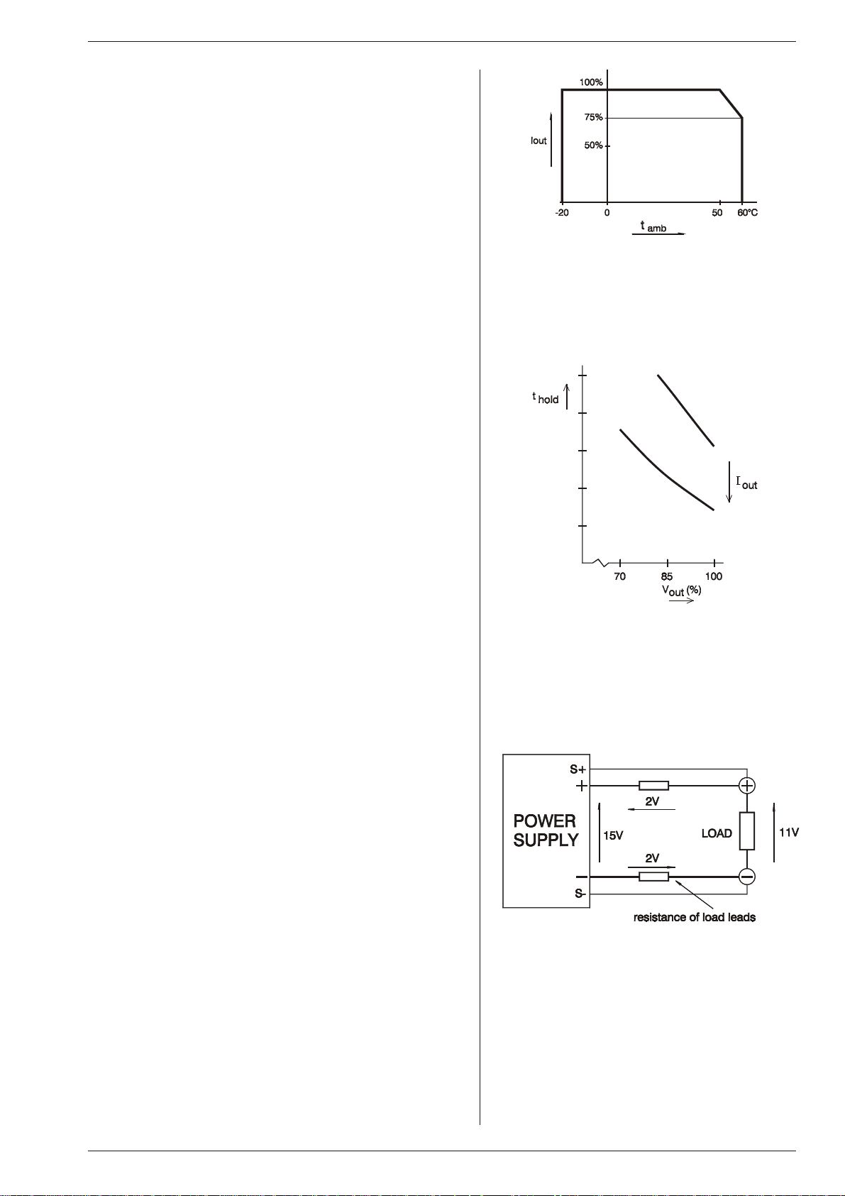
At full power the op erating tem perature range is –20 to +50 °C.
From 50 to 60 °C the output cur rent has to be de rated lin early to
75 % at 60 °C (see fig. 3 - 15). These tem peratures hold for nor mal use, i.e. the ven tilation open ings on the left and right side
must be free.
fig. 3 - 15
THER MAL PRO TEC TION
24)
A ther mal switch shuts down the out put in case of in sufficient
cool ing.The OT sta tus will be high. Af ter cool ing down the unit
will start work ing again.
TheOT-LED on the front panel will be on and the OT-status sig nal will be "1" in case of a tripped ther mal pro tection.
As a pre-warning the OT-LED blinks (sta tus will still be low), this
will start be fore the power sup ply shuts down.
HOLD - UP TIME
25)
The hold - up time de pends on the load and the out put voltage.
A lighter load or a lower output voltage re sults in a lon ger hold up time (see fig. 3 - 16).
Op er ating tem per a ture ranges
TURN ON DE LAY
26)
The out put voltage is avail able about 0.2 sec af ter mains switch
on.
IN RUSH CUR RENT
27)
The in rush cur rent is elec tron i cally lim ited.
Repeatedly switching on and off does not change the max imum
peak cur rent.
Switching on and off at a fast rate can overheat the in rush current limiter. With the re sult that the unit does not start any more.
After cool ing down (mains switched off) it will be OK again.
PHASE LOSS
28)
Phase loss means that not all three phases are available.
The ACF-status will be high, the ACF LED will light and the
output of the unit will shutdown af ter a few seconds.
RE MOTE SENSING
29)
The voltage at the load can be kept con stant by re mote sensing.
This feature is not rec ommended for normal use but only when
the load voltage is not al lowed to vary a few millivolts. Al ways
use a shielded ca ble for sensing.
In or der to compensate for the voltage drop across the load
leads, the unit will have to sup ply a higher voltage (see fig. 3 -
17):
Uout = (volt age drop across each lead) + (voltage across the load).
Hold-up time vs V
fig. 3 - 16
with I
out
as a pa ram e ter
out
The voltage limit reads the voltage di rectly at the out put ter minals. The set ting for the limit must therefore be in creased by the
total voltage drop across the load leads.
The voltage dis play on the front panel and the volt age mon itor
output on CON E are con nected to the sense leads and there fore read the volt age across the load and not the voltage on the
out put ter mi nals.
The sense leads are pro tected against ac ci den tal in ter rup -
tion. The max imum voltage be tween the output terminals and
the sense in puts is limited at 2.5 V.
For sensing on a pul sat ing load see para graph 20) of this
chap ter.
Rev. Sept. 2012 DESCRIPTIONS Page 3 - 5
Remote sensing, voltage drop in load leads sub -
fig. 3 - 17
tracts from max. output
Page 10

DELTA ELEKTRONIKA BV SM6000
30) SERIES OP ER A TION
Series op eration is al lowed up to 600 V total voltage. The power sup plies can
be con nected in se ries without spe cial pre cautions.
For eas ier con trol, Mas ter / Slave op eration is recommended (see fig. 3- 18).
By us ing the Mas ter / Slave se ries fea ture a dual tracking power sup ply can
be made with one unit as mas ter and one as slave.
For se ries op er a tion in com bi na tion with Power Sink op tion, all units must
have a Power Sink built in side oth erwise no power can be ab sorbed.
31)
PAR AL LEL OP ER A TION
Paralleling of the units has no limitations. The power supplies can be con nected in par allel with out spe cial pre cautions. For eas ier con trol, Mas ter /
Slave op eration is recommended (see fig. 3- 18 and fig. 3 - 19).
Nor mal par al lel op er a tion of Fast Pro gram ming units can give prob lems,
each com bination has to be tested first, in com bination with the load !
For par al lel op er a tion in com bi na tion with Power Sink op tion, only one unit
can have a Power Sink. Re fer to Power Sink man ual for de tails and
restrictions.
MASTER / SLAVE OP ERATION
32)
The Mas ter / Slave fea ture makes it pos sible to use the power sup plies as
building blocks to form one large unit (see fig. 3 - 19).
Mixed par allel - se ries op eration is also pos sible, to a maximum of 600 V.
The re sulting com bination of units be haves like one power sup ply and can be
manually con trolled or pro grammed on the mas ter. Figure 3 - 20 shows a
com puter con trolled Master / Slave par al lel com bi na tion.
Connect the dif ferent units with standard RJ45 ca bles (see fig. 3 - 21), us ing
CON B and CON C on the rear side. With DIP switch 4 of switch SW1 the Par allel or Se ries mode can be se lected.
The slaves will fol low the master. The re sult is true current or voltage shar-
ing in the par allel or se ries mode respectively.
Mas ter / Slave se ries op er a tion
Master / Slave parallel operation
fig. 3 - 18
fig. 3 - 19
Note: Master / Slave parallel op eration is not recommended for more
than 3 units or in combination with Fast Pro gramming option.
Consult factory for a so lution.
fig. 3 - 20
The Master / Slave combination can also
be pro grammed with the interfaces
PSC-488 or the PSC-232
fig 3 - 21
Use standard UTP cables (RJ45) for Mas ter / Slave operation
Page 3 - 6 DESCRIPTIONS Rev. Sept. 2012
Page 11

SM6000 DELTA ELEKTRONIKA BV
33) VOLTAGE AND CUR RENT LIMIT
The Voltage Limit will pro tect your circuit from un wanted high voltages. A high
out put volt age couldbe caused by ac ci den tal in ter rup tion ofleads, ac ci den tally
turning up the voltage potmeter, a pro gramming er ror or a de fect in the power
supply. The Volt age Limit circuit uses a sep arate voltage di vider con nected di rectly to the output terminals.
The Cur rent Limit pro tects your circuit from un wanted high cur rents.
The Voltage and Cur rent Limits maintain the output to a safe pre set value.
They do not trip, so no re setting is needed after a fault. It can be very handy to
have hard ware lim its when the power sup ply is pro grammed.
The lim its can easily be set by press ing the DISPLAY LIMITS but ton and ad justing the potentiometers with a screwdriver. The LED’s next to the potmeters
indicate the ac tivity of each limit, also the LIM-status out put will be "1".
34)
PO TEN TI OM ETERS AND ENCODERS
At the front panel, standard ev ery unit is equipped with knobs for the CV and
CC con trols and with screwdriver ad justment for the Voltage and Cur rent Limit.
The SM300-20 and SM600-10 have digital encoders for the CV/CC-controls,
with a very long life time and in telligent functions such as vari able coarse/fine
pitch ad justment, lock ing of CV/CC-settings and a selectable start-up voltage
(start at 0V/0A or at last settings).
The lower voltage units have an alog po tentiometers for the CV/CC-controls .
Optional they can be equipped with screwdriver ad justment for
CV/CC-settings at the front panel or also with dig ital encoders (op tion P220).
See fig. 3 - 22 for op tion P001.
COOLING
35)
Two low noise blowers cool the unit. The speed of the fans de pend on the tem-
per a ture of the in ter nal heatsink . Normally at 50 °C am bient and full load the
fan will not work at full speed.
A spe cial fea ture is that the fans blow through a tun nel where the heatsinks are
situated, the del icate con trol circuitry is sep arated and will not be in the air flow
path (see fig. 3 - 23).
Because the air en ters at the left and ex its at the right side, it is pos sible to stack
the power sup plies, no distance be tween the units is re quired. Only the ven tilation open ings at the left and right side should be free.
For long life the temperature of the air en tering on the left side, should be be low 35 °C un der nor mal con ditions. Un der ex treme conditions it should be be low 50 °C.
Note: The con trol circuit makes the fan start in a pul sating mode, during which
period it can pro duce a high pitched sound. This is nor mal.
DI MEN SIONS
36)
fig. 3 - 22
Screwdriver ad justment at front panel
fig. 3 - 23
The two fans blow through the tun nels,
where the heatsinks are situated
Rev. Sept. 2012 DESCRIPTIONS Page 3 - 7
Page 12

DELTA ELEKTRONIKA BV SM6000
OPERATING MANUAL
1) OPERATING THE UNIT FOR THE FIRST TIME
Warn ing: care fully read the chap ter "Safety In structions"
in this man ual be fore op erating the unit!
• Check there is no con densation on the unit. If there is, al low some
time to dry.
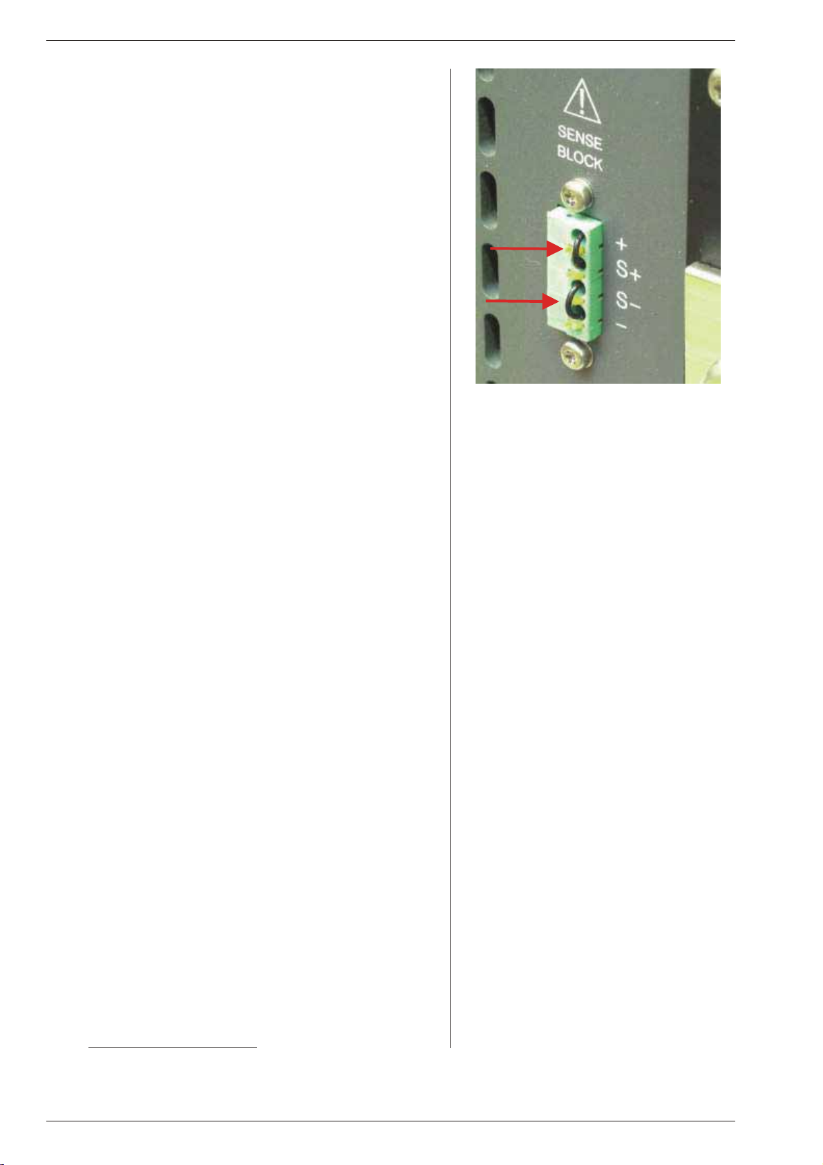
• Check there is a link be tween + and S+ and be tween – and S– on
the SENSE BLOCK (on rear panel).
• Check there is a link be tween the in puts of the In terlock (CON A).
• Set the CV and CC po tentiometers to min imum (fully anti clock-
wise). For units with Option P220, this is not needed. These units
are set to start at 0 V - 0 A when op erated for the first time.
• For the in put power, con nect a ca ble of 4-wires of 2.5mm
torque of 0.6Nm to fas ten the screws on the in put con nector.
• For the out put power, see ta ble 4 - 1 for ca ble di am e ters and
mounting torque .
• Withhigh out put current make sure to use low resistive con nec-
tions be tween the power sup ply and the load:
- Mount the ca ble lugs di rectly
on the tinned output strips
fol lowed by a washer, a split washer and a nut (see fig. 4 - 1).
Al ways in this or der!
- Never place wash ers be tween the lugs and the strips
be cause this can re sult in excessive heat!
- Only use nuts and wash ers sup plied with the unit.
• Switch on unit.
• Disable the Key lock function, see next para graph 2) .
• Check the unit is not in Re mote CV or Re mote CC (LED’s for this
function should be off). Press the RE MOT E/LOCAL but ton un til
both LED’s are off.
• Turn on the out put by pressing the OUTPUT ON/OFF but ton.
• Turn both the CV and CC po tentiometer a few turns clockwise.
A volt age should now be pres ent on the output.
• By pressing the DISPLAY CV/CC SETTING button the m eters
will show the setting of the CV and CC po tentiometer.
• By pressing the DISPLAY LIMITS but ton the voltmeter will show
the setting of the CV-limit and the CC-limit potentiometer.
• Check that the cool ing of the unit is not ob structed.
2
. Use a
fig. 4 - 1
Low re sis tive ca ble con nec tion by mount ing the
cables di rectly on the tinned out put strips
Unit Ca bles
[mm2]
SM15-400 150 M12 80
SM30-200 70 M10 40
SM45-140 35 M10 40
SM60-100 35 M10 40
SM70-90 25 M10 40
SM120-50 10 M8 20
SM300-20 4 M8 20
SM600-10 2.5 M8 20
Bolts Torque
[Nm]
ta ble 4 - 1
Ca ble di am e ters and torque
KEY LOCK
2)
• If the func tion KEYLOCK is activated, it is no lon ger pos sible to
operate the REMOTE/LOCAL but ton and the OUTPUT ON/OFF
button. This func tion can be use ful to protect the out put from ac cidental shutdown. The function KEYLOCK does not in fluence the
operating of the CV, CC, CV-limit and CC-limit po tentiometers.
• Units with dig ital encoders:
For SM300-20 / SM600-10 and units with Op tion P220, also the
digital encoders for CV and CC are dis abled with the Keylock
function. This means settings of the voltage and cur rent do not
change when the encoders are op erated. It is still pos sible to op er ate the an a log CV-limit and CC-limit po ten ti om eters.
• Ac ti vate Key lock:
Pressing the but tons DISPLAY SETTINGS and DIS PLAY
LIMITS at the same time for more than 3 seconds, ac tivates the
function KEYLOCK. The mo ment this func tion is activated, the
LED’s for RE MOTE CV / CC and for OUTPUT ON will blink a few
times.
• Dis able Key lock:
Pressing the same buttons again for 3 sec onds, dis ables the Keylock function. The LED’s for RE MOTE CV / CC and for OUTPUT
ON will blink again to in dicate the new set ting.
3)
SELECT START-UP MODE
The be low is only ap plicable for SM300-20 / SM600-10 and units
with mag netic encoders - op tion P220.
• Setting switch SW1-5 at the rear panel in po sition DOWN, the unit
will al ways start at 0V / 0A after mains switch on.
• Setting switch SW1-5 in po sition UP, the settings after mai ns
fig. 4 - 2
Pro gram ming by volt age:
left voltage -, right current pro gramming
fig. 4 - 3
Pro gram ming by cur rent
left voltage -, right current pro gramming
Page 4 - 1 OPERATING MAINTENANCE TROUBLE SHOOTING CALIBRATING Rev. Sept. 2012
Page 13

SM6000 DELTA ELEKTRONIKA BV
switch on will be the same as be fore switching the mains volt age
off.
4)
AN A LOG PRO GRAMMING
• Set DIP switch 1 of SW1 in po sition UP to se lect CON E for pro-
gramming. For SM300-20 / SM600-10 see para graph ISO-AMP.
• Dis able Key lock.
• Set the unit in RE MOTE CV for volt age pro gramming and/or in
REMOTE CC for cur rent pro gramming.
Use the RE MOT E/LOCAL but ton and push this but ton sev eral
times un til the right setting is activated.
Note that pushing the RE MOTE/LOCAL but ton will shutdown the
output to avoid ac cidental dam age to the load.
• Connect the pro gramming voltage source(s) (0 - 5 V) to the an a-
log pro gramming con nector CON E on the rear panel (see fig.
4 - 2 and fig. 4 - 3). Al ways use a shielded ca ble (max. 30 me ter)
fig. 4 - 4
Re mote con trol
for pro gram ming.
• Turn the out put on again with the OUTPUT ON/OFF but ton.
• If only the voltage is pro grammed, the max imum current can still
be set with the CC knob on the front panel and vice versa. If this is
not de sirable the unit can be or dered with Option P001 or Option
P220 in or der to have a fixed set ting for the CV and the CC knob
on the front panel, see also par. 34) in pre vious chap ter "De scriptions".
• To avoid hum or noise, the pro gramming ca ble may have t o be
twisted in some cases.
• To pro gram the unit by current in stead of volt age, sim ply use a
parallel re sistor as a current to volt age con verter.
• Pressing the DISPLAY SETTINGS but ton will show the pro -
grammed values for CV and CC.
• CAU TION: The an alog in puts are not iso lated from the out put.
The Ø of the prog. in put (pin 1) is in ternally con nected to the S–,
the S– is connected to the neg ative output. To pro tect the in ternal
fig. 4 - 5
Lo cal sens ing
wiring a 650 mA self-resetting fuse is con nected in se ries (F27_1
on P598). To avoid earth loops, use an isolated pro gramming
source. If this is not pos sible, see nest para graph 5) for us ing the
op tional ISO AMP CARD.
ISO LATED AN A LOG PRO GRAM MING
5)
• For pro gramming via the ISO AMP CARD, set DIP switch 1 on
SW1 in the po sition DOWN.
• When the ISO AMP CARD is built in side the unit, CON E has been
removed. Use CON H in stead. The pin ning of CON H is equal to
the pin ning of CON E .
• For fur ther op er at ing in struc tions, see pre vi ous para graph 4).
IEEE488 / RS232 PRO GRAMMING
6)
• Set DIP switch 1 on SW1 in po sition DOWN for programming with
thePSC-488 us ing CON H or programming with the PSC-232 us ing CON F and G. With DIP switch 1 in this
po si tion, the sig nals Vprog (pin 11) and Iprog (pin 3) are
disabled on CON E. All the other sig nals can still be used.
• Set the unit in RE MOTE CV for volt age pro gramming and/or in
REMOTE CC for cur rent pro gramming us ing the SCPI com mands (see man ual PSC) or us ing the RE MOTE/LOCAL but ton
on the unit. Push this but ton sev eral times un til the right setting is
activated. Set ting the unit in RE MOTE or LO CAL will cause the
output to shutdown to avoid accidental dam age to the load. Turn it
on again us ing the SCPI com mand or with the OUTPUT ON/OFF
but ton.
• Set DIP switch 1 on SW1 in po sition UP to enable CON E again for
an a log pro gram ming.
In this po sition voltage and cur rent pro gramming on CON F and H
is dis abled. The other func tions and signals can still be pro grammed and read back.
MON I TORING OUT PUTS
7)
• The 5 V level is com patible with most in terfaces.
• The mon itoring out puts can drive a me ter di rectly (fig. 4 - 4).
fig. 4 - 6
Remote sensing with shielded wires
fig. 4 - 7
Remote sensing, voltage drop in load leads sub -
tracts from max. output
Rev. Sept. 2012 OPERATING MAINTENANCE TROUBLE SHOOTING CALIBRATING Page 4 - 2
Page 14

DELTA ELEKTRONIKA BV SM6000
8) STATUS OUT PUTS
• The status outputs have a separate Ø con nection (pin 8) to avoid
unwanted offsets in the pro gramming. This pin is pro tected with a
650 mA self re setting fuse (F27_2 on P598) .
RE MOTE SENSING
9)
• Remove the links on the SENSE BLOCK (on rear panel) and con -
nect sense leads (thin shielded mea suring wires) to S+ and S–.
See fig 4 - 5 and fig. 4 - 6.
• With remote sensing the voltage on the load can be kept con stant.
The voltage drop in the load leads will be com pensated. This feature is not rec ommended for normal use, be cause it can eas ily
give prob lems.
• Max. 2 V per load lead can be compensated. Note that the voltage
drop in the leads de creases the max. output voltage rat ing. In fig.
4 - 7 it can be seen that on a 15 V power supply only 11 V will be
available on the load when 2x 2 V com pensation is used.
• In or der to pre vent in terference it is ad vis able to twi st the sense
leads. To min imize the inductance in the load leads keep the
leads close to each other. The in ductance of the loads leads could
give a prob lem with pul sating loads. In this case a large elec trolytic ca pacitor (Cd) in se ries with a damp ing re sistor (Rd) both in
parallel with the load will help (see fig. 4 - 6). Check that the ca pacitor Cd in combination with the load leads and resistor Rd
forms a well damped circuit.
• Since the volt me ter is in ternally con nected to the sens ing ter mi-
nals, it will au to mat i cally in di cate the voltage on the load. Note
that the volt age mea sured on the load will be lower than on the
out put ter mi nals.
• The Over Volt age Limit measures the volt age on the out put termi-
nals, so the OVL set ting should be in creased by the to tal voltage
drop in the load leads.
Sug gested cir cuit break ers for pro tection power sup ply
Model
SM15-400 HTI102 B 100
SM30-200 HTI102 B 100 GE 2 poles par allel
SM45-140 HTI102 B 100 GE 2 poles par allel
SM60-100 HTI101 B 100 GE no re marks
SM70-90 HTI101 B 100 GE no re marks
SM120-50 S281 UC-Z 50 ABB ex tra par al lel di ode on
SM300-20 S282 UC-Z 20 ABB 2 poles in se ries
SM600-10 FHL 3603013
Type num ber
2pcs. needed
Brand Re marks
GE 4 poles par allel
ex tra par al lel di ode on
out put needed
= OP TION 151
out put needed
= OP TION 152
ex tra par al lel di odes on
out put needed
= OP TION 153
Schneider
Elec tric
2 poles in se ries
ex tra par al lel di odes on
out put needed
ta ble 4 - 2 Cir cuit breakers for protection.
BAT TERY CHARGER
10)
• The CV / CC reg ulated power supplies are ideal battery chargers.
Once the out put is set at the correct voltage the bat tery will charge
constantly with out over charging. This can be use ful for emer gency power systems.
• Pro tec tive mea sures
Use a CIR CUIT BREAKER in se ries in or der to pro tect the power
sup ply from ac ci den tal re verse con nec tion (see fig. 4 - 8).The
circuit breaker should have a DC voltage rat ing twice the bat tery
voltage. Use the very fast type (Z), a type meant f or pro tecting
semi con duc tors (see ta ble 4 - 2).
The unit has a re verse di ode in par allel with the out put, this di ode
and the wir ing can not with stand the thou sands of amperes sup plied by a wrongly connected battery.
RE MOTE SHUTDOWN
11)
• The Re mote ShutDown can be op erated on CON E by a
voltage of +4 V...+12 V or by a re lay con tact be tweenVref and Re mote Shut Down (pin 9 and 5) (see fig. 4 - 9).
• When the unit is pro grammed with an op tional PSC, a
software com mand can be used for Re mote Shutdown.
• In the Re mote ShutDown con dition, the RSD LED will light.
The DCF LED, DCF sta tus and the DCF re lay will be off.
Important: If the link from the Interlock con nector (CON A) has
been re moved, the RSD LED will be on, but in this con dition also
the DCF LED, the DCF status and the DCF re lay will be on.
fig. 4 - 8
Charging battery with a circuit breaker in se ries
fig. 4 - 9 Re mote ShutDown with switch
12)
MASTER / SLAVE SERIES OP ERATION
• Connect output terminals and test sys tem in nor mal
se ries op eration. Ensure that all (out put) power con nections are
re li able.
• The voltage drop in the con necting leads be tween the units
should be kept < 10 mV.
• Switch off all units. Con nect units as shown in fig. 4 - 10.
To con nect the slaves with the mas ter via CON B and CON C, use
standard UTP cables (RJ45).
On all units put DIP switch 4 of SW1 in po sition DOWN to set the
Master / Slave se ries con nection
fig. 4 - 10
units in M/S se ries mode.
Page 4 - 3 OPERATING MAINTENANCE TROUBLE SHOOTING CALIBRATING Rev. Sept. 2012
Page 15

SM6000 DELTA ELEKTRONIKA BV
•
After turning the units on again, the slaves will be in Re mote CV
mode and the Keylock (see pre vious paragraph 2) is ac tivated.
This is be cause the unit au tomatically de tects the presence of the
RJ45 con nec tor in CON C (if this ca ble is con nected to an other
unit).
If the RJ45 con nector is removed from CON C when the unit is
turned on, the out put will shutdown to avoid accidental dam age.
If the ca ble is in serted when the unit is turned on, the out put shuts
down, the unit changes to Re mote CV / CC, the Keylock will be
activated and the out put will turn back on.
If DIP switch 4 of SW1 is op erated when the unit is turned on, the
output will shutdown to avoid accidental dam age.
• The max. num ber of slaves is only limited by the max imum to tal
voltage of 600 V (or 1200V for SM300-30 / SM600-10).
13)
MASTER / SLAVE PAR AL LEL OP ER A TION
• Note: Master / Slave parallel is not recommended for more
than 3 units, con sult factory for us ing more than 3 power
sup plies in par al lel.
• First con nect output terminals and test sys tem in
nor mal par al lel op eration. Ensure that all power
con nec tions are re li able.
• Second, switch off all units. To con nect the slaves with the mas ter
via CON B and CON C, use stan dard RJ45 con nectors according
to fig. 4 - 11.
On all units put DIP switch 4 of SW1 in po sition UP to set the units
in M/S parallel mode. In this mode the DCF LED, DCF re lay and
DCF status on the slaves are
disabled be cause the slaves are al ways in CC mode.
• After turning the units on again, the slaves will be in
Remote CC mode and the Key lock (see pre vious para graph 2) is
activated. This is be cause the unit au tomatically de tects the presence of the RJ45 con nector in CON C (if this ca ble is con nected to
Master / Slave parallel connections
fig. 4 - 11
an other unit).
If the RJ45 con nector is removed from CON C when the unit is
turned on, the out put will shutdown to avoid accidental dam age.
If the ca ble is in serted when the unit is turned on, the out put shuts
down, the unit changes to Re mote CV / CC, the Keylock will be
activated and the out put will turn back on.
If DIP switch 4 of SW1 is op erated when the unit is turned on, the
output will shutdown to avoid accidental dam age.
• Stack the units to cre ate a min imum dis tance be tween the units.
Keep the load close to the master.
Use cop per strips (pre ferred) or short thick cables to con nect the
units. Make sure the strips are mounted with a minimum length to
keep the voltage drop be tween a unit and the bus bar be low 10
mV. Also keep the strips close to each other to have a low in ductance.
Not fol low ing these in struc tions can cause in sta bil ity.
• The S- and S+ could be connected to the load if
desired, but this is not rec ommended be cause of the com plexity
and pos si ble instability.
PAR AL LEL OP ER A TION OF FAST
14)
PRO GRAMMING VER SIONS:
• Master / Slave op eration is not rec ommended.
• Nor mal par al lel op er a tion can give prob lems, each com bi na tion
has to be tested first in com bination with the load.
15)
MASTER / SLAVE MIXED SERIES /
PAR AL LEL OP ER A TION
• For complex com binations as mixed se ries - parallel, al ways use
a MASTER / SLAVE SE RIES ADAPTER.
• See fig.4 - 12 for an ex ample of how to connect 2 units in se ries in
parallel with 2 units in se ries, controlled by 1 mas ter.
• Set the pro gramming mode with the knob Re mote / Lo cal on the
front panel. The serial slaves must be in Remote CV- and
CC-mode. The par allel slave must be in Re mote CC-mode and
the CV-potmeter must be fully opened.
• Note: A Mas ter / Slave combination can al ways be
programmed, also with the IEEE488/RS232 con trol ler (PSC-488
/ PSC-232
Rev. Sept. 2012 OPERATING MAINTENANCE TROUBLE SHOOTING CALIBRATING Page 4 - 4
(both δ-prod ucts)).
Master / Slave mixed series - parallel
fig. 4 - 12
connections
Page 16

DELTA ELEKTRONIKA BV SM6000
OPERATING AND STORAGE CONDITIONS
1) TEM PER A TURE
• The op erating tem perature range at full load is –20 to +50 °C.
But this tem perature range only holds when the AIR-INTAKE and
AIR-OUTLET are un obstructed and the temperature of the
AIR-INTAKE is not higher than +50 °C.
• Please note: a lower temperature ex tends the life of the
power supply.
• When the power sup ply is mounted in a ca binet please note that
the temperature of the AIR-INTAKE should be kept low and avoid
a short circuit in the air flow i.e. the hot air leaving the
AIR-OUTLET en tering the AIR-INTAKE again.
• The storage tem perature range is –40 to +85 °C.
HU MID ITY
2)
• During nor mal op eration hu midity will not harm the power sup ply,
provided the air is not ag gressive. The heat nor mally pro duced in
the power sup ply will keep it dry.
• Con den sa tion.
Avoid con densation in side the power sup ply, break-down could
be the re sult.
Condensation can oc cur dur ing a pe riod the power sup ply is
switched off (or op erating at no load) and the am bient temperature is increasing .
Always al low the power supply to dry be fore switching it on again.
The fans blow through an internal tunnel,
where the heatsinks are situated
fig. 4 - 13
GAL VANIC IN DUS TRY
3)
• For us ing the power supplies in the gal vanic in dustry it is strongly
recommended to take pre cautions against an ag gressive en viron ment.
• An ag gressive en vironment with acid, salt, etc. can harm the elec -
tronic components. Some times even the cop per tracks on the
printed circuit boards dis solve.
• To avoid problems, the power sup plies should be mounted in a
relatively clean room, or mounted in a cab inet re ceiving clean air
with over pres sure, or a cab inet with a heat exchanger.
MAINTENANCE
1) GEN ERAL
• The SM-series power sup plies nor mally need no main tenance or
calibration. Only care must be taken that the cool ing of the unit is
not ob structed.
COOLING FANS
2)
• The built up of dust on the im peller of the fans and the heat sink
fins de pends on the en vironment. Since the fans have
over-capacity dust will not pres ent a prob lem very quickly.
• The in ternal con struction of the power sup ply is such that no dust
will reach the sen sitive con trol circuitry, only the heat sinks in a
tunnel will be cooled by forced air (see fig. 4 - 13)
• The thermal pro tection will shutdown the out put in case of over -
heating, so no dam age will be done to the power sup ply.
• It is ad visable to in spect the fans and the heat sinks reg ularly.
Page 4 - 5 OPERATING MAINTENANCE TROUBLE SHOOTING CALIBRATING Rev. Sept. 2012
Page 17

SM6000 DELTA ELEKTRONIKA BV
TROUBLE SHOOTING
1) GEN ERAL
• In case you need as sistance for re pairing a unit, please con tact
our en gineers us ing the ad dress "Support@Delta-Elektronika.nl
• In case you want us to re pair the unit, please first fill out the
RMA-form be fore send ing the unit to us. Add ing a de tailed fault
description will help us to re pair the unit as soon as pos sible.
On our website www.DeltaPowerSupplies.com
can be found un der 'Sup port'.
NO OUTPUT (man ual con trol)
2)
• Check the LED’s ‘Re mote CV’ and ‘Re mote CC’ on the front
panel, they should be off. Dis able Key lock and press the RE MOTE/LOCAL switch to turn both LED’s off.
• The LED ‘Output On’ should be on. If this LED is off, dis able Key -
lock and push the but ton ‘OUTPUT ON/OFF’.
• Check the connections on the SENSE BLOCK (at rear panel),
there should be a link be tween + and S+ and be tween – and S–
(see fig. 4 - 16).
• Check if there is a link in the Interlock con nector (if not, the RSD
LED will be on).
• Set both the CV- and CC-limit po tentiometer (at front panel) at
max i mum (fully clockwise).
• Turn both the CV and CC po tentiometers a few turns clockwise.
A volt age should be pres ent on the output (for sm300-20 /
sm600-10 and units with Option P220 first remove the Keylock
function be fore the CV and CC knobs can be turned, see par. 2) in
pre vi ous chap ter "op er at ing man ual").
• Turn both the CV and CC po tentiometers a few turns clockwise. A
voltage should be pres ent on the output.
the RMA-form
".
fig. 4 - 14
Location of pro gramming fuses on P598
P598 is situated directly be hind the rear panel
3)
PROGRAMMING DOES NOT WORK OK
• Check the unit is in Re mote mode (Remote CV and/or Re mote CC
LED should be on).
• The unit works OK in manual con trol, but in pro gramming
mode the output voltage / cur rent has a lar ge er ror.
Probably the fuse in se ries with Ø (pin 1) of pro gramming
connector trip ped, the fuse (F27_1 = 650 mA) is a self-r esetting
type (see fig. 4 - 14).
• To check the fuse (F27_1) measure the voltage be tween Ø and
the mi nus out put, during the fault con dition. The volt age should
only be a few mV, a high voltage means that an un wanted cur rent
is flow ing through pin 1 of the prog. con nec tor.
Please check why cur rent is flowing through pin 1, see also next
para graph 4) and fig. 4 - 15.
PRO GRAMMING OFF SETS
4)
• Unwanted off sets in the pro gramming can be caused by
earth loops.
Fig ure 4 - 15 shows a typical earthing prob lem. I n case the load
has a con nection to earth and the programming source as well,
problems could occur. Improper choice of the earthing point of the
load can give a voltage drop of ΔV1. Con necting the mi nus or zero
to a sep arate earth con nection can give a volt age drop of ΔV2. Be cause the in ternal wires of the pro gramming in put are thin, the
voltage drops ΔV1 and ΔV2 will be across the in ternal wir ing as
well. Re sulting in an error voltage in se ries with the pro gramming
volt age.
• The bestso lu tion for this is to use a floating pro gramming source,
a float ing load or the op tional in ternalISO AMP CARD
fig. 4 - 15
Un wanted pro gram ming off sets
(δ-prod uct).
5)
STATUS OUTPUTS FAIL
• Check fuse F27_2 in se ries withØ (pin 8 of CON E), see fig. 4 - 14.
To check the fuse mea sure the voltage be tween Ø and the mi nus
output, a high voltage means too much cur rent flowing through the
fuse. F27_2 = 650 mA, self resetting.
Rev. Sept. 2012 OPERATING MAINTENANCE TROUBLE SHOOTING CALIBRATING Page 4 - 6
Page 18
DELTA ELEKTRONIKA BV SM6000
6) MASTER / SLAVE PAR ALLEL PROB LEMS
• Check the voltage drop of the wir ing be tween the master and the
slaves is < 10 mV.
• Check the wiring has a low in ductance.
7)
OUTPUT VOLT AGE IS HIGHER THAN SET VALUE
• Check con nections on SENSE BLOCK (on rear panel), For nor -
mal op eration there should be a link be tween + and S+ and be tween – and S– (see also fig. 4 - 16). When re mote sensing is
used, check the wires of the sens ing.
OT LED on
8)
• The temperature of the in ternal heat sink is too high,
the out put has been shutdown to avoid overheating.
• Check if the cool ing fans are running.
• Check if the air temperature of the air in lets (left) is be low 50 °C
and the air flow is not ob structed.
9)
OT LED blinks
• The temperature of the in ternal heat sink is get ting too high, a fur -
ther in crease will shutdown the power supply.
• Check if the cool ing fans are running prop erly.
• Check if the air temperature of the air in lets (left) is be low 50 °C
and the air flow is not ob structed.
For nor mal op eration links should be con nected
between S+ and + and be tween S– and –
fig. 4 - 16
ACF LED on
10)
• Phase Loss, check in put.
• The in put voltage is too low or was in termittent be cause of a bad
connection. Disconnect the mains, wait a few minutes and try
again.
As soon as the ACF LED Iights, the settings for Re mote CV,
Remote CC and Keylock will be saved. If the unit turns back on, it
will have the same set tings. For the set ting of Output On/Off af ter
turning the unit back on, the po sition of DIP switch 2 on SW1 is de ter min ing.
If the ACF situation lasts a few seconds, the out put will shutdown.
The ACF prob lem has to be solved first, be fore the out put can be
turned on again.
• Internal er ror, send unit for re pair. See previous para graph 1).
DCF LED on
11)
• The out put voltage is below the s et voltage. This au tomatically
happens when the unit is in CC-mode (CC LED is on).
Also with an interrupted In terlock con nector, the DCF LED will be
on.
• Internal er ror, send unit for re pair. See previous para graph 1).
PSOL LED on
12)
• The Power Sink is in overload or the temperature of the Power
Sink is too high. See datasheet of the Power Sink op tion for fur ther
de tails.
Blinking LEDs RE MOTE CV, RE MOTE CC and
13)
OUT PUT ON
• This in dicates the Keylock function is activated, see pre vious
para graph 2) in "op er at ing man ual".
NO LEDS on
14)
• Check in put.
• Do not try to re pair, but send for repair. See previous para graph1).
OTHER
15)
• If the prob lem per sists, please fill out the RMA-form on our website
www.DeltaPowerSupplies.com
Page 4 - 7 OPERATING MAINTENANCE TROUBLE SHOOTING CALIBRATING Rev. Sept. 2012
. See also previous para graph1).
Page 19

SM6000 DELTA ELEKTRONIKA BV
CALIBRATION
1) GEN ERAL
• The power supplies are factory calibrated
and nor mally need no further cal ibration.
Only in spe cial sit u a tions (for ex am ple af ter
repairing a unit) calibration can be nec essary.
METER CAL I BRA TION
2)
• DIG I TAL ME TERS
The full scale in dication can be calibrated
with R25_31 and R25_36 on P596 (see
fig. 4 - 17).
3)
SPE CIAL CAL I BRA TIONS
• The fol lowing cal ibrations must be done by
qual i fied per son nel only. Wrong cal i bra tion
causes mal func tion. These cal i bra tions are
only needed af ter spe cial re pairs.
Warn ing ! Dam age caused by wrong
cal i bra tion is not war ranted.
• CAL I BRATING THE CUR RENT
MON I TOR OFF SET.
With R26_73 on P597 the offset of the CC
monitor voltage can be cal ibrated (see fig.
4 - 18). The unit has to be un loaded, the output voltage has to be turned off us ing the
OUTPUT ON/OFF button. Mea sure the offset voltage of the CC monitor on the pro gram ming con nec tor. Cal i brate the off set on
a neg ative value be tween –1 mV and zero
mV.
Warn ing! wrong cal ibration can dam age
the unit.
• CAL I BRAT ING MAX. CUR RENT RANGE
or CAL I BRAT ING CC MON I TOR FULL
SCALE.
Short the out put us ing a low re sistive ca ble.
Measure the output cur rent with an ac curate
shunt. The max imum out put cur rent can be
calibrated with R26_41. R26_41 is lo cated
on P597 (see fig. 4 - 18).
Me ter cal i bra tion with 25-turn potmeters on P596
full scale
fig. 4 - 17
offset
Program CC in put with exactly 5.00 V.
Set output voltage to a high value, en suring
the power sup ply is in CC mode. Cal ibrate
the cur rent with R26_41 ex actly on the rated
max i mum cur rent.
Warn ing! Wrong calibration can dam age
the unit.
fig. 4 - 18
Calibrating max. cur rent and offset on P597
Rev. Sept. 2012 OPERATING MAINTENANCE TROUBLE SHOOTING CALIBRATING Page 4 - 8
Page 20

Vissersdijk 4
4301 ND Zierikzee
The Netherlands
Tel. +31 111 413656
Fax. +31 111 416919
www.deltapowersupplies.com
EC Dec la ra tion of Con for mity
We
Delta Elektronika
Vissersdijk 4
4301 ND ZIERIKZEE
The Neth er lands
De clare un der sole re spon si bil ity that the fol low ing Power Sup plies:
SM 15-400
SM 30-200
SM 45-140
SM 60-100
SM 70-90
SM 120-50
SM 300-20
SM 600-10
DELTAELEKTRONIKA B.V.
Meet the in tent of Di rectives 2004/108/EC for Elec tro mag netic Com pat i bil ity and
Di rec tives 2006/95/EC re gard ing Elec tri cal Safety. (Low Volt age Di rec tive)
Com pli ance was dem on strated to the fol low ing spec i fi ca tion as listed in the of fi cial Jour nal
of the Eu ro pean Com mu ni ties:
EN 61000-6-3 Ge neric Emissions: (res i den tial, light in dus trial)
EN 55022 Ra diated and con ducted, Class B
EN 61000-3-2 Power Har monics
EN 61000-3-3 Volt age fluc tuation and flicker
EN 61000-6-1 Ge neric Immunity: (res i den tial, light in dus trial)
EN 61000-6-2 Ge neric Immunity: (in dus trial en vi ron ment)
EN 61000-4-2 Elec trostatic Dis charge
EN 61000-4-3 Ra di ated elec tro mag netic fields
EN 61000-4-4 Elec trical Fast Tran
sients / Bursts
EN 61000-4-5 Surge on DC out put
EN 61000-4-5 Surge on line in put
EN 61000-4-6 RF com mon mode, con ducted
EN 61000-4-11 Volt age vari ations and dips
EN 60950 Safety of IT equipment
EN 61010 Safety of elec trical equipment for mea surement, con trol and laboratory use
Man ag ing director
Page 21

+, 3;( ,3,2;96502()=
+LS[H,SLR[YVUPRH)=
=PZZLYZKPQR
5+APLYPRaLL
;OL5L[OLYSHUKZ
;LS
-H_
^^^KLS[HWV^LYZ\WWSPLZJVT
+*76>,9:<7730,:
 Loading...