

Delta Elektronika SM 7-80, SM 18-50, SM 70-AR-24, SM 400-AR-4, SM 800 Series Instruction Manual
...Page 1

SM 800 - se ries
• SM 7-80
• SM 18-50
• SM 70-AR-24
• SM 400-AR-4
Schulz-Electronic GmbH | Postfach 11 01 18 . D-76487 Baden-Baden . Hausanschrift | Dr.-Rudolf-Eberle-Str. 2 . 76534 Baden-Baden
Fon +49.7223.9636.0 . Fax + 49.7223.9636.90 . vertrieb@schulz-electronic.de . www.schulz-electronic.de
Geschäftsführer | Dipl.-Ing. (FH) Hubert Maier HR | Baden-Baden HRB 1299 . UST-ID-Nr. 143 464 986 . Steuernr. 33015-57707
VR Bank Sinzheim eG | BLZ 665 623 00 . Kto. 30 26 00
Page 2

SM800 DELTA ELEKTRONIKA BV
October 2007 SAFETY INSTRUCTIONS Page 2 - 1
Safety Instructions
Caution
The following safety precautions must be observed during all phases of operation, service and
repair of this equipment. Failure to comply with the safety precautions or warnings in this document
violates safety standards of design, manufacture and intended use of this equipment and may
impair the built-in protections within.
Delta Elektronika shall not be liable for user’s failure to comply with these requirements.
Installation Category
The Delta Elektronika power supplies have been evaluated to installation category II.(Over voltage
category II)
Grounding
This product is a safety Class 1 instrument. To minimize shock hazard, the instrument chassis
must be connected to the AC Power Supply mains through a tree or four conductor power cable for
resp. a single or three phase unit, with the ground wire firmly connected to an electrical ground
(safety ground) at the power outlet.
For instruments designed to be hard-wired to supply mains, the protective earth terminal must be
connected to the safety electrical ground before another connection is made. Any interruption of
the protective ground conductor, or disconnection of the protective earth terminal will cause a
potential shock hazard that might cause personal injury.
Fuses
Fuses must be changed by authorized Delta Elektronika service personnel only, for continued
protection against risk of fire.
Input Ratings
Do not use an AC Supply which exceeds the input voltage and frequency rating of this instrument.
The input voltage and frequency rating of the Delta Elektronika power supply series are stated in
the accompanying datasheet.
Live Circuits
Operating personnel must not remove the instrument cover. No internal adjustment or component
replacement is allowed by non Delta Elektronika qualified personnel. Never replace components
with the power cable connected. To avoid injuries, always disconnect power, discharge circuits and
remove external voltage sources before touching components.
Parts Substitutions & Modifications
Parts sub sti tu tions and mod i fi ca tions are al lowed by au tho rized Delta Elektronika ser vice per son nel
only. For re pairs or mod i fi ca tions the unit must be re turned to a Delta Elektronika ser vice facility.
Page 3

DELTA ELEKTRONIKA BV SM800
Page 2 - 2 SAFETY INSTRUCTIONS October 2007
Environmental Conditions
The Delta Elektronika power supplies safety approval applies to the following operating conditions:
Indoor use
Ambient temperature : -20 to 50 °C
Maximum relative humidity : 95%, non condensing, up to 40 °C
: 75%, non condensing, up to 50 °C
Altitude: up to 2000m
Pollution degree 2
Cau tion risk of elec tri cal Shock
!
In struc tion man ual sym bol. The in stru ment will be marked with this sym bol when it is
nec es sary for the user to re fer to the in struc tion man ual
Pro tec tive ground con duc tor ter mi nal
o
Off (sup ply)
I
On (Sup ply)
WEEE
(Waste Electrical & Electronic Equipment)
Correct Disposal of this Product
Applicable in the European Union.
This marking shown on the product, its packing or its literature indicates that
it should not be disposed with other wastes at the end of its working life, but
should be collected separately to recycle it responsibly to promote the
sustainable reuse of material resources.
Page 4

fig. 3 - 1
Out put ranges. Ev ery point in the
area can be used.
SM 18-50
SM 70-AR-24
SM 400-AR-4
SM 7.5-80
SM800 DELTA ELEKTRONIKA BV
October 2007 DESCRIPTIONS Page 3 - 1
DESCRIPTIONS
1) OUT PUT
The SM7.5-80, SM18-50, SM70-AR-24 and the SM400-AR-4 can ei ther be
used as a con stant volt age source with cur rent lim it ing or as a con stant cur rent source with volt age lim it ing. The change of mode oc curs sharply at the
cross ing of the volt age and cur rent set tings. fig. 3 - 1 shows the out put
ranges.
The SM70-AR-24 and the SM400-AR-4 fea ture an AUTORANGING fa cil ity
where the power sup ply au to mat i cally switches over be tween two cur rent
ranges. This switch ing, which is unnoticable for the user, re sults in a ver sa tile
power sup ply with twice the out put voltage range. This means that for the
SM70-AR-24 the max i mum out put power of 840W is avail able at both 35V
and 70V. For the SM400-AR-4 this is 800W at both 200V and 400V.
° DIS PLAY CV/CC SETTINGS FUNCTION
The set tings of the volt age and cur rent con trol (also when pro grammed) can
be ob served on the front panel me ters by press ing the Dis play CV/CC Set tings but ton. This al lows the cur rent limit to be set when op er at ing in the CV
mode with out short ing the out put ter mi nals, and the volt age limit to be set
when op er at ing in the CC mode with out open ing the load leads.
° OVER LOAD PRO TEC TION
The power sup ply is fully pro tected against all over load con di tions, in clud ing
short cir cuit.
2) IN PUT VOLT AGE
The power sup plies have a wide in put volt age range.
° At line volt ages be low about 100-110 VAC the out put power has to be de -
rated, see page 1-2, "In put".
3) IN PUT CUR RENT
The unit has ac tive power fac tor cor rec tion (PFC). The in put cur rent will
there fore al most be a sine wave. This means that the RMS-value and the
har monic dis tor tion of the in put cur rent will be rel a tively low.
4) STANDBY IN PUT POWER
The unit con sumes very lit tle power when in standby. This makes it pos si ble
to leave the in put power on when the out put is dis abled us ing the "Out put
On/Off" func tion (push but ton on front panel) or the Re mote Shut Down in put
(pin 5 on con nec tor CON E on the rear panel).
5) EFFICIENCY
The ef fi ciency is very high and con stant over a wide out put cur rent range.
High ef fi ciency means low power loss and low heat gen er a tion.
6) CV REG U LA TION
The CV-load reg u la tion should be mea sured di rectly on the out put ter mi nals
be cause a few cm of ca ble can have a volt age drop of sev eral mV (at high
cur rent!).
7) CC REG U LA TION
For ac cu rate CC- load reg u la tion, do not use ex ter nal volt age sens ing.
A volt age be tween S- and mi nus out put will cre ate an er ror of about 0.04 %
per volt.
A volt age be tween S+ and + is not crit i cal.The CC-stability is also af fected by
ex ter nal volt age sens ing.
Note: when the unit op er ates in CC-mode, t he DCF-LE D will be on. W hen
the unit is in CC-mode most of the time, it is pos si ble to dis able the LED with
dipswitch 3 on SW1 (rear panel).
8) RIP PLE & NOISE
The out put rip ple is very low with al most no spikes. The rip ple volt age has to
be mea sured di rectly on the out put ter mi nals us ing a probe with very short
con nec tions (to avoid pick up of mag netic fields) (see fig. 3 - 2 and fig. 3 - 3).
At low tem per a tures like −20°C the rip ple in creases. By us ing high qual ity
elec tro lytic ca pac i tors the in crease is rel a tively low.
fig. 3 - 2
Mea sur ing rip ple volt age
WRONG !
fig. 3 - 3
Mea sur ing rip ple volt age
RIGHT !
Page 5

DELTA ELEKTRONIKA BV SM800
Page 3 - 2 DESCRIPTIONS October 2007
fig. 3 - 4
Pro gram ming in puts (in ter nal cir cuit)
9) AN A LOG PRO GRAMMING
The out put volt age and cur rent can be pro grammed by an ex ter nal an a log
volt age. This pro gram ming is very ac cu rate and lin ear. The lev els are all
stand ard ised on 5V.
The in puts have a pro tec tion cir cuit formed by a se ries re sis tor and a
par al lel zener (see fig. 3 - 4). T he ca pac i tor lim its the speed to a safe
value. Note that the an a log in puts (and out puts) are not float ing, but the
com mon is con nected to the neg a tive out put ter mi nal. Wrong con nec tion of Ø can cause earth loops which can trip the fuse. Af ter re mov ing
the fault, the fuse will re set (PTC-fuse). For iso lated pro gram ming, see
next para graph 10).
10) ISO LATED AN A LOG PRO GRAMMING
To pre vent earth loops which can cause pro gram ming er rors, use an iso lated pro gram ming source. If this is not pos si ble, use the op tional ISO
AMP CARD (δ-prod uct) which can be built in side the unit.
With the ISO AMP CARD earth loops be tween the unit and the pro gram ming source are prevented.
11) ETHERNET / IEEE 488 / RS232 PRO GRAMMING
The Delta Elektronika PSC-ETH, PSC-488 and the PSC-232 con trol lers
can be built in side the unit.
Volt age and cur rent can eas ily be pro grammed and read back. Also all
the sta tus out puts can be read by the com puter.
12) MON I TORING OUT PUTS
The mon i tor out puts give a volt age 0 - 5 V pro por tional to the out put cur rent or volt age. The out put cur rent can eas ily be mea sured us ing the
I-mon i tor (see fig. 3 - 6). The mon i tor out puts are buf fered with op-amp’s
and pro tected with se ries re sis tors and par al lel zeners (see fig. 3 - 7).
The ta ble in fig. 3 - 5 shows the im ped ance lev els of the mon i tor ing out puts.
For us ing Imon on a pul sat ing load, see para graph 20) of this chap ter.
13) +12V ON PRO GRAMMING CON NEC TOR
The +12V on the pro gram ming con nec tor can be used to sup ply ex ter nal
circuits. The out put is cur rent lim ited, but should not be over loaded. The
fuse F27_3 on pcb P647 could blow. The fuse F27_3 also pro tects the in ter nal cir cuit, in case an ex ter nal high volt age is ap plied by ac ci dent.
Note: this fuse is a spe cial 600V type, al ways re place with the same type.
14) STATUS OUT PUTS
All the sta tus out puts are logic out puts. Logic "0" means the out put is 0 V,
logic "1" means the out put is 5 V (Ro = 500 Ohm). This makes it pos si ble
to drive di rectly: an opto-coupler, a TTL gate or a CMOS gate.
The Limit Sta tus or LIM-status is "1" in case the out put volt age or cur rent
reaches the limit set ting. Which limit cir cuit is ac tive can be seen on the
front panel LED’s.
fig. 3 - 5
Con nec tions AN A LOG PROG. CONNECTOR
pin
De scrip tion, see par.12)...17) for details
1
Ø, re turn of ref er ence, prog. in puts and
mon i tor out puts (Ro = 1.2 Ohm).
2
cur rent mon i tor out put 0 - 5V
(Ro = 1.2 Ohm, Io max = 4 mA)
3
cur rent pro gram ming in put (0 - 5V),
Ri = 8 MOhm
4
CC sta tus out put, logic 1 = CC mode
(5 V / 500 Ohm)
5
Re mote shut down (4 - 12 V),
Ri = 5 kOhm
6
PSOL sta tus out put, logic 1 = PSOL
(5 V / 500 Ohm)
7
+12 V out put
(Ro = 3 Ohm, Io max = 0.2 A)
8
Ø, re turn of sta tus out puts, +12 V
and re mote shut down
9
ref er ence volt age 5.1 V
(Ro = 1.2 Ohm, Io max = 4 mA)
10
volt age mon i tor out put 0 - 5V
Ro = 1.2 Ohm, Io max = 4 mA)
11
volt age pro gram ming in put (0 - 5V)
Ri = 8 MOhm
12
OT - sta tus out put, logic 1 = OT
(5 V / 500 Ohm)
13
LIM - sta tus out put, logic 1 = LIM
(5 V / 500 Ohm)
14
DCF - sta tus out put, logic 1 = DCF
(5 V / 500 Ohm)
15
ACF - sta tus out put, logic 1 = ACF
(5 V / 500 Ohm)
fig. 3 - 6
Ex ter nal me ters
us ing mon i tor out puts
fig. 3 - 7
Buf fered mon i tor out puts
(in ter nal cir cuit)
Page 6
SM800 DELTA ELEKTRONIKA BV
October 2007 DESCRIPTIONS Page 3 - 3
The Over Tem per a ture Sta tus or OT sta tus is "1" in case of an over tem per a ture,
the OT LED will be on and the out put shuts down. As a pre-warning the OT LED
starts to blink when the unit runs hot but the sit u a tion of over tem per a ture is not
reached yet. The sta tus will still be low when the LED is blink ing.
The Cur rent Con trol Sta tus or CC-status out put is "1" when the unit is in
CC-mode.
The Power Sink Over Load Sta tus or PSOL-status out put is "1" when the op tional
Power Sink is over loaded or over heated.
The AC-Fail Sta tus or ACF-sta tus out put is "1" when t he in put volt age is be low
115V (peak, not rms) for more than 10 ms. Note that if you want the ACF-sta tus to
switch be fore the DCF-sta tus, the hold-up time has to be > 10 ms. This can be
achieved by re duc ing the load, see para graph 25) of this chapter.
The DC-Fail Sta tus or DCF-status out put is "1" when the out put volt age is ei ther
5% be low or above the set point.
When the unit is in CC-mode, DCF will al ways be "1", see pre vi ous para graph 7).
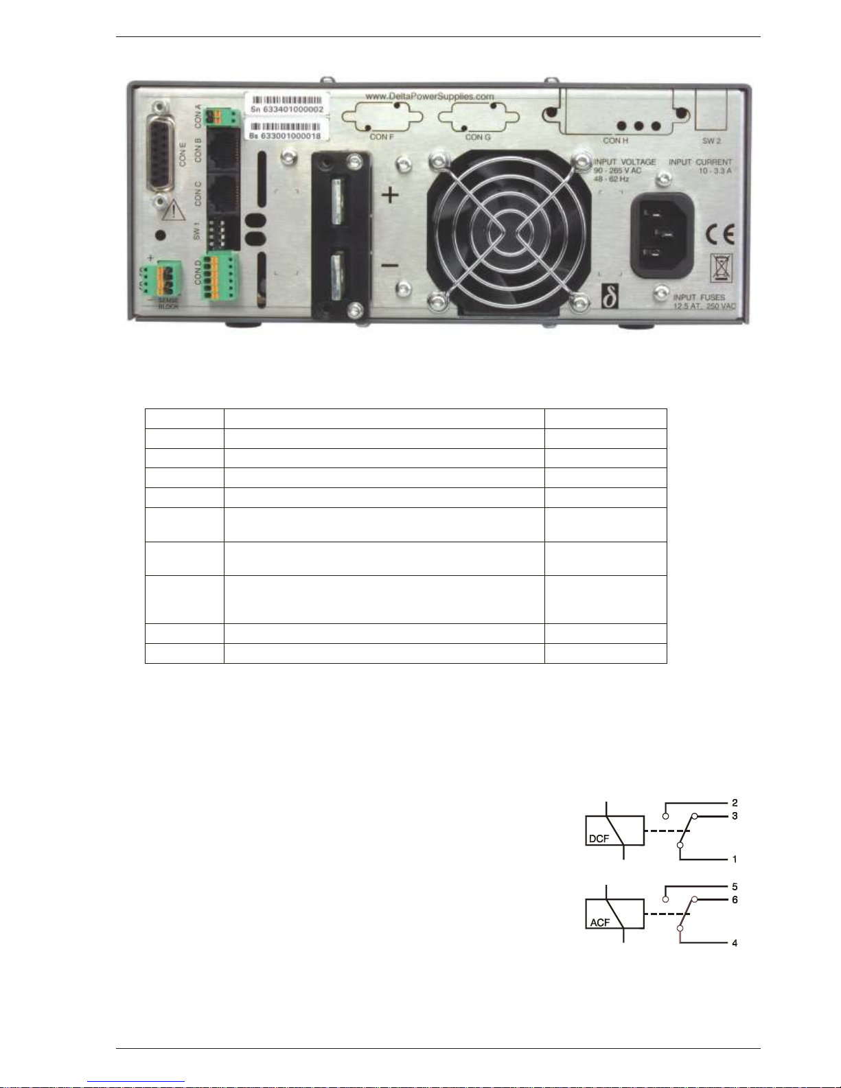
15) STATUS RE LAY OUT PUTS
The power sup ply has 2 sta tus re lay out puts, with each a change-over c on tact.
They are con nected to con nec tor CON D. The pins 1, 2, 3 are con nected to the
DCF-re lay and pins 4, 5, 6 to the ACF-re lay (see fig. 3 - 10). Pin 1 is the up per
out put, clos est to SW1.
fig. 3 - 8 Location of out put ter mi nals and an a log pro gram ming con nec tor on the rear panel (stan dard unit)
CON A In ter lock Con nec tor para graph 18)
CON B Mas ter Connector for Mas ter / Slave op er a tion (out put) para graph 31)
CON C Slave Connector for Mas ter / Slave op er a tion (in put) para graph 31)
CON D Re lay Out puts, con tacts 1 - 6 ACF / DCF para graph 15)
CON E An a log Pro gramming Connector para graph 9)
CON F PSC-ETH, user inputs
PSC-232, from PC or pre vi ous PSC (op tional)
para graph 11)
CON G PSC-ETH, user outputs
PSC-232, to next PSC (op tional)
para graph 11)
CON H PSC-ETH (op tional) or
PSC-488 (op tional) or
ISO AMP CARD (op tional)
para graph 10), 11)
SW 1 Var i ous set tings para graph 16)
SW 2 Set tings for PSC-488 and PSC-232 (op tional) -
fig. 3 - 9 Connectors and switches on the rear panel
fig. 3 - 10
Sta tus re lay out puts on CON D.
This sit u a tion gives the re lay
po si tions dur ing fault con di tion.
Page 7

DELTA ELEKTRONIKA BV SM800
Page 3 - 4 DESCRIPTIONS October 2007
16) FUNC TION SWITCHES ON SW1
In the above ta ble the func tions of the dipswitches 1-4 of switch
SW1 (rear side) are ex plained.
17) RE MOTE SHUT DOWN (RSD)
A volt age of +4 V...+12 V on the Re mote Shut Down in put on the
pro gram ming con nec tor CON E will switch off the out put of the unit.
It is also pos si ble to use a re lay con tact or a switch to shut the unit
down (see fig. 3 - 11).
In standby mode the power sup ply con sumes very lit tle power.
18) IN TER LOCK
The In ter lock con nec tor (CON A, rear panel) has 2 in puts which
have to be con nected to gether to turn on the out put of the unit.
As soon as the link be tween the 2 in puts of the In ter lock con nec tor
is dis rupted, the out put of the unit shuts down.
It can be used in com bi na tion with a cab i net door con tact (safet y
pre cau tion) or as an emer gency break to stop a mo tor which is
pow ered by the unit.
In case the link is dis rupted the RSD LED will light. In con trast with
Re mote Shut Down, also the DCF LED will be on, the DCF sta tus
will be high and the re lay con tact will change.
Once the in puts are con nected again, the out put will be on.
No volt age may be ap plied to the pi ns in the In ter lock connector.
19) PRO GRAMMING SPEED
The rise and fall time is mea sured with a step wave form at the CV
prog. in put. Pro gram ming from a low to a high out put volt age is
nearly load in de pend ent, but pro gram ming down to a low volt age
takes more time on lighter loads. This is caused by the out put ca pac i tors, which can only be dis charged by the load be cause the
power sup ply can not sink cur rent. With the Power Sink op tion,
also the pro gram ming down speed is nearly load in de pend ent.
When hav ing a unit with a Fast Pro gram ming op tion, the rise and
fall time is 5 to 25 times faster (see datasheet). The pro gram ming
source must be float ing or oth er wise an ISO AMP CARD must be
used, a non-float ing source will re sult in slope dis tor tion.
For a fast pro gram ming unit it is gen er ally not rec om mended to use
re mote sens ing or se rial / par al lel op er a tion. Con sult fac tory for ad vice. Note that the output rip ple is higher.
20) PUL SATING LOAD
To avoid over heat ing the out put ca pac i tors, the AC com po nent of
the load cur rent should be lim ited (see fig. 3 - 12).
One method of de creas ing the AC cur rent through the out put ca pac i tor is by us ing a large ex ter nal elec tro lytic ca pac i tor in par al lel
with the load. Care must be taken so that the ca pac i tor in com bi na tion with the lead in duc tance will not form a se ries res o nant cir cuit!
When us ing re mote sens ing on a pul sat ing load (for in stance a
DC-mo tor), use a ca pac i tor in se ries wit h a re sis tor over the load
(see fig. 3 - 13). Like this the AC-com po nent caused by the pul sat ing of the load is fil tered.
Note: in case of a pul sat ing load, the I mon i tor volt age will not ex -
actly match the out put cur rent. This is mainly caused by the cur rent
through the out put ca pac i tors. Re mote sens ing will worsen this ef fect.
21) IN SU LA TION
For safety the in su la tion of the sep a rat ing com po nents (trans form ers) be tween in put and out put is tested at 3750 Vrms dur ing
1 min ute. This is tested be fore as sem bly.
fig. 3 - 11
Re mote Shut Down us ing a re lay contact
fig. 3 - 12
Pul sating load current
fig. 3 - 13
Re mote sens ing on a pul sat ing load
fig. 3 - 14
In su la tion test voltages
Switch no. ON po si tion OFF po si tion De fault Set ting
SW 1 - 1 Pro gramming via 15pole con -
nec tor CON E (an a log).
Op tional pro gram ming with e.g.
PSC-232, PSC-488, ISO AMP CARD
ON (up)
SW 1 - 2 ‘Out put On’ af ter mains on ‘Out put Off’ af ter mains on OFF (down)
SW 1 - 3 DCF LED enabled DCF LED dis abled (DCF sta tus and
DCF re lay are still en abled)
ON (up)
SW 1 - 4 Par al lel Mas ter / Slave operation Se ries Mas ter / Slave operation ON (up)
Page 8

SM800 DELTA ELEKTRONIKA BV
October 2007 DESCRIPTIONS Page 3 - 5
Warn ing! The 3750 Vrms can not be tested af ter wards on the
as sem bled unit be cause the in su la tion be tween the com po nents on the in put side to the case (like the bridge rec ti fier) is
spec i fied at 2500 Vrms. Since the in su la tion out put - case is low
(only 600 VDC) the in su la tion of the pri mary com po nents to
case will break down when 3750 Vrms is ap plied be tween in put
and out put (2500 Vrms + 600 VDC < 3750 Vrms) (see also fig. 3
- 14).
Note: when test ing the in su la tion, take care to charge and dis charge the ca pac i tors be tween in put - cas e and out put - case
slowly (e.g. in one sec ond). This to prevent high peak cur rents,
which could de stroy the power sup ply. Make sure to dis charge
the ca pac i tors com pletely be fore us ing it again.
22) RFI SUP PRES SION
Both the in put and out put have RFI fil ters, re sult ing in very low
con ducted RFI to the line and load. Due to the out put fil ter the
out put volt age is very clean, hav ing al most no spikes.
23) OP ER ATING TEMPERATURE
At full power the op er at ing tem per a ture range is –20 to +50 °C.
From 50 to 60 °C the out put cur rent has to be de rated lin early to
75 % at 60 °C (see fig. 3 - 15). These tem per a tures hold for nor mal use, i.e. the ven ti la tion open ings on the left and right side
must be free.
24) THER MAL PRO TEC TION
A ther mal switch shuts down the out put in case of in suf fi cient
cool ing.The OT sta tus will be high. Af ter cool ing down the unit
will start work ing again.
The OT-LED on the front panel will be on and the OT-status sig nal will be "1" in case of a trip ped ther mal pro tec tion.
As a pre-warning the OT-LED blinks (sta tus will still be low), this
will start be fore the power sup ply shuts down.
25) HOLD - UP TIME
The hold - up time de pends on the load and the out put volt age.
A lighter load or a lower out put volt age re sults in a lon ger hold up time (see fig. 3 - 16).
26) TURN ON DE LAY
The out put volt age is avail able about 0.5 s af ter mains switch on.
27) IN RUSH CUR RENT
The in rush cur rent is lim ited with a spe cial cir cuit.
Re peat edly switch ing on and off does not change the max i mum
peak cur rent.
Switching on and off at a fast rate can over heat the in rush cur rent lim iter. With the re sult that the unit does not start any more.
Af ter cool ing down (mains switched off) it will be OK again.
28) RE MOTE SENSING
The volt age at the load can be kept con stant by re mote sens ing.
This fea ture is not rec om mended for nor mal use but only when
the load volt age is not al lowed to vary a few mil li volts. Al ways
use a shielded ca ble for sens ing.
In or der to com pen sate for the volt age drop acros s the load
leads, the unit will have to sup ply a higher volt age, see fig. 3 - 17:
Uout = (volt age drop across each lead) + (volt age across the load).
The volt age limit reads the volt age di rectly at the out put ter mi nals. The set ting for the limit must there fore be in creased by the
to tal volt age drop across the load leads.
The volt age dis play on the frontpanel and the volt age mon i tor
out put on CON E are con nected to the sense leads and there fore read the volt age across the load and not the volt age on the
out put ter mi nals.
The sense leads are pro tected against ac ci den tal in ter rup -
tion. The max i mum volt age be tween the out put ter mi nals and
the sense in puts is lim ited at 2.5 V.
For sens ing on a pul sat ing load see pre vi ous para graph 20).
fig. 3 - 15
Op er ating tem per a ture ranges
fig. 3 - 16
Hold-up time vs Vout with Iout as a parameter
fig. 3 - 17
Re mote sens ing, volt age drop in load leads sub -
fig. 3 - 18
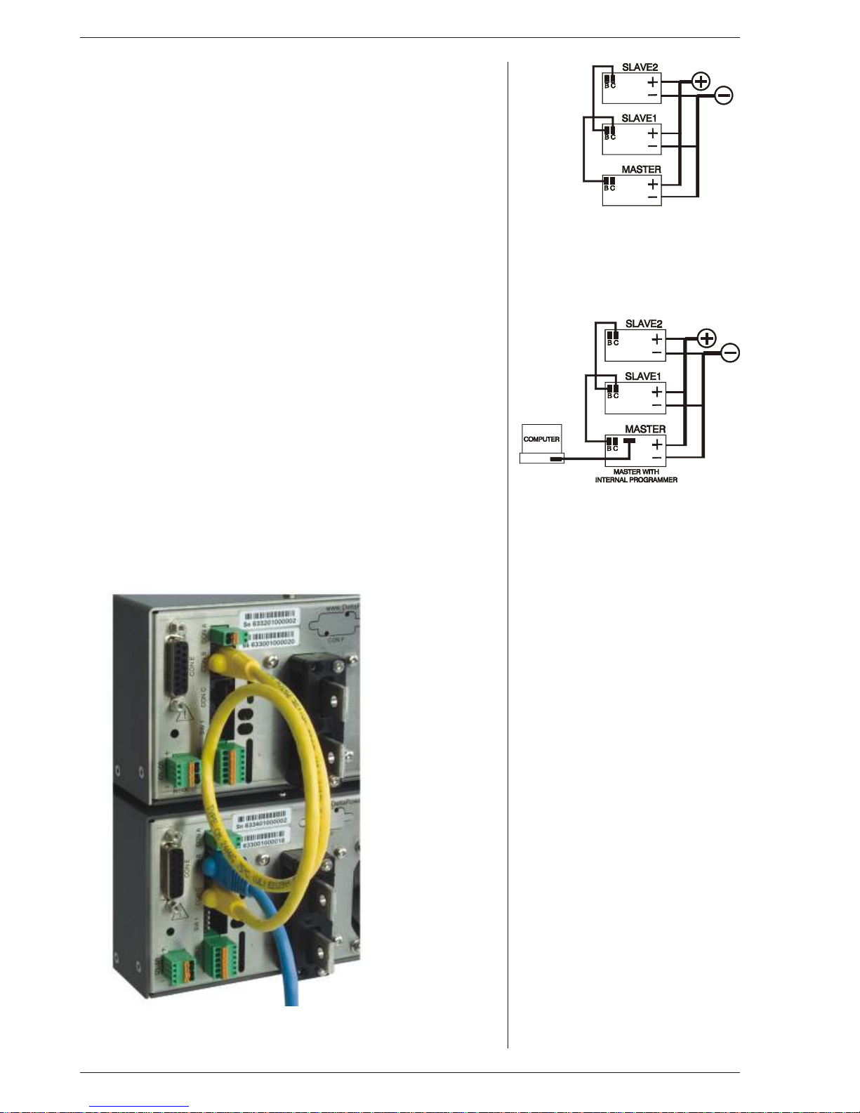
Mas ter / Slave se ries op er a tion
Page 9
DELTA ELEKTRONIKA BV SM800
Page 3 - 6 DESCRIPTIONS October 2007
29) SERIES OP ER A TION
Se ries op er a tion is al lowed up to 600V to tal volt age. The power sup plies can
be con nected in se ries wit h out spe cial pre cau tions.
For eas ier con trol, Mas ter / Slave op er a tion is rec om mended (see fig. 3 - 18).
By us ing the Mas ter / Slave Se ries fea ture a dual track ing power sup ply can
be made with one unit as mas ter and one as slave.
For se ries op er a tion in com bi na tion with Power Sink op tion, all units must
have a Power Sink built in side oth er wise no power can be ab sorbed. Re fer to
Power Sink man ual for de tails and re stric tions.
30) PAR AL LEL OP ER A TION
Par al leling of t he units has no lim i ta tions. The power sup plies can be con nected in par al lel with out spe cial pre cau tions. For eas ier con trol, Mas ter /
Slave op er a tion is rec om mended (see fig. 3 - 19).
Nor mal par al lel op er a tion of Fast Pro gram ming units can give prob lems,
each com bi na tion has to be tested first, in com bi na tion with the load !
For par al lel op er a tion in com bi na tion with Power Sink op tion, only one unit
can have a Power Sink. Re fer to Power Sink man ual for de tails and re stric tions.
31) MASTER / SLAVE OP ER A TION
The Mas ter / Slave fea ture makes it pos si ble to use the power sup plies as
build ing blocks to form one large unit (see fig. 3 - 18 and fig. 3 - 19).
Mixed par al lel - se ries op er a tion is also pos si ble, to a max i mum of 600V.
The re sult ing com bi na tion of units be haves like one power sup ply and can be
man u ally con trolled or pro grammed on the mas ter. Fig. 3 - 20 shows a com puter con trolled M / S par al lel com bi na tion.
Con nect the dif fer ent units with stan dard RJ45 ca bles (see fig. 3 - 21), us ing
CON B and CON C on the rear side. With dipswitch 4 of switch SW1 the Par al lel or Se ries mode can be se lected.
The slaves will fol low the mas ter. The re sult is true cur rent or volt age shar -
ing in the par al lel or se ries mode re spec tively.
Note: Mas ter / Slave par al lel op er a tion is not rec om mended for more
than 4 units or in com bi na tion with Fast Pro gram ming op tion.
Con sult fac tory for a so lu tion.
fig. 3 - 19
Mas ter / Slave parallel operation
fig. 3 - 20
The Mas ter / Slave com bi na tion can also
be pro grammed with the in ter faces
PSC-ETH, PSC-488 or the PSC-232
fig. 3 - 21
Use stan dard UTP ca bles (RJ45)
for Mas ter / Slave operation
Page 10

SM800 DELTA ELEKTRONIKA BV
October 2007 DESCRIPTIONS Page 3 - 7
32) VOLT AGE AND CUR RENT LIMIT
The Volt age and Cur rent Lim its main tain the out put to a safe pre set value.
They do not trip, so no re set ting is needed af ter a fault. It can be very handy to
have hard ware lim its when the power sup ply is pro grammed.
The lim its can eas ily be set by press ing the DIS PLAY LIM ITS but ton and
ad just ing the limit po ten ti om eters wi th a screw driver. The LED’s next to the
limit potmeters in di cate the ac tiv ity of each limit, also the LIM-sta tus out put will
be "1".
The Volt age Limit will pro tect your cir cuit from un wanted high volt ages. A high
out put volt age could be caused by ac ci den tal in ter rup tion of leads, ac ci den tally
turn ing up the volt age potmeter, a pro gram ming er ror or a de fect in the power
sup ply. The Volt age Limit cir cuit uses a sep a rate volt age di vider con nected di rectly to the out put ter mi nals.
The Cur rent Limit pro tects your cir cuit from un wanted high cur rents.
Note: In the Autoranging units the limit cir cuits are also used as "range lim its".
This can be con fus ing. Ex am ple: an SM70-AR-24 op er at ing in the range above
35 V will au to mat i cally re duce the limit set ting to a max i mum of 12 A.
Warn ing: if this unit op er ates in the range be low 35V, this set ting is 24 A !
Take care the out put ca bling and the load can with stand such a high cur rent or
oth er wise re duce the limit set ting to a lower value.
33) PO TEN TI OM E TERS
° Stan dard: - CV and CC po ten ti om eters with knobs at front panel,
Volt age Limit and Cur rent Limit po ten ti om eters with
screw driver ad just ment at the front panel.
° Op tion P001: - Screw driver ad just ment for CV, CC, Volt age Limit and
Cur rent Limit at the front panel (fig. 3 - 22).
34) COOLING
A low noise blower cools the unit. The speed of the fan de pends on the tem per a ture of the in ter nal heatsink. Normally at 50 °C am bi ent and full load the fan
will not work at full speed.
A spe cial fea ture is that the fan blows through a tun nel where the heatsink is
sit u ated, the del i cate con trol cir cuitry is sep a rated and will not be in the air flow
path (see fig. 3 - 23).
Be cause the air en ters at the rear side and ex its at the left and right side, it is
pos si ble to stack the power sup plies, no dis tance be tween the units is re quired.
Be cause only one of the ven ti la tion open ings at the left side or right side should
be free, it is pos si ble to put two units in par al lel in a rack.
For long life the tem per a ture of the air en ter ing on the left side, should be
be low 35 °C un der nor mal con di tions. Un der ex treme conditions it should be
be low 50 °C.
Note: The con trol cir cuit makes the fan start in a pul sat ing mode, dur ing which
pe riod it can pro duce a high pitc hed sound. This is nor mal.
35) DI MEN SIONS
fig. 3 - 22
Screw driver ad just ment at front panel.
Be hind the plas tic caps, the CV- and
CC-set tings can be ad justed
with a screw driver.
fig. 3 - 23
The fan blows through an in ter nal tun nel,
where the heatsink is sit u ated.
Al ways take care to have at least one air
out let un ob structed.
Page 11

DELTA ELEKTRONIKA BV SM800
Page 4 - 1 OPERATING MAINTENANCE TROUBLE SHOOTING CALIBRATING October 2007
OPERATING MANUAL
1) OP ER ATING THE UNIT FOR THE FIRST TIME
• Check there is no con den sa tion on the unit. If there is, al low some
time to dry.
• Check there is a link be tween + and S+ and be tween – and S– on
the SENSE BLOCK (on rear panel).
• Check there is a link be tween the in puts of the In ter lock (CON A,
rear panel).
• Set the CV and CC po ten ti om eters to min i mum (fully anti clock -
wise).
• For rec om mended ca ble di am e ters and torque (see table 4 - 1)
• With high out put cur rent make sure to use low re sis tive con -
nec tions be tween the power sup ply and the load:
- Mount the ca ble lugs di rectly on the tinned out put strips
fol lowed by a washer, a split washer and a nut (see fig. 4 - 1).
Al ways in this or der!
- Never place wash ers be tween the lugs and the strips
be cause this can re sult in ex ces sive heat!
- Only use nuts and wash ers sup plied with the unit.
• Switch on unit.
• Dis able the Key lock func tion, see next para graph 2).
• Check the unit is not in Re mote CV or Re mote CC (LED’s for this
func tion should be off). Press the RE MOTE/LO CAL but ton un til
both LED’s are off.
• Turn on the out put by press ing the OUT PUT ON/OFF but ton.
• Turn both the CV and CC po ten ti om e ter a few turns clock wise.
A volt age should now be pres ent on the out put.
• By press ing the DIS PLAY CV/ CC SETT ING but ton, the me ters
will show the set ting of the CV and CC po ten ti om e ter.
• By press ing the DIS PLAY LIMITS but ton, the volt me ter will show
the set ting of the CV-limit and the CC-limit potentiometer.
• Check the cool ing of the unit is not ob structed.
2) KEY LOCK
• If the func tion KEY LOCK is ac ti vated, it is no lon ger pos si ble to
op er ate the RE MOTE/LO CAL but ton and the OUT PUT ON/OFF
but ton. This func tion can be use ful to pro tect the out put from ac ci den tal shut down. The func tion KEY LOCK does not in flu ence the
operating of the potentiometers.
• Ac ti vate Key lock:
Pressing the but tons DIS PLAY SET TINGS and DIS PLAY
LIMITS at the same time for more than 3 sec onds, ac ti vates the
func tion KEY LOCK. The mo ment this func tion is ac ti vated, the
LED’s for RE MOTE CV / CC and for OUT PUT ON will blink a few
times.
• Dis able Key lock:
Pressing the same but tons again for 3 sec onds, dis ables the
Key lock function. The LED’s for RE MOTE CV / CC and for OUT PUT ON will blink again to in di cate the new set ting.
3) AN A LOG PRO GRAM MING
• Set dipswitch 1 of SW1 in po si tion ON to se lect CON E for pro -
gram ming.
• Dis able Key lock.
• Set the unit in RE MOTE CV for volt age pro gram ming and/or in
RE MOTE CC for cur rent pro gram ming.
Use the RE MOTE/LO CAL but ton and push this but ton sev eral
times un til the right set ting is ac ti vated.
Note that pushing the RE MOTE/LO CAL but ton will shut down the
out put to avoid ac ci den tal dam age to the load.
• Con nect the pro gram ming volt age source(s) (0 - 5 V) to the an a -
log pro gram ming con nec tor CON E on the rear panel (see fig.
4 - 2 and fig. 4 - 3). Al ways use a shielded ca ble (max. 30 me ter)
for pro gram ming.
• Turn the out put on again with the OUT PUT ON/OFF but ton.
• If only the volt age is pro grammed, the max i mum cur rent can still
be set with the CC po ten ti om e ter and vice versa. If this is not de sir able the unit can be or dered with Op tion P001 in or der to have
a fixed set ting for the CV or the CC po ten ti om e ter on the front
panel.
fig. 4 - 1
Low re sis tive ca ble con nec tion by mount ing the
ca bles di rectly on the tinned out put strips
fig. 4 - 2
Pro gram ming by volt age:
left volt age -, right cur rent pro gram ming
fig. 4 - 3
Pro gram ming by cur rent
left volt age -, right cur rent pro gram ming
Unit Out put ca bles
[mm2]
Bolts Torque
[Nm]
SM7.5-80 16 M5 5
SM18-50 10 M5 5
SM70-AR-24 4 M5 5
SM400-AR-4 1 M5 5
ta ble 4 - 1
Rec om mended ca ble di am e ters and
mount ing torque
Page 12

SM800 DELTA ELEKTRONIKA BV
October 2007 OPERATING MAINTENANCE TROUBLE SHOOTING CALIBRATING Page 4 - 2
• To avoid hum or noise, t he pro gram ming ca ble may have to
be twisted in some cases.
• To pro gram the unit by cur rent in stead of volt age, sim ply use a
par al lel re sis tor as a cur rent to volt age con verter.
• Pressing the DIS PLAY SET TINGS but ton will show the pro -
grammed val ues for CV and CC.
• CAU TION: The an a log in puts are not iso lated from the out put.
The Ø of the prog. in put (pin 1) is in ter nally con nected to the
S–, the S– is con nected to the neg a tive out put. To pro tect the
in ter nal wir ing a 650 mA self-resetting fuse is con nected in se ries (F27_1 on P647). To avoid earth loops, use an iso lated
pro gram ming source. If this is not pos si ble see next par a graph 4), for us ing the op tional ISO AMP CARD.
4) AN A LOG PRO GRAMMING WITH ISO AMP CARD
• For pro gram ming via the ISO AMP CARD, set dipswitch 1 on
SW1 in the po si tion OF F.
• When the ISO AMP CARD is built in side the unit, CON E has
been covered. Use CON H in stead. The pin ning of CON H is
equal to the pin ning of CON E.
• For fur ther op er at ing in struc tions, see pre vi ous para graph 3).
5) Ethernet / IEEE 488 / RS232 PRO GRAMMING
• Set dipswitch 1 on SW1 in po si tion OFF for pro gram ming with
the PSC-ETH, the PSC-488 or the PSC-232.
With dipswitch 1 in this po si tion, the sig nals Vprog (pin 11) and
Iprog (pin 3) are dis abled on CON E. All the other sig nals can
still be used. For Ethernet pro gram ming CON H must be used,
CON F and G can be used for the user in- and out puts.
For IEEE488 also CON H must be used for pro gram ming.
For RS232 pro gram ming CON F and G must be used.
• Set the unit in RE MOTE CV for volt age pro gram ming and/or in
RE MOTE CC for cur rent pro gram ming us ing the SCPI com mands (see man ual PSC) or us ing the RE MOTE/LO CAL but ton on the unit. Push this but ton sev eral times un til the r ight
set ting is ac ti vated. Set ting the unit in RE MOTE or LO CAL will
cause the out put to shut down to avoid ac ci den tal dam age to
the load. Turn it on again us ing the SCPI com mand or with the
OUT PUT ON/OFF but ton.
• Set dipswitch 1 on SW1 in po si tion ON to enable CON E again
for an a log pro gram ming.
In this po si tion volt age and cur rent pro gram ming on CON F
and H is dis abled. The other func tions and sig nals can still be
pro grammed and read back.
6) MON I TORING OUT PUTS
• The 5 V level is com pat i ble with most in ter faces.
• The mon i tor ing out puts can drive a me ter di rectly, fig. 4 - 4.
7) STATUS OUT PUTS
• The sta tus out puts have a sep a rate Ø con nec tion (pin 8) to
avoid un wanted off sets in the pro gram ming. This pin is pro tected with a 650 mA self re set ting fuse (F27_2 on P647).
8) RE MOTE SENSING
• Re move the links on the SENSE BLOCK (on rear panel) and
con nect sense leads (thin shielded mea sur ing wires) to S+
and S– (see fig. 4 - 5 and fig. 4 - 6).
• With re mote sens ing the volt age on the load can be kept con -
stant. The volt age drop in the load leads will be com pen sated.
This fea ture is not rec om mended for nor mal use, be cause it
can eas ily give prob lems.
• Max. 2 V per load lead can be com pen sated. Note that the
volt age drop in the leads de creases the max. out put volt age
rat ing. In fig. 4 - 7 it can be seen that on a 15V power sup ply
only 11V will be avail able on the load when 2x 2V com pen sa tion is used.
• In or der to pre vent in ter fer ence, it is ad vis able to twist the
sense leads. To mini mise the in duc tance in the load leads
keep the leads close to each other. The in duc tance of the
loads leads could give a prob lem with pul sat ing loads. In this
fig. 4 - 4
Re mote con trol
fig. 4 - 5
Lo cal sens ing
fig. 4 - 6
Re mote sens ing with shielded wires
fig. 4 - 7
Re mote sens ing, volt age drop in load leads
subtracts from max. out put
Page 13

DELTA ELEKTRONIKA BV SM800
Page 4 - 3 OPERATING MAINTENANCE TROUBLE SHOOTING CALIBRATING October 2007
case a large elec tro lytic ca pac i tor (Cd) in se ries with a
damp ing re sis tor (Rd) both in par al lel with the load will help
(see fig. 4 - 6). Check that the ca pac i tor Cd in com bi na tion
with the load leads and re sis tor Rd forms a well damped cir cuit.
• Since the volt me ter is in ter nally con nected to the sens ing
ter mi nals, it will au to mat i cally in di cate the volt age on the
load. Note that the volt age mea sured on the load will be
lower than on the out put ter mi nals.
• The Over Volt age Limit mea sures the volt age on the out put
ter mi nals, so the OVL set ting should be in creased by the
to tal volt age drop in the load leads.
9) BAT TERY CHARGER
• The CV / CC reg u lated power sup plies are ideal bat tery
charg ers. Once the out put is set at the cor rect volt age the
bat tery will charge con stantly with out over charg ing.
This can be use ful for emer gency power sys tems.
• Pro tec tive mea sures
Use a CIR CUIT-BREAKER in se ries in or der to pro tect the
power sup ply from ac ci den tal re verse con nec tion (see
fig. 4 - 8). The cir cuit-breaker should have a DC volt age rat ing twice the bat tery volt age. Use the very fast type (Z), a
type meant for pro tect ing semi con duc tors (see ta ble 4 - 2).
The unit has a re verse di ode in par al lel with the out put, this
di ode and the wir ing can not with stand the thou sands of
am peres sup plied by a wrongly c on nected bat tery.
10) RE MOTE SHUTDOWN
• The Re mote Shut down can be op er ated on CON E by a
volt age of +4V...+12V or by a re lay con tact be tween Vref
and Re mote Shut Down (pin 9 and 5) (see fig. 4 - 9).
• When the unit is pro grammed with an op tional PSC, a
soft ware com mand can be used for Re mote Shut down.
• In the Re mote Shut down con di tion, the RSD LED will light.
The DCF LED, DCF sta tus and the DCF re lay will be off.
Im por tant: If the link from the In ter lock con nec tor (CON A)
has been re moved, the RSD LED will be on, but in this
con di tion also the DCF LED, the DCF sta tus and the DCF
re lay will be on.
11) MASTER / SLAVE SERIES OP ER A TION
• Con nect out put ter mi nals and test sys tem in nor mal
se ries op er a tion. En sure that all (out put) power con nec -
tions are re li able.
• The volt age drop in the con nect ing leads be tween the units
should be kept < 10 mV.
• Switch of f all units. Con nect units as shown in fig. 4 - 10.
To con nect the slaves with the mas ter via CON B and CON
C, use stan dard UTP ca bles (RJ45).
On all units put dipswitch 4 of SW1 in po si tion OF F to s et
the units in M/S se ries mode.
• Af ter turn ing the units on again, the slaves will be in Re mote
CV mode and the Keylock, see pre vi ous para graph 2) is ac ti vated. This is be cause the unit au to mat i cally de tects the
pres ence of the RJ45 con nec tor in CON C (if this ca ble is
con nected to an other unit).
If the RJ45 con nec tor is re moved from CON C when the
unit is turned on, the out put will shut down to avoid
ac ci den tal dam age.
If the ca ble is in serted when the unit is turned on, the out put
shuts down, the unit changes to Re mote CV / CC, the
Keylock will be ac ti vated and the out put will turn back on.
If dipswitch 4 of SW1 is op er ated when the unit is turned on,
the out put will shut down to avoid ac ci den tal dam age.
• The max. num ber of slaves is only lim ited by the max. to tal
volt age of 600 V.
Sug gested Cir cuit Breakers for pro tec tion power sup ply
Model Type num ber
Cir cuit Breaker
Brand Re marks
SM7.5-80 S281 UC-B 100 ABB SM18-50 S281 UC-Z 63 ABB SM70-AR-24 S281 UC-Z 25 ABB SM400-AR-4 S281 UC-Z 6 ABB ex tra par al lel di ode
on out put needed.
2x BYT261in series
ta ble 4 - 2
Cir cuit break ers for pro tec tion.
fig. 4 - 8
Charg ing bat tery with a cir cuit-breaker in se ries
fig. 4 - 9
Re mote shut down with switch
fig. 4 - 10
Mas ter / Slave se ries con nec tion
Page 14

SM800 DELTA ELEKTRONIKA BV
October 2007 OPERATING MAINTENANCE TROUBLE SHOOTING CALIBRATING Page 4 - 4
12) MASTER / SLAVE PAR AL LEL OP ER A TION
• Note: Mas ter / Slave par al lel i s not rec om mended
for more than 4 units, con sult fac tory for us ing
more than 4 power sup plies in par al lel.
• First, con nect out put ter mi nals and test sys tem in
nor mal par al lel op er a tion. En sure that all power
con nec tions are re li able.
• Sec ond, switch off all units. To con nect the slaves with
the mas ter via CON B and CON C, use stan dard RJ45
con nec tors ac cord ing to fig. 4 - 11.
On all units put dipswitch 4 of SW1 in po si tion ON to set
the units in M/S par al lel mode. In this mode the DCF
LED, DCF re lay and DCF sta tus on the slaves are
dis abled be cause the slaves are al ways in CC mode.
• Af ter turn ing the units on again, the slaves will be in
Re mote CC mode and the Keylock, see pre vi ous para graph 2) is ac ti vated. This is be cause the unit au to mat i cally
de tects the pres ence of the RJ45 con nec tor in CON C
(if this ca ble is con nected to an other unit).
If the RJ45 con nec tor is re moved from CON C when
the unit is turned on, the out put will shut down to avoid
ac ci den tal dam age.
If the ca ble is in serted when the unit is t urned on, the
out put shuts down, the unit changes to Re mote CV /
CC, the Keylock will be ac ti vated and the out put will
turn back on.
If dipswitch 4 of SW1 is op er ated when the unit is
turned on, the out put will shut down to avoid ac ci den tal
dam age.
• Stack the units to cre ate a min i mum dis tance be tween
the units. Keep the load close to the mas ter.
Use cop per str ips (pre ferred) or short thick ca bles to
con nect the units. Make sure the strips are mounted
with a min i mum lengt h to keep the volt age drop be tween a unit and the bus bar be low 10 mV. Also keep
the strips close to each other to have a low in duc tance.
Not fol low ing these in struc tions can cause in sta bil ity.
• The S- and S+ could be con nected to the load if
de sired, but this is not rec om mended be cause of the
com plex ity and pos si ble instability.
13) PAR AL LEL OP ER A TION OF FAST
PRO GRAMMING VER SIONS:
• Mas ter / Slave op er a tion is not rec om mended.
• Nor mal par al lel op er a tion can give prob lems, each
com bi na tion has to be tested first in com bi na tion with
the load.
14) MASTER / SLAVE MIXED SERIES /
PAR AL LEL OP ER A TION
• For com plex com bi na tions as mixed se ries - par al lel,
al ways use a MAS TER / SLAVE SE RIES ADAPTER.
• See fig. 4 - 12 for an ex am ple of how to con nect 2 units
in se ries in par al lel with 2 units in se ries, con trolled by 1
mas ter.
• Set the pro gram ming mode with the knob Re mote / Lo -
cal on the front panel. The se rial slaves must be in Re mote CV mode. The par al lel slave must be in Re mote
CC mode.
• Note: A Mas ter / Slave com bi na tion can al ways be
pro grammed, also with the IEEE488 / RS232 con trol ler
(PSC-448 / PSC-232 (both δ-prod ucts)).
fig. 4 - 11
Mas ter / Slave par al lel connections
fig. 4 - 12
Mas ter / Slave mixed se ries - par al lel connections
Page 15

DELTA ELEKTRONIKA BV SM800
Page 4 - 5 OPERATING MAINTENANCE TROUBLE SHOOTING CALIBRATING October 2007
OPERATING AND STORAGE CONDITIONS
1) TEM PER A TURE
• The op er at ing tem per a ture range at full load is –20 to +50 °C.
But this tem per a ture range only holds when the AIR-IN TAKE and
at least one of the AIR-OUT LETS is un ob structed and the tem per a ture of the AIR-IN TAKE is not higher than +50 °C.
• Please note: a lower tem per a ture ex tends the life of the
power sup ply.
• When the power sup ply is mounted in a cab i net please note that
the tem per a ture of the AIR-INTAKE should be kept low and avoid
a short cir cuit in the air flow i.e. the hot air leav ing the AIR-OUTLET
en ter ing the AIR-INTAKE again.
• The stor age tem per a ture range is –40 to +85 °C.
2) HU MID ITY
• Dur ing nor mal op er a tion hu mid ity will not harm the power sup ply,
pro vided the air is not ag gres sive. The heat nor mally pro duced in
the power sup ply will keep it dry.
• Con den sa tion.
Avoid con den sa tion in side the power sup ply, break-down could
be the re sult.
Con den sa tion can oc cur dur ing a pe riod the power sup ply is
switched off (or op er at ing at no load) and the am bi ent tem per a ture
is in creas ing .
Al ways al low the power sup ply to dry be fore switch ing it on again.
3) GAL VANIC IN DUS TRY
• For us ing the power sup plies in the gal vanic in dus try it is strongly
rec om mended to take pre cau tions against an ag gres sive en vi ron ment.
• An ag gres sive en vi ron ment with acid, salt, etc. can harm the elec -
tronic com po nents. Some times even the cop per tracks on the
printed cir cuit boards dis solve.
• To avoid prob lems, the power sup plies should be mounted in a
rel a tively clean room, or mounted in a cab i net re ceiv ing clean air
with over pres sure, or in a cab i net with a heat exchanger.
MAINTENANCE
1) GEN ERAL
• The SM-series power sup plies nor mally need no main te nance or
cal i bra tion. Only care must be taken that the cool ing of the unit is
not ob structed.
2) COOLING FAN
• The built up of dust on the im pel ler of the fan and the heat sink fins
de pends on the en vi ron ment. Since the fan has over-ca pac ity,
dust will not pres ent a prob lem very quickly.
• The in ter nal con struc tion of the power sup ply is such that no dust
will reach the sen si tive con trol cir cuitry, only the heat sink in a tun nel will be cooled by forced air (see fig. 4 - 13).
• The ther mal pro tec tion will shut down the out put in case of over -
heat ing, so the power sup ply will not be dam aged.
• It is ad vis able to in spect the fan and the heat sink reg u larly.
fig. 4 - 13
The fan blows through an in ter nal tun nel,
where the heatsink is sit u ated.
Al ways take care to have at least one air out let
un ob structed.
Page 16
SM800 DELTA ELEKTRONIKA BV
October 2007 OPERATING MAINTENANCE TROUBLE SHOOTING CALIBRATING Page 4 - 6
TROUBLE SHOOTING
1) GEN ERAL
• In case you need as sis tance f or re pair ing a unit, please con tact
our en gi neers us ing the ad dress "Sup port@Delta-Elektronika.nl".
• In case you want us t o re pair the unit, please first fill out the
RMA-form be fore send ing the unit to us. Add ing a de tailed fault
de scrip tion will help us to re pair the unit as soon as pos si ble.
On our website www.DeltaPowerSupplies.com the RMA-form
can be found un der 'Sup port'.
2) NO OUT PUT (man ual con trol)
• Check the LEDs ‘Re mote CV’ and ‘Re mote CC’ on the front panel,
they should be off. Dis able Key lock and press the RE MOTE/LO CAL button to turn both LEDs off.
• The LED ‘Out put On’ should be on. If this LED is off, dis able Key -
lock and push the but ton ‘OUT PUT ON/OFF’.
• Check the con nec tions on the SENSE BLOCK (at rear panel),
there should be a link be tween + and S+ and be tween – and S–
(see fig. 4 - 16).
• Check if there is a link in the In ter lock con nec tor (if not, the RSD
LED will be on).
• Set both the CV- and C C-limit po ten ti om e ter (at front panel) at
max i mum (fully clock wise).
• Turn both the CV and CC po ten ti om eters a few turns clock-wise.
A volt age should be pres ent on the out put.
• Dis con nect the ca bles from the out put and check if now there's a
volt age pres ent on the out put. If this is the sit u a tion, use a load
with a higher im ped ance or use a sec ond power sup ply in parallel.
3) PRO GRAMMING DOES NOT WORK OK
• Check the unit is in Re mote mode (Re mote CV and/or Re mote CC
LED should be on).
• The unit works OK in man ual con trol, but in pro gram ming
mode the out put volt age / cur rent has a large er ror.
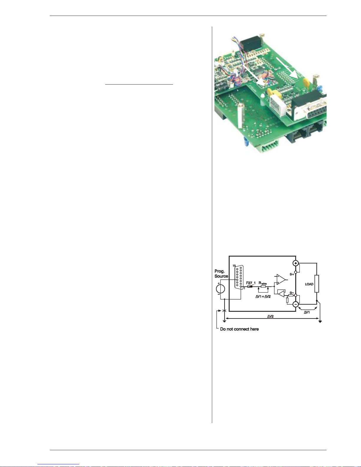
Prob a bly the fuse in se ries with Ø (pin 1) of pro gram ming
connector trip ped, the fuse (F27_1 = 650 mA) is a self-resetting
type (see fig. 4 - 14).
• To check the fus e (F27_1) mea sure the v olt age be tween Ø and
the mi nus out put, dur ing the fault con di tion. The volt age should
only be a few mV, a high volt age means that an un wanted cur rent
is flow ing through pin 1 of the prog. con nec tor.
Please check why cur rent is flow ing through pin 1 (see next para graph 4) and fig. 4 - 15).
4) PRO GRAMMING OFF SETS
• Un wanted off sets in the pro gram ming can be caused by
earth loops.
Fig. 4 - 15 shows a typ i cal earthing prob lem. In case the load has a
con nec tion to earth and the pro gram ming source as well, prob lems could oc cur. Im proper choice of the earthing point of the load
can give a volt age drop of ∆V1. Con necting the mi nus or zero to a
sep a rate earth con nec tion can give a volt age drop of ∆V2. Be -
cause the in ter nal wires of the pro gram ming in put are t hin, the
volt age drops ∆V1 and ∆V2 will be across the in ter nal wir ing as
well. Re sulting in an er ror volt age in se ries with the pro gram ming
volt age.
• The best so lu tion for this is to use a float ing pro gram ming source,
a float ing load or the op tional in ter nal ISO AMP CARD (δ-prod uct).
5) STATUS OUTPUTS FAIL
• Check fuse F27_2 in se ries with Ø (pin 8 of CON E) (see fig. 4 -
14). To check the fuse mea sure the volt age be tween Ø and the mi nus out put, a high volt age means too much cur rent flow ing
through the fuse. F27_2 = 650 mA, self resetting.
fig. 4 - 14
Lo ca tion of pro gram ming fuses on P647
P647 is sit u ated di rectly be hind the rear panel
fig. 4 - 15
Un wanted pro gram ming off sets
Page 17

DELTA ELEKTRONIKA BV SM800
Page 4 - 7 OPERATING MAINTENANCE TROUBLE SHOOTING CALIBRATING October 2007
6) MASTER / SLAVE PAR AL LEL PROB LEMS
• Check the volt age drop of the wir ing be tween the mas ter and the
slaves is < 10 mV.
• Check the wir ing has a low in duc tance.
7) OUT PUT VOLT AGE IS HIGHER THAN SET VALUE
• Check con nec tions on SENSE BLOCK (on rear panel), For nor -
mal op er a tion there should be a link be tween + and S+ and be tween – and S– (see also fig. 4 - 16). When re mote sens ing is
used, check the wires of the sens ing.
8) OT LED on
• The tem per a ture of the in ter nal heat sink is too high,
the out put has been shut down to avoid overheating.
• Check if the cool ing fan is run ning.
• Check if the air tem per a ture of the air in let (left) is be low 50 °C and
the air flow is not ob structed.
9) OT LED blinks
• The tem per a ture of the in ter nal heat sink is get ting too high, a fur -
ther in crease will shut down the power sup ply.
• Check if the cool ing fan is run ning prop erly.
• Check if the air t em per a ture of the air in lets (left) is be low 50 °C
and the air flow is not ob structed.
10) ACF LED on
• The in put volt age is too low or was in ter mit tent be cause of a bad
con nec tion. Dis con nect the mains, wait a few min utes and try
again.
As soon as the ACF LED Iights, the set tings for Re mote CV,
Remote CC and Key lock will be saved. If the unit turns back on, it
will have the same set tings. For the set ting of Out put On/Off af ter
turn ing the unit back on, the po si tion of dipswitch 2 on SW1 is de ter min ing.
If the ACF sit u a tion lasts a few sec onds, the out put will shut down.
The ACF prob lem has to be solved first, be fore the out put can be
turned on again.
• In ter nal er ror, send unit for re pair. See pre vi ous para graph 1) .
11) DCF LED on
• The out put volt age is below the set volt age. This au to mat i cally
hap pens when the unit is in CC-mode (CC LED is on).
Also with an interrupted In ter lock con nec tor, the DCF LED will be
on.
• In ter nal er ror, send unit for re pair. See pre vi ous para graph 1).
12) PSOL LED on
• The Power Sink is in over load or the tem per a ture of the Power
Sink is too high. See datasheet of the Power Sink op tion for fur ther
de tails.
13) NO LEDS on
• Check in put.
• Do not try to re pair, but send for re pair. See pre vi ous para graph 1).
14) Blink ing LEDs RE MOTE CV, RE MOTE CC and
OUT PUT ON
• This in di cates the Keylock func tion is ac ti vated, see pre vi ous
para graph 2) in "op er at ing man ual".
15) OTHER
• If the prob lem per sists, please fill out the RMA-form on our website
www.DeltaPowerSupplies.com. See pre vi ous para graph 1) .
fig. 4 - 16
For nor mal op er a tion links should be con nected
be tween S+ and + and be tween S– and –
Page 18

SM800 DELTA ELEKTRONIKA BV
October 2007 OPERATING MAINTENANCE TROUBLE SHOOTING CALIBRATING Page 4 - 8
CALIBRATION
1) GEN ERAL
• The power sup plies are fac tory cal i brated
and nor mally need no fur ther cal i bra tion.
Only in spe cial sit u a tions (for ex am ple af ter
repairing a unit) cal i bra tion can be nec es sary.
2) METER CAL I BRA TION
• DIG I TAL ME TERS
The full scale in di ca tion can be cal i brated
with R25_31 and R25_36 on P673
(fig. 4 - 17).
3) SPE CIAL CAL I BRA TIONS
• The fol low ing cal i bra tions must be done by
qual i fied per son nel only. Wrong cal i bra tion
causes mal func tion. These cal i bra tions are
only needed af ter spe cial re pairs.
Warn ing ! Dam age caused by a wrong
cal i bra tion is not war ranted.
• CAL I BRATING THE CUR RENT
MON I TOR OFF SET.
With R26_73 on P650 the off set of the CC
mon i tor volt age can be cal i brated (see fig.
4 - 18). The unit has to be un loaded, the
out put volt age has to be t urned off us ing
the OUT PUT ON/OFF button. Mea sure the
off set volt age of the CC mon i tor on the
programming con nec tor. Cal i brate the off set on a neg a tive value be tween –1 mV and
zero mV.
Warn ing! wrong cal i bra tion can dam age
the unit.
• CAL I BRAT ING MAX. CUR RENT RANGE
or CAL I BRAT ING CC MON I TOR FULL
SCALE.
Short the out put us ing a low re sis tive ca ble.
Mea sure the out put cur rent with an ac cu rate shunt. The max i mum out put cur rent
can be cal i brated with R26_41. R26_41 is
lo cated on P650 (see fig. 4 - 18).
Pro gram CC in put with ex actly 5.00 V.
Set out put volt age to a high value, en sur ing
the power sup ply is in CC mode. Cal i brate
the cur rent with R26_41 ex actly on the
rated max. cur rent.
Warn ing! Wrong cal i bra tion can dam age
the unit.
fig. 4 - 17
Me ter cal i bra tion with 25-turn potmeters on P673
fig. 4 - 18
Cal i brating max. cur rent and off set on P650
full scale
offset
Page 19
P.O. BOX 27
4300 AA ZIERIKZEE
NETH ER LANDS
TEL. +31 111 413656
FAX. +31 111 416919
www.DeltaPowerSupplies.com
We
Delta Elektronika
P.O. BOX 27
4300 AA Zierikzee
The Neth er lands
de clare un der sole re spon si bil ity that the fol low ing Power Sup plies:
SM 7.5-80
SM 18-50
SM 70-AR-24
SM 400-AR-4
meet the in tent of Di rec tives 2004/108/EC; 92/31/EEC; 93/68/EEC for Elec tro mag netic
Com pat i bil ity and
Di rec tives 73/23/EEC; 93/68/EEC re gard ing Elec tri cal Safety. (Low Volt age Di rec tive)
Com pli ance was dem on strated to the fol low ing spec i fi ca tion as listed in the of fi cial Jour nal
of the Eu ro pean Com mu ni ties:
EN 61204-3 EMC, low volt age power sup plies
EN 61000-6-3 Ge neric Emis sions: (res i den tial, light in dus trial)
EN 55022 Ra di ated and con ducted, Class B
EN 61000-3-2 Power Har mon ics
EN 61000-3-3 Volt age fluc tu a tion and flicker
EN 61000-6-2 Ge neric Im mu nity: (in dus trial en vi ron ment)
EN 61000-4-2 Elec tro static Dis charge
EN 61000-4-3 Ra di ated elec tro mag netic fields
EN 61000-4-4 Elec tri cal Fast Tran sients / Bursts
EN 61000-4-5 Surge on DC out put
EN 61000-4-5 Surge on line in put
EN 61000-4-6 RF com mon mode, con ducted
EN 61000-4-11 Volt age vari a tions and dips
EN 60950 Safety of IT equip ment
EN 61010 Safety of elec tri cal equip ment for mea sure ment, con trol and lab o ra tory use
EC Dec la ra tion of Con for mity
Man ag ing director
 Loading...