

Delta Elektronika PSC-232 module, PSC-232, PSC-232 P146, PSC-232 P148, PSC-488 module Operating Manual
...Page 1

OPERATING MANUAL
PSC-232 module PSC-488 module
PSC-232 PSC-488
PSC-232 P146
PSC-232 P148
Page 2

DELTA ELEKTRONIKA BV PSC SERIES
PSC manual
1 Features ..............................................................................................................page 3
2 Languages ..........................................................................................................page 3
3 Models.................................................................................................................page 3
4 Accessories supplied with the PSC ....................................................................page 4
5 Dimensions ........................................................................................................page 4
6 Specifications ......................................................................................................page 4
6.1 Power .............................................................................................................page 4
6.2 EMC ...............................................................................................................page 4
6.3 Isolation..........................................................................................................page 4
6.4 Ambient temperature .....................................................................................page 4
6.5 Analog outputs ...............................................................................................page 4
6.6 Analog inputs .................................................................................................page 5
6.8 Logic inputs ....................................................................................................page 5
6.9 Logic outputs..................................................................................................page 5
6.7 Status monitoring ...........................................................................................page 5
6.10 Led indicator...................................................................................................page 6
7 GPIB capabilities.................................................................................................page 6
7.1 Restrictions ....................................................................................................page 6
8 Switch settings ....................................................................................................page 7
8.1 Address switch...............................................................................................page 7
8.2 PORQS switch ...............................................................................................page 7
8.3 DPL command switch ....................................................................................page 7
8.4 RS232 communication switch........................................................................page 7
8.5 Baudrate.........................................................................................................page 7
8.6 Factory pre-settings .......................................................................................page 7
9 Connections ........................................................................................................page 8
9.1 RS232 Interface .............................................................................................page 8
9.2 Pin assignment of the 15P connector ...........................................................page 8
10 Conventions ........................................................................................................page 9
10.1 Frequently used ASCII symbols ....................................................................page 9
10.2 Summary of Data types .................................................................................page 9
10.3 Booleans ........................................................................................................page 9
10.4 Numerical data formats..................................................................................page 9
11 Installation of the PSC.......................................................................................page 10
11.1 PSC-488 module..........................................................................................page 10
11.2 PSC-488.......................................................................................................page 10
11.3 PSC-232 module..........................................................................................page 10
11.4 PSC-232, P146 or P148 ..............................................................................page 11
12 Calibration of the PSC ......................................................................................page 11
12.1 Configuration setting ....................................................................................page 11
12.2 Voltage DAC Offset calibration ....................................................................page 11
12.3 Voltage DAC gain calibration .......................................................................page 12
12.4 Voltage ADC Offset calibration ....................................................................page 12
12.5 Voltage ADC gain calibration .......................................................................page 12
12.6 Current DAC Offset calibration ....................................................................page 12
12.7 Current DAC gain calibration.......................................................................page 13
12.8 Current ADC offset calibration .....................................................................page 13
12.9 Current ADC gain calibration.......................................................................page 14
12.10 Change IDN string .......................................................................................page 14
13 Power on Settings .............................................................................................page 15
14 Languages ........................................................................................................page 16
14.1 Delta Programming Commands ..................................................................page 16
14.2 IEEE 488.2 Common Commands................................................................page 17
14.2.1 Status reporting.......................................................................................page 17
14.2.2 *SRE ......................................................................................................page 17
14.2.3 Register diagram ....................................................................................page 18
14.2.4 *STB?......................................................................................................page 19
CONTENTS
Page 3

PSC SERIES DELTA ELEKTRONIKA BV
14.2.5 *CLS........................................................................................................page 20
14.2.6 *ESE........................................................................................................page 20
14.2.7 *ESR? ....................................................................................................page 20
14.2.8 DSE.........................................................................................................page 21
14.2.9 DSR? ......................................................................................................page 21
14.2.10 DSC? ......................................................................................................page 22
14.2.11 DEE ........................................................................................................page 22
14.2.12 DER? ......................................................................................................page 22
14.2.13 DEC? ......................................................................................................page 22
14.2.14 *OPC.......................................................................................................page 23
14.2.15 *RST .....................................................................................................page 23
14.2.20 *IDN? .....................................................................................................page 24
14.2.16 *TST?......................................................................................................page 24
14.2.17 *WAI........................................................................................................page 24
14.2.18 *SAV........................................................................................................page 24
14.2.19 *RCL .....................................................................................................page 24
14.3 SCPI commands..........................................................................................page 25
14.3.1 SOurce:VOltage:MAximum.....................................................................page 25
14.3.2 SOurce:CUrrent:MAximum .....................................................................page 25
14.3.3 CAlibration:CUrrent:OFfset ....................................................................page 25
14.3.4 CAlibration:CUrrent:OFfset?...................................................................page 25
14.3.5 CAlibration:CUrrent:GAin........................................................................page 25
14.3.6 CAlibration:CUrrent:GAin?......................................................................page 25
14.3.7 CAlibration:VOltage:OFfset ....................................................................page 25
14.3.8 CAlibration:VOltage:GAin .......................................................................page 25
14.3.9 CAlibration:CUrrent:MEasure:OFfset .....................................................page 25
14.3.10 CAlibration:CUrrent:MEasure:GAin ........................................................page 25
14.3.11 CAlibration:VOLTage:MEASure:OFFSet................................................page 26
14.3.12 CAlibrate:VOltage:MEasure:GAin...........................................................page 26
14.3.13 PAssword................................................................................................page 26
14.3.14 SOurce:FUnction:RSD<wsp><boolean>................................................page 27
14.3.15 SOurce:FUnction:OUtA<wsp><boolean> ..............................................page 27
14.3.16 SOurce:FUnction:OUtB <wsp> <boolean> ............................................page 27
14.3.17 SOurce:FUnction:OUTP<wsp>{ON|OFF} ..............................................page 27
14.3.18 SOurce:FUnction:FRontpanel Lock........................................................page 27
14.3.19 REMote and LOCal.................................................................................page 27
REMote:CV ............................................................................................page 28
REMote:CV? ..........................................................................................page 28
LOCal:CV................................................................................................page 28
REMote:CC ............................................................................................page 28
REMote:CC? ..........................................................................................page 28
LOCal:CC................................................................................................page 28
14.3.20 SOurce:CUrrent <wsp> .........................................................................page 28
14.3.21 SOurce:VOltage <wsp> ..........................................................................page 29
14.3.22 MEasure:VOltage? .................................................................................page 29
14.3.23 MEasure:CUrrent?..................................................................................page 29
14.3.24 CH...........................................................................................................page 29
14.3.25 Help?.......................................................................................................page 29
14.3.26 SEnse:DIgital:DAta? ...............................................................................page 29
14.3.27 SEnse:DIgital:EXtendeddata? ................................................................page 29
14.3.28 SEnse:DIgital:SWitch?............................................................................page 29
14.3.29 CU...........................................................................................................page 30
15 Error numbers....................................................................................................page 31
15.1 Command Error ...........................................................................................page 31
15.2 Execution Error ............................................................................................page 31
15.3 Device specific Error ....................................................................................page 31
15.4 Query Error ..................................................................................................page 31
16 Software examples and programs ....................................................................page 32
CONTENTS
Page 4

DELTA ELEKTRONIKA BV PSC SERIES
OP ER AT ING MAN UAL FOR POWER SUP PLY CON TROL LERS
Ex ter nal PSC mod ule
1 Features
The PSC is an RS232 or IEEE488 interface, designed for an analog programmable power supply.
The PSC sets output voltage and current and reads the voltage, current and status. The PSC also
controls Remote/Local, Remote Shut Down etc. Up to 15 PSC’s can be connected to only one RS232
port or IEEE488 bus. The analog voltages can be calibrated by software. The calibration settings can be
saved in non volatile memory and recalled at power on.
2 Languages
The PSC allows three groups of commands:
• IEEE488.2 Common Commands
• SCPI (Standard Commands for Programmable Instruments)
• DPL (Delta Programming Languages) emulation mode of the PSC 44M
For communication with the PSC languages like Basic, Pascal, C, Visual Basic, Delphi, Testpoint or
LabView can be used. Some free software examples are available on www.DeltaPowerSupplies.com.
There is an external model for bench, rail or rack mounting and there are PSC card sets to use inside a
power supply.
In ter nal PSC card
3 Models
MODELS RS232 GPIB USE
PSC-232 module
PSC-232
PSC-232 P146
PSC-232 P148
PSC-488 module
PSC-488
PSC-232 P254
PSC-488 P255
page 3 MANUAL May 2008
•
•
•
•
••
••
••
•
Bench/rail/rack
SM1500/6000 card set
SM3000 card set
ES150 card set
Bench/rail/rack
SM800/1500/6000 card set
SM800 card set
SM800 card set
Page 5
PSC SERIES DELTA ELEKTRONIKA BV
4 Accessories supplied with the PSC
seirosseccA
884-CSP
884-CSPeludom
232-CSP
232-CSPeludom
232-CSP841P
232-CSP641P
RS232 cable
Analog cable
Line cord
Rail Mounting clip
CD ROM
* = except in combination with SM3000 (Option P164)
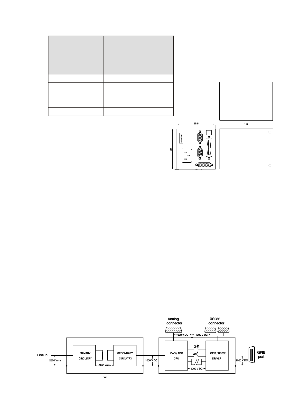
5 Dimensions
PSC-488 module and PSC-232 module:
89 x 85.5 x 118 mm, 0.8 kg
Enclosure: IP20
6 Specifications
6.1 Power
Range: 98-264 VAC 48-62 Hz
for DC-voltage contact factory
Power consumption: 10 W
Hold-up time: 300 ms, Vin = 230 VAC
6.2 EMC
Emission : EN 61000-6-3
EN 55022 B
Immunity : EN 61000-6-2
6.3 Isolation
Analog/logic in/outputs to case : 1000 V DC
GPIB or RS232 to case : 1000 V DC
Line input to case : 2500 V AC
••••••*
••
••
••
••••••
Dimensions PSC-232 and PSC-488 modules
6.4 Ambient temperature
Operating: 0 to 55 °C (Ext model)
Storage: -20 to +70 °C
6.5 Analog outputs
80 ms, Vin = 110 VAC
The analog outputs can be individually set on
0-5 V The settings can be reported.
Calibration is by software. Settings can be
saved in non-volatile memory. Analog in- and
outputs have a common zero
• 2 analog outputs with buffered 14 bit D AC
• Output range 0 to 5 V
• Full scale software adjustment > 200 mV
• Offset software adjustment > 200 mV
• Resolution 0.33 mV / 5 V output
• Linearity error 1 LSB
• TC typical 30 ppm / °C
Isolation schematic diagram
May 2008 MANUAL page 4
Page 6

DELTA ELEKTRONIKA BV PSC SERIES
6.6 Analog inputs
The analog inputs can be individually read.
Calibration is done by software. Settings
can be saved in non-volatile memory.
Analog in- and outputs have a common
zero
• Full scale software adjustment
• 2 x analog input channels with 16 bit
ADC Input range 0 to 5 V
• Offset software adjustment
• Resolution 0.1 mV / 5 V input
• Linearity error +/- 2 LSB
• TC typical 5 ppm / °C
Read Back Resolution
The read back resolution depends on the
voltage and current range of the power
supply that is used with the PSC.
Range Decimals
6.7 Status monitoring
The PSC provides TTL /CMOS compatible status
inputs for monitoring signal changes and fail signals
of the power-supply as CC mode, Current or
Voltage Limit, DC Fail, AC Fail and Over
Temperature. See power supply manual.
Status Weight Name
11 CC
2 2 LIM
3 4 DCF
4 8 ACF
516 OT
6 32 PSO
7 64 InpA
8 128 InpB
0 - 5.9999 4
6.000 - 59.999 3
60.000 - 599.99 2
Example with power supply SM52-30:
The voltage range is 52 V. After
programming the unit to 50 V, the read
back value has 3 decimals, see table;
V
readback = 50.000 V. The 3 digits after the
decimal point give a resolution of 1 mV.
This means that for 50 V the number of
steps is 50000. From the next table it can
be seen that the resolution is better than
15 bit.
Bit Steps
12 4096
13 8192
14 16384
15 32768
6.8 Logic inputs
The PSC-488 module and the PSC-232 module
provide two 1000 V opto isolated logic inputs, InpA
and InpB for custom use.
The inputs are 470 ohm, Logic high = 2.5 ... 8 V
(15 mA max), Logic low = 0 V.
The two inputs have a common zero.
The maximum reverse voltage = 6 V.
6.9 Logic outputs
The PSC-488 module and the PSC-232 module
also provide two opto isolated logic outputs for
custom use: OutA and OutB.
The opto coupler outputs have an open collector
and a common zero. The maximum voltage is 50 V
and the maximum current is 5 mA.
Total power dissipation = 150 mW.
16 65536
User logic in/outputs for external PSC-488 module
and PSC-232 module
Analog in/ outputs
page 5 MANUAL May 2008
Page 7

PSC SERIES DELTA ELEKTRONIKA BV
6.10 Led indicator
The PSC-232 module and the PSC-488 module have LEDs on the front panel.
LED PSC-232 module PSC-488 module
PWR
LSN
TLK
ERR
RDY
••
•
7 GPIB capabilities
The PSC-488 supports the following standard IEEE488.1-1987 capabilities.
ID code Capability
T6 Basic talker, Serial poll, Un address if MLA
L4 Basic listener, Un addressed if MTA
SH1 Source handshake
AH1 Acceptor handshake
SR1 Service request
Power on
•
•
•
Listener mode
Talker mode
Device in error
Device ready for
command.
•
•
•
•
•
RL0 Remote / local
PP0 Parallel poll
DC1 Device clear
DT0 Device trigger
C0 Controller
E2 Three state driver
7.1 Restrictions
Up to 15 devices can be connected to the IEEE 488
instrument bus (can be increased by with a bus
extender). The maximum cable length to connect a
group of instruments is 2 meters x number of devices
or 20 meters, whichever is less. Cable configurations
may be star, linear or a combination of the two. Each
of the devices must have a specific address code. The
PSC-488 module has a device address code switch on
the rear panel next to the GPIB connector. It has to be
set to the appropriate binary code for the desired
address.
•
•
GPIB CONNECTOR
May 2008 MANUAL page 6
Page 8

DELTA ELEKTRONIKA BV PSC SERIES
8 Switch settings
8.1 Address switch
When setting the address use any address from 1 up to 30.
The address is a 5 bit binary number which can be set with
switch A1 to A5.
Switch A1 is the LSB and switch A5 is the MSB.
For example address 1 is 00001 (A1 = on, A2-A5 = off) and
address 30 is 11110 (A1 = off, A2-A5 = on).
8.2 PORQS switch
Only for DPL mode.
A8
is the PORQS switch. With switch POSRQ in the ON position, not only a SRQ at power-on
but also the request for service capability is enabled.
8.3 DPL command switch
A7 is the language switch on PSC-488 models.
When the DPL switch is ON, the PSC is in PSC 44M emulation mode.
The switch OFF means the PSC is in PSC-488 mode, SCPI language.
8.4 RS232 communication switch
A6 is used on PSC-488 models only.
When the RS232 switch is ON, the PSC is in RS232 mode.
The switch OFF means the PSC is in GPIB mode.
8.5 Baudrate
For PSC-232 models the switches A7 and A8 are baudrate switches.
Baudrate A8 A7
Address switch
2400 off off
4800 off on
9600 on off
8.6 Factory pre-settings
PSC-488:
Address 8
SCPI Language
RQS 0
A1, A2, A3, A5, A6, A7, A8 = off
A4 = on
PSC-232
Channel 1
SCPI Language
9600 baud
A2, A3, A4, A5, A6, A7 = off
A1 and A8 = on
:
page 7 MANUAL May 2008
Page 9

PSC SERIES DELTA ELEKTRONIKA BV
9 Connections
9.1 RS232 Interface
Connector from PC:
D 9 F conn.
Pin 2 TXD
Pin 3 RXD
Pin 5 GND
Connector to next PSC:
D 9 M conn.
Pin 2 RXD
Pin 3 TXD
Pin 5 GND
For connection to the PC or to the next PSC use a 1:1 cable with 1 female and 1 male connector.
Do not use a null modem cable.
Baudrate : 2400 - 9600 baud
Databits : 8
Stopbits : 2
Paritybits : none
Signal level : -10 V to +10 V
Maximum cable length : 15 m
9.2 Pin assignment of the 15P connector
PIN DESCRIPTION PSC In/Output Abbreviation
1 Analog common Analog common AGND
2 Current Monitor Analog Input I MON
3 Current Programming Analog Output I PROG
4 Constant Current status Digital Input CC
5 Remote Shut Down logic output Digital Output RSD
6 Power sink overload Digital Input PSO 1)2)
7 Not Connected NC
8 Digital common Digital common DGND
9 Not Connected NC
10 Voltage Monitor Analog Input V MON
11 Voltage Programming Analog Output V PROG
12 Over Temperature Digital Input O.T. 1)
13 Limit Status Digital Input LIM 1)
14 DC Fail Digital Input DCF 1)
15 AC Fail Digital Input ACF 1)
9F Pole D connector 9M Pole D connector
15 pole D connector
1) Check the power supply manual if the power supply supports the status.
2) If an SM7020-D or SM3004-D is used in combination with a
PSC module, remove the jumper on P532 or otherwise the
autoranging will not work properly.
First remove the screws from the bottom and top of the PSC in
order to remove the cover from the cabinet. Then remove the
jumper on the PCB P532.
May 2008 MANUAL page 8
Page 10

DELTA ELEKTRONIKA BV PSC SERIES
10 Conventions
Angle brackets < > Indicate that words or characters enclosed in angular brackets
symbolize a program code parameter.
Brackets { } Brackets indicate one of the several parameters may be entered.
For example { 1|0|ON|OFF}.
Square brackets [ ] All items between square brackets are optional.
Boldface Boldface and computer font is used to show command syntax in the text.
Controller A computer used to communicate with an instrument.
Instrument A device that implements SCPI (PSC-488).
10.1 Frequently used ASCII symbols
Symbols DEC HEX Codes Display Description
EOT 4 04 \04 end of transmission
LF 10 0A \n line feed (command terminator)
CR 13 0D \r carriage return
ESC 27 1B \1B escape
WSP 32 20 \s space
10.2 Summary of Data types
Example NDEC Decimal
Digit character 0....9 8
Hexadecimal character 0..9 & A....F #hFA 250
Binary character 0 or 1 #b0101 5
String character 0....9 and A....Z
NDEC = Non-decimal HEX, OCT, BIN (Hexadecimal, Octal, Binary)
10.3 Booleans
A Boolean parameter is normally used to specify a binary condition which is either True or False.
Booleans can have one of the following values:
ON or 1 means condition is True.
OFF or 0 means condition is False.
Example: OUTputA ON or OUTputA 1.
10.4 Numerical data formats.
Symbol Meaning example
<NR1> Signed integer value 1234
<NR2> Floating point value without an exponent 12.345
page 9 MANUAL May 2008
Page 11

PSC SERIES DELTA ELEKTRONIKA BV
11 Installation of the PSC
When the External PSC module is used for the
first time, it must be configured and calibrated
together with the power supply. The card set
types are factory configured and calibrated.
11.1 PSC-488 module
This type of PSC is for rail or rack mounting, the
unit can be mounted to the rear side of the power
supply using a rail. Connect and install the PSC
as follows:
Connection of the PSC-488 module
• When used with a SM7020-D or with a SM3004-D
remove the link on P532 (see comment 2 on page 8)
• Set the address switches to 8
A1, A2, A3, A5 = OFF and A4 = ON.
• Set the GPIB communication switch A6 = OFF.
• Set SCPI language switch A7 = OFF.
• Set RQS switch A8 = OFF.
• Connect the 15 pole analog cable between the PSC and the power supply.
• Connect a GPIB cable between the PC and the PSC.
• Connect the line-cord.
• Switch the power supply to “programming” (see power supply manual).
• Go to section 12 of this manual.
11.2 PSC-488
This is a card set, mounted inside the power supply. Connect and install the PSC as follows:
• Set the address switches to 8
A1, A2, A3, A5 = OFF and A4 = ON.
• Set the GPIB communication switch A6 = OFF.
• Set SCPI language switch A7 = OFF.
• Set RQS switch A8 = OFF.
• Connect a GPIB cable between the PC and the PSC.
• Switch the power supply to “programming” (see power supply manual).
• Go to section 12 of this manual.
11.3 PSC-232 module
This type PSC is for rail or rack mounting, the unit can be mounted to the rear side of the power supply
using a rail. Connect and install the PSC as follows:
• When used with a SM7020-D or with a SM3004-D,
remove the link on P532 (see comment 2 on page 8)
• Set the DIP switch to channel (address) 1. A2, A3, A4, A5 = OFF and A1 = ON.
• Set the Baudrate switch to 9600 baud. A6, A7 = OFF and A8 = ON.
• Connect the 15 pole analog cable between the PSC and the power supply.
• Connect the 9 pole RS232 cable between the PC comport and the PSC.
• Connect the line cord.
• Switch the power supply to “programming” (see power supply manual).
• Start the program Cal232.exe (on the CD) and follow the instructions on the screen.
May 2008 MANUAL page 10
Page 12

DELTA ELEKTRONIKA BV PSC SERIES
11.4 PSC-232, P146 or P148
These are card sets, mounted inside the power supply.
Connect and install the PSC as follows:
• Set the DIP switch to channel 1. A2, A3, A4, A5 = OFF
and A1 = ON.
• Set the Baudrate switch to 9600 baud. A6, A7 = OFF and
A8 = ON.
• Connect the 9 pole RS232 cable between the PC comport
and the PSC.
12 Calibration of the PSC
For easy calibration, a CD with a calibration program is supplied with the PSC-488 and PSC-232. You
can download the latest version from Internet www.DeltaPowerSupplies.com
file supplied with the calibration program.
. First read the “ReadMe”
12.1 Configuration setting
•
Switch on the power of the power supply.
• Run the LabView program “PSC488_v61.exe”.
• Select “PSC488 Calibration.vi”.
• Click “OK”.
• Select tab “Start”.
• Select “PSC address” 8.
• Set the “Power supply voltage range”.
• Set the “Power supply current range”.
• When password protected, enable “Reset calibration”.
• Click “run continuously” in menu bar:
• Click “Config”.
• If configuration fails, repeat from configure.
• When configuration is successful, the program.
switches automatically to tab 1.
Start screen: Voltage and current configuration
12.2 Voltage DAC Offset calibration
•
Connect a digital mV meter to the output terminals of
the power supply.
• Click “Continue”.
The program sets the current and the voltage.
The “Actual offset” will be displayed.
• Enter the DVM value in mV.
• Click “Continue”.
• When calibration fails, repeat.
• When calibration is successful, the program switches
automatically to tab 2.
Voltage calibration connection
Screen 1: Voltage DAC Offset calibration
page 11 MANUAL May 2008
Page 13

PSC SERIES DELTA ELEKTRONIKA BV
12.3 Voltage DAC gain calibration
•
Switch the digital voltage meter to the right range
(maximum output voltage of the power supply).
• Click “Continue”.
• Enter the DVM value.
• Click “Continue”.
• When calibration fails, repeat.
• When calibration is successful, the program switches
automatically to tab 3.
Screen 2: Voltage DAC gain calibration
12.4 Voltage ADC Offset calibration
•
Switch the digital voltage meter to the right range.
See “Set voltage”.
• Click “Continue”.
• Enter the DVM value.
• Click “Continue”.
• When calibration fails, repeat.
• When calibration is successful, the program switches
automatically to tab 4.
12.5 Voltage ADC gain calibration
•
Switch the digital voltage meter to the right range
(maximum output voltage of the power supply).
• Click “Continue”.
• Enter the DVM value into “Input” control.
• Click “Continue”.
• Check “Measure new voltage”.
• Click “Continue”.
• When calibration fails, repeat.
• When calibration is successful, the program switches
automatically to tab 5.
12.6 Current DAC Offset calibration
The program has set the voltage and current to zero, so
you can safely change the connections of the power
supply.
Screen 3: Voltage ADC offset calibration
Screen 4: Voltage ADC gain calibration
• Connect a shunt and a D.V.M. (or zero flux ampere
meter) on the output terminals.
• Click “Continue”.
• The program sets the current and the voltage.
May 2008 MANUAL page 12
Current calibration connection
Page 14

DELTA ELEKTRONIKA BV PSC SERIES
• Measure the shunt voltage with the D.V.M. and
calculate the current.
Enter the value.
• Click “Continue”.
• Click "Continue" to set the output to zero.
• When calibration fails, repeat.
• When calibration is successful, the program switches
automatically to tab 6.
Screen 5: Current DAC offset calibration
12.7 Current DAC gain calibration
The program has set the voltage and current to zero, so
you can safely change the connections of the power
supply.
• Connect a shunt and a D.V.M. (or zero flux ampere
meter) on the output terminals.
• Click “Continue”.
The program sets the current and the voltage.
• Measure the shunt voltage with the D.V.M. and
calculate the current.
• Enter the value.
• Click “Continue”.
• Click "Continue" to set the output to zero.
• When calibration fails, repeat.
• When calibration is successful, the program
switches automatically to tab 7.
12.8 Current ADC offset calibration
•
Switch the digital ampere meter to the right range.
See “Set current”.
• Click “Continue”.
• Enter the DVM value.
• Click “Continue”.
• Click "Continue" to set the output to zero.
• When calibration fails, repeat.
• When calibration is successful, the program
switches automatically to tab 8.
Screen 6: Current DAC gain calibration
Screen 7: Current ADC offset calibration
page 13 MANUAL May 2008
Page 15

PSC SERIES DELTA ELEKTRONIKA BV
12.9 Current ADC gain calibration
•
Switch the digital ampere meter to the right range.
See “Set current”.
• Click “Continue”.
• Enter the DVM value.
• Click “Continue”.
• Check “Measure new current”.
• Click “Continue”.
• When calibration fails, repeat.
• When calibration is successful, the program
switches automatically to tab 9.
Screen 8: Current ADC gain calibration
12.10 Change IDN string
The IDN string can be changed. The suffix of the PSC
is entered in field 2. Field 4 is reserved for a custom
string. This calibration program enters the calibration
date in this field.
• Select a button INT,EXT, P146 or P148.
The red characters are the new IDN text.
• Click "Continue".
• Reset the PSC
(Switch the power of the PSC off.
Wait untill all LEDs are off
Switch on the PSC power).
• Click "Continue".
• The new IDN string is displayed in the black
indicator “New IDN string”.
End of calibration.
Screen 9: Change IDN string
May 2008 MANUAL page 14
Page 16

DELTA ELEKTRONIKA BV PSC SERIES
13 Power on Settings
When shipped, the PSC-488 module and the PSC-232 module are set to the configuration listed in table.
All configurable parameters can be changed and stored by the user.
Function Command Value
Voltage range
Current range
Text field #2 in IDN string
Text field #4 in IDN string
Password
SOurce:VOltage:MAximum
SOurce:CUrrent:MAximum
TYpe
CUstom
PAssword
Remote shut down 0
Remote 1
At power-on the Service Request Enable Register and the Standard Event Status Enable Register are
cleared.
5
5
“EXT” | “INT” | “P146” | “P148”
“Not Calibrate”
“Default”
page 15 MANUAL May 2008
Page 17

PSC SERIES DELTA ELEKTRONIKA BV
14 Languages
This section describes the operation of the three groups of commands.
The Groups are: Delta Programming Languages DPL, Standard Commands Programmable Instruments
SCPI, and Common commands.
• Delta Programming commands is a PSC 44M compatible language. With the DIP switch A8 ON
and A7 OFF the DPL is active. The DPL mode emulates the commands of the old PSC 44M and
the 12 bit DAC and ADC.
• Common commands are mnemonic commands beginning with a star. The query commands are
followed by a question mark. The common commands are defined in the IEEE488.2 standard and
control status reporting, synchronization and conditions of the power supply and the PSC-488.
• Standard Commands for Programmable Instruments SCPI.
These commands are used to configure and calibrate the PSC, to set voltage and current and to
read back voltage,current and status of the Power Supply.
Note: Terminator for all commands is LF.
14.1 Delta Programming Commands
MNEMONICS FUNCTION
SA
SB
FU
FI
U
I
ERR?
ID?
MA?
MB?
SCPI
Step mode A channel (voltage)
Step mode B channel (current)
Input maximum voltage of the power supply
Input maximum current of the power supply
Set output voltage of the power supply
Set output current of the power supply
Report the last error
Report the Identify of the PSC
Read the measured output voltage of the power supply
Read the measured output current of the power supply
Switch to the SCPI parser
PSC 44 emulating mode.
The PSC-488 emulates in this mode the PSC 44 language including the 14 to 12 bit conversion. The calibration is by
the PSC-488 software. To calibrate the PSC-488 set the DIP switch A6 and A7 to OFF prior to using the calibrating
program (See chapter calibration) and after the calibration the DIP switch must be set to A7 = ON (Delta
Programming Languages).
For more details read the PSC 44M manual.
When in SCPI mode, the command “DPL” switches the PSC-488 to DPL mode.
May 2008 MANUAL page 16
Page 18

DELTA ELEKTRONIKA BV PSC SERIES
14.2 IEEE488.2 Common Commands.
The mnemonic common commands have three letters and begin with a star, the query commands are
followed by a question mark (?). Common commands are defined by the IEEE STD 488.2-1987 standard
and control status reporting, synchronization, power-on conditions and stored operating parameters of
the PSC-488.
The PSC-488 contains the following common commands.
MNEMONICS Description
*IDN?
*RST
*TST?
*OPC
*OPC?
*WAI
*CLS
*ESE
*ESE?
*ESR?
*SRE
*SRE?
*STB?
*SAV
*RCL
14.2.1 Status reporting
Identification query.
Device Reset command.
Self test query.
Operation complete command.
Operation complete query.
Wait to continue command.
Clear status command.
Standard event status enable command.
Standard event status enable query.
Standard event status register query.
Service request enable command.
Service request enable query.
Read status byte query.
Save calibration values to non-volatile memory.
Recall values from non-volatile memory.
Only PSC-488
•
•
•
•
•
•
•
•
•
•
The status structure of the PSC-488 is used to reflect the power supply condition and to report all kind of
events that have happened. The various status models are ultimately reported in the Status Byte
Register, giving a complete organized status of the power supply. Status model, registers and queues
are reported in one of the summary bits of the Status Byte Register. The Service Request Enable
Register selects which Status Byte bits will cause a Service Request (SRQ) on the GPIB.
From the Status Byte Register, which is returned as response to a serial poll from a controller, it is
always possible to trace back the event that caused the corresponding summary bit to be set.
The diagram shows the interrelations.
14.2.2 *SRE
The Service Request Enable Command specifies the bit values of the Service Request Enable Register.
This register determines which conditions from the Status Byte Register will cause a Service Request
(SRQ) are summarized in the Master Summary Status -MSS- of the Status Byte Register.
A bit value 1 in the Service Request Enable Register selects the corresponding Status Byte Register
condition. The bit value of bit 6 (RQS/MSS) is ignored. The command parameter is specified as a
decimal using the <Nrf> format; when rounded to an integer value and expressed base 2 (binary),
the parameter represents the bit value of the Standard Event status Enable Register. Alternatively, the
command parameter may use a non-decimal numeric format (hexadecimal, octal or binary) to express
the register’s bit setting.
*SRE?
The Service Request Enable Query returns a decimal value, which expressed in base 2, reflects the bit
values of the Service Request Enable Register. Bit 6 is always set to 0.
page 17 MANUAL May 2008
Page 19

PSC SERIES DELTA ELEKTRONIKA BV
14.2.3 Register diagram
May 2008 MANUAL page 18
Page 20

DELTA ELEKTRONIKA BV PSC SERIES
14.2.4 *STB?
The Read Status Byte Query reports the contents of the Status Byte Register. The register contains the
summary status of all overlaying registers and status queues. When the Status Byte Register is read by
a serial poll from the GPIB, the RQS bit is returned on bit position 6. The *STB? query returns the MSS
bit on bit position 6. Reading the status byte by a serial poll or with the *STB? query does not affect its
contents. The only exception to this rule is the RQS bit. This bit is always cleared after a serial poll. The
other bits are cleared only when the overlaying status structure, which caused the summary bit or with
*CLS.
Bit MNE Description Status Byte Register
0 DSB
1 DEB
2 Not used
3 Not used
4MAV
5 ESB
6MSS
6 RQS
7 Not used
Device
Status
Device
Extended
Status
Message
Available
Event
Summary Bit
Master
Summary
Status.
Requested
Service.
Contains the summary of the Device Status register.
Contains the summary of the Device Extended status register.
Only used by power supply with internal CPU (SM6000)
Indicates the ‘non-empty’ status of the Output Queue; this bit is set
True when at least one byte is available in the queue. It is set to
False when the Output Queue is empty.
Contains the summary of the Standard Event Status register.
Returned as a response to the *STB? query. Indicates that there is
an event that caused the device to request for service. The MSS bit
is cleared when the events in the overlaying status structure that
caused the service request, are cleared.
Sent as a response to a serial poll over the GPIB. Indicates that the
device requested for service; this means that a SRQ message was
issued on the GPIB. It differs from the MSS bit in the fact that the
RQS bit is cleared after the serial poll. It is only set True again
when a new event occurs that requires service.
For each status structure there is an Event register, that reflects the events themselves, and an Event x
Enable
• Register. The Event Enable register selects which events are summarized into the Status Byte
Register.
• The Status Byte Register can be read by either Serial Poll or by the *STB? query. The Status Byte
Register is cleared only by clearing its overlaying structures.
• The Service Request Enable Register allows to select particular bits from the Status Byte to generate
a Service Request (SRQ) on the GPIB.
page 19 MANUAL May 2008
Page 21

PSC SERIES DELTA ELEKTRONIKA BV
14.2.5 *CLS
This Clear Status Command clears the device’s status structures.
• All Event Registers summarized in the Status Byte.
• The Standard Event Status Register.
• Sets the device into the Operation Complete Command Idle State.
• Sets the device into the Operation Complete Query Idle State.
Note:
The *CLS command does not effect the Output Queue. However if there is data in the Output Queue and
a *CLS command immediately followed by a Program Message Terminator is received, the Output
Queue will cleared.
Standard Event status Register
This register contains the events that are standardized by IEEE488.2.
Common Commands are provided to access the values associated with the Standard Event Status.
14.2.6 *ESE
The Standard Event Status Enable Command specifies the bit values of the Standard Event Status
Enable Register. This register determines which events from the standard Event Status Register are
summarized in bit 5, the Event Summary Bit - ESB - of the Status Byte Register.
A bit value 1 in the Standard Event Status Enable Register selects the corresponding event bit in the
Standard Event Status Register to be reported in the Event Summary Bit.
The command parameter is specified as a format, a decimal integer value from 0 to 255 and expressed
base 2 (binary), the parameter represents the bit value of the Standard Event Status Enable Register.
*ESE?
The Standard Event Status Enable Query returns a decimal value, which expressed in base 2 reflects
the bit values of the Standard Event Status Enable Register.
14.2.7 *ESR?
The *ESR? query causes the Standard Event Status Register is cleared.
Example:
send —-> *ESR?
read <—- 28 equals the binary value 00011100
The bits 4 (EXE), 3 (DDE) and 2 (QYE) are set. This means that an Execution Error, a Device
Dependent Error and a Query Error has occurred since the last time this register was read.
Note:
The next *ESR? query will return a zero value, if no new events have occurred.
May 2008 MANUAL page 20
Page 22

DELTA ELEKTRONIKA BV PSC SERIES
BIT MNE Name Description of the standard Event Status Register
0 OPC Operation complete indicates whether an operation is completed or is still pending.
1 QRC Request Control Not implemented. Always set to 0.
This error will occur when the Message Exchange Protocol is
violated. For example, when a query was sent to the instrument
and subsequently a new command is sent without first having read
the entire response data from the previous query. Also trying to
read data from the PSC-488 without first sending a query to the
instrument will cause this error.
2 QYE Query Error
In general a query error is reported because of:
• incorrect query response handling.
• an un terminated or interrupted action.
• a buffer deadlock because the input buffer and output
queue are overflown.
• indefinite response from the PSC-488.
3 DDE
4 EXE Execution Error
5 CME Command Error
6 URQ User Request Indicates that the user has requested for a service.
7 PON Power-on
14.2.8 DSE
Device Status Enable
This command specifies the bit values of the Device Status Enable Register. This register determines
which events from the Device are summarized in bit 7 of the Status Byte Register. A bit value 1 in the
DSE selects the associated bit in the DSR (Device Status event Register) to be reported in Bit 0 of the
Status Byte Register, the Device Summary Status bit 0.
DSE?
The Device Status Enable query returns a decimal value, which expressed in base 2, reflects the bit
values of Device Status Enable Register. The returned value is a NR1 response data type.
Device Dependent
Error
This error indicates that the PSC-488 could not properly complete
some device specific operations.
indicates that a syntactical valid program message is received that
can not be executed due to some device specific conditions.
This error indicates that the instrument detected a syntax or
semantic error.
Indicates that the device’s has been turned off and on since the
last time that the register was read or cleared.
14.2.9 DSR?
The Device event Status Register captures transitions in its condition register. An event bit becomes true
when the associated condition bit makes a logical 0 to 1 or 1 to 0 transition. The command DSR? returns
a decimal value, which expressed in base 2, reflects the bit values of the Device event Status Register.
Execution of this query causes the Device Status Enable Register to be cleared. The returned value is a
NR1 response data type.
page 21 MANUAL May 2008
Page 23

PSC SERIES DELTA ELEKTRONIKA BV
14.2.10 DSC?
The Device Status Condition register contains the power supply’s status, and returns a decimal value,
which expressed in base 2, reflects the bit values of the Device Status. Execution of this query will not
clear this register. The returned value is a NR1 response data type. See the power supply manual to
check which statuses are available
BIT MNE Description Device Status Condition register
0 CC Constant Current
1 LIM Limit
2 DCF DC Fail
3 ACF AC Fail
4 O.T. Over Temperature
5 PSO Power Sink Overload
6 InpA (CCR) User input A (CCR when used in a power supply with internal CPU)
7 InpB (CVR) User input B (CVR when used in a power supply with internal CPU)
14.2.11 DEE
This register is only available when a power supply is used with an internal CPU.
Device Extended status Enable. This command specifies the bit values of the Device Extended status
Enable Register. This register determines which events from the Device Extended status Register are
summarized in bit 1 of the Status Byte Register. A bit value 1 in the Device Extended status Enable
Register selects the corresponding bit in the Device Extended status Register to be reported in Bit 1 of
the status byte, the Device Summary Extended status bit.
DEE?
The Device Extended status Enable query returns a decimal value, which expressed in base 2, reflects
the bit values of Device Extended status Enable Register. The returned value is a NR1 response data
type.
Bit MNE Description Device Extended status condition Register
0 HOT High temperature
1 INTL Interlock
2 VLIM Voltage limit
3 ILIM Current limit
4 CV Constant voltage mode
5 OUTP Output on
6 RSD Remote shut down
7 FPL Front panel lock
14.2.12 DER?
The Device Extended status Register contains the power supply Extended status change , and returns a
decimal value, which expressed in base 2, reflects the bit values of the Device Extended status register.
Execution of this query causes the Device Extended status Register to be cleared. The returned value is
a NR1 response data type.
14.2.13 DEC?
The Device Extended status Condition register contains the power-supply status, and returns a decimal
value, which expressed in base 2, reflects the bit values of the register. The returned value is a NR1
response data type. See the power supply manual to check which statusses are available.
May 2008 MANUAL page 22
Page 24
DELTA ELEKTRONIKA BV PSC SERIES
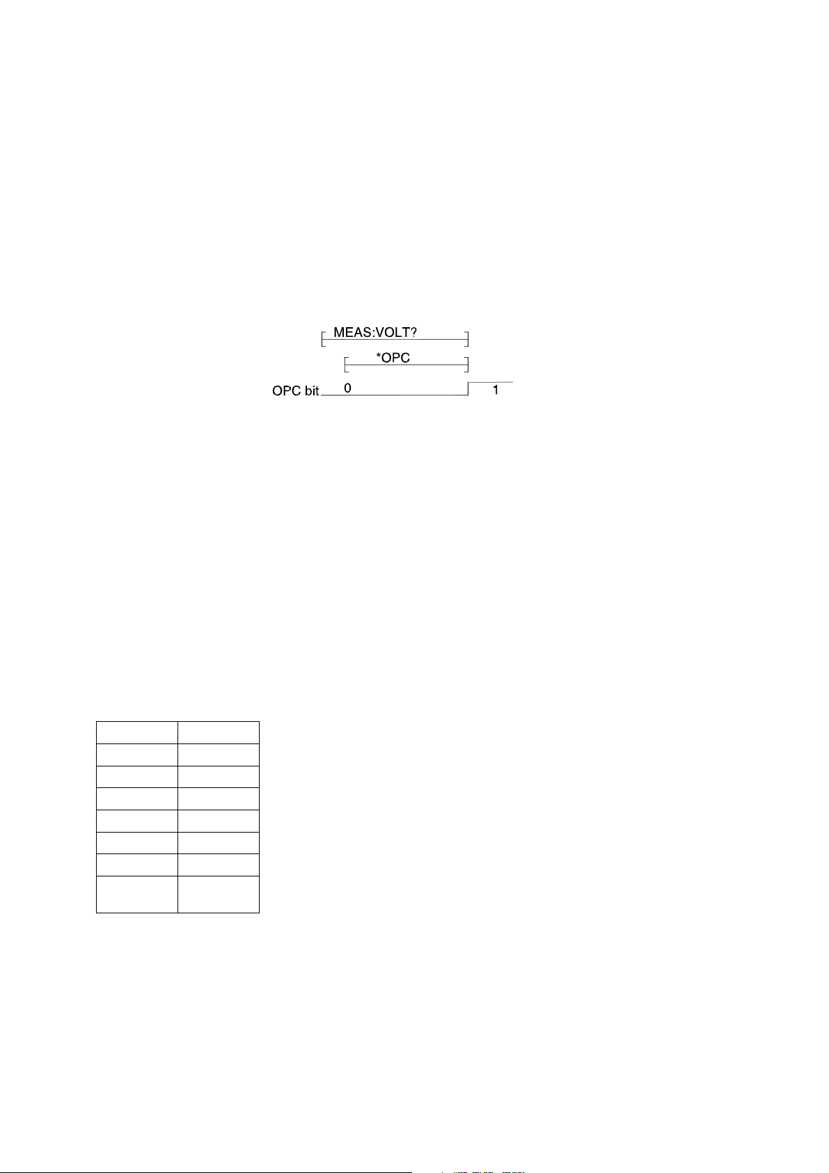
14.2.14 *OPC
The Operation Complete Command allows for synchronization between a controller and several devices.
It causes the instrument to set the Operation Complete Command -OPC- bit in the Standard Event
Status Register to be set true when all selected pending operations have been finished. This implies that
all device operations initiated by previous programming commands have been entirely completed or
aborted.
Example:
Send —-> MEAS:VOLT?
Send —-> *OPC
The timing diagram related to the internal execution of these commands is shown in the following figure:
There are two methods of synchronization between application programs and the PSC-488:
• Use the OPC event bit to generate a Service Request. During the instrument operation, the
application program can perform other tasks if the Service Request is used as interrupt.
• Read the *OPC bit (bit 0) from the standard event register using the common query *ESR?.
Wait until the OPC bit becomes set to true.
*OPC?
The Operation Complete Query is a method for synchronization. The Operation Complete Query places
an ASCII character"1" in the device Output Queue when all pending operations have been finished.
14.2.15 *RST
The *RST command resets the device dependent functions except for memorized configuration settings,
protected settings and calibration data.
Voltage 0 V
Current 0 A
Output Disable
RSD off
REM on
REM CV on
REM CC on
Front
panel
Unlock
page 23 MANUAL May 2008
Page 25

PSC SERIES DELTA ELEKTRONIKA BV
14.2.16 *TST?
The Self-Test Query causes the device to execute an internal self-test and reports detected errors.
The PSC-488 will output the ASCII character 0 (20 hex) when the test is passed without failures.
14.2.17 *WAI
The Wait-to-Continue Command is useful after an overlapped command to force sequential execution.
The *WAI command will prevent the instrument from executing any further command or query until it has
finished the actions started by the overlapped command.
14.2.18 *SAV
Saves settings and calibration data in non-volatile memory registers. It is possible to protect the
calibration data with a password. Normally the password is “DEFAULT” and not protected.
After the command password<wsp>DEFAULT,<new_password> the new password is active and the
*SAV works only with the password parameter *SAV <new_password> .
14.2.19 *RCL
Recalls the settings and calibration data previously stored with the *SAV command.
14.2.20 *IDN?
The Identification Query is used to identify the PSC within a system. The response to the *IDN? is an
<instrument_identifier> which is organized into four fields, mutually separated by commas (2C-hex).
Field 1 Manufacturer
Field 2 Model Version
Field 3 Serial number
Field 4 Custom string
The maximum number of characters is 72.
Note:
The syntax for the *IDN? response is Arbitrary ASCII Response Data. The IEEE488.2 standard requires
this data type to be terminated with a Response Message Terminator. Therefore, controllers should send
the *IDN? query as the last query message unit in a terminated program message. If not, the device will
generate a Query Error and will not send the response to the subsequent queries.
The following documents will assist you with programming the IEEE488 interface:
Standard Codes, Formats, Protocols and Common Commands for use with IEEE Std 488.1-1987, IEEE
Standard digital interface for programmable instrumentation, IEEE std 488.2-1992 , Published by the
Institute of Electrical and Electronics Engineers),
345 East 47th street, New York, NY 10017-2394, USA
ISBN 1-55937-238-9
DELTA ELEKTRONIKA BV DELTA ELEKTRONIKA BV
PSC-488 module V 1.0.0, PSC-232 V 1.0.0,
123456789012, 123456789012,
TST. 05\03\01 30 V / 10 A
May 2008 MANUAL page 24
Page 26

DELTA ELEKTRONIKA BV PSC SERIES
14.3 SCPI commands
14.3.1 SOurce:VOltage:MAximum
14.3.2 SOurce:CUrrent:MAximum
These commands are used to enter the maximum voltage and maximum current range of the used
power supply. For example, the Delta power supply model SM35-45 has a range of 35 volt and 45
ampere. The SOur:VOlt:MAx<wsp>35 and the SOur:CUrr:MAx<wsp>45 have to be given before the
voltage and current set commands. Save the configuration values in non-volatile memory with the *SAV
command. The next time settings will automatically recalled at power on.
SOur:VOlt:MAx? and SOur:CUrr:MAx? read back the voltage and current settings.
14.3.3 CAlibration:CUrrent:OFfset
CA:CU:OF<wsp><NR1>
Used to calibrate the zero-offset of the current programming.
14.3.4 CAlibration:CUrrent:OFfset?
Reads-back the present offset calibration value of the current programming.
14.3.5 CAlibration:CUrrent:GAin
Used to calibrate the full-scale of the current programming.
14.3.6 CAlibration:CUrrent:GAin?
Reads-back the present full scale calibration value of the current programming.
14.3.7 CAlibration:VOltage:OFfset
Used to calibrate the zero-offset of the voltage programming.
CAlibration:VOltage:OFfset?
Reads-back the present offset calibration value of the voltage programming.
14.3.8 CAlibration:VOltage:GAin
Used to calibrate the full-scale of the voltage programming.
CAlibration:VOltage:GAin?
Reads-back the present full-scale calibration value of the voltage programming.
14.3.9 CAlibration:CUrrent:MEasure:OFfset
Used to calibrate the zero-offset of the current monitoring.
CAlibration:CUrrent:MEasure:OFfset?
Reads-back the present offset calibration value of the current monitoring.
14.3.10 CAlibration:CUrrent:MEasure:GAin
Used to calibrate the full-scale of the current monitoring.
CAlibration:CUrrent:MEasure:GAin?
Reads-back the present full scale calibration value of the current monitoring.
page 25 MANUAL May 2008
Page 27

PSC SERIES DELTA ELEKTRONIKA BV
14.3.11 CAlibration:VOLTage:MEASure:OFFSet
Used to calibrate the zero-offset of the voltage monitoring.
CAlibration:VOltage:MEASure:OFfset?
Reads-back the present offset calibration value of the voltage monitoring.
14.3.12 CAlibrate:VOltage:MEasure:GAin
Used to calibrate the full-scale of the voltage monitoring.
CAlibrate:VOltage:MEasure:GAin?
Reads-back the present full scale calibration value of the voltage monitoring.
14.3.13 PAssword
From factory, the password is set to “DEFAULT” and *SAV can be used without parameter.
With the command PAssword<wsp>DEFAULT,<New_password> the protection is activated.
“DEFAULT” is the factory default string, <New_password> is the new password.
The string is maximum 8 characters and is not case sensitive. Execution of the *SAV command without
valid password causes an execution error 15 (Illegal password).
A few examples:
PA DEFAULT,MYPASSW<LF>
Changes the factory default password into a new password.
After this command the *SAV command works only with a valid password as parameter.
The command:*SAV MYPASSW<LF>.
PA <current_password>,<new_password>
Changes the current password into a new password.
PA MYPASS,DEFAULT
Changes the current password into the factory default. Protection is disabled.
PAssword?
This query returns a 0 if the access is not protected. Otherwise a 1 is returned when the acces is
protected with a password.
Forgotten password. With the command PAssword:Reset or abbriviated PA:R the PSC comming into a
non calibrated state and the password are set to “DEFAULT”.
May 2008 MANUAL page 26
Page 28

DELTA ELEKTRONIKA BV PSC SERIES
14.3.14 SOurce:FUnction:RSD<wsp><boolean>
The command SOurce:FUnction:RSD<wsp>{ON|1}or abbreviated SO:FU:RSD<wsp>{ON|1} disables
the output of the power supply. The command SOurce:FUnction:RSD<wsp>{OFF|0}or abbreviated
SO:FU:RSD<wsp>{OFF|0} enables the output again.
SOurce:FUnction:RSD?
The query SOurce:FUnction:RSD? or abbreviated SO:FU:RSD? returns 1 when the power supply is
disabled. Otherwise a 0 is returned.
14.3.15 SOurce:FUnction:OUtA<wsp><boolean>
The command SOurce:FUnction:OUtA<wsp>1 or abbreviated SO:FU:OUA<wsp>1 sets the open
collector output A of the PSC-488 to 1.
The command SO:FU:OUtA<wsp>0 sets the open collector output A of the PSC-488 to 0.
SOurce:FUnction:OUtA?
The query SOurce:FUnction:OUtA? or SO:FU:OUA? returns 0 if the digital output A is set to 0.
Otherwise , a 1 is returned.
14.3.16 SOurce:FUnction:OUtB <wsp> <boolean>
The command SOurce:FUnction:OUtB<wsp>1or abbreviated SO:FU:OUB<wsp>1 set the open collector
output B of the PSC-488 to 1.
The command SO:FU:OUA<wsp>0 set the open collector output B of the PSC-488 to 0.
SOurce:FUnction:OUtB?
The query SOurce:FUnction:OUtB? or SO:FU:OUB? returns 0 if the digital output B is set to 0.
Otherwise , a 1 is returned.
14.3.17 SOurce:FUnction:OUTP<wsp>{ON|OFF}
The command SOurce:FUnction:OUTP {on|off} or abbreviated SO:FU:OUTP {on|off} enables (on) or
disables (off) the output of the power supply.
SOurce:FUnction:OUTP?
The query SOurce:FUnction:OUTP? Or SO:FU:OUTP? Returns O when the output is disabled, or 1
when the output is enabled.
14.3.18 SOurce:FUnction:FRontpanel Lock
The command SOurce:FUnction:FRontpanel<wsp>{Lock|Unlock} or SO:FU:FR<wsp> {L|U} locks or
unlocks the front panel pushbuttons. See the power supply manual for details.
SOurce:FUnction:FRontpanel:Lock?
The query SOurce:FUnction:FRontpanel:Lock? Or SO:FU:FR:L? Returns 1 when the front panel is
locked. Otherwise a 0 is returned.
14.3.19 REMote and LOCal
The command REMote switches the power supply to remote-control. The command LOCal switches the
power supply back to manual control.
On some power supplies the selection Remote or Local is done by switches on the power supply itself.
On these power supplies the commands REmote and LOcal have no effect.
page 27 MANUAL May 2008
Page 29

PSC SERIES DELTA ELEKTRONIKA BV
REMote?
The query REMote? returns 0 when the power-supply in local mode. and in remote mode, a 1 is
returned.
LOCal
Warning: After the command LOCal, the power supply will return to the potentiometers settings on the
front panel.
Example: If the front-panel voltage potentiometer is set to 35 volt, the power supply output will go to 35V
after the command LOCal. Set the potmeters for voltage and current on the front panel to a safe value
prior to using the LOCal and REMote commands.
REMote:CV
When the programming switch 2 of ‘SW A’ are set to on, the command REM:CV switches the power
supply to voltage remote-control. The command LOC:CV switch the power supply back to manual
voltage control.
On some power supplies the selection Remote or Local is done by switches on the power supply itself.
On these power supplies the command REMote :CV has no effect.
REMote:CV?
The query REM:CV? returns 0 when the power supply in voltage local mode and in voltage remote
mode, a 1 is returned.
LOCal:CV
Warning: After the command LOC:CV, the power supply will return to the potentiometer setting on the
front panel (Also see the LOCal command).
REMote:CC
The command REM:CC switches the power supply to current remote-control. The command LOC:CC
switch the power supply back to manual current control.
On some power supplies the selection Remote or Local is done by switches on the power supply itself.
On these power supplies the command REMote :CC has no effect.
REMote:CC?
The query REM:CC? returns 0 when the power supply in current local mode. and in current remote
mode, a 1 is returned.
LOCal:CC
Warning: After the command LOC:CC, the power supply will return to the potentiometer setting on the
front panel. (Also see the LOCal command).
14.3.20 SOurce:CUrrent <wsp>
This command sets the output current of the power supply. The mode of operation depends upon the
load.
SOurce:CUrrent?
This query returns the present setting of the current.
May 2008 MANUAL page 28
Page 30

DELTA ELEKTRONIKA BV PSC SERIES
14.3.21 SOurce:VOltage <wsp>
This command sets the output voltage of the power supply. The mode of operation depends upon the
load.
SOurce:VOltage?
This query returns the present setting of the voltage.
Note that both voltage and current have to be programmed. It is necessary that the values of both
current and voltage are non zero, otherwise the power supply can not function properly. If zero volts is
programmed, then the current is limited to zero. If zero current is programmed, then the voltage will not
rise!
14.3.22 MEasure:VOltage?
This query returns the voltage measured at the power supply sense terminals.
14.3.23 MEasure:CUrrent?
This query returns the current delivered by the power supply.
Wait for a response from the power supply because it needs time to collect data and send it to the
computer.
Note:
When you write a program, you have to take care of the timing.
The ADC needs some time to measure the voltage or current.
See example programs on www.DeltaPowerSupplies.com.
14.3.24 CH
The channel command CH<wsp>n is the first command that should be executed to enable the
PSC-232xxx type with that channel number. Each unit must have a unique channel number between 0
and 30. The channel can be set with the DIP switch on the front panel of the PSC-232 module or on the
back side of an power supply.
CH?
The command CH? Reads the channel number of the active PSC-232 and communicates this back to
the computer.
14.3.25 Help?
The query HELP? returns a list of PSC commands.
14.3.26 SEnse:DIgital:DAta?
The Device Status Condition register contains the power supply status and returns a decimal value,
which expressed in base 2, reflects the bit values of the register. The returned value is a NR1 response
data type. See the power supply manual if the status available.
14.3.27 SEnse:DIgital:EXtendeddata?
The Device Extended status Condition register contain the power supply status and returns a decimal
value, which expressed in base 2, reflects the bit values of the register. The returned value is a NR1
response data type. See the power supply manual if the status available.
14.3.28 SEnse:DIgital:SWitch?
The Digital switch Condition register contain the power supply DIP switch status and returns a decimal
value, which expressed in base 2, reflects the bit values of the register. The returned value is a NR1
response data type. See the power supply manual if the DIP switch status is available.
page 29 MANUAL May 2008
Page 31

PSC SERIES DELTA ELEKTRONIKA BV
14.3.29 CU
With the CU command you can change the custom string of the identity string. See chapter 14.2.20.
The string must have 15 characters including the <lf> and is send via RS232.
Some examples:
CU<WSP>CAL. 01-02-2003 Calibration date
CU<WSP>SM 70-20 no 007 Power supply type and inventory number
After this command you can check it with query *IDN? to display the identify string.
With *SAV you can store the new information in non volatile memory.
May 2008 MANUAL page 30
Page 32

DELTA ELEKTRONIKA BV PSC SERIES
15 Error numbers
There are four groups of standardized errors, which are reported in the Standard Event Status and in the
Error/Event Queue, namely:
Classification
Command Error bit 5 - CME
Execution Error bit 4 - EXE
Device-Specific Error bit 3 - DDE
Query Error bit 2 - QYE
15.1 Command Error
This error indicates that the instrument detected a syntax or semantic error.
15.2 Execution Error
This error indicates that a syntactical valid program message is received that can not be executed due to
some device specific conditions.
15.3 Device specific Error
This error indicates that the PSC-488 could not properly complete some device specific operations.
15.4 Query Error
Standard Event
Register
This error will occur when the Message Exchange Protocol is violated.
For example, when a query was sent to the instrument and subsequently a new command is sent
without first having read the entire response data from the previous query. Also trying to read data from
the PSC-488 without first sending a query to the instrument will cause this error.
In general a query error is reported because of:
• Incorrect query response handling.
• An unterminated or interrupted action.
• A buffer deadlock because the input buffer and output queue are overflown.
• Indefinite response from the PSC-488.
Error number
1 Syntax error
2 Channel-number error
3 Numerical-value error
4 Command without full-scale
5 Maximum voltage range error
6 Maximum current range error
7 Data out of range
8...12, 16 Non volatile memory error
13 Checksum error
14 Overflow
page 31 MANUAL May 2008
Page 33

PSC SERIES DELTA ELEKTRONIKA BV
15 Illegal password
17 Invalid character
18 Not connected with PSU
19 Command not support, wrong configuration
16 Software examples and programs
Files on CD ROM or web site:
• Datasheet
• Manual
• RS232 and GPIB Calibration Program
• IBIC test scripts
• Labview VI for PSC-232 and for PSC-488
WEEE (Waste Elec trical & Elec tronic Equipment)
Correct Disposal of this Prod uct
Ap pli ca ble in the Eu ro pean Union.
This mark ing shown on the prod uct, its packing or its literature in dicates that it shoul d not be
disposed with other wastes at the end of its work ing life, but shoul d be col lected sep arately to
re cy cle it re spon si bly to pro mote the sus tain able re use of ma te rial re sources.
May 2008 MANUAL page 32
 Loading...