

Page 1
Evaluation Procedure
r
r
t
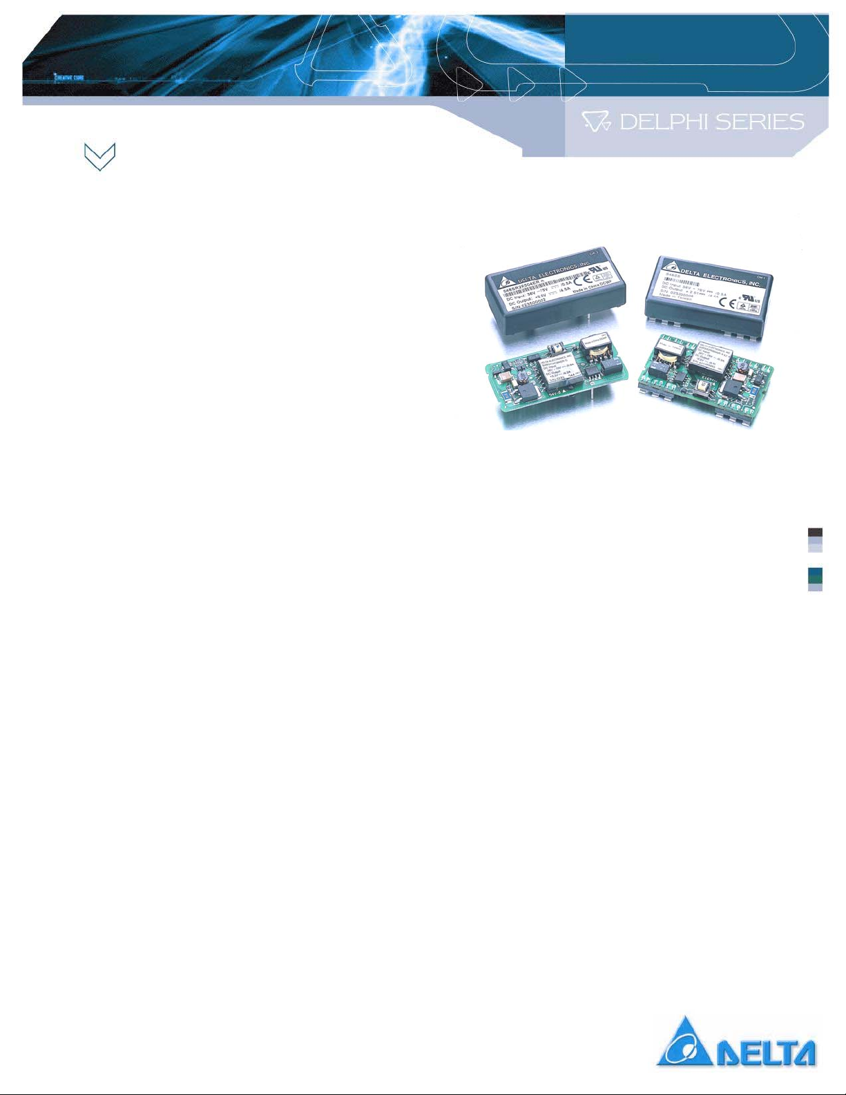
Delta Delphi Series 48Vin
S48SR and S48SS
The Delphi Series S48SR and S48SS,
48V input, single output, isolated DC/DC
converters are the latest offering from one
of the world’s largest power supply
manufacturers ― Delta Electronics, Inc.
With creative design technology and
optimization of component placement,
these converters possess outstanding
electrical and thermal performance, as well
as extremely high reliability under highly
stressful operating conditions. All models
are protected from abnormal input/output
voltage and current conditions. An
encapsulated version is available for the
most robust performance in harsh
environments.
This document guides the user through the
evaluation procedures to qualify a Delphi
module. The data shown in this Evaluation
Procedure is for the 3.3V unit. Please refe
to the appropriate technical data sheet fo
detailed performance and technical
information for Delphi units with differen
output voltages.
Delphi Series S48SR and S48SS
1.0 Purpose
This document guides the user to perform
electronic measurements on a Delphi
S48SR, 15W or a S48SS, 15W DC/DC
converter using the Delta Evaluation Board.
2.0 Relevant Documentation
The document and general knowledge listed
below is relevant to this evaluation
procedure:
2.1 S48SR or S48SS Series Applicable
Data Sheet
2.2 2”×1” Power Module Evaluation Board
Schematic
2.3 2”×1” Power Module Evaluation Board
Layout
2.4 General Test and Safety Procedures
2.5 ESD Protection
Evaluation Procedure
EP_SP
Version X1.0 November 2002
1
Delta Electronics, Inc.
Page 2

3.0 Equipment Required
3.1 (1) 0 ~ 80 V @ 0 ~10 A Power Supply (Chroma 6230K-80 or Equivalent)
3.2 (1) 4 Channel 150 MHz Oscilloscope, (1) 1× scope probe, (1) 10× scope probe
(Yokogama DL 1540C or Equivalent)
3.3 (1) 4 1/2 Digital Multimeter (DVM3) (HP34401A or Equivalent)
3.4 (2) 3 1/2 Digital Multimeter (DVM1 and DVM2) (FLUKE 45 or Equivalent)
3.5 (1) 300W Electronic or Resistive Load (Chroma 6304)
4.0 Equipment Set-Up and Description
4.1 Connect one wire from the “+” lead of the Power Supply (Item 3.1) to the “10A” of the
DVM1 (Item 3.4). Then connect one wire from the “Common” of the DVM1 to the
“Vin +” pin of the Evaluation Board.
4.2 Connect one wire from the “-” lead of the Power Supply to the “Vin -“ pin of the
Evaluation Board. Note: Use 10 AWG wire or similar for all connections in sections 4.1
and 4.2. Use twisted pair to reduce noise coupling.
4.3 Connect the plus “+” and minus “-“ connection wires from the multimeter (item 3.3) to
the “SVin +” and “SVin -” Pin on the Evaluation Board. The multimeter is designated
DVM2, above in Paragraph 3.0, Section 3.4.
4.4 Connect the plus “+” and minus “-“ connection wires from the multimeter (item 3.3) to
the “Sense +” and “Sense -” Pin on the Evaluation Board. The multimeter is designated
DVM3, above in Paragraph 3.0, Section 3.3.
4.5 Connect a BNC cable (length less than 20 inches) from BNC1 of the Evaluation Board
to Channel 1 of the oscilloscope (item 3.2).
4.6 Connect a BNC cable (length less than 20 inches) from BNC2 of the Evaluation Board
to Channel 2 of the oscilloscope (item 3.2).
4.7 Connect the Positive and Negative power leads of the Electronic load (assuring correct
polarity), or a resistive load to the Evaluation Board output terminal pin (“Vout +” for
positive power lead and “Vout -” for the negative power lead).
2
Page 3

5.0 Thermal of the Converter
It is imperative that sufficient airflow be provided to the converter at all times during all
portions of testing. Please refer to the applicable data sheet for the proper cooling and
derating necessary to achieve accurate results when testing the converter.
6.0 Tests Performed
The following tests are performed at room temperature +25 C.
6.1 Input Characteristics
Input Voltage Range
Under Voltage Lockout
No Load Input Current
Disable Input Current (applies to S48SS version only)
6.2 Output Characteristics
Line Regulation
Load Regulation
Output Regulation
Output Overvoltage Protection
6.3 Dynamic Characteristics
Maximum Output Voltage Deviation (due to step change in load)
Response time (due to step change in load)
Soft Start Turn-On Time
6.4 Thermal Characteristics
Efficiency
3
Page 4

7.0 Test Set-Up
7.1 Initial Set-Up
1) Examine the part number of the power module to determine of the unit is defined
for positive or negative logic enable as follows:
S48SS3R304NR would denote negative logic, while S48SS3R304PR would
denote positive logic (S48SS only).
2) If the power module has positive logic, switching SW1 to position HI or floating will
enable the power converter. Switching SW1 to position Low will disable the power
converter.
3) If the power module has negative logic, switching SW1 to position Low will enable
the power converter. Switching SW1 to position HI or floating will disable the power
converter.
4) Multimeters (1) Ampere / Autorange
Multimeters (2 and 3) Voltage / Autorange
5) Scope
Timebase 10 mS
Trigger Auto
Channel (1)
Volts / Div 10V
Coupling DC
Channel (2)
Volts / Div 1V
Coupling DC
6) Electronic Load
Turn on the Electronic Load and adjust the current level. The total output current is
4.5A (15W) for the S48SR power module and 4.5A (15W) for the S48SS power
module. Ensure the output load does not exceed the recommended maximum
current.
7) SW2 is used for trimming the output voltage. Turn SW2 to the OFF position if the
function is not being used. Turn SW2 to the UP position if trimming up is required.
Turn SW2 to the DOWN position if trimming down is required.
7.2 Initial Power Up
1) Turn the Power Supply on and increase the input voltage (use DVM2 to monitor the
voltage) until it reaches 48V (or the desired value).
2) Toggle SW1 to the appropriate logic position to turn the power module on (S48SS
only).
3) The converter is now operating, which can be verified by observing the DVM3
(approximately 3.3V.) and Channel 2 of the oscilloscope (+3.3V output).
4
Page 5

4) The converter may also be turned on by switching SW1 to the appropriate logic
enable position and ramping the voltage manually or turning on the Power Supply
with a preset output voltage (S48SS only).
5) Toggle SW1 to the “OFF” position after performing each test (S48SS only).
8.0 Test and Evaluation
8.1 Input Characteristic
8.1.1 Input Voltage Range
The Delphi S48SS3R304NR and S48SR3R304ER DC/DC converters will operate at
full load from 36Vin to 75Vin, steady state. The converter features input undervoltage protection which will not allow the converter to start up unless the input
voltage exceeds the turn-on voltage threshold.
Test
1) Turn on the fan.
2) Set the enable switch SW1 to the appropriate logic enable position (defined in
Section 7.1. S48SS only).
3) Set the input voltage to desired operating point while monitoring DVM2.
4) Test the input under voltage circuit while observing DVM2, DVM3 and Channel
1, Channel 2 of the oscilloscope. Increase the input voltage until the output of
the converter reaches stability (3.3 volts.) This will occur between 33.8 and 35.8
volts (please refer to the datasheet for the detailed specification).
8.1.2 No Load Input Current
Test
1) Turn on the fan.
2) Set the enable switch SW1 to the appropriate logic enable position (S48SS only).
3) Set the input voltage to desired operating point while monitoring DVM2.
4) Remove the electronic or the resistive load (output load)
5) Note the input current from DVM1.
6) The following is the result of the No load Input Current of the DC/DC converter.
The No Load Input Current will be around 25 mA (please refer to the datasheet for
the detailed specification).
5
Page 6

8.1.3 Input Current Module Off (S48SS only)
Test
1) Set the enable switch SW1 to the appropriate logic enable position to disable the
power supply (as defined in Section 7.1).
2) Adjust the input power supply to the desired operating point of interest while
monitoring DVM2.
3) Note the input current from DVM1.
4) This reading is the result of the Disable Input Current of the DC/DC converter.
The Disable Input current will be around 1 mA (please refer to the datasheet for the
detailed specification).
8.2 Output Characteristic
8.2.1 Line Regulation
Line Regulation is defined as the percentage change in output voltage caused by
varying the input voltage over the specified range (36 to 75 volts) while the output load
and temperature remain constant.
Test
1) Turn on the fan.
2) Set the enable switch SW1 to the appropriate logic enable position (S48SS only).
3) Set the output power to the desired operating point.
4) Adjust the input voltage across the converter’s input range (36 to 75 volts) while
monitoring DVM3.
5) Note the maximum +/- deviation of the output voltage over the full range of the
input operating voltage.
8.2.2 Load Regulation
Load Regulation is defined as the percentage change in output voltage caused by
varying the output load current over the specified range (no load to full load) while the
input voltage and temperature remain constant.
Test
1) Turn on the fan.
2) Set the enable switch SW1 to the appropriate logic enable position (S48SS only).
3) Set the input voltage to the desired operating point.
4) Adjust the output load across the converter’s operating load range (no load to full
load).
5) Note the maximum +/- deviation of the output voltage over the full range of the
operating load range.
6
Page 7

8.2.3 Output Ripple
Output Ripple is defined as the periodic AC component at the DC/DC converters
output voltage. The output ripple is measured in Peak to Peak and RMS values, both
done with a specific bandwidth.
Test
1) Turn on the fan.
2) Set the enable switch SW1 to the appropriate logic enable position.
3) Adjust the input voltage and output load to the desired operating point (S48SS
only).
4) Adjust Channel 2 on the oscilloscope to be AC coupled @ 2uS / Div and 50mV/Div
to use the 20 MHz bandwidth of the scope.
5) The output ripple of the DC/DC converter is measured at full load operating power.
8.3 Dynamic Characteristics
8.3.1 Output Voltage Deviation
Output Voltage Deviation is defined as the response of the converter to a sudden step
change in the output load current. The output voltage deviation is characterized by two
important parameters: Maximum Output Voltage Deviation and Response Time, which
is the length of time that the output voltage takes to return to 1% of its specified value
(please refer to the datasheet for the detailed specification).
Test -S48SS & S48SR
1) Turn on the fan.
2) Set the enable switch SW1 to the appropriate logic enable position (S48SS only).
3) Adjust the input voltage to the desired operating point.
4) Set Channel 2 on the oscilloscope to be AC coupled and to 50mV/Div and
5mS/Div. Set the trigger to auto and adjust the trigger point for a negative going
pulse.
5) Set the Electronic Load in dynamic mode and set it for the desired load transient.
6) Measure the positive Peak or negative Peak deviation and response time of the
output voltage during the load transient.
7
Page 8

8.3.2 Soft Start Turn-On Time
Soft Start Turn-On Time is defined as the time it takes for the output to rise to within
95% of its final value from the time when the converter is enabled. The rise time is
deliberately made slower to reduce the inrush current and to eliminate any overshoot
in the output voltage.
Test -S48SR & S48SS ( turn on the module by using the input power supply)
1) Turn on the fan.
2) Set the enable switch SW1 to the appropriate logic enable position (S48SS only).
3) Turn on the input Power Supply and set it to the desired operating point.
4) Set the input Power Supply disable by an external switch or use the input Power
Supply internal disable function.
5) Set Channel 1 on the oscilloscope to be DC coupled and to 1V/Div.
6) Connect a coaxial cable from Channel 1 to BNC2 on the Evaluation Board.
7) Set Channel 2 on the oscilloscope to be DC coupled and to 20V/Div.
8) Connect a coaxial cable from Channel 2 to BNC1 on the Evaluation Board.
9) Set the Timebase to 10 mS/Div.
10) Set the Trigger for a one time event and set the Trigger level at approximately 2V
on Channel 1.
11) Enable the input Power Supply to supply power and record the waveforms on the
oscilloscope.
Test-S48SS (turn on the module by using the Remote on/off feature)
1) Turn on the fan.
2) Set the enable switch SW1 to the appropriate logic disable position.
3) Turn on the input Power Supply and set the input voltage to the desired operating
point.
4) Set Channel 1 on the oscilloscope to be DC coupled and to 1V/Div.
5) Connect a coaxial cable from Channel 1 to BNC2 on the Evaluation Board.
6) Set Channel 2 on the oscilloscope to be DC coupled and to 2V/Div.
7) Set the Timebase to 10 mS/Div.
8) Set the Trigger for a one time event and set the Trigger level to approximately 2V
on Channel 2.
9) Connect the 10X probe (Channel 2) to the “ON/OFF” test point on the evaluation
board and connect the ground clip to the “Vin –“ pin on the evaluation board.
10) Set the enable switch SW1 to the appropriate logic position to enable power and
record the waveforms on the oscilloscope.
8
Page 9

Note: Different electronic loads may have dramatically different results because of
their input characteristics during Turn-On. If the Turn-On appears abnormal, replace
with an actual resistive load of appropriate value.
The Soft Start Turn-On Time of the converter provided in the Evaluation Kit was
measured with the Electronic Load set at 4.5A.
8.4 Thermal Characteristics
8.4.1 Efficiency
Efficiency is the ratio of total output power to the input power. It is typically measured
at full load and nominal input voltage.
Test
1) Turn on the fan.
2) Set the enable switch SW1 to the appropriate logic enable position (S48SS only).
3) Adjust the input voltage to the desired operation point.
4) Set the Electronic Load to the desired operating point..
5) Read and note the +3.3 output voltage (DVM3) and input voltage (DVM2).
6) Read and note the input and output currents from the DVM1 and the Electronic
Load.
9
Page 10
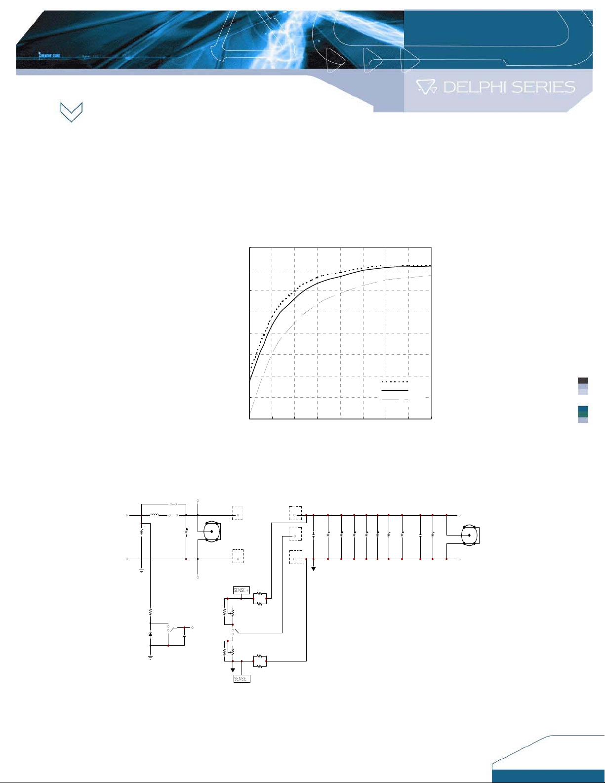
7) Use the following formulas to calculate the efficiency:
Efficiency= (Pout/Pin) × 100(%)
Pin = Iin × Vin
Pout = Iout × Vout
The following graph shows the efficiency results of the S48SS/S48SR
converters measured at different operating points.
90
85
EFFICIENCY (%)
80
75
70
65
60
55
50
0.5 1 1.5 2 2.5 3 3.5 4 4.5
Appendix A- Evaluation Board Schematic
L1
VIN+
NC BNC1
C2
NC
VIN-
R1
NC
NC
ZD1NC
Low
Hi
COPPER
SW1
1
3
Floating
2
NC C1
C3
68u/100V
ON/OFF
SVin+
SVin-
VIN+
VIN-
J2
J3
R3
NC
SW2
R2
NC
0
VR1
100K
DOWN
3
OFF
2
1
UP
J1
VR2
100K
J4
0
VOUT+
TRIM
C101NCC102NCC104
VOUT-
NC
NC
OUTPUT CURRENT (A)
C103NCC107NCC108
NC
C109NCC110NCC105
NC
36Vin
48Vin
75Vin
1u/25V
C106
10u/25V
VOUT+
BNC2
VOUT-
10
Page 11
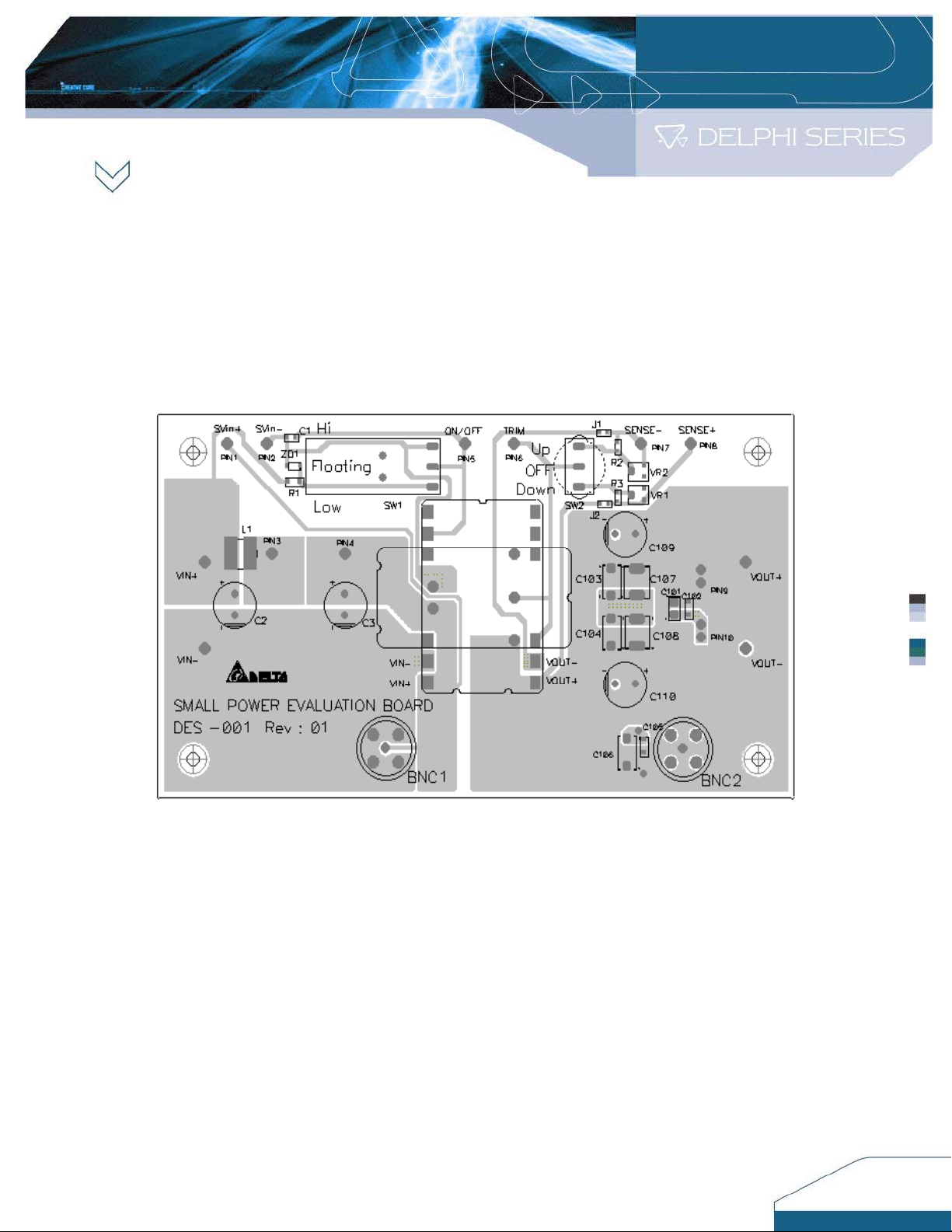
Appendix B - Evaluation Board Layout (Top View)
11
Page 12
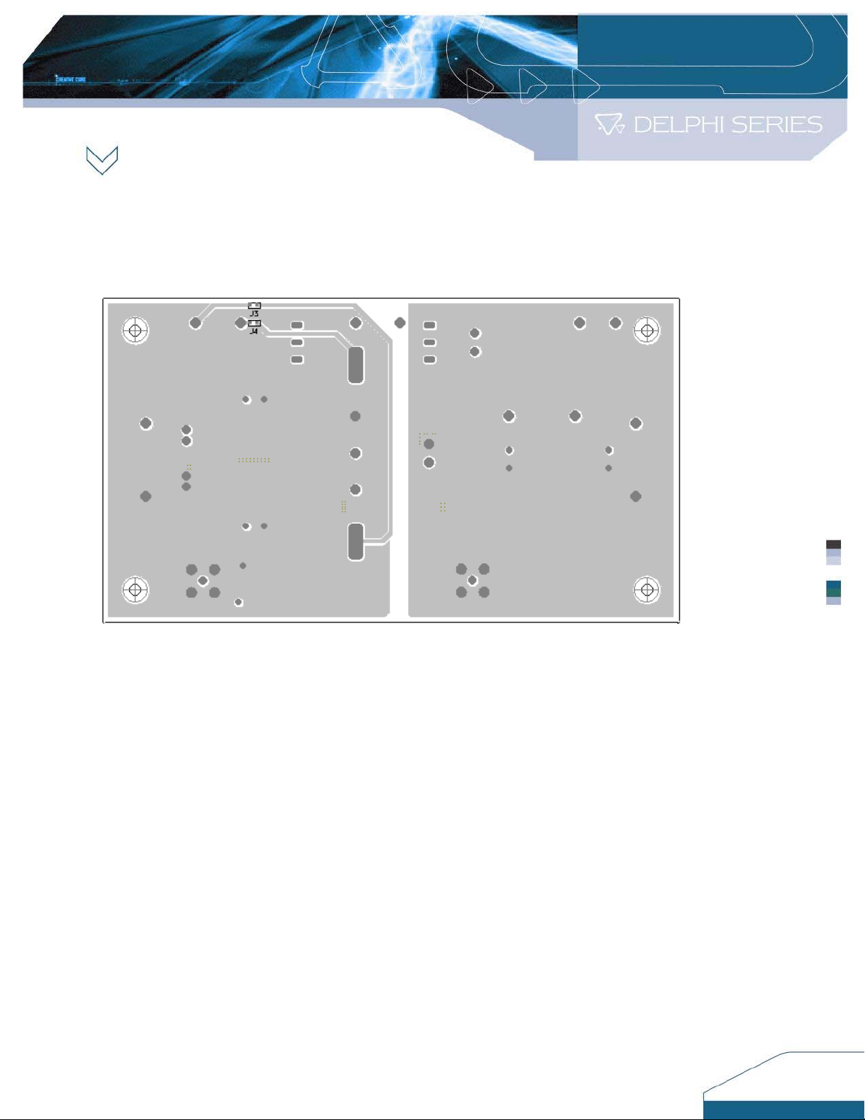
Appendix C- Evaluation Board Layout (Bottom View)
CONTACT DATA:
USA:
Telephone:
East Coast: (888) 335 8201
West Coast: (888) 335 8208
Fax: (978) 656 3964
Email: DCDC@delta-corp.com
www.deltaww.com
Europe:
Telephone:
France: +33 1 6485 1212
Germany: +49 89 370 62 897
UK: +44 777 195 6299
Fax: +33 1 6485 1212
Email: DCDC@euro.delta-corp.com
Asia:
Telephone: +886 3 4526107 x6202
Fax: +886 3 4331707
Email: DCDC@delta.com.tw
Warranty
Delta offers a two (2) year limited warranty. Complete warranty information is listed on our web site or is
available upon request from Delta.
Information furnished by Delta is believed to be accurate and reliable. However, no responsibility is assumed by
Delta for its use, nor for any infringements of patents or other rights of third parties, which may result from its
use. No license is granted by implication or otherwise under any patent or patent rights of Delta. Delta reserves
the right to revise these specifications at any time, without notice.
12
 Loading...