

Page 1

RTU-DNET
DeviceNet Remote I/O Communication
Module
Application Manual
Page 2

Page 3

DeviceNet Remote I/O Communication Module R TU-DNET
Warning
3
Please read this instruction carefully before use and follow this instruction to operate the device in order to prevent
damages on the device or injuries to staff.
3
Switch off the power before wiring.
3
RTU-DNET is an OPEN TYPE device and therefore should be installed in an enclosure free of airborne dust,
humidity, electric shock and vibration. The enclosure should prevent non-maintenance staff from operating the
device (e.g. key or specific tools are required for operating the enclosure) in case danger and damage on the
device may occur.
3
RTU-DNET is to be used for controlling the operating machine and equipment. In order not to damage it, only
qualified professional staff familiar with the structure and operation of RTU-DNET can install, operate, wire and
maintain it.
3
DO NOT connect input AC power supply to any of the I/O terminals; otherwise serious damage may occur. Check
all the wirings again before switching on the power and DO NOT touch any terminal when the power is switched
on. Make sure the ground terminal
1 INTRODUCTION ....................................................................................................................................3
2 PRODUCT PROFILE & OUTLINE .........................................................................................................5
Table of Contents
1.1 Features......................................................................................................................................3
1.2 Functions.....................................................................................................................................3
1.3 Specifications..............................................................................................................................3
1.4 Extension Modules Connectable to RTU-DNET .........................................................................4
2.1 Dimension ...................................................................................................................................5
2.2 Product Profiles...........................................................................................................................5
2.3 DeviceNet Connection Port.........................................................................................................6
2.4 RUN/STOP Switch......................................................................................................................6
is correctly grounded in order to prevent electromagnetic interference.
2.5 Address Switch ...........................................................................................................................6
2.6 Function Switch...........................................................................................................................6
2.7 Extension Port.............................................................................................................................7
3 BASIC OPERATION...............................................................................................................................7
3.1 Connecting RTU-DNET to DVP Slim DI/DO Extension Unit....................................................... 7
3.2 Installing RTU-DNET and DVP Slim DI/DO on DIN Rail.............................................................7
3.3 Connecting to DeviceNet Connection Port..................................................................................8
4 HOW TO CONFIGURE RTU-DNET .......................................................................................................8
4.1 Terms ..........................................................................................................................................8
4.2 Format of Requet Message and Response Message.................................................................9
DVP-PLC Application Manual
1
Page 4

DeviceNet Remote I/O Communication Module R TU-DNET
4.3 DeviceNet I/O Mapping Data.................................................................................................... 14
4.4 Example.................................................................................................................................... 17
5 HOW TO CONSTRUCT A DEVICENET NETWORK USING RTU-DNET...........................................22
5.1 How to Construct DeviceNet by RTU-DNET ............................................................................22
5.2 How to Configure Network by DeviceNet Network Configuration Tool..................................... 22
6 LED INDICATOR & TROUBLE-SHOOTING ....................................................................................... 31
6.1 POWER LED............................................................................................................................31
6.2 NS LED..................................................................................................................................... 31
6.3 MS LED.................................................................................................................................... 31
6.4 ALARM LED............................................................................................................................. 31
6.5 RUN LED.................................................................................................................................. 32
2
DVP-PLC Application Manual
Page 5

DeviceNet Remote I/O Communication Module R TU-DNET
A
1 Introduction
1. To ensure correct installation and operation of RTU-DNET, please read this chapter carefully before using
your RTU-DNET.
2. This chapter only provides introductory information on RTU-DNET. For more detailed information on
DeviceNet protocol, please refer to relevant references or literatures.
3. RTU-DNET is a remote I/O communication module applicable to the connectio n between DeviceNet an d DVP
Slim DIDO module and special modules. RTU-DNET offers functions such as status diagnosis, error
treatment and so on.
1.1 Features
z Supports Group 2 only servers.
z Supports explicit connection via predefined Master/Slave connection set.
z Supports polling
z Supports EDS file configuration in DeviceNet network configuration tools.
z Max. 256 digital I/O points extendable.
z Max. 8 special modules extendable.
1.2 Functions
Item Explanation
Graphic configuration
interface
Data retention
uto extension module
identification
Diagnosis
Status inquiry
Error inquiry The user can read the error through DeviceNet network configuration tool.
Error treatment
Flexible configuration
RTU-DNET supports gra phic configuration interface in DeviceNet network
configuration tools.
The user can choose either to retain or give up the data in the register when
RTU-DNET is offline.
The user can automatically identify the special module or the enumber of points on
the DVP Slim DI/DO extension unit connected to RTU-DNET through DeviceNet
network configuration tool.
RTU-DNET is able to diagnose the status of the special module connected to it.
When an error occurs, The ALARM LED on RTU-DNET will flash in red.
RTU-DNET is able to inquire the connection status bet ween itself and the extension
module in DeviceNet network configuration tool.
The user can choose a method to correct the error through DeviceNet network
configuration tool.
The user can configure the control register (CR) in the special module in any way as
the I/O mapping data for DeviceNet.
1.3 Specifications
DeviceNet connection
Transmission method CAN
Electrical isolation 500 VDC
Interface Removable connector (5.08mm)
Transmission cable 2-wire twister shielded cable with 2-wire bus power and drain
Communication
Message type I/O polling, explicit
DVP-PLC Application Manual
3
Page 6
DeviceNet Remote I/O Communication Module R TU-DNET
Baud rates 125 kbps; 250 kbps; 500 kbps
Electrical specification
Voltage 11 ~ 25 VDC, supplied by internal bus from PLC MPU
Current 28mA (typical), 125mA impulse current (24 VDC)
Environment
ESD (IEC 61131-2, IEC 61000-4-2): 8KV Air Discharge
EFT (IEC 61131-2, IEC 61000-4-4): Power Line: 2KV, Digital I/O: 1KV
Noise immunity
Operation 0ºC ~ 55ºC (temperature); 50 ~ 95% (humidity); pollution degree 2
Storage -25ºC ~ 70ºC (temperature); 5 ~ 95% (humidity)
Analog & Communication I/O: 1KV
Damped-Oscillatory Wav e: Power Line: 1KV, Digital I/O: 1KV
RS (IEC 61131-2, IEC 61000-4-3): 26MHz ~ 1GHz, 10V/m
Vibration/shock
resistance
Standard: IEC 61131-2, IEC 68-2-6 (TEST Fc)/IEC 61131-2 & IEC 68-2-27 (TEST
Ea)
Certificates IEC 61131-2, UL508
1.4 Extension Modules Connectable to RTU-DNET
T
E
N
D
U
T
R
T
S
8
0
P
V
D
DVP Slim DI/DO extension units connectable to RTU-DNET
Slim DI/DO
(model name)
(DeviceNet → RTU-DNET)
DVP-08SM11N N/A 8 bits
P
S
6
1
P
V
D
I/O mapping data
D
A
4
0
P
V
D
C
T
4
0
P
V
D
T
P
4
0
P
V
D
A
D
2
0
P
V
D
I/O mapping data
(RTU-DNET → DeviceNet)
DVP-08SN11R/T 8 bits N/A
DVP-08SP11R/T 8 bits 8 bits
DVP-16SP11R/T 8 bits 8 bits
DVP-08ST N/A 8 bits
Special modules connectable to RTU-DNET
Default I/O mapping data
Special module
(DeviceNet → RTU-DNET)
(model name)
Start CR Length (words) Start CR Length (words)
DVP-02DA CR#10 2 N/A N/A
DVP-04DA CR#6 4 N/A N/A
DVP-04AD N/A N/A CR#12 4
DVP-06AD N/A N/A CR#12 6
4
I/O mapping data
(RTU-DNET → DeviceNet)
DVP-PLC Application Manual
Page 7
DeviceNet Remote I/O Communication Module R TU-DNET
Special module
Default I/O mapping data
(DeviceNet → RTU-DNET)
I/O mapping data
(RTU-DNET → DeviceNet)
(model name)
Start CR Length (words) Start CR Length (words)
DVP-04TC N/A N/A CR#14 4
DVP-04PT N/A N/A CR#18 4
DVP-06XA CR#10 2 CR#12 4
DVP-01PU CR#42 4 CR#33 4
Note:
While connected to a special module, the start CR and length of upload/download data of RTU-DNET can be set
up in DeviceNet network configuration tool.
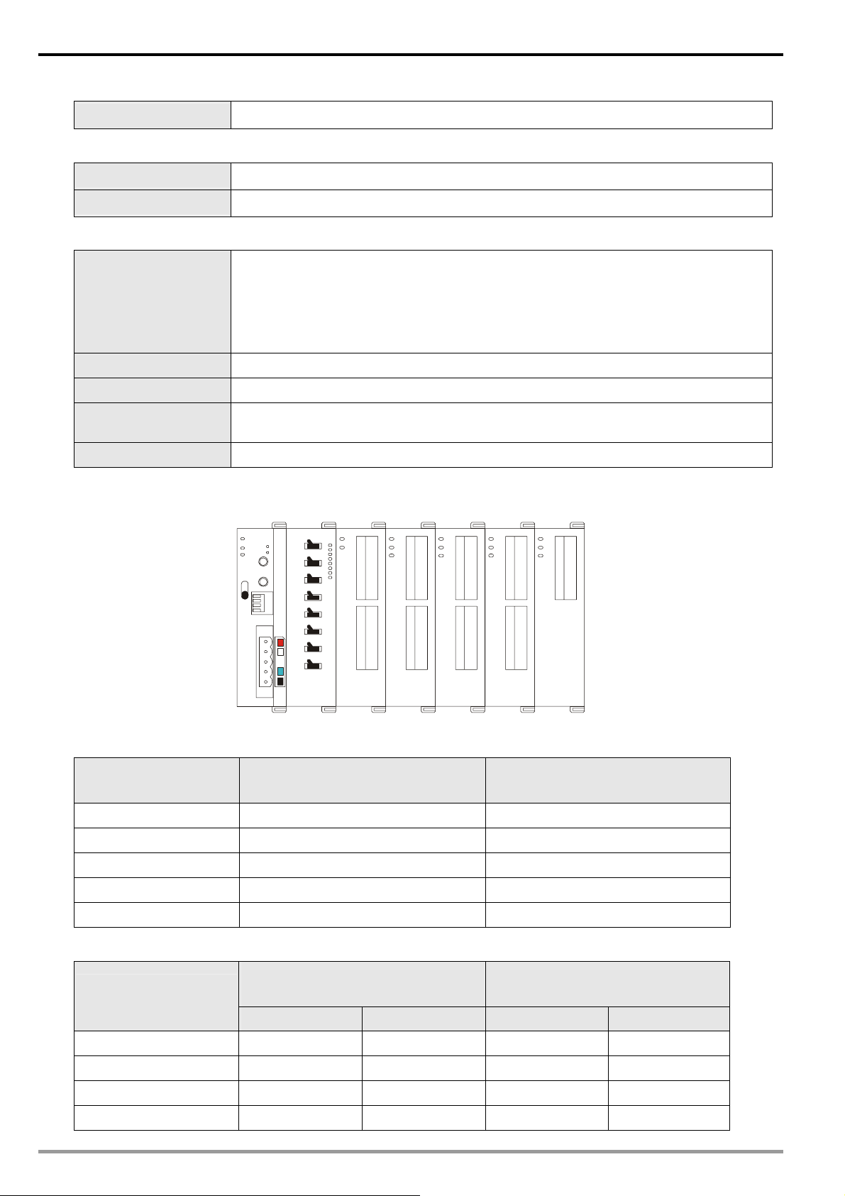
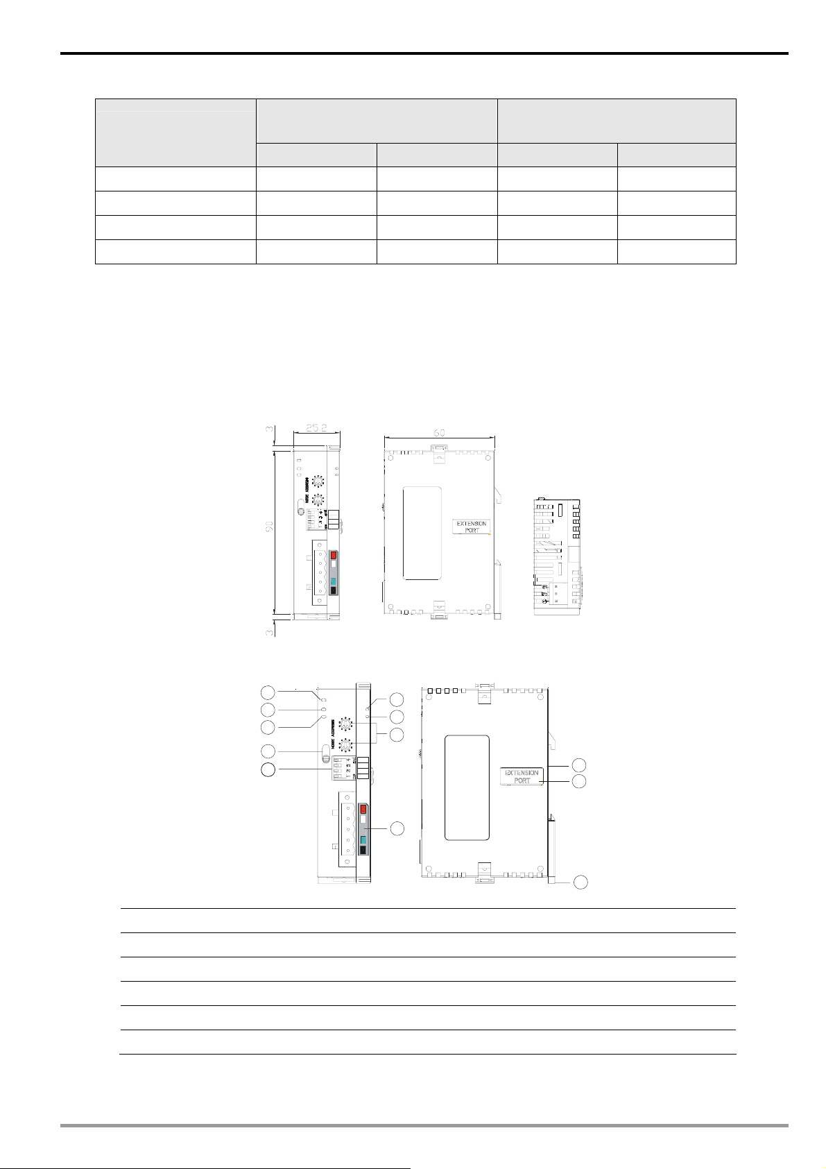
2 Product Profile & Outline
2.1 Dimension
POWER
MS
RUN
5
6
NS
4
ALARM
7
3
1
8
2
x10
9
1
0
5
6
4
RUN
7
3
0
8
2
x10
9
1
0
DR 1
DR 0
STOP
IN 1
IN 0
2.2 Product Profiles
1. Extension port 7. NS (Network Status) indicator
2. Address switch 8. RUN indicator
3. Function switch 9. ALARM indicator
RTU-DNET
5
6
7
4
3
POWER
MS
5
6
NS
4
3
2
9
1
0
5
6
4
RUN
3
2
9
1
0
STOP
RTU-DNET
8
RUN
ALARM
7
9
1
8
x10
2
7
0
8
x10
DR 1
DR 0
IN 1
IN 0
11
1
10
12
4. RUN/STOP switch 10. DeviceNet connection port
5. POWER indicator 11. DIN rail
6. MS (Module Status) indicator 12. DIN rail clip
DVP-PLC Application Manual
5
Page 8
DeviceNet Remote I/O Communication Module R TU-DNET
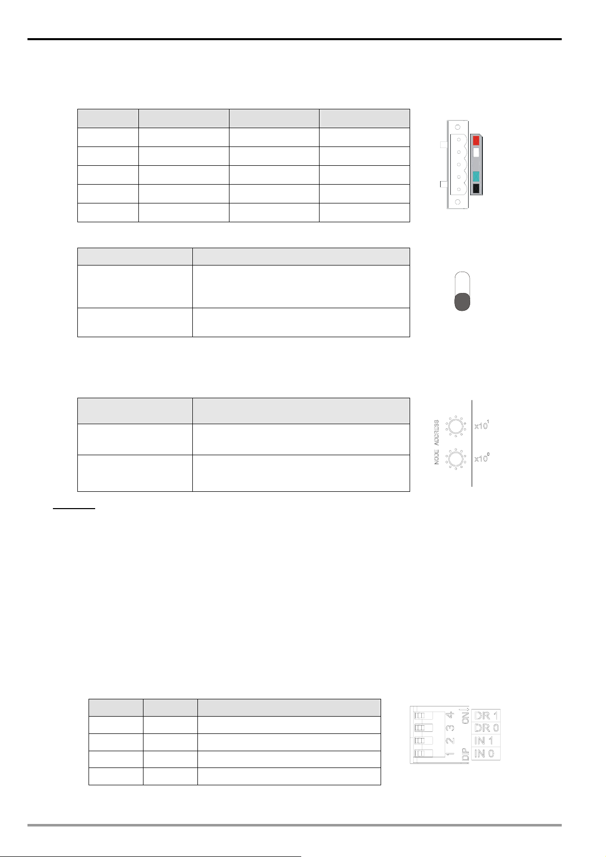
2.3 DeviceNet Connection Port
The connector is used on the connection to DeviceNet. Wire by using the connector enclosed with RTU-DNET.
PIN Signal Color Content
1 V- Black 0 VDC
2 CAN_L Blue Signal-
5
4
3
3 SHIELD - Shielded
4 CAN_H White Signal+
5 V+ Red 24 VDC
2
1
2.4 RUN/STOP Switch
RUN/STOP action Explanation
1. Re-detecting the extension module.
STOP → RUN
2. Reading/writing the data in the extension
module.
RUN → STOP
Stop reading/ writing the data in the extension
module.
RUN
STOP
2.5 Address Switch
The switch is used on setting up the node address of RTU-DNET on DeviceNet. Range: 00 ~ 63 (64 ~ 99 are
forbidden).
Switch setting Content
0 ~ 63 Valid DeviceNet node address
64 ~ 99 Invalid DeviceNet node address
5
6
4
7
3
8
2
9
1
0
5
6
4
7
3
8
2
9
1
0
Example: If you need to set the node address of RTU-DNET to 26, simply switch the corresponding swit ch of x101
to 2 and the corresponding switch of x10
0
to 6.
Note:
z Please set up the node address when the power is switched off. After the setup is completed, re-power
RTU-DNET.
z When RTU-DNET is operating, changing the setting of node address will be invalid.
z Use slotted screwdriver to rotate the switch carefully in case you scratch the switch.
2.6 Function Switch
The function switches are for:
z Setting up data retention function (IN0)
z Setting up the baud rate of DeviceNet (DR0 ~ DR1)
DR1 DR0 Baud rate
OFF OFF 125 kbps
OFF ON 250 kbps
ON OFF 500 kbps
ON ON Incorrect setting
6
DVP-PLC Application Manual
Page 9
DeviceNet Remote I/O Communication Module R TU-DNET
OFF
When DeviceNet is off, the I/O data in
the buffer area will be cleared.
IN0
ON
When DeviceNet is off, the I/O data in
the buffer area will be held.
IN1 Reserved
Note:
z Please set up the function switch when the power is switched off. After the setup is completed, re-power
RTU-DNET.
z When RTU-DNET is operating, changing the setting of the function switch will be invalid.
z Use slotted screwdriver to adjust the DIP switch carefully in case you scratch the switch.
2.7 Extension Port
The extension port is used on connecting RTU-DNET to DVP Slim DI/DO extension units and special modules.
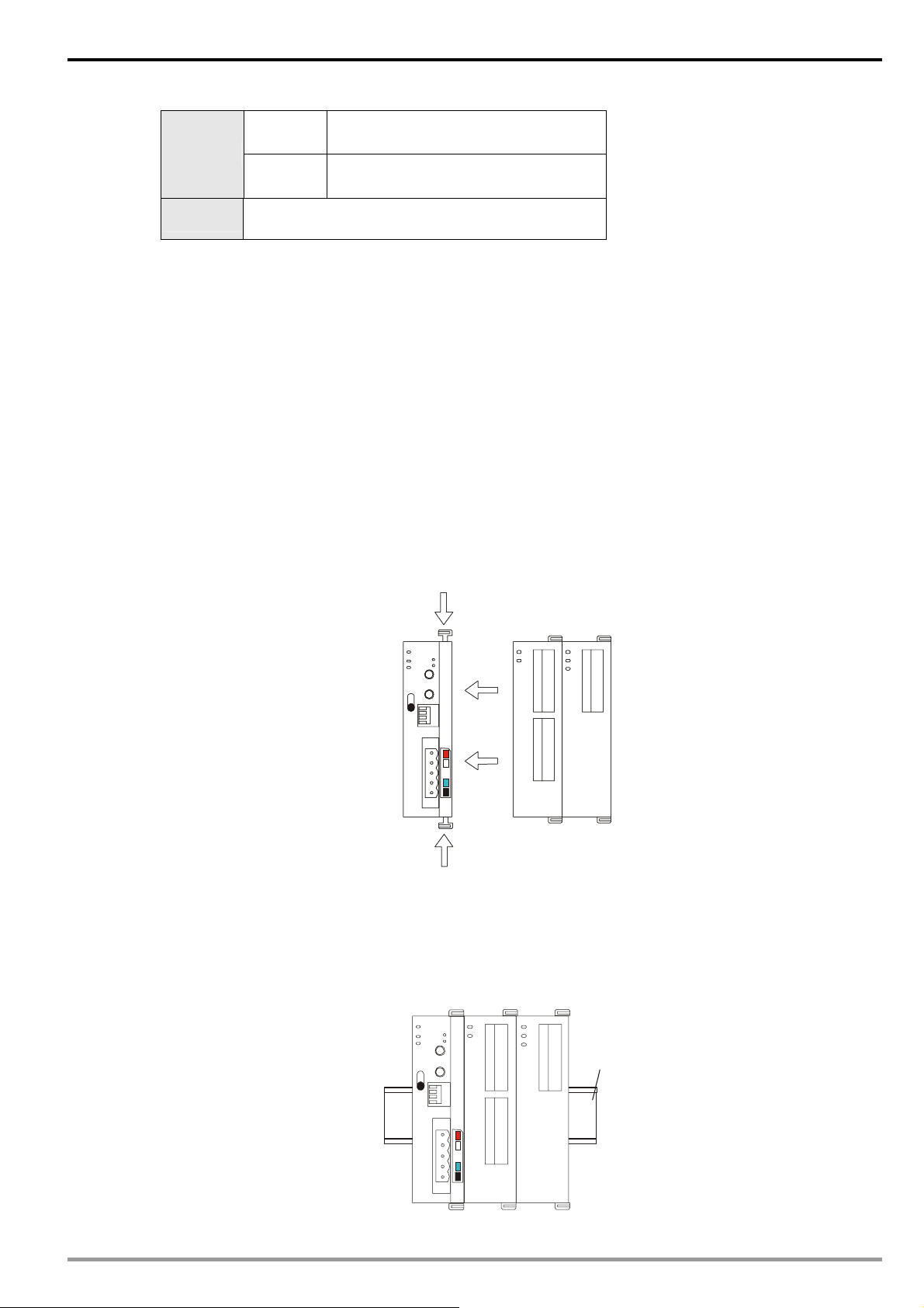
3 Basic Operation
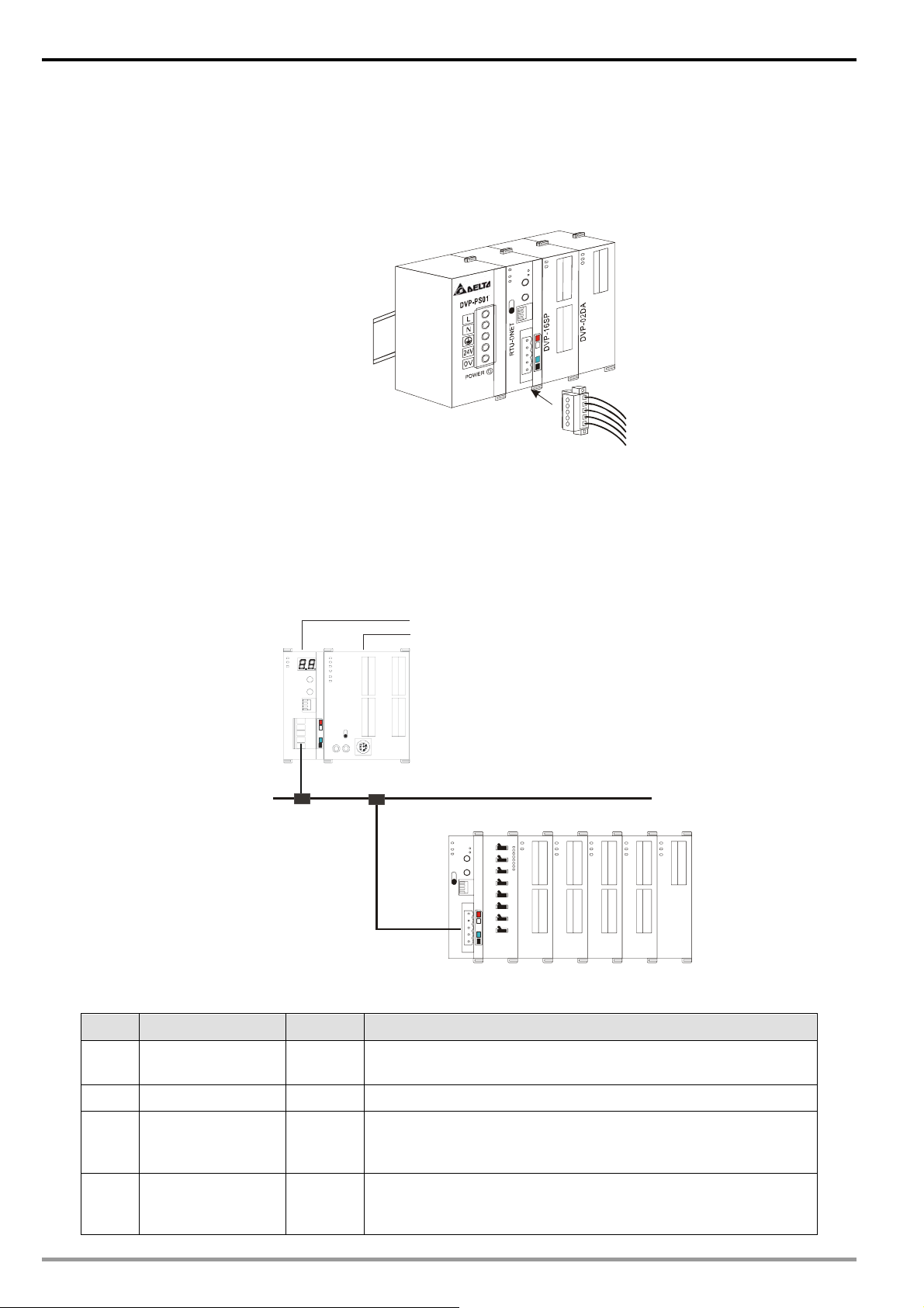
3.1 Connecting RTU-DNET to DVP Slim DI/DO Extension Unit
z Open the fixing clips on top and bottom of RTU-DNET. Meet the extension port of Slim DI/DO with RTU-DNE T.
z Press the fixing clips on top and bottm of Slim DI/DO and check if the connection is fine.
T
T
E
E
N
N
D
D
-
U
U
T
T
R
R
P
P
S
S
6
6
1
1
-
P
P
V
V
D
D
A
A
D
D
2
2
0
0
-
P
P
V
V
D
D
3.2 Installing RTU-DNET and DVP Slim DI/DO on DIN Rail
z Use 35mm DIN rail.
z Open the DIN rail clip on RTU-DNET and Slim DI/DO. Insert RTU-DNET and Slim DI/DO onto the DIN rail.
z Clip up the DIN rail clips on RTU-DNET and Slim DI/DO to fix them on the DIN rail, as shown below .
35mm DIN rail
T
E
N
D
U
T
R
P
S
6
1
P
V
D
A
D
2
0
P
V
D
DVP-PLC Application Manual
7
Page 10
DeviceNet Remote I/O Communication Module R TU-DNET
3.3 Connecting to DeviceNet Connection Port
z The colors on the PINs on the DeviceNet connection port match the colors of the connection cables. Make
sure you connect the cable to the right PIN.
z We recommend you also apply Delta’s power module in the connection.
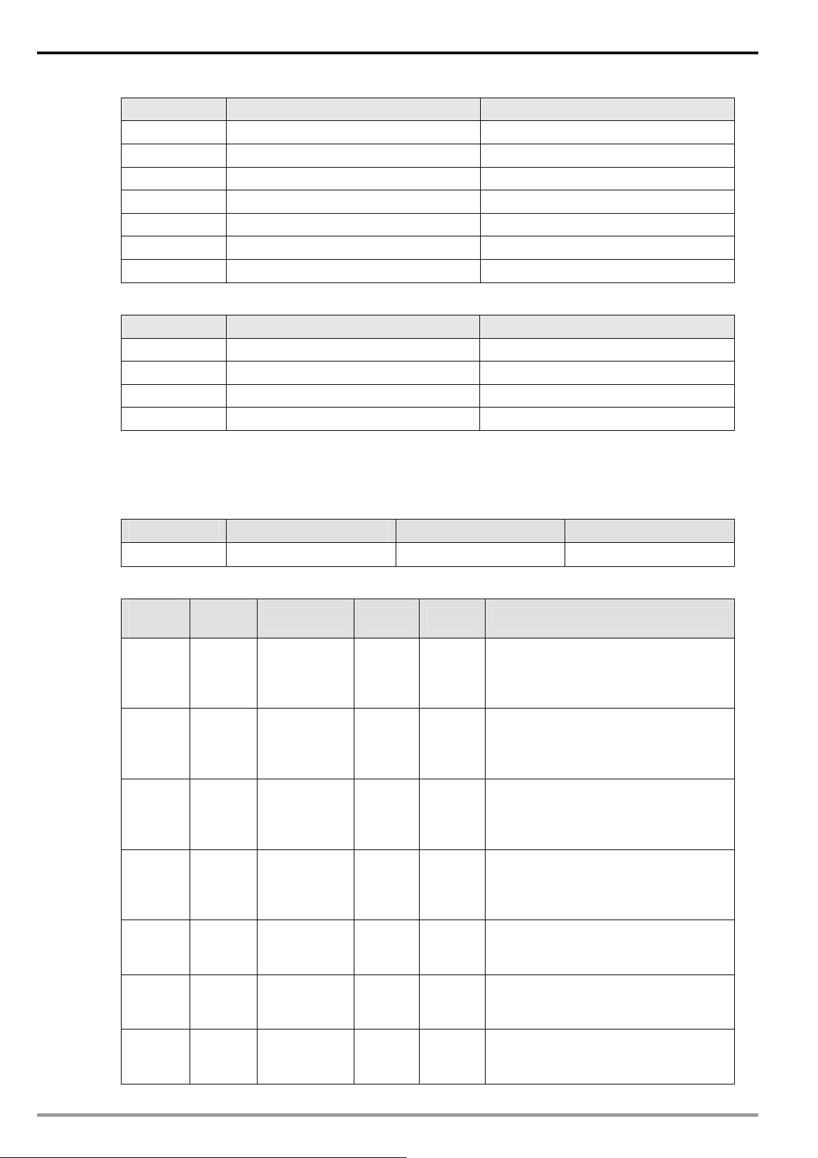
4 How to Configure RTU-DNET
In this section we will introduce how RTU-DNET as a DeviceNet slave realizes the data exchange between
DeviceNet master and DVP Slim DI/DO extension unit.
z DeviceNet master sends the data to Slim DI/DO.
z RTU-DENT sends the input data from Slim DI/DO to DeviceNet master.
DVPDNET-SL
DVP28SV
DVPDNET DVP28SV
RUN
STOP
Master
T
T
E
N
D
U
T
R
P
S
S
8
6
0
1
-
-
P
P
V
V
D
D
C
D
T
A
4
4
0
0
-
P
P
V
V
D
D
A
T
D
P
2
4
0
0
-
P
P
V
V
D
D
DeviceN et
4.1 Terms
No. Item Unit Explanation
1 Control word Word
2 Status word Word Displaying the status of RTU-DNET. See 4.3 for more details.
3
4
8
Number of digital
input points
Number of digital
output points
Bit
Bit
For setting up the mode of RTU-DNET, e.g. “H8000” for STOP
mode and “H8001” for RUN mode. See 4.3 for more details.
The digital input points shall be 8’s multiple. The number will be
regarded as 8 when it is less than 8 and as 16 when it is bigger
than 8 but less than 16.
The digital output points shall be 8’s multiple. The num ber will be
regarded as 8 when it is less than 8 and as 16 when it is bigger
than 8 but less than 16.
DVP-PLC Application Manual
Page 11

DeviceNet Remote I/O Communication Module R TU-DNET
No. Item Unit Explanation
Length of input data
5
6
7
8
9
10
11
12
of special module
Length of output
data of special
module
Length of input I/O
Length of output I/O
Number of special
modules
Diagnostic interval
Special module
offline treatment
Special module erro
treatment
data
data
time
Word
Word
Byte
Byte
Unit
Sec
N/A
N/A
The length of input data of the special module connected to
RTU-DNET
The length of output data of the special module connected to
RTU-DNET
The sum of the length of the status word of RTU-DNET and the
input data of the special module connected to it. One input
channel of the special module occupies 2 bytes. 8 points of the
digital input are counted as 1 byte.
The sum of the length of the control word of RTU-DNET and
theoutput data of the special module connected to it. One output
channel of the special module occupies 2 bytes. 8 points of the
digital output are counted as 1 byte.
The number of special modules connected to RTU-DNET.
Range: 0 ~ 8
The interval when RTU-DNET executes diagnosis.
Range: 1 ~ 65, Default: 5 secs
How RTU-DNET will react when the special module connected
to it is offline. You can choose “Ignored”, “Alarm” or “Stop
DeviceNet IO”. Default: Alarm
How RTU-DNET will react when it detacts errors. You can
choose “Ignored”, “Alarm” or “S top DeviceNet IO”. Default:
Alarm
13 Reset RTU-DNET N/A Reset the configuration of RTU-DNET to default settings.
For you to decide whether to add control word and status word
Add control word
14
15 Work mode N/A
16
17
18 Length of input data Word
19
20 I/O mapping N/A
and status word to
I/O data
Number of input
data connected
Number of output
data connected
Length of output
data
N/A
---
---
Word
to I/O data. When you choose not to do it, the I/O data in
RTU-DNET and DeviceNet master will not include control word
and status word. If you choose to add them in, the I/O data in
RTU-DNET and DeviceNet master will include control word and
status word.
For you to set up the work mode of the special module
connected to RTU-DNET. When set to “auto mode”, RTU-DNET
will configure default CR of the special module as DeviceNet I/O
mapping data. When set to “custom mode”, you can configure
any CR in the special module as DeviceNet I/O mapping data.
The number of input data of the special module connected to
RTU-DNET
The number of output data of the special module connected to
RTU-DNET
The sum of the length of input data of the special modules
connected to RTU-DNET
The sum of the length of output data of the special modules
connected to RTU-DNET
The I/O mapping relation between RTU-DNET and the special
module connected to it
4.2 Format of Requet Message and Response Message
1. RTU-DNET supports using DeviceNet explicit messages to poll special modules.
Format of request messages
Byte position Data written into special module Data read from special module
0 Frag[0]+XID+MAC ID Frag[0]+XID+MAC ID
DVP-PLC Application Manual
9
Page 12
DeviceNet Remote I/O Communication Module R TU-DNET
Byte position Data written into special module Data read from special module
1 R/R[0]+Service Code[0x10] R/R[0]+Service Code[0x0E]
2 Class ID [0x9C] Class ID [0x9C]
3 Instance ID Instance ID
4 Attribute ID Attribute ID
5 Low byte of Service Data N/A
6 High byte of Service Data N/A
7 N/A N/A
Format of response messages
Byte position Data written into special module Data read from special module
0 Frag[0]+XID+MAC ID Frag[0]+XID+MAC ID
1 R/R[1]+Service Code[0x10] R/R[1]+Service Code[0x0E]
2 Low byte of response data
3 High byte of response data
2. Definitions of DeviceNet Objects for RTU-DNET
Class 0x9A – RTU-DNET setup parameter object
Class attribute
Attribute ID Access rule Name Data type
1 Get Revision UINT
Instance 1
Attribute
ID
1 Get
2 Get
3 Get
4 Get
5 Get
6 Get
7 Get
Access
rule
Name Range Default Explanation
Length of
input I/O data
Length of
output I/O
data
Number of
digital input
points (X)
Number of
digital output
points (Y)
Number of
special
modules
Length of
analog input
Length of
analog output
N/A N/A
N/A N/A
0 ~ 128 N/A
0 ~ 128 N/A
0 ~ 8 N/A
N/A N/A
N/A N/A
The sum of the length of the status
word of RTU-DNET and the input data
of the module connected to it. (Unit:
byte)
The sum of the length of the control
word of RTU-DNET and the output
data of the module connected to it.
(Unit: byte)
The number will be regarded as 8
when it is less than 8 and as 16 when it
is bigger than 8 but less than 16. (Unit:
bit)
The number will be regarded as 8
when it is less than 8 and as 16 when it
is bigger than 8 but less than 16. (Unit:
bit)
The number of special modules
connected to RTU-DNET .
The length of input data of the special
module connected to RTU-DNET.
(Unit: word)
The length of output data of the special
module connected to RTU-DNET.
(Unit: word)
10
DVP-PLC Application Manual
Page 13

DeviceNet Remote I/O Communication Module R TU-DNET
Attribute
ID
8 Get Status word 0~255 N/A
9 Get/Set Control word N/A N/A
10 Get/Set
11 Get/Set
12 Get/Set
13 Get/Set
14 Get/Set
Access
rule
Name Range Default Explanation
Diagnostic
interval time
Special
module offline
treatment
Special
module error
treatment
RTU-DNET
configuration
validation
Reset
RTU-DNET
1 ~ 65
secs
0 ~ 2 1
0 ~ 2 1
N/A 0
N/A 0
5 secs
Displaying the status of RTU-DNET.
See 4.3 for more details.
For setting up the mode of RTU-DNET,
e.g. “H8000” for STOP mode and
“H8001” for RUN mode. See 4.3 for
more details.
The interval when RTU-DNET
executes diagnosis.
How RTU-DNET will react when the
special module connected to it is
offline.
0: Ignored
1: Alarm
2: Stop DeviceNet IO
How RTU-DNET will react when it
detects errors.
0: Ignored
1: Alarm
2: Stop DeviceNet IO
Validating the configuration of
RTU-DNET when set to “11”.
Resetting RTU-DNET when set to”10”.
After it, the parameter will change to
“0” automatically.
Class 0x9B – Extension module setup parameter object
Class attribute
Attribute ID Access rule Name Data type
1 Get Revision UINT
Instance 1 ~ 8 (parameters for the 1st ~ 8th special module s )
Attribute
ID
1 Get Model name N/A N/A Model code for the special module
2 Get
3
4
Access
rule
Get
Get
Name Range Default Explanation
Length of
input data
Length of
output data
Status 0 ~ 63 N/A
N/A N/A
N/A N/A
The sum of the input data length of
special modules connected.
Unit: word
The sum of the output data length of
special modules connected.
Unit: word
b0
b1
b2
0 Special module online
1 Special module offline
0 Special module normal
1 Special module in error
Special module and
0
configuration consistent
DVP-PLC Application Manual
11
Page 14

DeviceNet Remote I/O Communication Module R TU-DNET
Attribute
ID
5 Get/Set Work mode 0 ~ 1 0
6 Get/Set
7 Get/Set
8 Reserved
9 Get Error code N/A Error code in special module
10 ~ 19 Reserved
20 Get/Set
21 Get/Set
22 Get/Set
23 Get/Set
24 Get/Set
25 Get/Set
26 Get/Set
27 Get/Set
28 Get/Set
29 Get/Set
Access
rule
Name Range Default Explanation
Special module and
1
configuration
inconsistent
0 Configuration data valid
Number of
input data
Number of
output data
Start CR for
module 1
input data
Input data
length for
module 1
Start CR for
module 2
input data
Input data
length for
module 2
Start CR for
module 3
inptu data
Input data
length for
module 3
Start CR for
module 4
input data
Input data
length for
module 4
Start CR for
module 5
input data
Input data
length for
module 5
0 ~ 8 N/A
0 ~ 8 N/A
N/A N/A
N/A N/A
N/A N/A
N/A N/A
N/A N/A
N/A N/A
N/A N/A
N/A N/A
N/A N/A
N/A N/A
b3
b4
b5~b15 Reserved
Work mode of special module
0: auto 1: custom
Number of input data of special
modules connected
Number of output data of special
module connected
Start CR for the input data of special
module 1
Length of input data of special module
1
Start CR for the input data of special
module 2
Length of input data of special module
2
Start CR for the input data of special
module 3
Length of input data of special module
3
Start CR for the input data of special
module 4
Length of input data of special module
4
Start CR for the input data of special
module 5
Length of input data of special module
5
Configuration data
1
invalid
Special module
0
identifiable
Special module
1
unidentifiable
12
DVP-PLC Application Manual
Page 15

DeviceNet Remote I/O Communication Module R TU-DNET
Attribute
ID
30 Get/Set
31 Get/Set
32 Get/Set
33 Get/Set
34 Get/Set
35 Get/Set
36 ~ 49 Reserved
50 Get/Set
51 Get/Set
52 Get/Set
53 Get/Set
54 Get/Set
55 Get/Set
56 Get/Set
57 Get/Set
58 Get/Set
59 Get/Set
60 Get/Set
Access
rule
Name Range Default Explanation
Start CR for
N/A
module 6
input data
Input data
length for
module 6
Start CR for
module 7
input data
Input data
length for
module 7
Start CR for
module 8
input data
Input data
length for
module 8
Start CR for
module 1
output data
Output data
length for
module 1
Start CR for
module 2
output data
Output data
length for
module 2
Start CR for
module 3
output data
Output data
length for
module 3
Start CR for
module 4
output data
Output data
length for
module 4
Start CR for
module 5
output data
Output data
length for
module 5
Start CR for
module 6
output data
N/A
N/A
N/A
N/A
N/A
N/A
N/A
N/A
N/A
N/A
N/A
N/A
N/A
N/A
N/A
N/A
N/A
N/A
N/A
N/A
N/A
N/A
N/A
N/A
N/A
N/A
N/A
N/A
N/A
N/A
N/A
N/A
N/A
Start CR for the input data of special
module 6
Length of input data of special module
6
Start CR for the input data of special
module 7
Length of input data of special module
7
Start CR for the input data of special
module 8
Length of input data of special module
8
Start CR for the output data of special
module 1
Length of output data of special
module 1
Start CR for the output data of special
module 2
Length of output data of special
module 2
Start CR for the output data of special
module 3
Length of output data of special
module 3
Start CR for the output data of special
module 4
Length of output data of special
module 4
Start CR for the output data of special
module 5
Length of output data of special
module 5
Start CR for the output data of special
module 6
DVP-PLC Application Manual
13
Page 16

DeviceNet Remote I/O Communication Module R TU-DNET
Attribute
ID
61 Get/Set
62 Get/Set
63 Get/Set
64 Get/Set
65 Get/Set
Class 0x9C – Extension module parameter object
Class attribute
Attribute ID Access rule Name Data type
Access
rule
1 Get Revision UINT
Name Range Default Explanation
Output data
length for
module 6
Start CR for
module 7
output data
Output data
length for
module 7
Start CR for
module 8
output data
Output data
length for
module 8
N/A N/A
N/A N/A
N/A N/A
N/A N/A
N/A N/A
Length of output data of special
module 6
Start CR for the output data of special
module 7
Length of output data of special
module 7
Start CR for the output data of special
module 8
Length of output data of special
module 8
2 Get MaxInstance UINT
Instance 1 ~ 8 (CR for the 1st ~ 8th special module)
Attribute ID Access rule Name Data type
1 Get Content in CR#0 UINT
2
3
… … … UINT
9
10
… … … UINT
Note:
z When you modify the content in CR of the special module through DeviceNet, please read out the
content again (Get_Attribute_Single) after the modification and confirm that it has been modified
successfully.
z The content in some CRs of the special module cannot be modified. Therefore, please pay attention
to these parameters when you are modifying them.
Get/Set
Get/Set
Get/Set
Get/Set
Content in CR#1 UINT
Content in CR#2 UINT
Content in CR#8 UINT
Content in CR#9 UINT
4.3 DeviceNet I/O Mapping Data
1. Control word and status word in RTU-DNET
Control word
bit Status value Explanation
0 Setting RTU-DNET to STOP mode
0
1 Setting RTU-DNET to RUN mode
1 0/1 Reserved
14
DVP-PLC Application Manual
Page 17

DeviceNet Remote I/O Communication Module R TU-DNET
bit Status value Explanation
2 0/1 Reserved
3 0/1 Reserved
4 0/1 Reserved
5 0/1 Reserved
6 0/1 Reserved
7 0/1 Reserved
8 0/1 Reserved
9 0/1 Reserved
10 0/1 Reserved
11 0/1 Reserved
12 0/1 Reserved
13 0/1 Reserved
14 0/1 Reserved
15
0 Disabling control word
1 Enabling control word
Status word
bit Status value Explanation
0
1
2
3
4
5
6
7
8 0/1 Reserved
9 0/1 Reserved
10 0/1 Reserved
11 0/1 Reserved
12 0/1 Reserved
13 0/1 Reserved
0 RTU-DNET detects DI/DO extension unit.
1 RTU-DNET does not detect DI/DO extension unit.
0
1
0 No error occurs in the special module.
1 Error occurs in the special module.
0 The special module operates normally.
1 The special module is detected offline.
0 The configuration data are valid.
1 The configuration data are invalid.
0 RTU-DNET operates normally.
1 The power of RTU-DNET is in low volt age.
0 RTU-DNET operates normally.
1 RTU-DNET detects unidentifiable special module.
0 RTU-DNET operates normally.
1
The configurations of RTU-DNET and the extension unit connected to
it are consistent.
The configrations of RTU-DNET and the extension unit conne cted to it
are inconsistent.
More than 8 special modules connected to RTU-DNET, or the number
of digital I/O points exceeds 128.
DVP-PLC Application Manual
15
Page 18

DeviceNet Remote I/O Communication Module R TU-DNET
bit Status value Explanation
14 0/1 Reserved
15 0/1 Reserved
2. I/O data mapping
If the I/O data do not include control word and status word of RTU-DNET, the I/O data mapping of
DeviceNet master and RTU-DNET will be:
z DeviceNet master → RTU-DNET
Master
(byte)
0 Low byte of the 1st special module output channel 1
1 High byte of the 1st special module output channel 1
2 Low byte of the 1st special module output channel 2
3 High byte of the 1st special module output channel 2
…
N Y0 ~ Y7 on the 1st Slim DI/DO
N+1 Y0 ~ Y7 of the 2nd Slim DI/DO
…
z RTU-DNET → DeviceNet master
Master
(byte)
0 Low byte of the 1st special module input channel 1
1 High byte of the 1st special module input channel 1
2 Low byte of the 1st special module input channel 2
3 High byte of the 1st special module input channel 2
…
N X0 ~ X7 on the 1st Slim DI/DO
N+1 X0 ~ X7 on the 2nd Slim DI/DO
…
Special module
Slim DI/DO
Special module
Slim DI/DO
RTU-DNET
…
…
RTU-DNET
…
…
16
If the I/O data include control word and status word of RTU-DNET, the I/O data mapping of DeviceNet
master and RTU-DNET will be:
z DeviceNet master → RTU-DNET
Master
(byte)
0 Low byte of control word of RTU-DNET
1
2 Low byte of the 1st special module output channel 1
3 High byte of the 1st special module output channel 1
4 Low byte of the 1st special module output channel 2
5 High byte of the 1st special module output channel 2
…
N Y0 ~ Y7 of the 1st Slim DI/DO
N+1
RTU-DNET
Special module
Slim DI/DO
RTU-DNET
High byte of control word of RTU-DNET
…
Y0 ~ Y7 of the 2nd Slim DI/DO
DVP-PLC Application Manual
Page 19

DeviceNet Remote I/O Communication Module R TU-DNET
Master
(byte)
… …
z RTU-DNET → DeviceNet master
Master
(byte)
0 Low byte of status word of RTU-DNET
RTU-DNET
1
2 Low byte of the 1st special module output channel 1
3 High byte of the 1st special module output channel 1
4 Low byte of the 1st special module output channel 2
Special module
5 High byte of the 1st special module output channel 2
…
N X0 ~ X7 of the 1st Slim DI/DO
N+1 X0 ~ X7 of the 2nd Slim DI/DO
Slim DI/DO
…
Note:
RTU-DNET
RTU-DNET
High byte of status word of RTU-DNET
…
…
z If you choose to make the control word and status word of R TU-DNET to be I/O dat a, the first word in
the I/O data area will automatically be distributed to control word and status word.
z In the alignment of RTU-DNET and the extension modules connected to it, the data of special
modules appear prior to the data of Slim DI/DO extension units.
4.4 Example
1. How to read the I/O data in the extension module connected to RTU-DNET.
Assume the extension modules connected to RTU-DNET are:
T
E
N
D
U
T
R
T
S
8
0
P
V
D
P
S
6
1
P
V
D
D
A
4
0
P
V
D
C
T
4
0
P
V
D
T
P
4
0
P
V
D
A
D
2
0
P
V
D
If the I/O data do not include control word and status word of RTU-DNET, the information of the extension
module connected to RTU-DNET are as follows:
DVP-PLC Application Manual
17
Page 20

DeviceNet Remote I/O Communication Module R TU-DNET
Item Content Software screen
DIDO Input Points
(X)
DIDO Output Points
(Y)
AIAO Module
Number
Input IO
Data Length
16 bits
8 bits
4
26 bytes
Output IO
Data Length
5 bytes
If the I/O data include control word and status word of RTU-DNET, the information of the extension module
connected to RTU-DNET are as follows:
Item Content
DIDO Input Points
(X)
DIDO Output Points
(Y)
AIAO Module
Number
Input IO
Data Length
Output IO
Data Length
16 bits
8 bits
4
28 bytes
7 bytes
Software screen
2. How to change the I/O mapping relation between RTU-DNET and special module
As the figure above, if you need to read the average Celsius degree temperature at CH1 ~ CH4 on
DVP-04PT, follow the steps below:
(1) Scan DeviceNet by using DeviceNetBuilder software. After the scan is completed, the nodes on
DeviceNet will be displayed on the screen.
18
T
E
N
D
U
T
R
T
S
8
0
P
V
D
P
S
6
1
P
V
D
D
A
4
0
P
V
D
C
T
4
0
P
V
D
T
P
4
0
P
V
D
A
D
2
0
P
V
D
DVP-PLC Application Manual
Page 21

DeviceNet Remote I/O Communication Module R TU-DNET
(2) Double click on RTU-DNET ico n, and the “Node Configuration…” dialog box will appear.
(3) Click on “IO Configure…” button in “Node Cnfiguration…” dialog box, and you will then see “RTU
Configuration” page.
(4) Click on “Scan IO”, and the “Warning” dialog box will appear.
DVP-PLC Application Manual
19
Page 22

DeviceNet Remote I/O Communication Module R TU-DNET
(5) Click on “OK”. DeviceNetBuilder will then display the special module connected and the number of digital
I/O points on the “RTU Configuration” page.
(6) Double click on “04TC” icon, and you will then see the “AIAO Module Configuration” dial og box, as below.
The content in Input Data >> Link 1 column is “CR14-Present temperature of CH1(C)”.
20
(7) Set the Work Mode to “Custom” and Input Data >> Link 1 to “CR6-CH1 average degree(C)”.
DVP-PLC Application Manual
Page 23

DeviceNet Remote I/O Communication Module R TU-DNET
(8) Click on “OK” in “AIAO Module Configuration” page and return to “RTU Configuration” page.
(9) Click on “Dowload” to download the configuration to RTU-DNET.
(10) After the download is completed, click on “OK”.
DVP-PLC Application Manual
21
Page 24

DeviceNet Remote I/O Communication Module R TU-DNET
5 How to Construct a DeviceNet Network Using RTU-DNET
In this section, we will explain how to configure RTU-DNET and the I/O mapping relation between RTU-DNET
and DVPDNET-SL by an application example.
5.1 How to Construct DeviceNet by RTU-DNET
1. The DeviceNet network
DVPDNET-SL
DVP28SV
DVPDNET DVP28SV
DeviceNet
network configuration too l
RUN
STOP
Master
T
T
P
D
E
S
N
D
U
T
R
S
8
6
0
1
-
-
P
P
V
V
D
D
C
T
A
4
4
0
0
-
P
P
V
V
D
D
A
T
P
D
4
2
0
0
-
P
P
V
V
D
D
DeviceNet
2. Set up DVPDNET-SL and RTU-DNET according to the table below.
Module Node address Baud rate
DVPDNET-SL 1 500 kbps
RTU-DNET 2 500 kbps
3. Pleae check if all Slim DI/DO extension units, special modules and RTU-DNET are working normally, if the
wiring of the entire network is correct, and if the power supply in DeviceNet is normal.
5.2 How to Configure Network by DeviceNet Network Configuration Tool
1. Configuration of RTU-DNET
(1) Open DeviceNetBuilder software, as below:
22
DVP-PLC Application Manual
Page 25

DeviceNet Remote I/O Communication Module R TU-DNET
(2) Select “Setup” => “Communication Setting” => “System Channel”, and the “Serial Port Setting” dialog box
will appear.
(3) Set up the communication parameters in the PC and DVP-SV, e.g. the communication port, address, baud
rate and communication format.
Item Function Default
COM Port
Address Communication address of DVP-SV 01
Baud rate Communication speed between the PC and DVP-SV 9,600 (bps)
Data Bits 7
Parity Even Parity
Stop Bit
Mode Communication mode between the PC and DVP-SV ASCII
COM port on the PC to be used to communicate with
DVP-SV
Communication protocol between the PC and DVP-SV
COM1
1
(4) Click on “OK” and return to the main page.
(5) Select “Network” => “Online”, and the “Select Communication Channel” dialog box will appear.
DVP-PLC Application Manual
23
Page 26

DeviceNet Remote I/O Communication Module R TU-DNET
(6) Click on “OK”, and DeviceNetBuilder will start to scan the entire network.
(7) If the bar on the dialog box does not progress, it means the connection between the PC and DVP-SV is
abnormal, or there are other programs also usinig the COM port on the PC. After the scan is completed,
the dialog box will tell you that the scan is completed, and the icons and device names of all the nodes
scanned on the network will be shown on the screen. See the figure below, in which the node address of
DVPDNET-SL is 01.
24
(8) Double click on RTU-DNET (node 02), and the “Node Configuration…dialog box will appear.
DVP-PLC Application Manual
Page 27

DeviceNet Remote I/O Communication Module R TU-DNET
(9) Click on “IO Configure…” button in “Node Configuration" dialog box, and you will then see “RTU
Configuration” page.
(10) Click on “Scan IO”, and the “Warning” dialog box will appear.
(11) Click on “OK”. DeviceNetBuilder will then detect the special module connected to RTU-DNET and the
number of points in the Slim DI/DO extension unit and display the information on “RTU Configuration”
page.
DVP-PLC Application Manual
25
Page 28

DeviceNet Remote I/O Communication Module R TU-DNET
(12) Double click on RTU-DNET icon, and you will then see “RTU Setup” dialog box.
(13) Set up the parameters in RTU-DNET and confirm its I/O information.
Item Function Default
The sum of the length of the status word of RTU-DNET and
Input IO
Data Length
Output IO
Data Length
DIDO Input
Points (X)
DIDO Output
Points (Y)
AIAO Module
Number
Diagnostic
Intervel Time
IO Module
Offine Treatment
the input data of the special module connected to it. The
status word of RTU-DNET occupies 2 bytes. One input
channel of the special module occupies 2 bytes. 8 points of
the digital input are counted as 1 byte.
The sum of the length of the control word of RTU-DNET and
the output data of the special module connected to it. The
control word of RTU-DNET occupies 2 bytes. One output
channel of the special module occupies 2 bytes. 8 points of
the digital output are counted as 1 byte.
The digital input points shall be 8’s multiple. The number will
be regarded as 8 when it is less than 8 and regarded as 16
when it is bigger than 8 but less than 16.
The digital output points shall be 8’s multiple. The number
will be regarded as 8 when it is less than 8 and regarded as
16 when it is bigger than 8 but less than 16.
The number of special modules connected to RTU-DNET.
Range: 0 ~ 8
The interval when RTU-DNET executes diagnosis.
Range: 1~ 65 secs
How RTU-DNET will react when the special module
connected to it is offline. You can choose “Ignored”, "Alarm”
or “stop DeviceNet IO".
N/A
N/A
N/A
N/A
N/A
5 (sec)
Alarm
26
DVP-PLC Application Manual
Page 29

DeviceNet Remote I/O Communication Module R TU-DNET
>
Item Function Default
IO Module
Error Treatment
Add control word
and status word to
IO data
(14) Confirm all the configurations are correct and click on “Download” to download the configuration to
RTU-DNET. After the download is completed, click on “OK".
2. Configuration of DVPDNET-SL
(1) Double click on DNET Scanner (node 01), and the “Scan Mod ule Configuration…” dialog box will appear.
You can find the currently available node, RTU-DNET, in the list on the left side. On the right side, there is
an empty “Scan List”.
How RTU-DNET will react when it detects errors. You can
choose “Ignored”, “Alarm” or “Stop DeviceNet IO”.
For you to decide whether to add control word and status
word to I/O data. When you choose not to do it, the I/O data
in RTU-DNET and DeviceNet master will not include control
word and status word. If you choose to add them in, the I/O
data in RTU-DNET and DeviceNet master will incl ude
control word and status word.
Alarm
Not to add
(2) Move the slave devices on DeviceNet in the “Available Nodes” list on the left side to the “Scan List” on the
right side. Select a node and click on
DVP-PLC Application Manual
. Follow the steps to move all the nodes to the scan list.
27
Page 30

DeviceNet Remote I/O Communication Module R TU-DNET
(3) Confirm all the settings and click on “OK”. Next, download the configuration to DVPDNET-SL. If DVP-SV
is in RUN mode while you are downloading the configuration, a "Warning” dialog box will appear.
(4) Click on “OK” to continue the download. Make sure DVP-SV is in RUN mode. Now, you can see the MS
LED and NS LED on RTU-DNET become green.
3. Follow the steps given above to configure DeviceNet network. If the I/O data d o not include control word and
status word of RTU-DNET, the I/O data mapping of DVPDNET-SL and RTU-DNET will be:
28
DVP-PLC Application Manual
Page 31

DeviceNet Remote I/O Communication Module R TU-DNET
(1) DVPDNET-SL → RTU-DNET
Register in
DVPDNET-SL
D6287H High byte of CH1 on DVP-02DA
D6287L Low byte of CH1 on DVP-02DA
D6288H High byte of CH2 on DVP-02DA
D6288L
D6289H
(2) RTU-DNET → DVPDNET-SL
Register in
DVPDNET-SL
D6037H High byte of CH1 on DVP-04AD
D6037L Low byte of CH1 on DVP-04AD
D6038H High byte of CH2 on DVP-04AD
D6038L Low byte of CH2 on DVP-04AD
D6039H High byte of CH3 on DVP-04AD
D6039L Low byte of CH3 on DVP-04AD
D6040H High byte of CH4 on DVP-04AD
D6040L Low byte of CH4 on DVP-04AD
D6041H High byte of CH1 on DVP-04TC
D6041L Low byte of CH1 on DVP-04TC
D6042H High byte of CH2 on DVP-04TC
D6042L Low byte of CH2 on DVP-04TC
D6043H High byte of CH3 on DVP-04TC
D6043L Low byte of CH3 on DVP-04TC
D6044H High byte of CH4 on DVP-04TC
D6044L Low byte of CH4 on DVP-04TC
D6045H High byte of CH1 on DVP-04PT
D6045L Low byte of CH1 on DVP-04PT
D6046H High byte of CH2 on DVP-04PT
D6046L Low byte of CH2 on DVP-04PT
D6047H High byte of CH3 on DVP-04PT
D6047L Low byte of CH3 on DVP-04PT
D6048H High byte of CH4 on DVP-04PT
D6048L
D6049H X0 ~ X7 on DVP-08ST
D6049L
Devices in extension module
Special
module
Low byte of CH2 on DVP-02DA
Slim DI/DO Y0 ~ Y7 on DVP-16SP
Devices in extension module
Speicial
module
Low byte of CH4 on DVP-04PT
Slim DI/DO
X0 ~ X7 on DVP-16SP
4. If the I/O data include control word and status word of RTU-DNET, the I/O data mapping of DVPDNET-SL and
RTU-DNET will be:
(1) DVPDNET-SL → RTU-DNET
DVP-PLC Application Manual
29
Page 32

DeviceNet Remote I/O Communication Module R TU-DNET
Register in
DVPDNET-SL
D6287H High byte of control word in RTU-DNET
D6287L
D6288H High byte of CH1 on DVP-02DA
D6288L Low byte of CH1 on DVP-02DA
D6289H High byte of CH2 on DVP-02DA
D6289L
D6290H
(2) RTU-DNET → DVPDNET-SL
Register in
DVPDNET-SL
D6037H High byte of status word in RTU-DNET
D6037L
D6038H High byte of CH1 on DVP-04AD
D6038L Low byte of CH1 on DVP-04AD
D6039H High byte of CH2 on DVP-04AD
D6039L Low byte of CH2 on DVP-04AD
D6040H High byte of CH3 on DVP-04AD
D6040L Low byte of CH3 on DVP-04AD
D6041H High byte of CH4 on DVP-04AD
D6041L Low byte of CH4 on DVP-04AD
D6042H High byte of CH1 on DVP-04TC
D6042L Low byte of CH1 on DVP-04TC
D6043H High byte of CH2 on DVP-04TC
D6043L Low byte of CH2 on DVP-04TC
D6044H High byte of CH3 on DVP-04TC
D6044L Low byte of CH3 on DVP-04TC
D6045H High byte of CH4 on DVP-04TC
D6045L Low byte of CH4 on DVP-04TC
D6046H High byte of CH1 on DVP-04PT
D6046L Low byte of CH1 on DVP-04PT
D6047H High byte of CH2 on DVP-04PT
D6047L Low byte of CH2 on DVP-04PT
D6048H High byte of CH3 on DVP-04PT
D6048L Low byte of CH3 on DVP-04PT
D6049H High byte of CH4 on DVP-04PT
D6049L
D6050H X0 ~ X7 on DVP-08ST
D6050L
Devices in extension module
RTU-DNET
control word
Special
module
Slim DI/DO Y0 ~ Y7 on DVP-16SP
RTU-DNET
status word
Special
module
Slim DI/DO
Low byte of control word in RTU-DNET
Low byte of CH2 on DVP-02DA
Devices in extension module
Low byte of status word in RTU-DNET
Low byte of CH4 on DVP-04PT
X0 ~ X7 on DVP-16SP
30
DVP-PLC Application Manual
Page 33

DeviceNet Remote I/O Communication Module R TU-DNET
6 LED Indicator & Trouble-shooting
There are five LED indicators on RTU-DNET. POWER LED displays if the power of RTU-DNET is wo rking
normally. RUN LED displays the working status of RTU-DNET. ALRAM LED shows if RTU-DNET is operating
normally. NS LED and MS LED display the communication connection status of RTU-DNET.
6.1 POWER LED
LED status Indication How to correct
Off Power is abnormal. Make sure RTU-DNET is powered.
Green light on Power is normal. --
6.2 NS LED
LED status Indication How to correct
1. Make sure RTU-DNET is powere d.
2. Make sure the nodes on the bus are
communicating normally.
Off
Green light blinking
Green light on
Red light blinking
Red light on
No power or duplicate ID
check has not completed.
On-line but not connected to
DeviceNet
On-line and connected to
DeviceNet normally
On-line but I/O connection
timed-out
Network error, cannot check
duplicate ID, no network
power or bus-off
3. Make sure at least 1 node or more are
communicating on the network through
RTU-DNET.
4. Check if the baud rate of RTU-DNET is the
same as that of the master.
--
--
--
1. Make sure all the devices have their unique
node address.
2. Check the network for correcting media
installation and baud rate.
3. Check if the node address of RTU-DNET is
valid.
4. Check if the network power is normal.
6.3 MS LED
LED status Indication How to correct
Off No power or off-line Make sure RTU-DNET is powered.
Green light blinking
Green light on I/O data are normal. --
Red light blinking
Red light on Hardware error Send your RTU-DNET back to the factory for repair.
6.4 ALARM LED
LED status Indication How to correct
Off Normal --
Red light blinking
DVP-PLC Application Manual
Waiting for I/O data, no I/O
data or PLC is in STOP
mode.
No network power;
configuration error
RTU-DNET detects low
Switch the PLC to RUN status and start I/O data
exchange.
1. Check if the network power is normal.
2. Reset the parameters in RTU-DNET.
1. Make sure RTU-DNET is powered.
31
Page 34

DeviceNet Remote I/O Communication Module R TU-DNET
LED status Indication How to correct
voltage 2. Acquire diagnostic information through
DeviceNetBuilder.
Red light on
Fatal error; errors in
configuration data
6.5 RUN LED
LED status Indication How to correct
Off RTU-DNET in STOP mode --
Green light on RTU-DNET in RUN mode --
Appendix A: DeviceNet Objects RTU-DNET Supports
DeviceNet objects
Class Object
0x01 Identity object
0x02 Message router object
0x03 DeviceNet object
0x05 Connection object
0x9A RTU-DNET setup parameter object
0x9B Extension module setup parameter object
0x9C Extension module parameter object
Acquire diagnostic information through
DeviceNetBuilder.
Class 0x01 – Identity object
Class attribute
Attribute ID Access rule Name Data type
1 Get Revision UINT
2 Get MaxInstance UINT
3 Get NumberofInstances UINT
6 Get MaxIdClass UINT
7 Get MaxIdInstance UINT
Instance
Attribute ID Access rule Name Data type
1 Get VendorId UINT
2 Get DeviceType UINT
3 Get ProductCode UINT
4 Get
5 Get Status WORD
6 Get Sn UDINT
7 Get
Revision
MaxRev
MinRev
ProdName
StrLen
ASCIIStr
USINT
USINT
USINT
STRING
32
DVP-PLC Application Manual
Page 35

Common services
DeviceNet Remote I/O Communication Module R TU-DNET
Service code
Implemented for
Class Instance
0x05 No Yes Reset
0x0E Yes Yes Get_Attribute_Single
0x10 No No Find_Next_Object_Instance
Class 0x02 – Message router object
Class attribute
Attribute ID Access rule Name Data type
1 Get Revision UINT
6 Get MaxIdClass UINT
7 Get MaxIdInstance UINT
Instance
Attribute ID Access rule Name Data type
2 Get NumAvailable UINT
3 Get NumActive UINT
Common services
Service name
Service code
Implemented for
Class Instance
0x0E Yes Yes Get_Attribute_Single
Class 0x03 – DeviceNet object
Class attribute
Attribute ID Access rule Name Data type
1 Get Revision UINT
Instance attribute
Attribute ID Access rule Name Data type
1 Get MACID USINT
2 Get BaudRate USINT
3 Get/Set BusofInterrupt BOOL
4 Get/Set BusofCounter USINT
5 Get
6 Get MACIDSwitchChanged BOOL
7 Get BaudRateSwitchChanged BOOL
8 Get MACIDSwitchValue USINT
9 Get BaudRateSwitchValue USINT
Service name
AllocationInfo
AllocationChoice
MasterNodeAddress
BYTE
USINT
Common services
Service code
0x0E Yes Yes Get_Attribute_Single
DVP-PLC Application Manual
Implemented for
Service name
Class Instance
33
Page 36

DeviceNet Remote I/O Communication Module R TU-DNET
Service code
Implemented for
Class Instance
0x10 No Yes Set_Attribute_Single
0x4B No Yes Allocate_Master/Slave_Connection_Set
0x4C No Yes Release_Master/Slave_Connection_Set
Class 0x05 – Connection object
Class attribute
Attribute ID Access rule Name Data type
1 Get Revision UINT
Instance 1: Explicit message connection
Attribute ID Access rule Name Data type
1 Get State USINT
2 Get InstanceType USINT
3 Get TransportClassTrigger USINT
4 Get ProducedConnectionId UINT
5 Get ConsumedConnectionId UINT
6 Get InitialCommCharacteristics BYTE
7 Get ProducedConnectionSize UINT
8 Get ConsumedConnectionSize UINT
9 Get/Set ExpectedPackedRate UINT
12 Get/Set WatchdogTim-outAction USINT
13 Get Produced Connection Path Length USINT
14 Get Produced Connection Path EPATH
15 Get Consumed Connection Path Length USINT
16 Get Consumed Connection Path EPATH
Service name
Instance 2: Polled I/O connection
Attribute ID Access rule Name Data type
1 Get State USINT
2 Get InstanceType USINT
3 Get TransportClassTrigger USINT
4 Get ProducedConnectionId UINT
5 Get ConsumedConnectionId UINT
6 Get InitialCommCharacteristics BYTE
7 Get ProducedConnectionSize UINT
8 Get ConsumedConnectionSize UINT
9 Get/Set ExpectedPackedRate UINT
12 Get/Set WatchdogTimeoutAction USINT
13 Get Produced Connection Path Length USINT
14 Get Produced Connection Path EPATH
15 Get Consumed Connection Path Length USINT
16 Get Consumed Connection Path EPATH
34
DVP-PLC Application Manual
Page 37

Common services
DeviceNet Remote I/O Communication Module R TU-DNET
Service code
0x05 No Yes Reset
0x0E Yes Yes Get_Attribute_Single
0x10 No Yes Set_Attribute_Single
Implemented for
Class Instance
Appendix B: DeviceNet Objects Defined by RTU-DNET
Class 0x9A – RTU-DNET setup parameter object
Class attribute
Attribute ID Access rule Name Data type
1 Get Revision UINT
Instance 1
Attribute
ID
1 Get
2 Get
3 Get
4 Get
5 Get
6 Get
7 Get
8 Get Status word 0 ~ 255 N/A
9 Get/Set Control word N/A N/A
10 Get/Set
11 Get/Set
Access
rule
Name Range Default Explanation
Length of input I/O
data
Length of output
I/O data
Number of digital
input points (X)
Number of digital
output points (Y)
Number of special
modules
Length of analog
input
Length of analog
output
Diagnostic interval
time
Special module
N/A N/A
N/A N/A
0 ~ 128 N/A
0 ~ 128 N/A
0 ~ 8 N/A
N/A N/A
N/A N/A
1 ~ 65
secs
0 ~ 2 1
5 secs
Service name
The sum of the length of the status word
of RTU-DNET and the input data of the
module connected to it.
Unit: byte
The sume of the length of the control
word of RTU-DNET and the output data
of the module connected to it.
Unit: byte
The number will be regarded as 8 when it
is less than 8 and as 16 when it is bigger
than 8 but less than 16.
Unit: bit
The number will be regarded as 8 when it
is less than 8 and as 16 when it is bigger
than 8 but less than 16.
Unit: bit
The number of special modules
connected to RTU-DNET
The length of input data of the special
module connected to RTU-DNET.
Unit: word
The length of output data of the special
module connected to RTU-DNET.
Unit: word
Displaying the status of RTU-DNET.
See 4.3 for more details.
For setting up the mode of RTU-DNET,
e.g. “H8000” for STOP mode and
“H8001” for RUN mode.
See 4.3 for more details.
The interval when RTU-DNET executes
diagnosis.
How RTU-DNET will react when the
special module connected to it is offline.
DVP-PLC Application Manual
35
Page 38

DeviceNet Remote I/O Communication Module R TU-DNET
Attribute
ID
12 Get/Set
13 Get/Set
14 Get/Set Reset RTU-DNET N/A 0
Common services
Service code
Access
rule
0x0E Yes Yes Get_Attribute_Single
0x10 No Yes Set_Attribute_Single
Name Range Default Explanation
offline treatment 0: Ignored
Special module
error treatment
RTU-DNET
configuration
validation
Implemented for
Class Instance
0 ~ 2 1
N/A 0
1: Alarm
2: Stop DeviceNet IO
How RTU-DNET will react when it
detects errors.
0: Ignored
1: Alarm
2: Stop DeviceNet IO
Validating the configuration of
RTU-DNET when set to “11”.
Resetting RTU-DENT when set to “10”.
After it, the parameter will change to “0”
automatically.
Service name
Class 0x9B – Extension module setup parameter object
Class attribute
Attribute ID Access rule Name Data type
1 Get Revision UINT
Instance 1 ~ 8 (parameters for the 1st ~ 8th special modules)
Attribute
ID
1 Get Model name N/A N/A Model code for the special module
2 Get Length of input data N/A N/A
3 Get
4
Access
rule
Get
Name Range Default Explanation
Length of output
daat
Status 0 ~ 63 N/A
N/A
N/A
The sum of the input data length of special
modules connected.
Unit: word
The sum of the output data length of
special modules connected.
Unit: word
0 Special module online
b0
1 Special module offline
0 Special module normal
b1
1 Spcial module in error
Special module and
0
b2
configuration consistent
Special module and
1
configuration inconsistent
36
0 Configuration data valid
b3
1 Configuration data invalid
b4
0 Special module identifiable
DVP-PLC Application Manual
Page 39

DeviceNet Remote I/O Communication Module R TU-DNET
Attribute
ID
5 Get/Set Work mode 0 ~ 1 0
6 Get/Set Number of input data 0 ~ 8 N/A
7 Get/Set
8 Reserved
9 Get Error co de N/A Error code in special module
10~19 Reserved
20 Get/Set
21 Get/Set
22 Get/Set
23 Get/Set
24 Get/Set
25 Get/Set
26 Get/Set
27 Get/Set
28 Get/Set
29 Get/Set
30 Get/Set
31 Get/Set
32 Get/Set
33 Get/Set
34 Get/Set
35 Get/Set
36 ~ 49 Reserved
50 Get/Set
51 Get/Set
Access
rule
Name Range Default Explanation
Number of output
data
Start CR for module
1 input data
Input data length for
module 1
Start CR for module
2 input data
Input data length for
module 2
Start CR for module
3 input data
Input data length for
module 3
Start CR for module
4 input data
Input data length for
module 4
Start CR for module
5 input data
Input data length for
module 5
Start CR for module
6 input data
Input data length for
module 6
Start CR for module
7 input data
Input data length for
module 7
Start CR for module
8 input data
Input data length for
module 8
Start CR for module
1 output data
Output data length
1 Special module unidentifiable
b5 ~ b15 Reserved
Work mode of special module
0: auto 1: custom
Number of input data of special modules
connected
0 ~ 8 N/A
N/A N/A
N/A N/A Length of input data of special module 1
N/A
N/A
N/A N/A Length of input data of special module 2
N/A N/A
N/A
N/A Length of input data of special module 3
N/A
N/A
N/A N/A Length of input data of special module 4
N/A N/A
N/A
N/A Length of input data of special module 5
N/A
N/A
N/A
N/A Length of input data of special module 6
N/A
N/A
N/A
N/A Length of input data of special module 7
N/A
N/A
N/A N/A Length of input data of special module 8
N/A
N/A
N/A N/A Length of output data of special module 1
Number of output data of special modules
connected
Start CR for the input data of special
module 1
Start CR for the input data of special
module 2
Start CR for the input data of special
module 3
Start CR for the input data of special
module 4
Start CR for the input data of special
module 5
Start CR for the input data of special
module 6
Start CR for the input data of special
module 7
Start CR for the input data of special
module 8
Start CR for the output data of special
module 1
DVP-PLC Application Manual
37
Page 40

DeviceNet Remote I/O Communication Module R TU-DNET
Attribute
ID
52 Get/Set
53 Get/Set
54 Get/Set
55 Get/Set
56 Get/Set
57 Get/Set
58 Get/Set
59 Get/Set
60 Get/Set
61 Get/Set
62 Get/Set
63 Get/Set
64 Get/Set
65 Get/Set
Access
rule
Name Range Default Explanation
for module 1
Start CR for module
2 output data
Output data length
for module 2
Start CR for module
3 output data
Output data length
for module 3
Start CR for module
4 output data
Output data length
for module 4
Start CR for module
5 output data
Output data length
for module 5
Start CR for module
6 output data
Output data length
for module 6
Start CR for module
7 output data
Output data length
for module 7
Start CR for module
8 output data
Output data length
for module 8
N/A
N/A
N/A
N/A Length of output data of special module 2
N/A
N/A
N/A Length of output data of special module 3
N/A
N/A
N/A
N/A
N/A Length of output data of special module 4
N/A
N/A
N/A
N/A Length of output data of special module 5
N/A
N/A
N/A Length of output data of special module 6
N/A
N/A
N/A
N/A
N/A Length of output data of special module 7
N/A
N/A
N/A Length of output data of special module 8
N/A
Start CR for the output data of special
module 2
Start CR for the output data of special
module 3
Start CR for the output data of special
module 4
Start CR for the output data of special
module 5
Start CR for the output data of special
module 6
Start CR for the output data of special
module 7
Start CR for the output data of special
module 8
Common services
Implemented for
Service code
Class Instance
0x0E Yes Yes Get_Attribute_Single
0x10 No Yes Set_Attribute_Single
Class 0x9C – Extension module parameter object
Class attribute
Attribute ID Access rule Name Data type
1 Get Revision UINT
2 Get MaxInstance UINT
Instance 1 ~ 8 (CR fpr the 1st ~ 8th special module)
Attribute ID Access rule Name Data type
1 Get Content in CR#0 UINT
2 Get/Set Content in CR#1 UINT
3 Get/Set Content in CR#2 UINT
Service name
38
DVP-PLC Application Manual
Page 41

DeviceNet Remote I/O Communication Module R TU-DNET
Attribute ID Access rule Name Data type
… … … UINT
9 Get/Set Content in CR#8 UINT
10 Get/Set Content in CR#9 UINT
… … … UINT
Common services
Service code
0x0E Yes Yes Get_Attribute_Single
0x10 No Yes Set_Attribute_Single
Implemented for
Data type
Claass Instance
DVP-PLC Application Manual
39
 Loading...