

Installation and Operation Manual
RPI M50A_120
RPI M50A_122
Europe

This manual applies for solar inverter models:
● RPI M50A_120 (with string fuses and surge protec-
tion devices)
● RPI M50A_122 (with string fuses only)
with rmware version:
DSP: 1.31 / RED: 1.12 / COM: 98.26
The latest version of this manual is available at
www.solar-inverter.com.
Delta Energy Systems (Germany) GmbH
Tscheulinstrasse 21
79331 Teningen
Germany
© Copyright – Delta Energy Systems (Germany) GmbH – All rights reserved.
This manual is included with our solar inverter and is intended for use by the installer and
end user.
The technical instructions and illustrations in this manual are to be treated as condential
and no part of this manual may be reproduced without prior written permission from Delta
Energy Systems. Maintenance technicians and end users may not release the information contained in this manual, and may not use it for purposes not directly associated with
the proper use of the solar power inverter.
All information and specications can be modied without prior notice.
2
Installation and Operation Manual for RPI M50A

Table of Contents
Table of Contents
1. About this manual . . . . . . . . . . . . . . . . . . . . . . . . . . . . . . . . . . . . . . . . . . . . . . . . . . . . 5
1.1 Purpose of this manual. . . . . . . . . . . . . . . . . . . . . . . . . . . . . . . . . . . . . . . . . . . . . . .5
1.2 Target audience of this manual . . . . . . . . . . . . . . . . . . . . . . . . . . . . . . . . . . . . . . . . . . 5
1.3 Warnings and symbols . . . . . . . . . . . . . . . . . . . . . . . . . . . . . . . . . . . . . . . . . . . . . . .5
1.4 Conventions used in this manual . . . . . . . . . . . . . . . . . . . . . . . . . . . . . . . . . . . . . . . . . 6
2. General safety instructions . . . . . . . . . . . . . . . . . . . . . . . . . . . . . . . . . . . . . . . . . . . . . . . 7
3. Intended use. . . . . . . . . . . . . . . . . . . . . . . . . . . . . . . . . . . . . . . . . . . . . . . . . . . . . . . .8
4. Product overview . . . . . . . . . . . . . . . . . . . . . . . . . . . . . . . . . . . . . . . . . . . . . . . . . . . . 10
4.1 Scope of delivery. . . . . . . . . . . . . . . . . . . . . . . . . . . . . . . . . . . . . . . . . . . . . . . . . 10
4.2 Components and connectors . . . . . . . . . . . . . . . . . . . . . . . . . . . . . . . . . . . . . . . . . . 11
4.3 Display, buttons, status LEDs . . . . . . . . . . . . . . . . . . . . . . . . . . . . . . . . . . . . . . . . . . 12
4.4 String fuses . . . . . . . . . . . . . . . . . . . . . . . . . . . . . . . . . . . . . . . . . . . . . . . . . . . 12
4.5 Surge protection devices. . . . . . . . . . . . . . . . . . . . . . . . . . . . . . . . . . . . . . . . . . . . . 13
4.5.1 AC side. . . . . . . . . . . . . . . . . . . . . . . . . . . . . . . . . . . . . . . . . . . . . . . . . . . . . . 13
4.5.2 AC side. . . . . . . . . . . . . . . . . . . . . . . . . . . . . . . . . . . . . . . . . . . . . . . . . . . . . . 13
4.6 Air inlets and fans . . . . . . . . . . . . . . . . . . . . . . . . . . . . . . . . . . . . . . . . . . . . . . . . 13
4.7 Electrical connectors . . . . . . . . . . . . . . . . . . . . . . . . . . . . . . . . . . . . . . . . . . . . . . . 14
4.7.1 Overview . . . . . . . . . . . . . . . . . . . . . . . . . . . . . . . . . . . . . . . . . . . . . . . . . . . . . 14
4.7.2 AC/DC disconnection switch . . . . . . . . . . . . . . . . . . . . . . . . . . . . . . . . . . . . . . . . . . . 15
4.7.3 AC connector (AC output) . . . . . . . . . . . . . . . . . . . . . . . . . . . . . . . . . . . . . . . . . . . . 15
4.7.4 DC connectors (DC inputs) . . . . . . . . . . . . . . . . . . . . . . . . . . . . . . . . . . . . . . . . . . . 15
4.7.5 Communication port 1 . . . . . . . . . . . . . . . . . . . . . . . . . . . . . . . . . . . . . . . . . . . . . . 15
4.7.6 Communication port 2 . . . . . . . . . . . . . . . . . . . . . . . . . . . . . . . . . . . . . . . . . . . . . . 16
4.7.7 Grounding connection . . . . . . . . . . . . . . . . . . . . . . . . . . . . . . . . . . . . . . . . . . . . . . 16
4.8 Information on the type label . . . . . . . . . . . . . . . . . . . . . . . . . . . . . . . . . . . . . . . . . . . 17
5. Planning the installation . . . . . . . . . . . . . . . . . . . . . . . . . . . . . . . . . . . . . . . . . . . . . . . . 18
5.1 Where to mount the solar inverter . . . . . . . . . . . . . . . . . . . . . . . . . . . . . . . . . . . . . . . . 18
5.2 Outdoor installations . . . . . . . . . . . . . . . . . . . . . . . . . . . . . . . . . . . . . . . . . . . . . . . 19
5.3 Ambient conditions and air circulation . . . . . . . . . . . . . . . . . . . . . . . . . . . . . . . . . . . . . . 19
5.4 Temperature derating curves. . . . . . . . . . . . . . . . . . . . . . . . . . . . . . . . . . . . . . . . . . . 20
5.5 Efciencycurve . . . . . . . . . . . . . . . . . . . . . . . . . . . . . . . . . . . . . . . . . . . . . . . . . 23
5.6 Dimensions. . . . . . . . . . . . . . . . . . . . . . . . . . . . . . . . . . . . . . . . . . . . . . . . . . . . 24
5.7 AC connection . . . . . . . . . . . . . . . . . . . . . . . . . . . . . . . . . . . . . . . . . . . . . . . . . . 25
5.8 DC connection . . . . . . . . . . . . . . . . . . . . . . . . . . . . . . . . . . . . . . . . . . . . . . . . . . 26
5.8.1 Symmetrical and asymmetrical power input . . . . . . . . . . . . . . . . . . . . . . . . . . . . . . . . . . . 26
5.8.2 Use with solar modules that do not need to be grounded. . . . . . . . . . . . . . . . . . . . . . . . . . . . . 27
5.8.3 Use with solar modules that have to be grounded. . . . . . . . . . . . . . . . . . . . . . . . . . . . . . . . 28
5.8.4 Using DC1 and DC2 with only one MPP tracker . . . . . . . . . . . . . . . . . . . . . . . . . . . . . . . . . 31
5.9 Connecting to a datalogger via RS485. . . . . . . . . . . . . . . . . . . . . . . . . . . . . . . . . . . . . . 32
5.10 Circuit diagram of string fuses and SPDs . . . . . . . . . . . . . . . . . . . . . . . . . . . . . . . . . . . . 33
5.11 What you need . . . . . . . . . . . . . . . . . . . . . . . . . . . . . . . . . . . . . . . . . . . . . . . . . . 34
6. Installation. . . . . . . . . . . . . . . . . . . . . . . . . . . . . . . . . . . . . . . . . . . . . . . . . . . . . . . . 37
6.1 Safety instructions . . . . . . . . . . . . . . . . . . . . . . . . . . . . . . . . . . . . . . . . . . . . . . . . 37
6.2 Mounting the inverter. . . . . . . . . . . . . . . . . . . . . . . . . . . . . . . . . . . . . . . . . . . . . . . 38
6.3 Grounding the inverter housing . . . . . . . . . . . . . . . . . . . . . . . . . . . . . . . . . . . . . . . . . 39
6.4 Connecting to the grid (AC) . . . . . . . . . . . . . . . . . . . . . . . . . . . . . . . . . . . . . . . . . . . 40
6.5 Connecting to the solar modules (DC) . . . . . . . . . . . . . . . . . . . . . . . . . . . . . . . . . . . . . . 42
6.5.1 Safety instructions . . . . . . . . . . . . . . . . . . . . . . . . . . . . . . . . . . . . . . . . . . . . . . . . 42
6.5.2 Cablespecication . . . . . . . . . . . . . . . . . . . . . . . . . . . . . . . . . . . . . . . . . . . . . . . . 42
6.6 Using DC1 and DC2 with only one MPP tracker (optional) . . . . . . . . . . . . . . . . . . . . . . . . . . . 43
6.7 Connecting communication port I (optional) . . . . . . . . . . . . . . . . . . . . . . . . . . . . . . . . . . . 45
6.7.1 RS485 and VCC . . . . . . . . . . . . . . . . . . . . . . . . . . . . . . . . . . . . . . . . . . . . . . . . . 45
Installation and Operation Manual for RPI M50A
3

Table of Contents
6.7.2 Dry contacts . . . . . . . . . . . . . . . . . . . . . . . . . . . . . . . . . . . . . . . . . . . . . . . . . . . 47
6.7.3 Digital inputs and EPO . . . . . . . . . . . . . . . . . . . . . . . . . . . . . . . . . . . . . . . . . . . . . . 47
6.8 Wiring communication port 1. . . . . . . . . . . . . . . . . . . . . . . . . . . . . . . . . . . . . . . . . . . 48
6.8.1 First steps for all cables . . . . . . . . . . . . . . . . . . . . . . . . . . . . . . . . . . . . . . . . . . . . . 48
6.8.2 Wiring a single inverter for RS 485 . . . . . . . . . . . . . . . . . . . . . . . . . . . . . . . . . . . . . . . 48
6.8.3 Wiring multiple inverters for RS 485. . . . . . . . . . . . . . . . . . . . . . . . . . . . . . . . . . . . . . . 49
6.8.4 Wiring the dry contacts. . . . . . . . . . . . . . . . . . . . . . . . . . . . . . . . . . . . . . . . . . . . . . 50
6.8.5 Wiring the digital inputs . . . . . . . . . . . . . . . . . . . . . . . . . . . . . . . . . . . . . . . . . . . . . 50
6.8.6 Finishing the wiring. . . . . . . . . . . . . . . . . . . . . . . . . . . . . . . . . . . . . . . . . . . . . . . . 50
6.9 Putting labels on the inverter. . . . . . . . . . . . . . . . . . . . . . . . . . . . . . . . . . . . . . . . . . . 51
7. Commissioning . . . . . . . . . . . . . . . . . . . . . . . . . . . . . . . . . . . . . . . . . . . . . . . . . . . . . 52
8. Settings . . . . . . . . . . . . . . . . . . . . . . . . . . . . . . . . . . . . . . . . . . . . . . . . . . . . . . . . . 53
8.1 Overview . . . . . . . . . . . . . . . . . . . . . . . . . . . . . . . . . . . . . . . . . . . . . . . . . . . . . 53
8.2 Current grid settings (inverter information). . . . . . . . . . . . . . . . . . . . . . . . . . . . . . . . . . . . 54
8.3 Display language. . . . . . . . . . . . . . . . . . . . . . . . . . . . . . . . . . . . . . . . . . . . . . . . . 55
8.4 Date and time . . . . . . . . . . . . . . . . . . . . . . . . . . . . . . . . . . . . . . . . . . . . . . . . . . 56
8.5 Baud rate for RS485 . . . . . . . . . . . . . . . . . . . . . . . . . . . . . . . . . . . . . . . . . . . . . . . 57
8.6 Inverter ID . . . . . . . . . . . . . . . . . . . . . . . . . . . . . . . . . . . . . . . . . . . . . . . . . . . . 58
8.7 Insulation mode and insulation resistance . . . . . . . . . . . . . . . . . . . . . . . . . . . . . . . . . . . . 59
8.8 Grid settings . . . . . . . . . . . . . . . . . . . . . . . . . . . . . . . . . . . . . . . . . . . . . . . . . . . 61
8.8.1 Overview . . . . . . . . . . . . . . . . . . . . . . . . . . . . . . . . . . . . . . . . . . . . . . . . . . . . . 61
8.8.2 Voltage protection . . . . . . . . . . . . . . . . . . . . . . . . . . . . . . . . . . . . . . . . . . . . . . . . 61
8.8.3 Frequency protection. . . . . . . . . . . . . . . . . . . . . . . . . . . . . . . . . . . . . . . . . . . . . . . 63
8.8.4 Reconnection time . . . . . . . . . . . . . . . . . . . . . . . . . . . . . . . . . . . . . . . . . . . . . . . . 65
8.8.5 P Ramp Up. . . . . . . . . . . . . . . . . . . . . . . . . . . . . . . . . . . . . . . . . . . . . . . . . . . . 66
8.9 EPO (External Power Off) . . . . . . . . . . . . . . . . . . . . . . . . . . . . . . . . . . . . . . . . . . . . 67
8.10 AC Connection type . . . . . . . . . . . . . . . . . . . . . . . . . . . . . . . . . . . . . . . . . . . . . . . 68
8.11 Max. Power (Maximum feed-in power). . . . . . . . . . . . . . . . . . . . . . . . . . . . . . . . . . . . . . 69
8.12 Power limitation . . . . . . . . . . . . . . . . . . . . . . . . . . . . . . . . . . . . . . . . . . . . . . . . . 70
8.13 Power versus frequency . . . . . . . . . . . . . . . . . . . . . . . . . . . . . . . . . . . . . . . . . . . . . 72
8.14 Constant cos phi . . . . . . . . . . . . . . . . . . . . . . . . . . . . . . . . . . . . . . . . . . . . . . . . . 74
8.15 Cos phi (P) . . . . . . . . . . . . . . . . . . . . . . . . . . . . . . . . . . . . . . . . . . . . . . . . . . . . 76
8.16 Constant Q . . . . . . . . . . . . . . . . . . . . . . . . . . . . . . . . . . . . . . . . . . . . . . . . . . . . 78
8.17 Q (V) - Apparent power versus voltage . . . . . . . . . . . . . . . . . . . . . . . . . . . . . . . . . . . . . 80
8.18 FRT (Fault Ride Through) . . . . . . . . . . . . . . . . . . . . . . . . . . . . . . . . . . . . . . . . . . . . 83
9. Measurements and statistics. . . . . . . . . . . . . . . . . . . . . . . . . . . . . . . . . . . . . . . . . . . . . . 85
9.1 Meter . . . . . . . . . . . . . . . . . . . . . . . . . . . . . . . . . . . . . . . . . . . . . . . . . . . . . . . 85
9.2 Energy log . . . . . . . . . . . . . . . . . . . . . . . . . . . . . . . . . . . . . . . . . . . . . . . . . . . . 87
9.3 Event log . . . . . . . . . . . . . . . . . . . . . . . . . . . . . . . . . . . . . . . . . . . . . . . . . . . . . 88
9.4 Inverter information . . . . . . . . . . . . . . . . . . . . . . . . . . . . . . . . . . . . . . . . . . . . . . . 89
10. Error messages and trouble shooting . . . . . . . . . . . . . . . . . . . . . . . . . . . . . . . . . . . . . . . . . 90
10.1 Errors. . . . . . . . . . . . . . . . . . . . . . . . . . . . . . . . . . . . . . . . . . . . . . . . . . . . . . . 90
10.2 Warnings . . . . . . . . . . . . . . . . . . . . . . . . . . . . . . . . . . . . . . . . . . . . . . . . . . . . . 91
10.3 Faults. . . . . . . . . . . . . . . . . . . . . . . . . . . . . . . . . . . . . . . . . . . . . . . . . . . . . . . 91
11. Maintenance. . . . . . . . . . . . . . . . . . . . . . . . . . . . . . . . . . . . . . . . . . . . . . . . . . . . . . . 95
11.1 Regular maintenance . . . . . . . . . . . . . . . . . . . . . . . . . . . . . . . . . . . . . . . . . . . . . . 95
11.2 Replacing the fans . . . . . . . . . . . . . . . . . . . . . . . . . . . . . . . . . . . . . . . . . . . . . . . . 96
11.3 Cleaning the fans . . . . . . . . . . . . . . . . . . . . . . . . . . . . . . . . . . . . . . . . . . . . . . . . 97
11.4 Cleaningtheairlters . . . . . . . . . . . . . . . . . . . . . . . . . . . . . . . . . . . . . . . . . . . . . . 98
11.5 Replacing surge protection devices (SPD) on the DC side . . . . . . . . . . . . . . . . . . . . . . . . . . . 99
11.6 Replacing surge protection devices (SPD) on the AC side . . . . . . . . . . . . . . . . . . . . . . . . . . .100
11.7 Replacing string fuses . . . . . . . . . . . . . . . . . . . . . . . . . . . . . . . . . . . . . . . . . . . . . .102
12. Decommissioning. . . . . . . . . . . . . . . . . . . . . . . . . . . . . . . . . . . . . . . . . . . . . . . . . . . .103
13. Technical data . . . . . . . . . . . . . . . . . . . . . . . . . . . . . . . . . . . . . . . . . . . . . . . . . . . . . .105
4
Installation and Operation Manual for RPI M50A
1. About this manual
1. About this manual
1.1 Purpose of this manual
This manual is part of the inverter and will help you
become familiar with the inverter.
Always follow the safety instructions given in this
manual. You can help keep the product durable and
reliable during its use by handling it carefully.
Read the manual carefully and thoroughly and follow
the instructions contained therein. This manual contains important information on the installation, commissioning and operation of the solar inverter.
Always follow the general safety instructions (see
“2 General safety instructions”, p. 7).
Store the manual in a safe place near the inverter, so
that installer and operator have easy access to this
manual.
The solar inverter can be safely and normally operated if installed and used in accordance with this
manual. Delta Energy Systems is not responsible for
damage incurred by failure to comply with the installation and operating instructions in this manual.
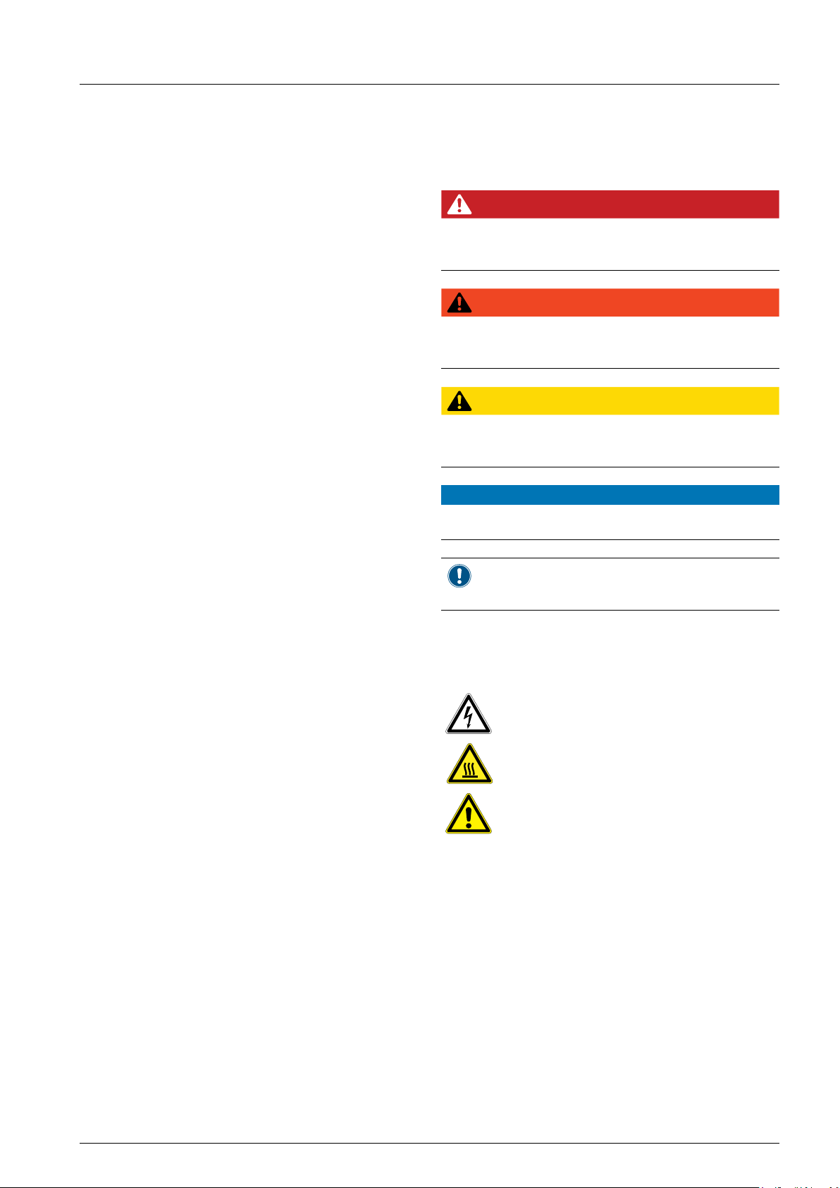
1.3 Warnings and symbols
Where hazards may arise when working with the solar
inverter, the following hazard levels and symbols are
used to indicate these hazards:
DANGER
DANGER indicates a hazardous situation
which, if not avoided, will result in death or
serious injury.
WARNING
WARNING indicates a hazardous situation
which, if not avoided, could result in death or
serious injury.
CAUTION
CAUTION indicates a hazardous situation
which, if not avoided, could result in minor or
moderate injury.
NOTICE
ATTENTION is used to address practices not
related to physical injury.
1.2 Target audience of this manual
This manual is aimed at qualied electricians who
have received a sufcient training to apply safe meth-
ods of work to install a micro-generator in compliance
with the requirements of the applying standard.
Only chapter “9 Measurements and statistics”,
p. 85 is relevant to the operator. All other activities
may only be performed by qualied electricians.
A note provides general information on using
the solar inverter. A note does not indicate
hazardous situations.
Where required, further, supplementary warning
symbols are used. Type and source of the hazard is
explained in the safety instructions or warnings.
This symbol is a warning of a risk of
electric shock due to high voltage.
The symbol is a warning of a hot surface.
This symbol is a warning of general
hazards.
Installation and Operation Manual for RPI M50A
5
1. About this manual
1.4 Conventions used in this manual
Order of instructions
Numbered instructions must be performed in the
specied order.
1. First instruction step
→ When the solar inverter reacts to a step, this
reaction is marked with an arrow.
2. Second instruction step
3. Third instruction step
Instructions consisting of only one step or when the
order of the instruction steps is not important, are
shown as follows:
► Instruction step
► Instruction step
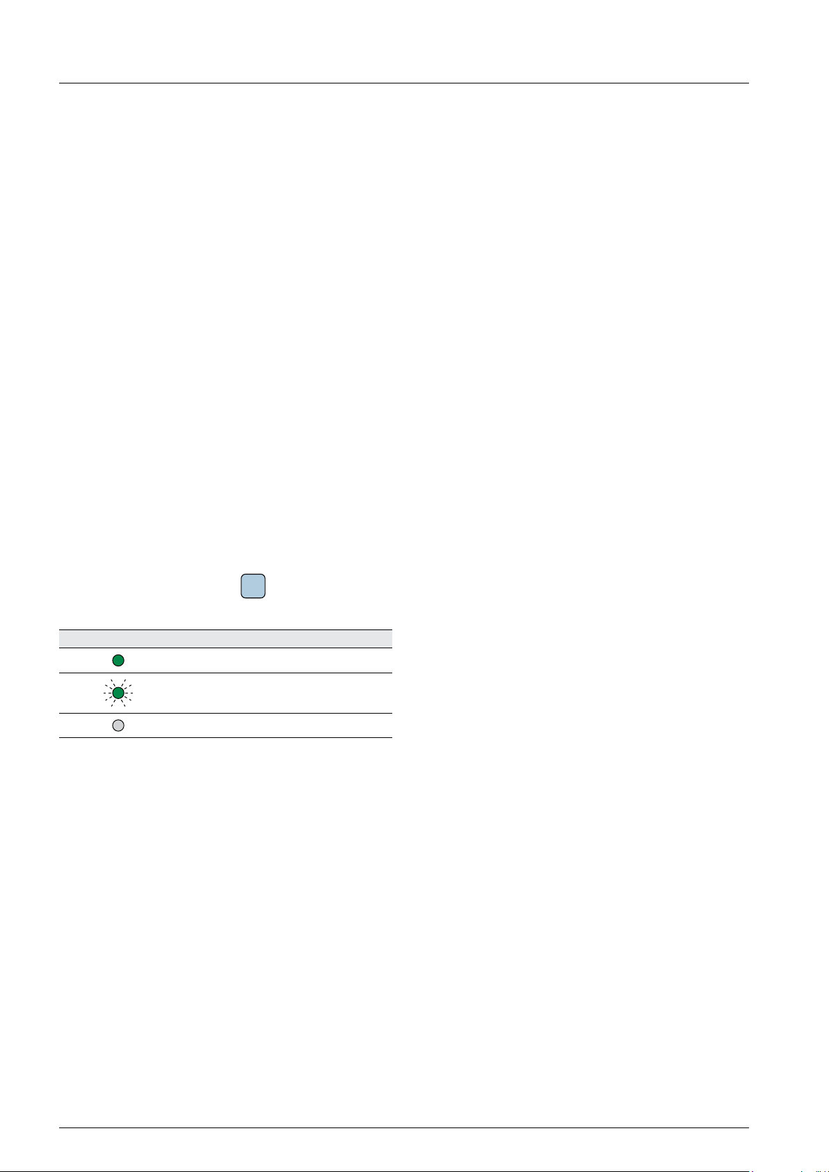
Device buttons and LEDs
Device buttons and LEDs are shown in this manual as
follows:
Buttons on the solar inverter:
LEDs on solar inverter:
LED symbol Meaning
Information on Display
Information shown on the solar inverter display
includes menus, settings and messages.
This information is shown in this manual as follows:
Menu names: User settings menu
Parameter names: Cos phi parameter.
AlArm LED
LED stays on.
LED ashes.
LED is off.
ESC
button.
6
Installation and Operation Manual for RPI M50A
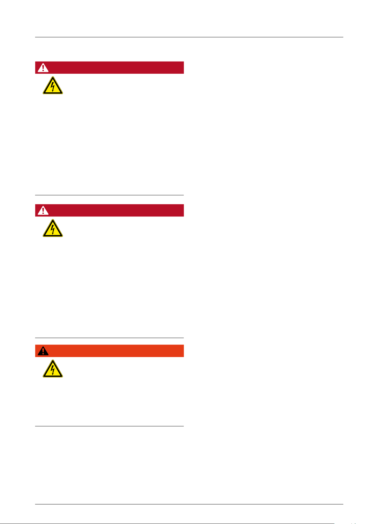
2. General safety instructions
2. General safety instructions
DANGER
High electrocution
Potentially fatal voltage is applied to
the solar inverter during operation. This
potentially fatal voltage is still present
for 10 seconds after all power sources
have been disconnected.
► Always disconnect the inverter from
power before installation, open the
AC/DC isolating switch and make
sure neither can be accidentally
reconnected.
► Only the cover from the fuse section
may be removed. Never open other
parts of the inverter.
► Wait at least 10 seconds until the
capacitors have discharged.
DANGER
High electrocution
Potentially fatal voltage may be applied to the DC connections of the solar
inverter. When light is falling on solar
modules, they immediately start producing energy. They do so, even when
the sun is not shining.
► Never disconnect the solar modules
when the solar inverter is powered.
► First switch off the grid connection
so that the solar inverter cannot
feed energy into the grid.
► Turn the AC/DC isolating switch to
position OFF.
► Make sure the DC connections can-
not be accidentally touched.
WARNING
High electrocution
When you remove the cover from the
fuse section, protection degree is no
longer IP65.
► Remove the cover only when it is
really necessary.
► Do not remove the cover when it is
raining and the inverter is wet.
► Close the cover tightly after work.
● The solar inverter can be safely and normally
operated if installed and used in accordance with
this manual (see IEC 62109-5.3.3). Delta Energy
Systems is not responsible for damage incurred
by failure to observe the installation and operating instructions in this manual. For this reason, be
sure to observe and follow all instructions!
● Installation and commissioning may only be per-
formed by qualied electricians using the installation and commissioning instructions found in this
manual.
● The solar inverter must be disconnected from
power and the solar modules before any work on
it can be performed.
● The solar inverter has a high leakage current
value. The ground wire must be connected before
commissioning.
● Do not remove any warning signs that the manu-
facturer has installed on the solar inverter.
● Improper handling of the solar inverter may result
in physical injury and damage to property. For
this reason, observe and follow all general safety
instructions and warnings.
● The solar inverter contains no components that
must be maintained or repaired by the operator or
installer. All repairs must be performed by Delta
Energy Systems. Opening the cover will void the
warranty.
● Do not disconnect any cables when the solar
inverter is powered due to risk of a fault arc.
● To prevent lightning strikes, follow the relevant
regulations applicable in your country.
● The surface of the solar inverter can become very
hot during operation. Use safety gloves when
working on the solar inverter.
● The solar inverter is very heavy. The solar inverter
must be lifted and carried by at least three people.
● Only devices in compliance with SELV
(EN 69050) may be connected to the RS485 and
USB interfaces.
● All connections must be sufciently insulated in
order to comply with the IP65 protection rating.
Unused connections must be closed by placing
cover caps on the solar inverter.
Installation and Operation Manual for RPI M50A
7

3. Intended use
3. Intended use
The solar inverter may only be used as intended.
Proper use of the solar inverter meets the following
criteria:
● Use in stationary PV systems connected to the
local power grid for converting the direct current in
the PV system to alternating current and feeding it
into the grid
● Use within the specied power range (see
“13 Technical data”, p. 105) and under the
specied ambient conditions (see “5 Planning the
installation”, p. 18).
Any of the following uses of the solar inverter is considered improper:
● Isolated operation. The solar inverter has anti-
islanding and other monitoring features.
● Use in mobile PV systems.
8
Installation and Operation Manual for RPI M50A
3. Intended use
Installation and Operation Manual for RPI M50A
9
4. Product overview
Europe
4. Product overview
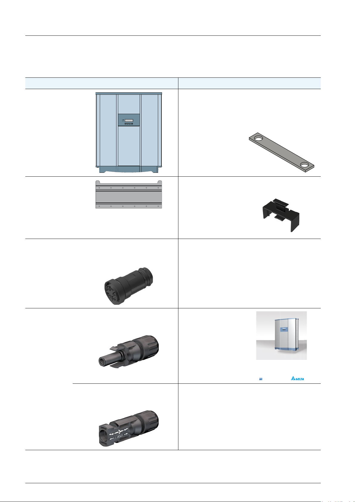
4.1 Scope of delivery
Part Qty Image/Description Part Qty Image/Description
Inverter 1
DC bus bar 2 Used when the solar mod-
ules have to be grounded
and for connecting the
two DC inputs to one MPP
tracker.
Mounting plate 1 DC Fuse holder 1 Used when the solar mod-
ules have to be grounded.
AC plug 1 China Aviation Optical-
Electrical Technology Co.
PVE5T125KE36
Screw for
grounding the
inverter housing
1 An appropriate screw with
washer, washer spring
and toothed ring is already
mounted to the inverter
DC plugs 10 Multi-Contact MC4 plug for
DC+ (32.0017P0001-UR for
2
4/6 mm
)
10 Multi-Contact MC4 plug for
DC– (32.0016P0001-UR for
4/6 mm2)
Quick Installation Guide and
General Safety
Instructions
1
Installation and Operation Manual
RPI M50A
10
Installation and Operation Manual for RPI M50A
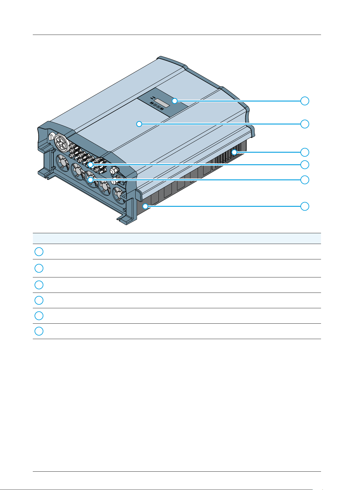
4.2 Components and connectors
2
4. Product overview
1
2
3
4
5
No. Component / connector Description
Display, buttons, status LEDs See “4.3 Display, buttons, status LEDs”, p. 12
1
String fuses and AC/DC overvoltage protection
Air inlets See “4.5 Air inlets and fans”, p. 13
3
Electrical connectors See “4.6 Electrical connectors”, p. 14
4
Fans See “4.5 Air inlets and fans”, p. 13
5
Type label See “4.7 Information on the type label”, p. 17
6
See “4.4 String fuses and AC/DC surge protection
device”, p. 12
6
Installation and Operation Manual for RPI M50A
11
4. Product overview
GrID
AlArm
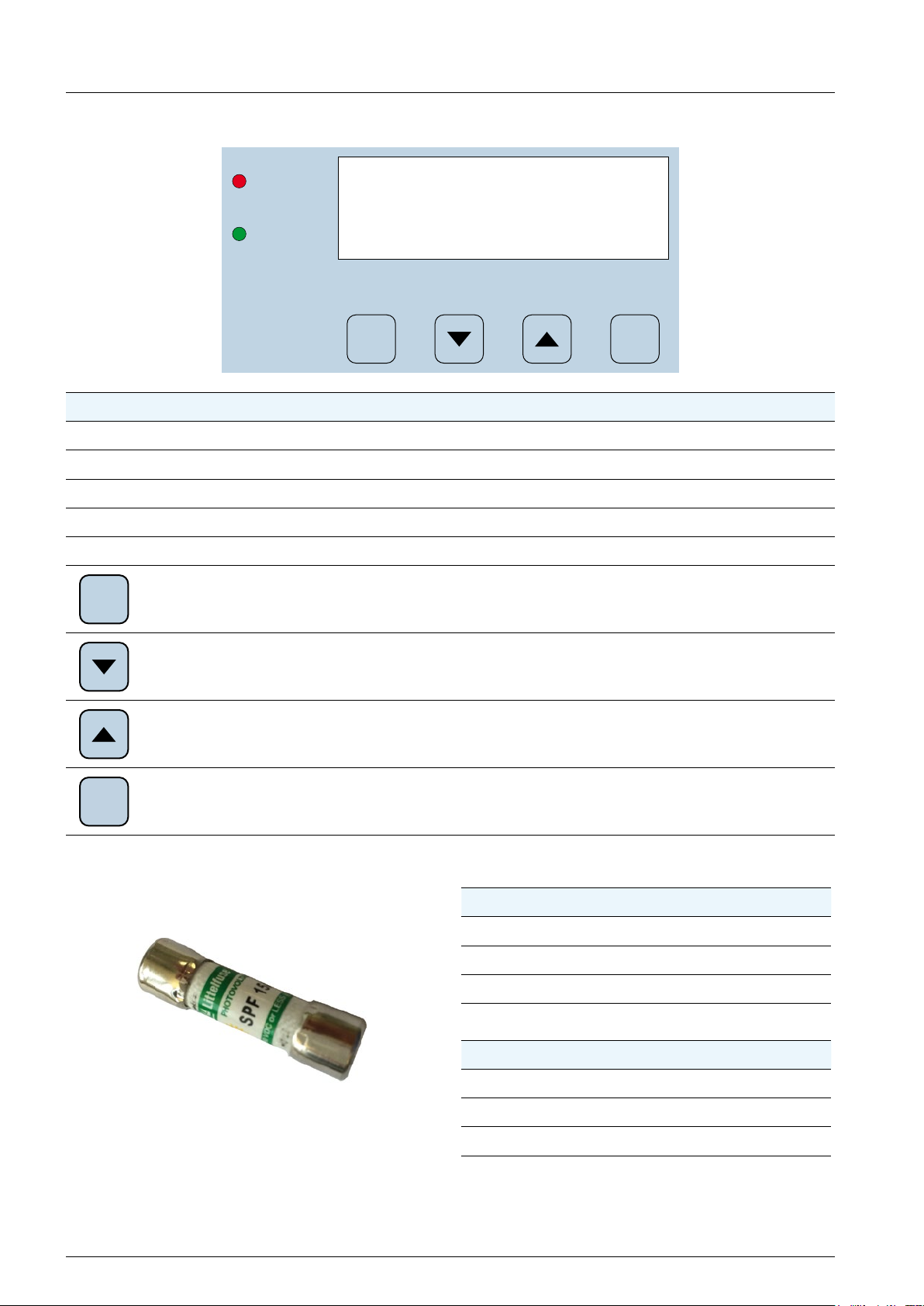
4.3 Display, buttons, status LEDs
Alarm
Grid
ESC ENT
Label Designation Usage
LEDs
Buttons
ESC
ENT
Grid Green; lights up when the inverter feeds into the grid
Alarm Red; indicates and error, fault, or warning
Escape Exit current menu. Cancel value setting.
Move down Move downwards in menu. Set value (decrease).
Move up Move upwards in menu. Set a value (increase).
Enter
Select menu item. Open con gurable value for editing. Finish editing
(adopt set value).
4.4 String fuses
The RPI M50A is equipped with string fuses on the
DC side.
Type
Manufacturer Littelfuse
Part number 0SPF015.T
12
Rate current 15 A
Rate voltage 1000 V
or
Manufacturer Hollyland
Part number 10GPV15UO
Rate current 15 A
Rate voltage 1000 V
Installation and Operation Manual for RPI M50A
4. Product overview
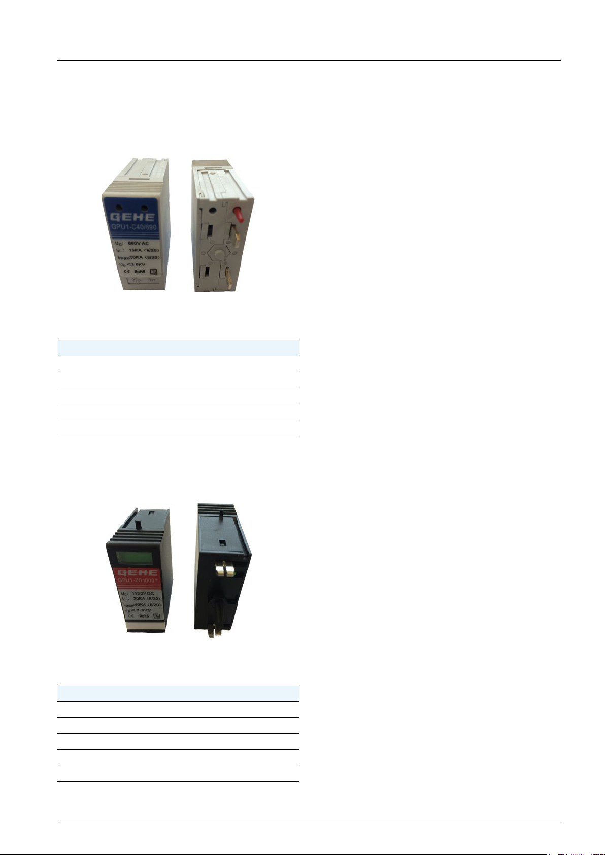
4.5 Surge protection devices
4.5.1 AC side
The M50A_120 additionally has surge protection
devices type 2 on the AC and the DC side.
Type
Manufacturer GEHE
Part number GPU1-C40/690
Voltage U
Current I
Current I
Voltage U
C
n
max
P
690 V
AC
15 kA (8/20)
30 kA (8/20)
≤ 2.5 kV
4.6 Air inlets and fans
Air is intaken from the environment through the air
inlets on the upper left and upper right side of the
inverter. The air is used to cool the inverter. The
warmed-up air is ejected at the fans on the bottom
side of the inverter.
For a detailed description of the cooling principle, see
“5.3 Ambient conditions and air circulation”, p. 19.
For a detailed description how to clean or replace the
fans, see “11. Maintenance”, p. 95.
4.5.2 AC side
The M50A_120 additionally has surge protection
devices type 2 on the AC and the DC side.
Type
Manufacturer GEHE
Part number GPU1-ZS1000*
Voltage U
Current I
Current I
Voltage U
C
n
max
P
1120 V
DC
20 kA (8/20)
40 kA (8/20)
≤ 3.9 kV
Installation and Operation Manual for RPI M50A
13
4. Product overview
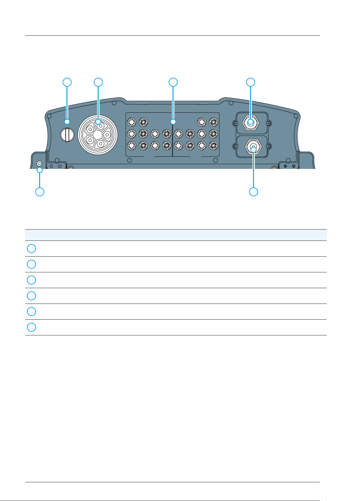
4.7 Electrical connectors
4.7.1 Overview
1 2 3 4
+– +– +– +–
DISCONN.
AC/DC
ON
DC 1 DC 2
AC OUTPUT DC INPUT
OFF
6 5
Fig. 4.1: Overview electrical connectors
No. Component / connector Description
AC/DC disconnection switch See “4.6.2 AC/DC disconnection switch”, p. 15
1
2
AC connector (AC output) See “4.6.3 AC connector (AC output)”, p. 15
DC connectors (DC inputs) See “4.6.4 DC connectors (DC inputs)”, p. 15
3
Communication port 1 See “4.6.5 Communication port 1”, p. 15
4
COMM.
Communication port 2 See “4.6.6 Communication port 2”, p. 16
5
Grounding screw See “4.6.7 Grounding connection”, p. 16
6
14
Installation and Operation Manual for RPI M50A
4. Product overview
+– +– +– +–
+–
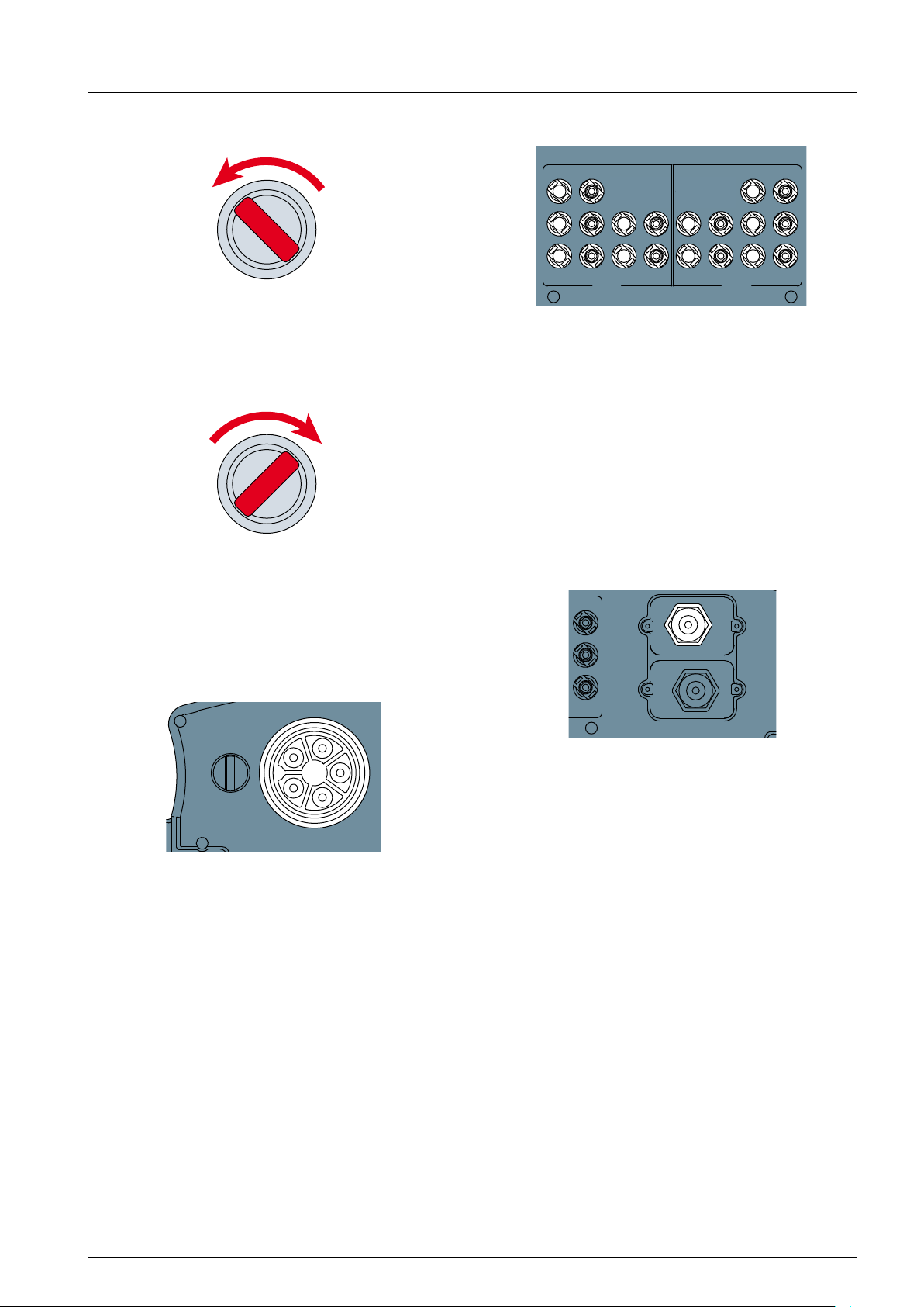
4.7.2 AC/DC disconnection switch
OFF ON
DISCONN AC/DC
The inverter is disconnected from the grid (AC) and
the solar modules (DC) when the AC/DC disconnec-
tion switch is in position OFF.
OFF ON
DISCONN AC/DC
4.7.4 DC connectors (DC inputs)
DC 1 DC 2
DC INPUT
The DC connectors (DC inputs) are used for connecting inverter to the solar module string(s).
Connector type:
● Multi-contact MC4
● 10 pairs with female socket for DC+ and male
socket for DC–.
● 10 pairs of plugs are delivered with the inverter
For technical specications, see “13. Technical data”,
p. 105.
4.7.5 Communication port 1
The inverter is connected to the grid (AC) and the
solar modules (DC) when the AC/DC disconnection
switch is in position ON.
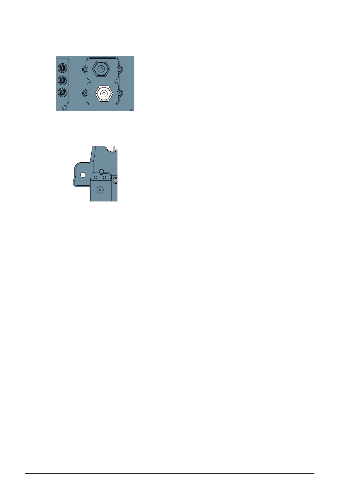
4.7.3 AC connector (AC output)
DISCONN.
AC/DC
ON
AC OUTPUT
OFF
The AC connector is used for connecting the inverter
to the grid.
Usage of the AC connection:
● Feeding AC current into the grid.
● Powering up the display when no DC voltage is
available via the DC connectors (DC inputs).
The inverter can be connected to:
COMM.
Functions of Communication port 1:
● 1 x RS485 in/out (e.g. for connecting to a datalog-
ger)
● 6 x Digital inputs (e.g. for connecting to a ripple
receive controller)
● 2 x Dry contacts (e.g. for connecting to an exter-
nal relais)
● 1 x VCC contacts (e.g. for connecting to an exter-
nal relais)
For a detailed description, see “6.7 Connecting com-
munication port I (optional)”, p. 45.
● 5-wire grid sytems 3P4W (L1, L2, L3, N, PE)
● 4-wire grid systems 3P3W (L1, L2, L3, PE).
AC plug type:
China Aviation Optical-Electrical Technology Co.
PVE5T125KE36
The AC plug is delivered with the inverter.
Installation and Operation Manual for RPI M50A
15
4. Product overview
+–
DISCONN.
4.7.6 Communication port 2
COMM.
Communication port 2 is not available on this inverter.
4.7.7 Grounding connection
AC/DC
The grounding connection is used for grounding the
housing of the inverter.
The grounding screw (M6) with washer spring,
washer and toothed ring is already mounted to the
inverter.
For a detailed description, see “6.3 Grounding the
inverter housing”, p. 39.
16
Installation and Operation Manual for RPI M50A
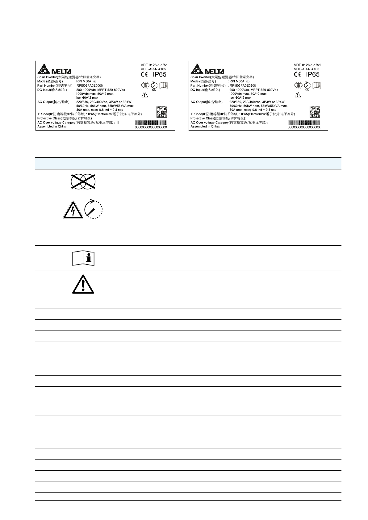
4.8 Information on the type label
Fig. 4.2: RPI M50A_120 type label Fig. 4.3: RPI M50A_122 type label
Information on type label Description
This inverter has no transformer.
Risk of death by electrocution
Potentially fatal voltage is present when the inverter is in operation that remains for
10 seconds after being disconnected from power.
10 s
Never open the inverter. The inverter contains no components that must be maintained or repaired by the operator or installer. Opening the cover will void the warranty.
4. Product overview
Read the manual delivered with the inverter before working with the inverter and
follow the instructions contained in the manual.
The housing of the inverter must be grounded if this is required by local regulations.
DC Input
200-1000Vdc DC input voltage range
MPPT 520-800Vdc MPP input voltage range with full power (with symmetrical load)
1000Vdc Maximum DC input voltage
50A*2 max. Maximum DC input current per DC input (50 A for each DC input)
Isc: 60A*2 max. DC short circuit current
AC Output
220/380, 230/400 Vac AC Nominal voltage
3P3W or 3P4W The inverter can be connected to 3-wire systems (3 phases + PE) and 4-wire sys-
tems (3 phases + N + PE)
50/60 Hz AC Nominal frequency
50kW nom. Nominal active power
55kW/55kVA Maximum active/reactive power
80A max. Maximum AC current
cos φ 0.8 ind ~ 0.8 cap Range of cos φ
IP Code: IP65 (Electronics) Protection degree for the electronics according to EN 60529
Protective Class: I Safety class according to EN 61140
AC Over voltage category: III AC overvoltage category according to IEC 62109-1
Installation and Operation Manual for RPI M50A
17
5 Planning the installation
?
?
?
?
✔
✘ ✘
5. Planning the installation
NOTE
This chapter is for planning the installation only and is not related to do any
real actions.
Some of the actions can be dangerous. Chapter “6. Installation”, p. 37
describes all actions and the possibly
related risks in detail.
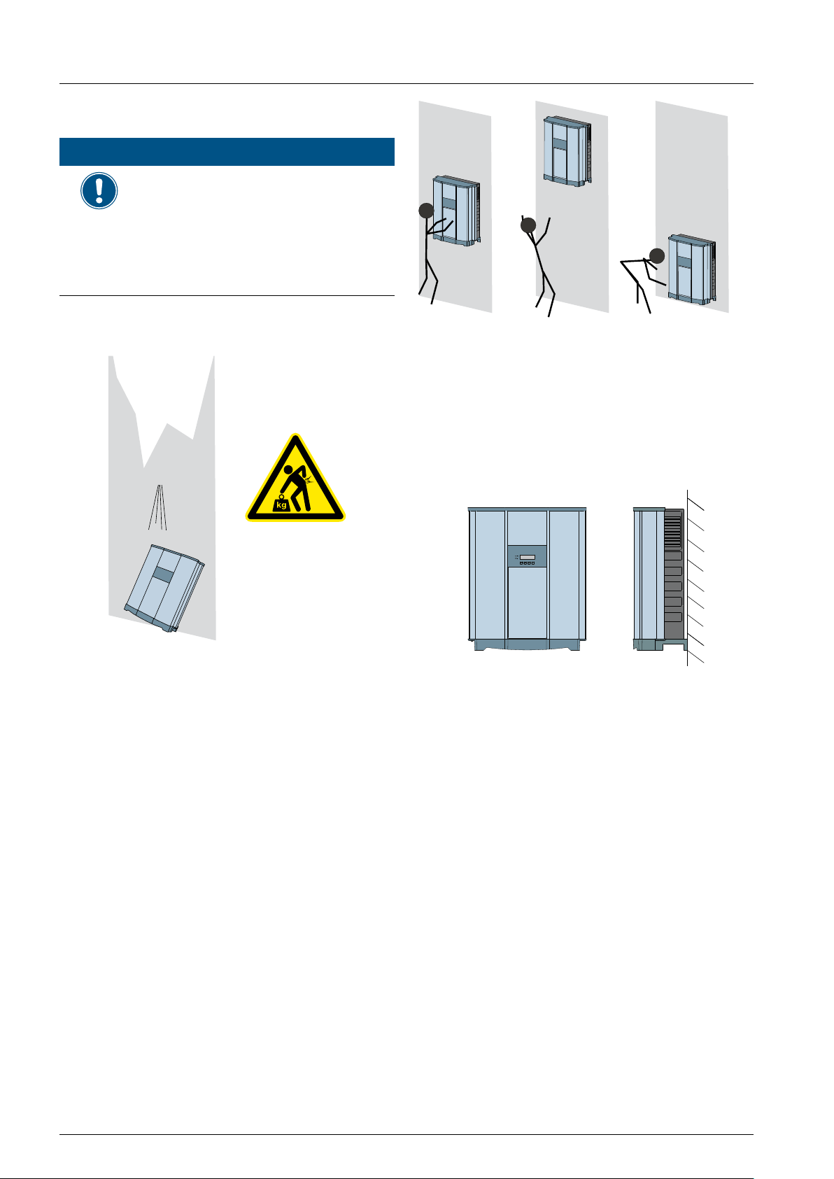
5.1 Where to mount the solar inverter
Fig. 5.2: Where to mount the inverter 2
► Mount the solar inverter so that the LEDs and dis-
play can be easily seen and that the buttons can
be operated. Make sure the reading angle and
installation height are sufcient.
74 kg
Fig. 5.1: Where to mount the inverter 1
► The solar inverter is very heavy. The solar inverter
must be lifted and carried by at least three people.
► Always use the mounting plate supplied with the
solar inverter.
► Check that the wall is capable of bearing the
heavy load of the device.
► Use dowels and screws that are suitable for the
wall material and the heavy weight.
► Mount the solar inverter on a vibration-free wall to
avoid disruptive vibrations.
► Possible noise emissions can be disruptive when
the device is used in living areas or in buildings
with animals. Therefore, choose your installation
location carefully.
Fig. 5.3: Mounting orientation
► Mount the solar inverter vertically.
18
Installation and Operation Manual for RPI M50A
5 Planning the installation
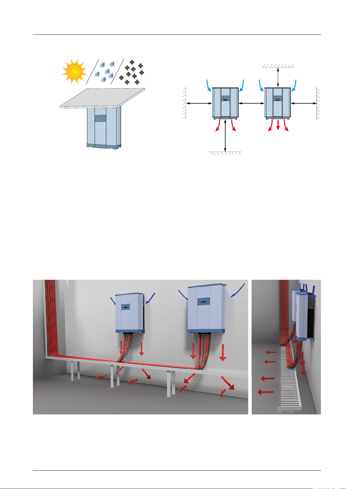
5.2 Outdoor installations
Fig. 5.4: Outdoor installations
► The solar inverter has protection degree IP65 and
can be installed indoors or in protected outdoor
areas (that means outdoor but protected by a roof
against direct sun, rain or snow).
5.3 Ambient conditions and air circulation
>20 cm
>30 cm>30 cm >30 cm
>80 cm
Fig. 5.5: Mounting distances and air circulation
► Ensure adequate air circulation. Hot air must be
able to dissipate downward. Keep enough space
around each inverter.
► Do not install inverters directly above one another.
Otherwise, the lower inverter is warmed up by the
upper one.
► Consider the operating temperature range (see
“13. Technical data”, p. 105).
When the operating temperature range is exceeded, the solar inverter reduces the amount of power
generated.
Installation and Operation Manual for RPI M50A
Fig. 5.21: Air fl ow around solar inverter
19
5 Planning the installation
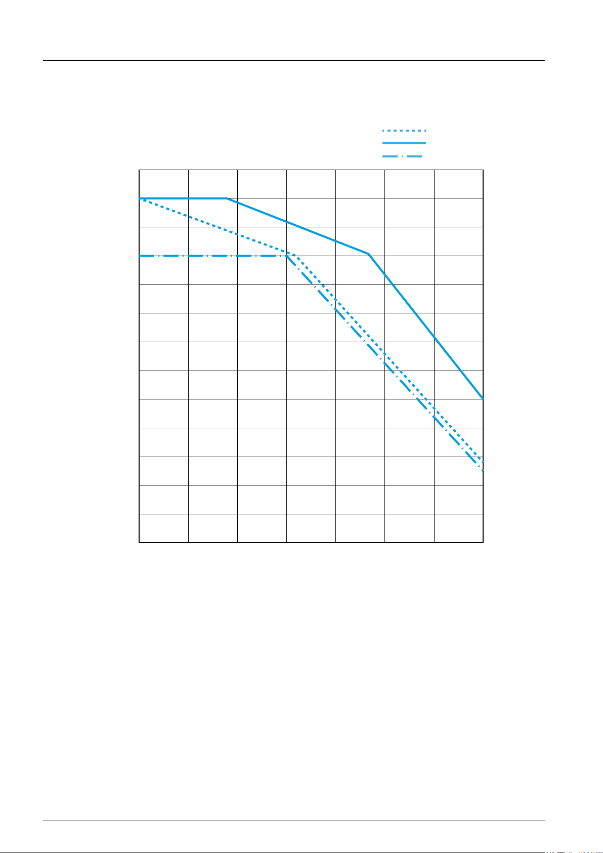
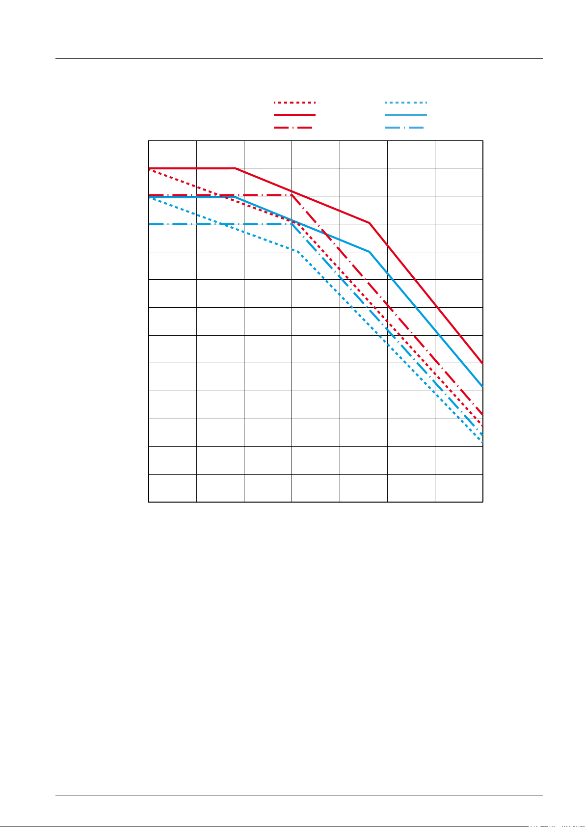
5.4 Temperature derating curves
P/P
(Pn = 50 kW)
n
115%
110%
105%
100%
95%
90%
S [VA] = P [W]
800 V
600 V
520 V
DC
DC
DC
85%
80%
75%
70%
65%
60%
55%
50%
25 30 35 40 45 50 55 60
Ambient temperatures [°C]
Fig. 5.6: Temperature derating curve (cos φ = 1.0)
20
Installation and Operation Manual for RPI M50A
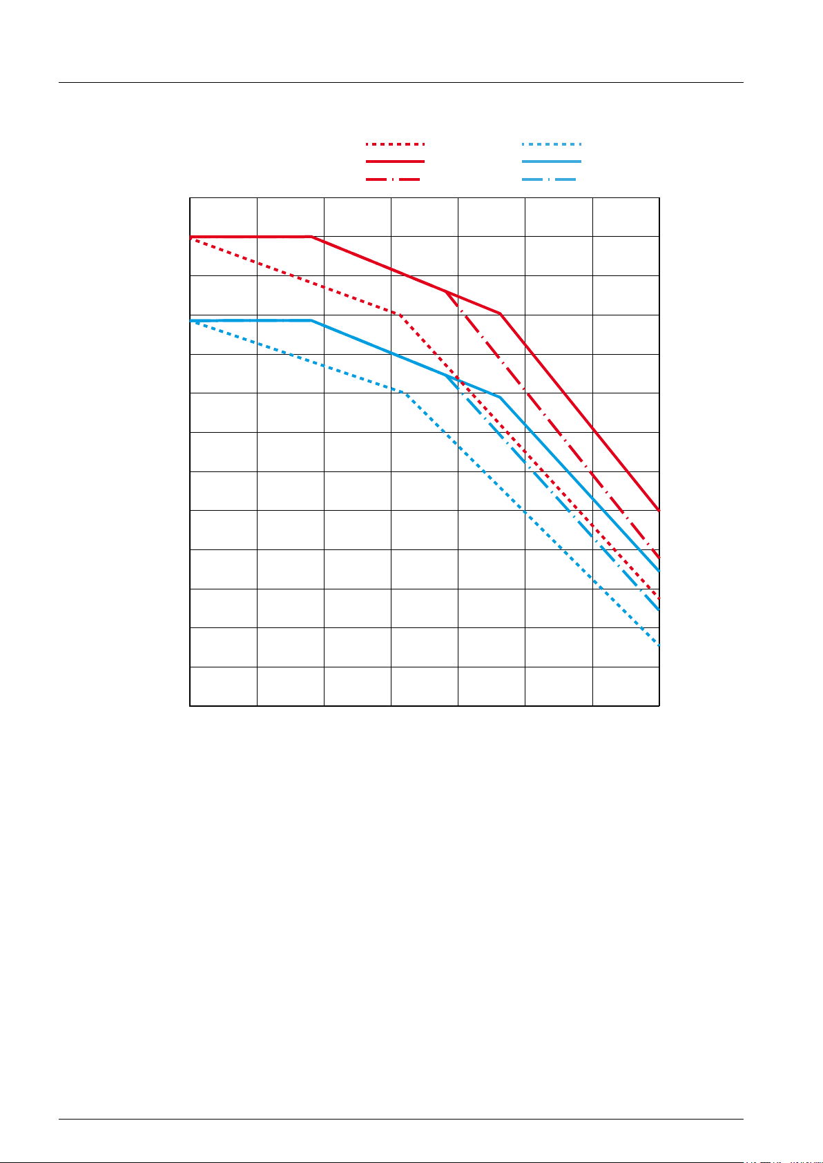
P/P
Ambient temperatures [°C]
(Pn = 50 kW)
n
115%
110%
105%
100%
95%
90%
85%
5 Planning the installation
P [W]S [VA]
800 V
600 V
520 V
DC
DC
DC
800 V
600 V
520 V
DC
DC
DC
80%
75%
70%
65%
60%
55%
50%
25 30 35 40 45 50 55 60
Fig. 5.7: Temperature derating curve (cos φ = 0.95)
Installation and Operation Manual for RPI M50A
21
5 Planning the installation
Ambient temperatures [°C]
P/P
(Pn = 50 kW)
n
115%
110%
105%
99%
95%
90%
85%
800 V
600 V
520 V
DC
DC
DC
P [W]S [VA]
800 V
DC
600 V
DC
520 V
DC
80%
75%
70%
65%
60%
55%
50%
25 30 35 40 45 50 55 60
Fig. 5.8: Temperature derating curve (cos φ = 0.90)
22
Installation and Operation Manual for RPI M50A
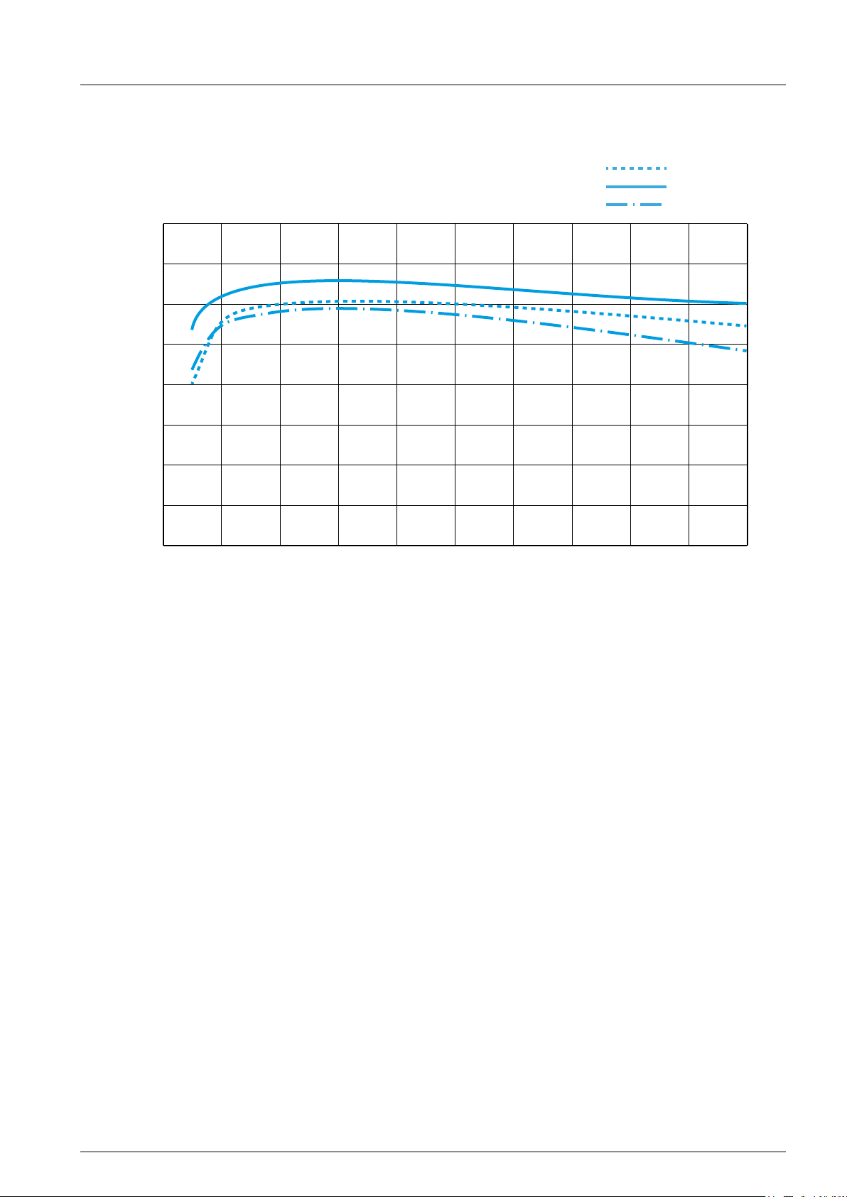
5.5 Efciency curve
Efficiency
100%
99%
98%
97%
96%
95%
94%
5 Planning the installation
800 V
DC
600 V
DC
520 V
DC
93%
92%
15 2050 10 25 30 35 40 45 50
Power [kW]
Fig. 5.9: Efciency curve
Installation and Operation Manual for RPI M50A
23

5 Planning the installation
5.6 Dimensions
107
30
31
158.7
172.8
25
82
Fig. 5.10: Dimensions of mounting plate
612 278
460
Fig. 5.11: Dimensions of inverter
740
24
Installation and Operation Manual for RPI M50A
5 Planning the installation
G N L1 L3L2
N
L1
L2
L3
PE
To solar inverter AC
plug
5.7 AC connection
Always adhere to the specic regulations applicable in
your country or region.
Always adhere to the specic regulations dened by
your grid operator.
For the safety of the user and for the security of your installation, install required safety and protection devices that
are applicable for your installation environment (example:
automatic circuit breaker and/or overcurrent protection
equipment).
Use the proper upstream circuit breaker to protect the
inverter:
Model Upstream Circuit Breaker
RPI M50A 100 A
2
NOTE
The value of the tripping current mainly
depends on the quality of the solar
modules, the size of the PV array and
environmental conditions (e.g. humidity). The tripping current of the residual
current device must not be less than
the specied minimum tripping current.
Permitted earthing systems
Earthing
System
Permitted Yes Yes Yes Yes No
AC grid voltage requirements
3P3W 3P4W
L1-L2 400 V
L1-L3 400 V
L2-L3 400 V
TN-S TN-C TN-C-S TT IT
± 20% L1-N 230 VAC ± 20%
AC
± 20% L2-N 230 VAC ± 20%
AC
± 20% L3-N 230 VAC ± 20%
AC
Fig. 5.12: Where to place upstream circuit breakers
in the system
The inverter is not capable of feeding in DC residual currents due to its design. It fullls this requirement in accordance with DIN VDE 0100-712.
The possibilities of faults were examined by Delta
without taking the integrated RCMU (residual-current
monitoring unit) into account. When examining
these faults in terms of the current valid installation
standards, no danger in combination with a type A
upstream residual-current device (RCD) can occur.
Therefore faults that would otherwise require the use
of a type B residual-current device due to the inverter
can be excluded.
The integrated all-pole sensitive RCMU is certied
according VDE 0126 1-1/A1:2012-02 §6.6.2 for a tripping current of 300 mA. RCD Type A can be used for
this inverter, according to the following table.
M50A
Minimum tripping current of the
mA ≥300
RCD
Installation and Operation Manual for RPI M50A
25
5 Planning the installation
5.8 DC connection
NOTICE
Machine and equipment damage may occur.
Exceeding the maximum current per DC input can cause an overheating of the DC inputs.
► Always consider the maximum current of the DC inputs when planning the installation.
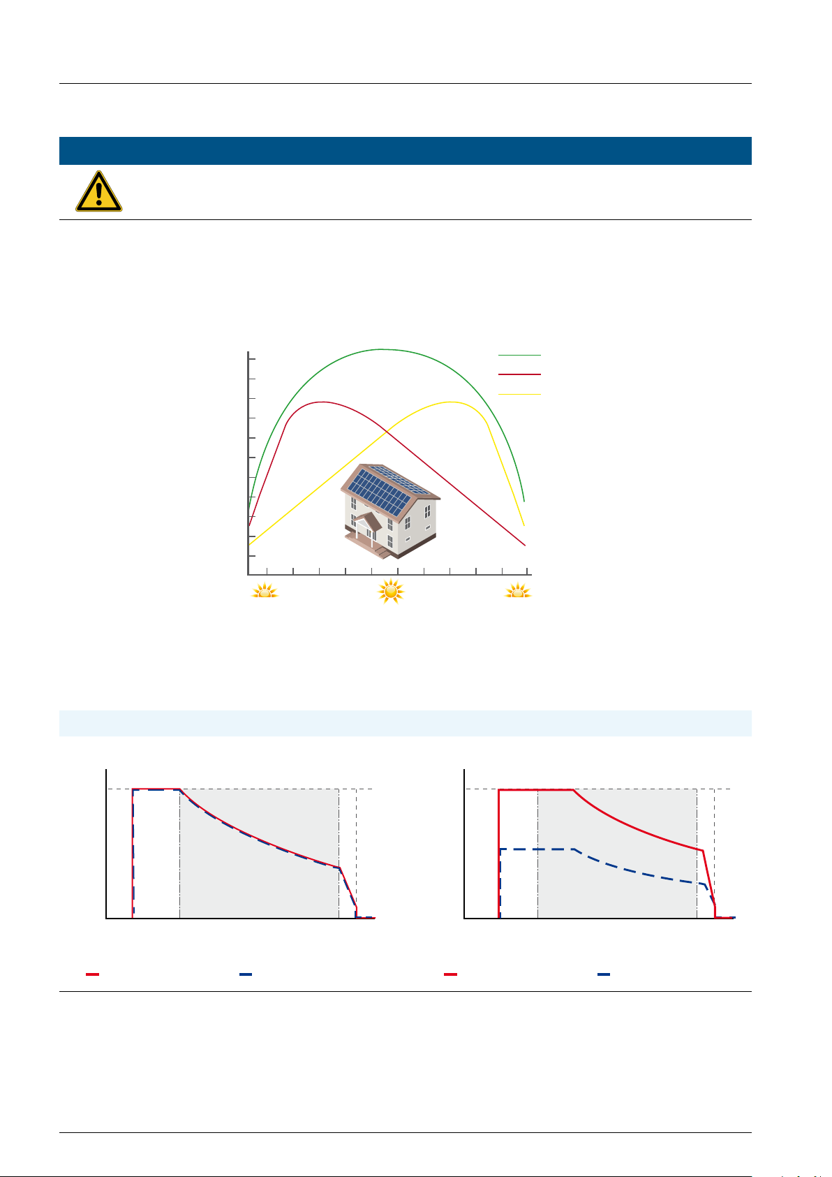
5.8.1 Symmetrical and asymmetrical power input
The inverter operates using two separate MPP trackers that can handle both symmetrical and asymmetrical
power input. This allows you to set up complex PV system designs. For example: east/west-facing roof (asymmetric load) or a south facing roof such as a dormer (asymmetrical load).
Total
East Roof
West Roof
kW
East West
8:00 13:00 18:00
Fig. 5.13: Concept of 2-MPP-tracker system for asymmetrical power input
The following gures explain how symmetrical and asymmetrical power input is handled:
Symmetrical power input Asymmetrical power input
Input Current
I
max
Max. Power MPPT Range
Input Current
I
max
Max. Power MPPT Range
26
U
startup
U
max
U
startup
Input Voltage
Input Current DC 1 Input Current DC 2
Input Current DC 1 Input Current DC 2
Fig. 5.14: I-U curve for symmetrical and asymmetrical power input (schematic diagrams)
Installation and Operation Manual for RPI M50A
U
max
Input Voltage
5 Planning the installation
COMM.
For currents and voltages see “13. Technical data”, p. 105.
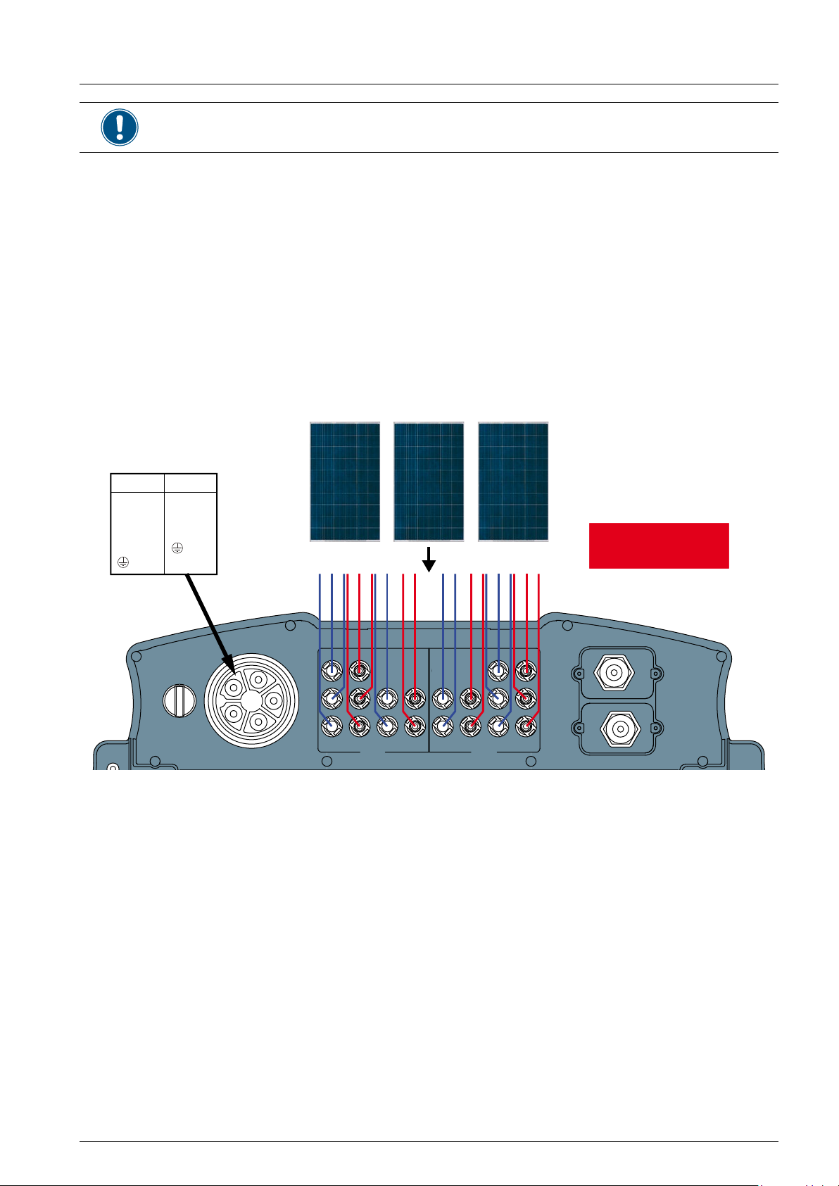
5.8.2 Use with solar modules that do not need to be grounded.
When you use PV modules that do not need to be
grounded, you can connect the DC inputs separately
or in parallel.
“Separate DC inputs” means each DC input is connected to a separate MPP tracker. “Parallel DC
inputs” means both DC inputs are connected to one
MPP tracker. With parallel DC inputs you cannot realize asymmetrical power inputs.
PV arrays can be connected to the inverter directly or externally parallel connection at DC distribution box.
PV array
AC wiring
3P3W 3P4W
1 - L1
2 - L2
3 - L3
4 - N
1 - L1
2 - L2
3 - L3
- PE
5 - PE
DISCONN.
AC/DC
ON
OFF
DC wiring
+– +– +– +–
DC 1 DC 2
AC OUTPUT DC INPUT
Fig. 5.15: System design with fl oating DC inputs
Separate or
parallel DC inputs
Installation and Operation Manual for RPI M50A
27
5 Planning the installation
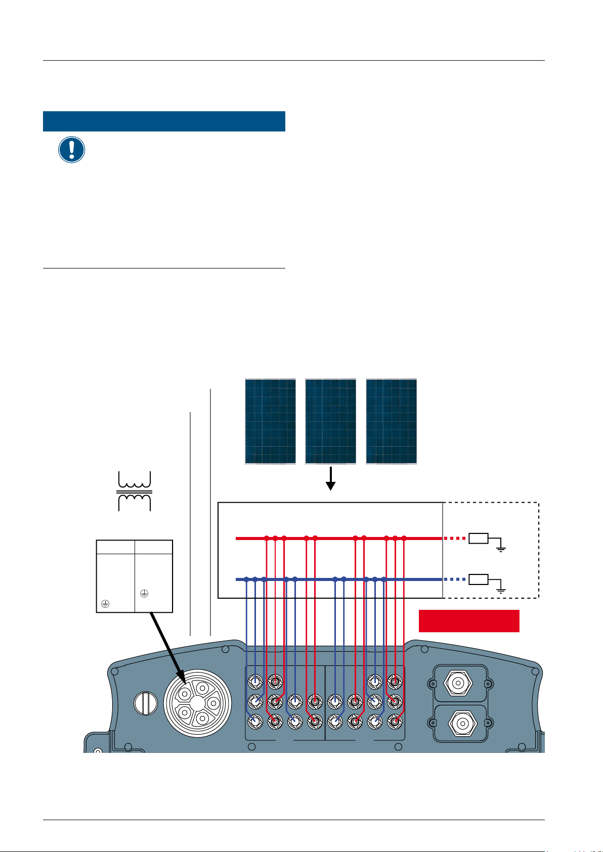
5.8.3 Use with solar modules that have to be grounded.
NOTICE
Machine and equipment damage
may occur.
► When the DC inputs are grounded,
all of the strings must be connected
in parallel and then connected to
the inverters.
► Additionally, an external isolation
transformer must be installed on
the AC side, otherwise, damage will
result and the inverter will not work
properly.
When the DC inputs are grounded, all of the strings
must be connected in parallel and then connected to
the inverter(s).
When the solar modules need to be grounded, an
external isolation transformer has to be implemented
to the AC side of the PV system as shown in Fig.
5.16, p. 28.
Depending on the DC connection type, different settings for insulation detection are needed, see “8.7
Insulation mode and insulation resistance”, p. 59.
You have to prepare the inverter for use with
grounded solar modules, see Fig. 5.17, p. 29 and
Fig. 5.18, p. 30. Because you have to remove the
cover of the fuse section, you should do this before
you hang the inverter on the wall and do it in a dry
environment. For a detailed description how to do
this, see “6.5 Connecting to the solar modules (DC)”,
p. 42.
PV array
AC wiring
3-phase, 230/400 V
star or delta connection
Isolated
transformer
Inverter
230/400 V
3P3W 3P4W
1 - L1
2 - L2
3 - L3
4 - N
5 - PE
Utility
OFF
AC
1 - L1
2 - L2
3 - L3
- PE
ON
AC
Distribution Box
+
–
+– +– +– +–
DC wiring
Positive grounding
Z
Negative grounding
Z
Parallel DC inputs only
28
DISCONN.
AC/DC
AC OUTPUT DC INPUT
DC 1 DC 2
COMM.
Fig. 5.16: System design with positive or negative grounding of the solar modules
Installation and Operation Manual for RPI M50A

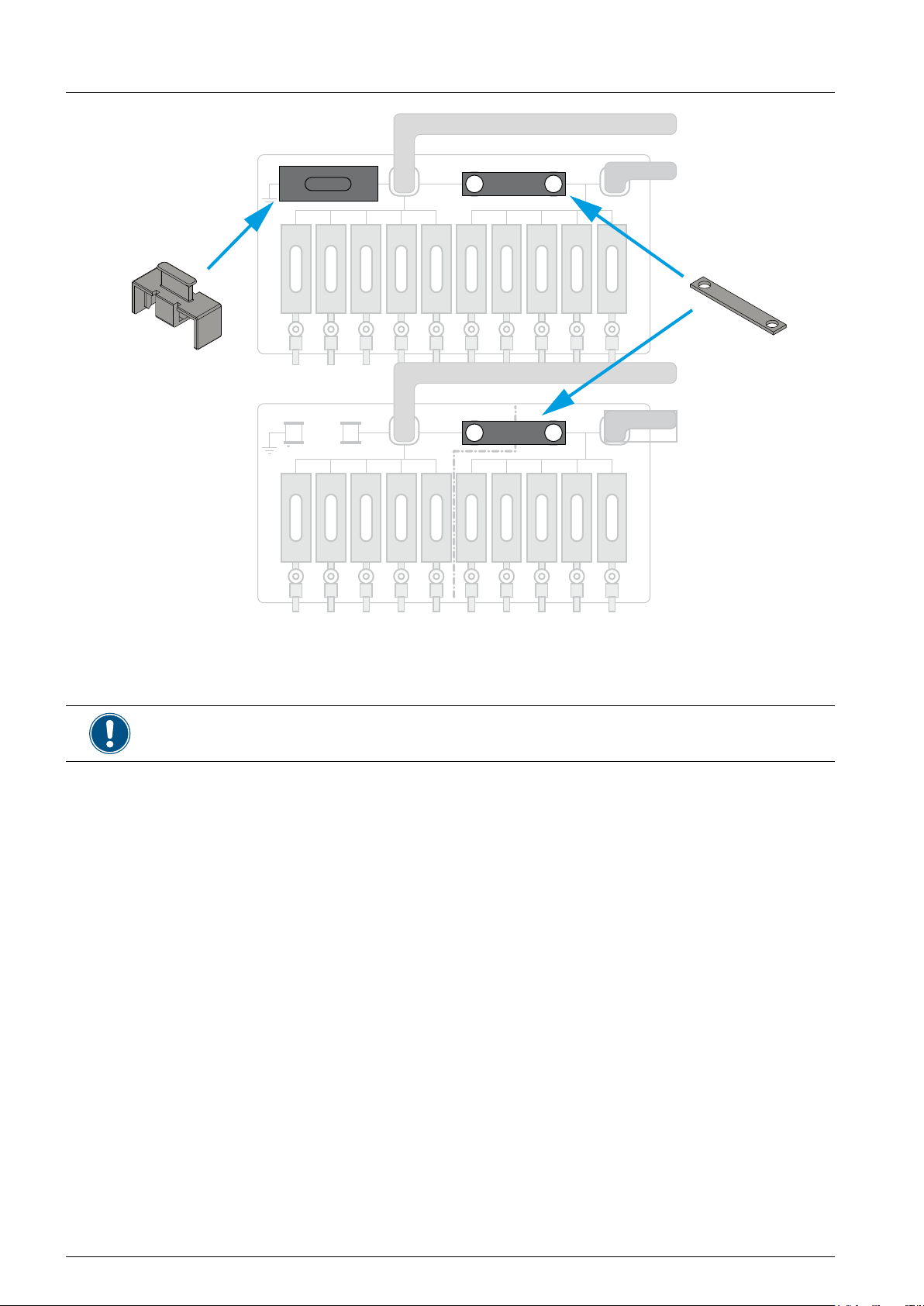
1 x
5 Planning the installation
DC1+
DC2+
1 x
+
Grounding fuse (1 A)
Fig. 5.17: Preparing the inverter for use with minus grounded solar modules
Fuse holder and DC bus bars are delivered with the inverter. The screws are already fastened
inside the inverter. You have to provide a grounding fuse with 1 A.
DC1-
DC bus barFuse holder
DC2-
Installation and Operation Manual for RPI M50A
Installation and Operation Manual for RPI M50A
29
29
5 Planning the installation
1 x
DC1+
DC2+
2 x
+
Grounding fuse (1 A)
Fig. 5.18: Preparing the inverter for use with plus grounded solar modules
Fuse holder and DC bus bars are delivered with the inverter. The screws are already fastened
inside the inverter. You have to provide a grounding fuse with 1 A.
DC1-
DC bus barsFuse holder
DC2-
30
30
Installation and Operation Manual for RPI M50A
Installation and Operation Manual for RPI M50A

5 Planning the installation
5.8.4 Using DC1 and DC2 with only one MPP tracker
When you want to use DC1 and DC2 with only one MPP tracker, you have to prepare the inverter as shown in
Fig. 5.19, p. 31.
Because you have to remove the cover of the fuse section, you should do this before you hang the inverter on
the wall and do it in a dry environment.
DC1+
DC2+
DC1-
DC2-
Fig. 5.19: Preparing the inverter for use with only one MPP tracker
Installation and Operation Manual for RPI M50A
31

5 Planning the installation
5.9 Connecting to a datalogger via RS485
The inverter can be connected to a datalogger via
RS485, e.g. for monitoring, changing settings or software updates.
To ensure the proper work of the data connection,
consider the following recommendation and instructions.
For a detailed description how to perform the activities
described in this section, see “6.7 Connecting commu-
nication port I (optional)”, p. 45.
When you connect a single inverter
● The termination resistor has to be switched on.
When you connect multiple inverters within the
same PV system
● On the last inverter in the chain, the termination
resistor has to be switched on.
● If your datalogger has no internal termination re-
sistor, the termination resistor on the rst inverter
in the chain has to be switched on too.
● To each inverter a different inverter ID has to be
applied. This is necessary, so that the datalogger
or the maintenance software can identify each
inverter in the chain.
● The baud rate has to be the same on each in-
verter.
Cable and wire requirements
● Twisted and shielded cables with 2 solid wires.
● Cable diameter: 5 mm
● Wire cross-section: 1 mm
● The RS485 cables should lay with distance from
the AC cable and the DC cables to avoid interferences.
2
32
Installation and Operation Manual for RPI M50A

5.10 Circuit diagram of string fuses and SPDs
DC1+
DC1–
5 Planning the installation
DC2+
DC2–
DC side AC side
Overvoltage protection category II Overvoltage protection category II
Fig. 5.20: Circuit diagram string fuses and surge protection devices
Installation and Operation Manual for RPI M50A
Installation and Operation Manual for RPI M50A
33
33

5 Planning the installation
5.11 What you need
Beside the parts delivered with the inverter (see “4.1 Scope of delivery”, p. 10), you may need the following
addititional parts and tools.
Part Quantity Image/Description
For mounting the inverter
M6 mounting screws 12 The mounting plate has to be mounted with 12 M6 screws.
Depending on where you mount the inverter (e. g. on a brick wall,
concrete wall, metal frame etc.) you may need additional mounting
material.
This could be:
Wall plugs, washers, washer springs, nuts etc.
For connecting the inverter to the grid (AC)
AC cable - Use properly sized wire to connect to the correct poles (see table)
China Aviation
AC connector
Optical-Electrical
Technology Co.
PVE5T125KE36
Current rating 100 A
Min. / Max. cable diameter 37 ... 44 mm
Min. / Max. wire size 25 ... 35 mm
Recommended torque for terminal
screws
3 Nm
2
AC plug delivered with the inverter can be used with exible copper
cable.
When calculating the cross section of the cable, consider:
● material used
● thermal conditions
● cable length
● type of installation
● AC voltage drop
● power losses in cable
Always follow the system installation requirements dened for your
country!
France: Follow the system installation requirements dened by UTE
15-712-1 regarding minimum cable sections and protections against
overheating due to high currents!
34
34
Germany: Follow the system installation requirements dened by VDE
0100 712 regarding minimum cable sections and protections against
overheating due to high currents!
For a description how to connect the AC cable to the AC connector
see “6.4 Connecting to the grid (AC)”, p. 40.
Installation and Operation Manual for RPI M50A
Installation and Operation Manual for RPI M50A

Part Quantity Image/Description
5 Planning the installation
Wire ferrules (bootlace
pins) and crimping tool
4 or 5 Wire ferrules are needed for the wires of the AC cable to tightly mount
them to the AC connector.
4 (for 3-wire systems with 3 phases + PE)
5 (for 4-wire systems with 3 phases + N + PE)
You should use a crimping tool to fasten the wire ferrules to the wire.
For connecting the inverter to the solar modules (DC)
DC cable and DC plugs
a
10 pairs of DC plugs for the DC cable are delivered with the inverter: 32.0016P0001-UR and
32.0017P0001-UR. Follow the description in the table below if you need additional DC plugs.
b
DC connectors on the
Plugs for DC cable
inverter
DC–
a b
2
mm
4 / 6
^
10 5.5-9 32.0034P0001
mm
3–6 32.0014P0001-UR
5.5-9 32.0016P0001-UR
Multi-Contact
4 / 6 3-6 32.0015P0001-UR
5.5-9 32.0017P0001-UR
DC+
10 5.5-9 32.0035P0001
Safety caps up to 20 Safety caps secure the DC cables to the DC inputs so that they can-
not be removed without a special tool. To remove the safety caps,
an open end spanner is needed. The safety caps must be used in
France. Please check local regulations whether you have to use
safety caps.
Installation and Operation Manual for RPI M50A
Installation and Operation Manual for RPI M50A
35
35

5 Planning the installation
WARNING
Dual Supply
Do not work on this equipment until it is isolated from
both mains and on site generation supplies
Isolate on-site Generating Unit(s) at ………………………………………………….
Isolate mains supply at………………………………………………………
Warning – Only persons authorised by the DNO may remove the main cut out fuse
Part Quantity Image/Description
Open end spanner 1 The open end spanner is used to disconnect the DC cables from the
DC inputs.
For grounding the inverter housing
Cables Typically yellow/green copper cable with minimum wire size 6 mm
has to be used. Always consider local regulation regarding the cable
requirements.
For wiring the communication port
Cables Depending on which connectors you want to use (RS485, dry con-
tacts, digital inputs), you need the appropriate cables with wire size
2
.
1 mm
2
For using the inverter with grounded solar modules
Magnetic screw driver 1 If you need to open the cover of the fuse section, you should use a
magnetic screw driver, so that the screws cannot accidentally fall into
the inverter.
Grounding fuse 1 A grounding fuse with 1 A is needed. The fuse holder is delivered with
the inverter.
Other parts
Labels - Check local regulations whether you have to attach special safety
labels to the inverter.
36
36
Isolate both sources before
carrying out any work
Warning
Two sources of voltage present
- distribution network
- photovoltaic panels
Installation and Operation Manual for RPI M50A
Installation and Operation Manual for RPI M50A

6. Installation
6.1 Safety instructions
DANGER
High electrocution
Potentially fatal voltage is applied to
the solar inverter during operation. This
potentially fatal voltage is still present
for 10 seconds after all power sources
have been disconnected.
► Always disconnect the inverter from
power before installation, open the
AC/DC isolating switch and make
sure neither can be accidentally
reconnected.
► Only the cover from the fuse section
may be removed. Never open other
parts of the inverter.
► Wait at least 10 seconds until the
capacitors have discharged.
6 Installation
WARNING
High electrocution
When you remove the cover from the
fuse section, protection degree is no
longer IP65.
► Remove the cover only when it is
► Do not remove the cover when it is
► Close the cover tightly after work.
WARNING
Heavy weight
The inverter weighs about 73 kg.
► The inverter must be lifted and car-
Read chapter “5. Planning the installa-
tion”, p. 18 and this chapter before
you start installation.
really necessary.
raining and the inverter is wet.
ried by at least three people or with
an appropriate lifting equipment.
Installation and Operation Manual for RPI M50A
37

6 Installation
6.2 Mounting the inverter
WARNING
Heavy weight
► The inverter must be lifted and car-
ried by at least three people or with
an appropriate lifting equipment.
► Always use the mounting plate
delivered with the inverter.
Read chapter “5. Planning the installa-
tion”, p. 18 before you start installa-
tion.
1. Attach the mounting plate with 12 M6 screws to
the wall or to your mounting system. Use the ap-
propriate type and number of screws.
3. Check that the rail of the solar inverter hangs cor-
rectly in the mounting plate.
2. Hang the solar inverter onto the mounting plate.
4. Check that the bottom of the inverter is rmly po-
sitioned against the wall or the mounting system.
Also check that the inverter hangs vertically in all
directions.
38
Installation and Operation Manual for RPI M50A

6.3 Grounding the inverter housing
Typically yellow/green copper cable with minimum
wire size 6 mm2 has to be used.
Always consider local regulation regarding the cable
requirements.
Even when such regulations do not exist, it is usually
a good idea to ground the inverter housing for safety
reasons before you set-up the electricial connections.
Although there is an PE connection within the AC connection.
1. On the left side, ground the inverter housing. The
grounding screw is delivered with the inverter and
mounted to the inverter.
6 Installation
Toothed ring
Grounding cable
Washer
Washer spring
M6 Screw
Installation and Operation Manual for RPI M50A
39

6 Installation
6.4 Connecting to the grid (AC)
Read chapter “5. Planning the installa-
tion”, p. 18 before you start installa-
tion.
What you need
● AC plug (delivered with the inverter)
● AC cable
● Wire ferrules (bootlace pins)
● Crimping tool for wire ferrules
Wiring for 3P4W grid systems: 3 phases with 5 wires (L1, L2, L3, N) + PE
Important information regarding safety
DANGER
Risk of death or serious injury from
electrocution
► Set the AC/DC disconnection switch
to position OFF before connecting
or disconnecting the AC plug to the
inverter.
OFF ON
DISCONN AC/DC
Use wire end sleeves (bootlace pins) on each wire.
L3N
L3N
L2
PE
L1
L2PE
L1
L2
L3
N
PE
L1
Fig. 6.26: Wiring AC plug for 5-wire systems
Wiring for 3P3W grid systems: 3 phases with 4 wires (L1, L2, L3) + PE
L3
L3N
L2
PE
L1
L2PE
L1
L2
L3
PE
Use wire end sleeves (bootlace pins) on each wire.
40
L1
Fig. 6.27: Wiring AC plug for 4-wire systems
Installation and Operation Manual for RPI M50A

6 Installation
ATTENTION
Observe the correct polarity of the AC
plug. An incorrect con guration can
destroy the solar inverter.
1. Remove the cable sheath as shown and remove
12 mm of insulation from each wire end.
52.5 mm
10 mm
PE: 57.5 mm
2. Place the end sleeves on the exposed wire ends
and crimp them on.
► Slide the wires of the AC cable into the connec-
tions in the pin insert and screw tight. Observe the
correct phase sequence when doing this.
► Screw the nut
➀, cable housing ➁ and pin insert
➂ together. Tighten the nut to 5 Nm and the cable
housing to 1-2 Nm.
► Insert the AC plug into the AC socket ➁ on the
solar inverter and tighten the locking ring ➀ to a
torque of 6 to 8 Nm.
3. Connect the AC cable to the AC plug as described
below.
► Unscrew the nut and cable housing from the
socket insert.
► Slide the nut and cable housing onto the AC
cable.
► Fit a cable strain-relief clamp directly behind the
round plug when using cables of diameters between 11 and 13 mm. We recommend also using
a strain-relief clamp for cables of other diameters.
Installation and Operation Manual for RPI M50A
41

6 Installation
DC 2
6.5 Connecting to the solar modules (DC)
Read chapter “5. Planning the installa-
tion”, p. 18 before you start installa-
tion.
6.5.1 Safety instructions
OFF ON
DISCONN AC/DC
DANGER
Risk of death or serious injury from
electrocution
Potentially fatal voltage may be applied to
the DC connections of the solar inverter.
When light is falling on solar modules,
they immediately start producing energy.
They do so, even when the sun is not
shining.
► Never disconnect the solar modules
when the solar inverter is powered.
► First switch off the grid connection
so that the solar inverter cannot feed
energy into the grid.
► Turn the AC/DC isolating switch to
position OFF.
► Make sure the DC connections cannot
be accidentally touched.
NOTICE
Machine and equipment damage
may occur.
Exceeding the maximum current per
DC input can cause an overheating of
the DC inputs.
► Always consider the maximum cur-
rent of the DC inputs when planning
the installation.
6.5.1.1 Polarity of the solar modules
Check the polarity of the DC voltage before you connect the solar modules. The negative DC pole of the
string is connected to the DC-MINUS connector; the
positive DC pole to the DC-PLUS connector, see “Fig.
6.22: Considering the polarity of the solar modules”,
p. 42.
–
–+ –+ +
+
DC 1
DC INPUT
Fig. 6.22: Considering the polarity of the solar mod-
ules
6.5.2 Cable specifi cation
Cable colors
NOTICE
NOTICE
42
Improperly sized PV array.
An improperly sized PV array can
cause damage to the inverter.
► Consider the technical speci ca-
tions of the inverter (input voltage
range, maximum currents and maximum input power, see “13. Techni-
cal data”, p. 105) when planning
the size of the PV array.
Penetrating humidity.
Humidity can penetrate through unused
DC connectors into the inverter.
► To ensure protection degree IP65,
protect all unused DC connectors
with the caps delivered with the
inverter.
Use a red cable for DC+ and a black cable for DC–.
Fig. 6.23: Colors for DC cables
Installation and Operation Manual for RPI M50A

6 Installation
Connector types
The Multi-Contact MC4 are delivered with the inverter.
The plugs can also be ordered from Multi-Contact
at www.multi-contact.de. The required size depends
on the wire cross-section and thickness of the cable
used.
DC connector type on
the inverter
The DC-MINUS connector is a male socket.
The DC-PLUS conenctor
is a male socket.
Counterpiece required
for the cable
A female plug is required
for the black DC cable.
A male plug is required
for the red DC cable.
6.6 Using DC1 and DC2 with only one MPP tracker (optional)
Only when you want to use DC1 and DC2 on one
MPP tracker, you need to connect the DC inputs as
described on this page.
WARNING
High electrocution
When you remove the cover from the
fuse section, protection degree is no
longer IP65.
► Remove the cover only when it is
really necessary.
► Remove the cover only when the
inverter is in a dry environment.
► Close the cover tightly after work.
You need the two DC bus bars delivered with the
inverter. The screws are already fastened to the connectors inside the fuse section.
You can download the manual from the Multi-Contact
website. This manual will also tell you which tools are
required.
France: Safety caps are needed
for each DC input that is connected to a string of solar modules.
It is recommended to use a special open-end spanner for the
MC4 DC connectors if you need
to disconnect MC4 DC connectors from the inverter. Otherwise
you might destroy the DC Connectors.
► You should use a magnetic screw
driver, so that the screws cannot
accidentally fall into the inverter.
1. Loosen the six screws of the fuse section cover.
2. Remove the cover from fuse section.
Installation and Operation Manual for RPI M50A
43

6 Installation
3. Mount one DC bus bar to connect the DC1+ bar
and the DC2+ bar.
Mount the other DC bus bar with two DC bar
screws to connect the DC1– bar and the DC2–
bar.
DC1+
DC2+
DC1-
DC2-
5. Fasten the six screws to the fuse section cover.
4. Put the cover on the fuse section and screw it
tightly with all six screws.
To ensure protection degree IP65, take care that
– the cover is correctly positioned and seals the
fuse section,
– the rubber at the fuse cover is not damaged or
dirty.
44
Installation and Operation Manual for RPI M50A

6 Installation
+–
1
6.7 Connecting communication port I (optional)
COMM.
Fig. 6.24: Position of the communication port I on the
inverter
6.7.1 RS485 and VCC
RS485 is used to connect the inverters of the PV
plant via a datalogger to a monitoring system.
VCC can be used for an external relais. To use VCC,
set DIP switch 1 to ON. When you do not use VCC,
always set DIP switch 1 to OFF.
For connecting RS485, Pins 3 to 6 are used.
If you want to use SOLIVIA Monitor, the Internet
based monitoring from Delta, you will also need a
SOLIVIA M1 G2 Gateway.
Default baud rate is 19200 which can be changed on
the inverter (see chapter “8.5 Baud rate for RS485”,
p. 57).
Pin assignment
Fig. 6.25: Connectors on the communication card
Pin Designation
Dry contacts
2
3 DC connectors (DC inputs)
4 Communication port 1
VCC switch and RS485 termination resistor
1 2 3 4 5 6
Pin Designation
1 VCC (+12 V; 0.5 A)
2 GND
3 DATA+ (RS485)
4 DATA– (RS485)
5 DATA+ (RS485)
6 DATA– (RS485)
Data format
Baud rate 9600, 19200, 38400;
Standard: 19200
Data bits 8
Stop bit 1
Parity not applicable
Installation and Operation Manual for RPI M50A
45

6 Installation
Switch for VCC and termination resistor
Connecting a single inverter to a datalogger
VCC
Termination
resistor
Connecting multiple inverters to a datalogger
If your datalogger has no integrated termination resistor, switch on the termination resistor on the rst inverter in
the RS485 line.
46
Installation and Operation Manual for RPI M50A
Data logger

6 Installation
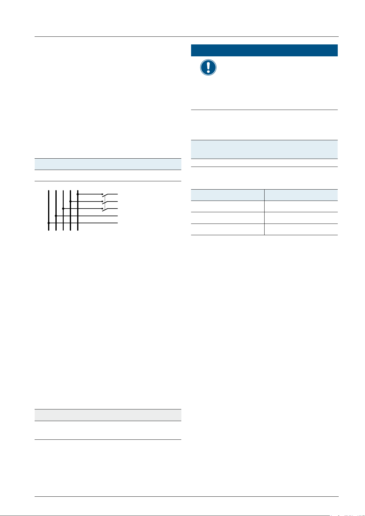
6.7.2 Dry contacts
When the fans fail, Dry contact 1 is closed.
When the inverter feeds into the grid, Dry contact 2 is
closed.
Dry contact 2Dry contact 1
6.7.3 Digital inputs and EPO
The digital inputs can be used to connect an external
ripple control receiver for controlling the active power.
5 6 7 8
1 2 3 4
Pin Design. Short Assigned action
1 V1 - -
2 K0 V1 + K0
3 K1 V1 + K1
4 K2 V1 + K2
5 K3 V1 + K3
6 K4 V1 + K4
7 K5 V1 + K5 Reserved
8 K6 V1 + K6 Reserved
The relay for EPO can be set on the display to “normally open” or “normally closed”, see “8.9 EPO
(External Power Off)”, p. 67.
EPO (Emergency
Power Off)
Set maximum active
power to 0%
Set maximum active
power to 30%
Set maximum active
power to 60%
Set maximum active
power to 100%
Installation and Operation Manual for RPI M50A
47

6 Installation
6.8 Wiring communication port 1
6.8.1 First steps for all cables
Because all communication cables are connected
to the same communication port, you should do the
complete wiring at once.
1. Unscrew and remove the bolting.
3. Pull all cables you want to connect through the
bolting.
2. Unscrew and remove the cover.
6.8.2 Wiring a single inverter for RS 485
Wiring RS 485 depends on whether you want to connect a single or multiple inverters.
1. Connect the two wires to Pin D- and Pin D+.
48
Installation and Operation Manual for RPI M50A

6 Installation
2. Switch on DIP switch 2 to turn on the termination
resistor.
6.8.3 Wiring multiple inverters for RS 485
Wiring RS 485 depends on whether you want to connect a single or multiple inverters.
1. On the rst inverter in the RS485 chain, connect
the cable that comes from the datalogger to the
right Pin DC+ and Pin DC-.
3. On the second inverter, connect the cable that
comes from the rst inverter and the cable that
goes to the next inverter. Repeat these steps for
all other inverters in the RS485 chain, except for
the last inverter.
4. On the last inverter in the RS485 chain, connect
the cable that comes from the datalogger to the
right Pin DC+ and Pin DC-.
2. Connect the cable that goes to the second in-
verter in the RS485 chain to the left Pin DC+ and
Pin DC-.
5. On the last inverter in the RS485 chain, switch on
DIP switch 2 to turn on the termination resistor.
Installation and Operation Manual for RPI M50A
49

6 Installation
6.8.4 Wiring the dry contacts
You can use both dry contacts or only one.
1.
6.8.5 Wiring the digital inputs
You can use one of the digital inputs only. The im-
1.
ages below are examples. The rst image shows
the wiring for using the 60% power limitation
signal (Pin V1 and Pin K3).
6.8.6 Finishing the wiring
Depending on how many cables you connected and
whether it is a single inverter or an inverter in a chain
of multiple inverters, the nal wiring could look like
shown in the following two images.
The second image shows the wiring for using
EPO (Emergency Power Off, Pin V1 and Pin K0).
When you want to use multiple digital inputs, Pin
V1 is used for all of these digital inputs.
1. Screw the cover of the communication port onto
the inverter.
50
Installation and Operation Manual for RPI M50A

6 Installation
WARNING
Dual Supply
Do not work on this equipment until it is isolated from
both mains and on site generation supplies
Isolate on-site Generating Unit(s) at …………………………………………… …….
Isolate mains supply at………………………………………………………
Warning – Only persons authorised by the DNO may remove the main cut out fuse
2. Screw the bolting onto the cover.
6.9 Putting labels on the inverter
After nishing the installation, you have to put all
necessary labels onto the inverter. Check local regulations about which labels are needed. See some
samples below.
Warning
Two sources of voltage present
- distribution network
- photovoltaic panels
Isolate both sources before
carrying out any work
Installation and Operation Manual for RPI M50A
51

7. Commissioning
Français
Select language
CHINA 2013
CHINA MV
FRA-Is 50HZ
YES / NO
Are you sure to
E-actuelle: 0kWh
Etat: On Grid
10.Sep 2014 15:32
7. Commissioning
The inverter must be correctly installed, see “6. Installation”, p. 37.
For information on how the display is operated, see “4.3 Display, buttons, status LEDs”, p. 12.
OFF ON
To execute commissioning, the inverter needs to be powered either by AC
(the grid) or DC (the solar modules).
After powering up the inverter for the fi rst time, the Select language dialog
DISCONN AC/DC
➔
English
Deutsch
CZECH
ENGLAND
is shown.
1. Use the buttons and to select language English.
To confi rm your selection, press the button
ENT
.
2. Use the buttons and to select your country or grid type.
To confi rm your selection, press the button
ENT
.
set country:
United Kingdom
Puissance: 0W
► Check chapter “8. Settings”, p. 53 whether you need to adjust addtional set-
tings.
3. If the selected country is correct, use the buttons and to
select the entry YES.
To confi rm your selection, press the button
If you want to change your selection, press the button
→ The inverter starts a self-test which takes approximately 2 min-
utes. A countdown shows the remaining time on the display.
The basic setup is fi nished. The standard menu is shown.
þ
ENT
.
.
ESC
52
Installation and Operation Manual for RPI M50A

8 Settings
8. Settings
8.1 Overview
8.2 Current grid settings (inverter information) 54
8.3 Display language 55
8.4 Date and time 56
8.5 Baud rate for RS485 57
8.6 Inverter ID 58
8.7 Insulation mode and insulation resistance 59
8.8 Grid settings 61
8.9 EPO (External Power Off) 67
8.10 AC Connection type 68
8.11 Max. Power (Maximum feed-in power) 69
8.12 Power limitation 70
8.13 Power versus frequency 72
8.14 Constant cos phi 74
8.15 Cos phi (P) 76
8.16 Constant Q 78
8.17 Q (V) - Apparent power versus voltage 80
8.18 FRT (Fault Ride Through) 83
Installation and Operation Manual for RPI M50A
Installation and Operation Manual for RPI M50A
53
53

8 Settings
E-Today: 0kWh
Power: 0W
Status: On Grid
10.Sep 2014 15:32
Inverter Info.
8.2 Current grid settings (inverter information)
Overview
With this function you can see the current settings of the solar inverter.
Accessing the menu
Main menu > Inverter info.
1. When the default information is displayed, press any button to open the
Meter
Energy Log
Event Log
main menu. Otherwise, repeatedly press the button
menu is displayed.
2. Use the buttons and to select Inverter info.
To con rm your selection, press the button
ENT
.
3. Use the buttons and to scroll through the list.
4. To leave the menu, press the button
ESC
.
until the main
ESC
54
54
Installation and Operation Manual for RPI M50A
Installation and Operation Manual for RPI M50A

8.3 Display language
E-Today: 0kWh
Status: On Grid
Inverter Info.
Active/Reactive Pwr
FRT
Italiano
Overview
With this function you can set the language used in the display.
Accessing the menu
Main menu > General settings > Language
8 Settings
10.Sep 2014 15:32
Power: 0W
General Settings
Install Settings
Language
Date & Time
Baud rate
English
Deutsch
Français
1. When the default information is displayed, press any button to open the
main menu. Otherwise, repeatedly press the button
menu is displayed.
until the main
ESC
2. Use the buttons and to select General Settings.
To con rm your selection, press the button
ENT
.
3. Use the buttons and to select Language.
To con rm your selection, press the button
ENT
.
4. Use the buttons and to select a language.
To con rm your selection, press the button
ENT
.
Con gurable Parameters
Parameter Description Value range
Language
The language used in the display. –
Installation and Operation Manual for RPI M50A
Installation and Operation Manual for RPI M50A
55
55

8 Settings
E-Today: 0kWh
Power: 0W
Status: On Grid
10.Sep 2014 15:32
Inverter Info.
General Settings
Active/Reactive Pwr
FRT
Language
8.4 Date and time
Overview
With this function you can set date and time.
► For a precise calculation of the statistics in the inverter itself and in a monitoring system, date
and time have to be correct.
Accessing the menu
Main menu > General settings > Date & Time
1. When the default information is displayed, press any button to open the
Install Settings
Date & Time
Baud rate
10.Sep 2014 14:55
main menu. Otherwise, repeatedly press the button
menu is displayed.
until the main
ESC
2. Use the buttons and to select General Settings.
To con rm your selection, press the button
ENT
.
3. Use the buttons and to select Date & time.
To con rm your selection, press the button
ENT
.
4. Use the buttons and to change the currently marked (under-
lined) value.
When nished, press the button
→ The marking moves to the next value.
ENT
.
Con gurable Parameters
Parameter Description Value range
-
56
56
Date and time –
Installation and Operation Manual for RPI M50A
Installation and Operation Manual for RPI M50A

8.5 Baud rate for RS485
E-Today: 0kWh
Status: On Grid
10.Sep 2014 15:32
Inverter Info.
General Settings
Active/Reactive Pwr
FRT
Language
9600
Overview
With this function you can set the baud rate for the RS485 connection.
► If you connect multiple inverters via RS485, set the same baud rate on each inverter.
Accessing the menu
Main menu > General settings > Baud rate
1. When the default information is displayed, press any button to open the
8 Settings
Power: 0W
Install Settings
Date & Time
Baud rate
19200
38400
Con gurable Parameters
main menu. Otherwise, repeatedly press the button
menu is displayed.
ESC
2. Use the buttons and to select General Settings.
To con rm your selection, press the button
ENT
.
3. Use the buttons and to select Baud rate.
To con rm your selection, press the button
ENT
.
4. Use the buttons and to select a baud rate.
To con rm your selection, press the button
ENT
.
until the main
Parameter Description Value range
Baud rate
Installation and Operation Manual for RPI M50A
Installation and Operation Manual for RPI M50A
Sets the baud rate for the RS485
connection.
9600 | 19200 | 38400
57
57

8 Settings
E-Today: 0kWh
Power: 0W
Status: On Grid
10.Sep 2014 15:32
Inverter Info.
Active/Reactive Pwr
FRT
Grid Settings
Inverter ID: 001
8.6 Inverter ID
Overview
With this function you can set an ID for the inverter. The inverter ID is used to identify the inverter in a RS485
connection. The inverter ID is also used in monitoring systems.
► Set a different inverter ID for each inverter in the PV plant. Otherwise, the inverters cannot be
correctly identi ed.
► On the last inverter in the RS485 connection, switch on the RS485 termination resistor. For a
description, see “6.7 Connecting communication port I (optional)”, p. 45.
Accessing the menu
Main menu > Install Settings > Inverter ID
1. When the default information is displayed, press any button to open the
General Settings
Install Settings
Insulation
Country
Setting ID:
ID=001
main menu. Otherwise, repeatedly press the button
until the main
ESC
menu is displayed.
2. Use the buttons and to select Install Settings.
To con rm your selection, press the button
ENT
.
3. The menu is protected by password 5555. Use the buttons and
to set each digit.
To con rm a digit, press the button
ENT
.
4. Use the buttons and to select Inverter ID. The currently set
inverter ID is displayed behind the menu entry.
To con rm your selection, press the button
ENT
.
5. Use the buttons and to set the inverter ID.
To con rm your setting, press the button
ENT
.
Con gurable Parameters
Parameter Description Value range
Setting ID
58
58
Sets the inverter ID that is needed
to identify the inverter when a PV
plant contains multiple inverters.
001 .. 254
Installation and Operation Manual for RPI M50A
Installation and Operation Manual for RPI M50A

8.7 Insulation mode and insulation resistance
E-Today: 0kWh
Status: On Grid
Inverter Info.
Active/Reactive Pwr
FRT
Grid Settings
Inverter ID: 001
Resistance: 1200 kΩ
OFF
Resistance: 1100 kΩ
Mode: ON
150kΩ
Description
With this function you can set up the mode of insulation and the insulation resistance.
Accessing the menu
Main menu > Install Settings > Insulation
8 Settings
10.Sep 2014 15:32
Power: 0W
General Settings
Install Settings
Insulation
Country
Mode: ON
1. When the default information is displayed, press any button to open the
main menu. Otherwise, repeatedly press the button
menu is displayed.
until the main
ESC
2. Use the buttons and to select Install Settings.
To con rm your selection, press the button
ENT
.
3. The menu is protected by password 5555. Use the buttons and
to set each digit.
To con rm a digit, press the button
ENT
.
4. Use the buttons and to select Insulation.
To con rm your selection, press the button
ENT
.
5. Use the buttons and to select Mode. The currently set mode
ON
Plus grounded
Minus grounded
250kΩ
1100kΩ
Installation and Operation Manual for RPI M50A
Installation and Operation Manual for RPI M50A
of insulation is displayed behind the menu entry.
To con rm your selection, press the button
ENT
.
6. Use the buttons and to select a type of insulation.
To con rm your selection, press the button
ENT
.
7. Use the buttons and to select Resistance. The currently set
value for the insulation resistance is displayed behind the menu entry.
To con rm your selection, press the button
ENT
.
8. Use the buttons and to select a value for the insulation resis-
tance.
To con rm your selection, press the button
ENT
.
Do not change this setting without prior
consultation with Delta Solar Support.
59
59

8 Settings
Congurable Parameters
Parameter Description Value range
Mode
Resistance
Mode of insulation ON
Plus grounded
Minus grounded
OFF
Default: ON
Insulation resistance 150 kΩ | 250 kΩ | 1100 kΩ
Default: 1100 kΩ
60
60
Do not change this setting without prior
consultation with Delta Solar Support.
Installation and Operation Manual for RPI M50A
Installation and Operation Manual for RPI M50A

8 Settings
E-Today: 0kWh
Status: On Grid
10.Sep 2014 15:32
Inverter Info.
General Settings
Active/Reactive Pwr
FRT
Grid Settings
Inverter ID: 001
8.8 Grid settings
8.8.1 Overview
This function is factory-set according to the regulation of each country. The inverter is certi ed
with these settings. The settings should not be changed, unless it is really necessary. Please
contact Delta Support when you want to change these settings.
This function is protected by a special password. To get the password, please call the Delta Sup-
port hotline in your country. You can nd the telephone number on the last page of this document.
To adjust several parameters for the currently selected country/grid settings.
The grid settings section consists of the following subsections:
● Voltage protection (How does the inverter behave in case of overvoltages or undervoltages.)
● Frequency protection (How does the inverter behave in case of overfrequencies or underfrequencies.)
● Reconnection time (The delay time the inverter will wait before it reconnects to the grid after a fault.)
● P Ramp up (Feed-in behavior of the inverter when it reconnects to the grid after a fault.)
8.8.2 Voltage protection
Overview
With this function you can de ne how the inverter behaves in case of a grid overvoltage and a grid undervolt-
age.
Accessing the menu
Main menu > Install Settings > Grid settings > Voltage Protection
1. When the default information is displayed, press any button to open the
Power: 0W
main menu. Otherwise, repeatedly press the button
menu is displayed.
until the main
ESC
2. Use the buttons and to select Install Settings.
Install Settings
To con rm your selection, press the button
ENT
.
3. Type in the password you received from Delta Support. Use the buttons
and to set each digit.
Insulation
Country
Installation and Operation Manual for RPI M50A
Installation and Operation Manual for RPI M50A
To con rm a digit, press the button
ENT
.
4. Use the buttons and to select Grid settings.
To con rm your selection, press the button
ENT
.
Do not change this setting without prior
consultation with Delta Solar Support.
61
61

8 Settings
Reconnect T: 600s
P Ramp up: 6000%/m
Voltage Protection
High On: 259.0V
High Off T: 0.3s
Low Off: 104.0V
High Off: 276.0V
Freq. Protection
5. Use the buttons and to select Voltage protection.
To con rm your selection, press the button
ENT
.
6. If you need to change a parameter, use the buttons and to
select the parameter.
Con gurable Parameters
Parameter Description
High Off
High On
High Off T
Low Off
Low On
Low Off T
Voltage High Off
Voltage High On
Disconnection time for Voltage High Off
Voltage Low Off
Voltage Low On
Disconnection time for Voltage Low Off
7. Press the button
to start editing the parameter value.
ENT
8. Use the buttons and to change the parameter value.
To con rm your setting, press the button
cancel the action.
or press the button
ENT
ESC
9. Repeat steps 6 to 8 for the other parameters if you need to change
them.
to
Hi Off Slow
Hi On Slow
Hi Off Slow T
Lo Off Slow
Lo On Slow
Lo Off Slow T
Table 8.1.: Con gurable parameters for Grid settings > Voltage Protection
62
62
Voltage High Off Slow
Voltage High On Slow
Disconnection time for Voltage High Off Slow
Voltage Low Off Slow
Voltage Low On Slow
Disconnection time for Voltage Low Off Slow
Do not change this setting without prior
consultation with Delta Solar Support.
Installation and Operation Manual for RPI M50A
Installation and Operation Manual for RPI M50A

8 Settings
E-Today: 0kWh
Status: On Grid
10.Sep 2014 15:32
Inverter Info.
General Settings
Active/Reactive Pwr
FRT
Grid Settings
Inverter ID: 001
Reconnect T: 600s
P Ramp up: 6000%/m
Voltage Protection
High On: 50.05Hz
High Off T: 0.1s
Low Off: 47.50Hz
High Off: 51.50Hz
8.8.3 Frequency protection
Overview
With this function you can de ne how the inverter behaves in case of a grid overfrequency and a grid underfre-
quency.
Accessing the menu
Main menu > Install Settings > Grid settings > Freq. Protection
1. When the default information is displayed, press any button to open the
Power: 0W
Install Settings
Insulation
Country
Freq. Protection
main menu. Otherwise, repeatedly press the button
menu is displayed.
until the main
ESC
2. Use the buttons and to select Install Settings.
To con rm your selection, press the button
ENT
.
3. Type in the password you received from Delta Support. Use the buttons
and to set each digit.
To con rm a digit, press the button
ENT
.
4. Use the buttons and to select Grid settings.
To con rm your selection, press the button
ENT
.
5. Use the buttons and to select Freq. Protection.
To con rm your selection, press the button
ENT
.
Installation and Operation Manual for RPI M50A
Installation and Operation Manual for RPI M50A
6. Use the buttons and to select a parameter.
7. To start editing the parameter value, press the button
8. To change the parameter value, use the buttons and .
To con rm your setting, press the button
cancel the action.
or press the button
ENT
9. Repeat steps 6 to 8 for all parameters you want to change.
Do not change this setting without prior
consultation with Delta Solar Support.
ENT
.
to
ESC
63
63

8 Settings
Congurable Parameters
Parameter Description
High Off
High On
High Off T
Low Off
Low On
Low Off T
Hi Off Slow
Hi On Slow
Hi Off Slow T
Lo Off Slow
Lo On Slow
Lo Off Slow T
Table 8.2.: Congurable parameters for Grid settings > Frequency Protection
Frequency High Off
Frequency High On
Disconnection time for Frequency High Off
Frequency Low Off
Frequency Low On
Disconnection time for Frequency Low Off
Frequency High Off Slow
Frequency High On Slow
Disconnection time for Frequency High Off Slow
Frequency Low Off Slow
Frequency Low On Slow
Disconnection time for Frequency Low Off Slow
64
64
Do not change this setting without prior
consultation with Delta Solar Support.
Installation and Operation Manual for RPI M50A
Installation and Operation Manual for RPI M50A

8 Settings
E-Today: 0kWh
Status: On Grid
10.Sep 2014 15:32
Inverter Info.
General Settings
Active/Reactive Pwr
FRT
Grid Settings
Inverter ID: 001
Reconnect T: 600s
P Ramp up: 6000%/m
Voltage Protection
8.8.4 Reconnection time
Overview
With this function you can de ne a reconnection time in case the inverter has disconnected from the grid
because of a grid voltage or grid frequency failure (see “8.8.2 Voltage protection”, p. 61 and “8.8.3 Frequency
protection”, p. 63). When the failure disappears, the inverter will wait for the set reconnection time before it
reconnects to the grid.
Accessing the menu
Main menu > Install Settings > Grid settings > Reconnect T
1. When the default information is displayed, press any button to open the
Power: 0W
Install Settings
Insulation
Country
Freq. Protection
main menu. Otherwise, repeatedly press the button
menu is displayed.
until the main
ESC
2. Use the buttons and to select Install Settings.
To con rm your selection, press the button
ENT
.
3. Type in the password you received from Delta Support. Use the buttons
and to set each digit.
To con rm a digit, press the button
ENT
.
4. Use the buttons and to select Grid settings.
To con rm your selection, press the button
ENT
.
5. Use the buttons and to select Reconnect T.
This subsection consists of only one parameter which can be directly
Con gurable Parameters
Parameter Description
Reconnect T
Installation and Operation Manual for RPI M50A
Installation and Operation Manual for RPI M50A
edited.
6. To start editing the parameter value, press the button
7. To change the parameter value, use the buttons and .
ESC
ENT
.
To con rm your setting, press the button
To cancel the action, press the button
Reconnection time
Do not change this setting without prior
consultation with Delta Solar Support.
ENT
.
65
65

8 Settings
E-Today: 0kWh
Power: 0W
Status: On Grid
10.Sep 2014 15:32
Inverter Info.
General Settings
Active/Reactive Pwr
FRT
Grid Settings
Inverter ID: 001
Reconnect T: 600s
P Ramp up: 6000%/m
Voltage Protection
8.8.5 P Ramp Up
Overview
With this function you can de ne a ramp for the active power in case the inverter has disconnected from the grid
because of a grid voltage or grid frequency failure (see “8.8.2 Voltage protection”, p. 61 and “8.8.3 Frequency
protection”, p. 63). When the failure disappears, the inverter will continuously increase the active power fed
into the grid according to the set ramp.
Accessing the menu
Main menu > Install Settings > Grid settings > P Ramp Up
1. When the default information is displayed, press any button to open the
Install Settings
Insulation
Country
Freq. Protection
main menu. Otherwise, repeatedly press the button
menu is displayed.
until the main
ESC
2. Use the buttons and to select Install Settings.
To con rm your selection, press the button
ENT
.
3. Type in the password you received from Delta Support. Use the buttons
and to set each digit.
To con rm a digit, press the button
ENT
.
4. Use the buttons and to select Grid settings.
To con rm your selection, press the button
ENT
.
5. Use the buttons and to select P Ramp Up.
This subsection consists of only one parameter which can be directly
Con gurable Parameters
Parameter Description
P Ramp up
66
66
edited.
6. To start editing the parameter value, press the button
7. To change the parameter value, use the buttons and .
ESC
ENT
.
To con rm your setting, press the button
To cancel the action, press the button
Do not change this setting without prior
consultation with Delta Solar Support.
Installation and Operation Manual for RPI M50A
Installation and Operation Manual for RPI M50A
ENT
.

8 Settings
E-Today: 0kWh
Status: On Grid
Inverter Info.
Active/Reactive Pwr
FRT
Grid Settings
RCMU: ON
EPO: Normal Close
8.9 EPO (External Power Off)
Overview
With this function you can set the type of contact for the EPO function (normally open or normally closed).
Accessing the menu
Main menu > Install Settings > EPO
10.Sep 2014 15:32
Power: 0W
General Settings
Install Settings
DC Injection
Dry Contact
1. When the default information is displayed, press any button to open the
main menu. Otherwise, repeatedly press the button
menu is displayed.
until the main
ESC
2. Use the buttons and to select Install Settings.
To con rm your selection, press the button
ENT
.
3. The menu is protected by password 5555. Use the buttons and
to set each digit.
To con rm a digit, press the button
ENT
.
4. Use the buttons and to select EPO. The current setting is
displayed behind the menu entry.
5. To start editing the parameter value, press the button
ENT
.
Con gurable Parameters
Parameter Description Value range
EPO
Installation and Operation Manual for RPI M50A
Installation and Operation Manual for RPI M50A
6. To change the parameter value, use the buttons and .
To con rm your selection, press the button
To cancel the action, press the button
Sets the type of contact for the relais (normally
closed or normally open).
ENT
.
ESC
Normal Open | Normal Close
Default setting: Normal Close
67
67

8 Settings
E-Today: 0kWh
Power: 0W
Status: On Grid
10.Sep 2014 15:32
Inverter Info.
Active/Reactive Pwr
FRT
AC Connection: 3P4W
EPO: Normal Close
Anti-islanding: ON
Max. Power: 100%
Return to Factory
8.10 AC Connection type
Overview
With this function you can set the type of AC connection you use to connect the inverter to the grid. The inverter
can be connected to a 3-wire system (3P3W: L1, L2, L3, PE) or a 4-wire system (3P4W: L1, L2, L3, N, PE). The
default setting is 3P4W.
Accessing the menu
Main menu > Install Settings > AC Connection
1. When the default information is displayed, press any button to open the
General Settings
Install Settings
main menu. Otherwise, repeatedly press the button
until the main
ESC
menu is displayed.
2. Use the buttons and to select Install Settings.
To con rm your selection, press the button
ENT
.
3. The menu is protected by password 5555. Use the buttons and
to set each digit.
To con rm a digit, press the button
ENT
.
4. Use the buttons and to select AC Connection. The current
setting is displayed behind the menu entry.
5. To start editing the parameter value, press the button
ENT
.
6. To change the parameter value, use the buttons and .
Con gurable Parameters
Parameter Description Value range
AC Connection
68
68
To con rm your selection, press the button
To cancel the action, press the button
Sets the type of AC connection used to connect the
inverter to the grid.
3P3W: 3-wire system (L1, L2, L3, PE)
3P4W: 4-wire system (L1, L2, L3, N, PE)
.
ENT
.
ESC
3P3W | 3P4W
Installation and Operation Manual for RPI M50A
Installation and Operation Manual for RPI M50A

8.11 Max. Power (Maximum feed-in power)
E-Today: 0kWh
Status: On Grid
10.Sep 2014 15:32
Inverter Info.
General Settings
Active/Reactive Pwr
FRT
AC Connection: 3P4W
EPO: Normal Close
Anti-islanding: ON
Max. Power: 50000VA
Return to Factory
Overview
This function should be set only when requested by country regulations, authorities or your grid
operator.
With this function you can limit the maximum active power to be fed into the grid.
Accessing the menu
Main menu > Install Settings > Max. Power
1. When the default information is displayed, press any button to open the
8 Settings
Power: 0W
Install Settings
main menu. Otherwise, repeatedly press the button
until the main
ESC
menu is displayed.
2. Use the buttons and to select Install Settings.
To con rm your selection, press the button
ENT
.
3. The menu is protected by password 5555. Use the buttons and
to set each digit.
To con rm a digit, press the button
ENT
.
4. Use the buttons and to select Max. Power. The current setting
is displayed behind the menu entry.
5. To start editing the parameter value, press the button
ENT
.
6. To change the parameter value, use the buttons and .
Con gurable Parameters
Parameter Description Value range
Max. Power
Installation and Operation Manual for RPI M50A
Installation and Operation Manual for RPI M50A
To con rm your selection, press the button
To cancel the action, press the button
Limits the maximum power to be fed into the grid.
.
ENT
.
ESC
0 .. 55000 VA
Default: according to the country regulations
69
69

8 Settings
E-Today: 0kWh
Power: 0W
Status: On Grid
10.Sep 2014 15:32
Inverter Info.
General Settings
Active/Reactive Pwr
FRT
Reactive Power Ctrl
Active Power Ctrl
Power vs. Frequency
Power Limit
8.12 Power limitation
Overview
Values have been set based upon country standards. If you modify these values, you will lose
certi cation. Therefore you should set this function only when requested by country regulations,
authorities or your grid operator.
With this function you can limit the active power fed into the grid.
The power limitation set with this function relates to the value set for the Max. Power parameter in the installation settings. For a description of the Max. Power parameter, see “8.11 Max. Power (Maximum feed-in power)”,
p. 69.
Example
You have set the maximum power to 80%.
If you additionally set a power limitation of 70%, the total maximum active power is calculated as
50 kW x 80% x 70% = 28 kW.
Accessing the menu
Main menu > Active/Reactive Pwr > Active Power Ctrl > Power limit
1. When the default information is displayed, press any button to open the
main menu. Otherwise, repeatedly press the button
menu is displayed.
2. Use the buttons and to select Active/Reactive Pwr.
Install Settings
To con rm your selection, press the button
3. The menu is protected by password 5555. Use the buttons and
to set each digit.
To con rm a digit, press the button
4. Use the buttons and to select Active Power Ctrl.
To con rm your selection, press the button
ENT
until the main
ESC
.
ENT
.
.
ENT
P(V)
70
70
5. Use the buttons and to select Power Limit.
To con rm your selection, press the button
ENT
.
Do not change this setting without prior
consultation with Delta Solar Support.
Installation and Operation Manual for RPI M50A
Installation and Operation Manual for RPI M50A

8 Settings
Set Point: 100%
Mode: ON
Set Point: 100%
Mode: ON
6. To change the mode, use the buttons and and press the but-
ton
ENT
.
To switch the function on, select ON and press the button
To switch the function off, select OFF and press the button
you switch the function off, you can ignore the following steps.
7. To set the value for the power limitation, use the buttons and
to select Set Point and press the button
ENT
8. Use the buttons and To change the parameter value.
ESC
ENT
.
To con rm your setting, press the button
To cancel the action, press the button
Con gurable Parameters
Parameter Description Value range
ENT
.
ENT
. When
Mode
Set Point
Switches the function on and off.
The value for the power limitation.
ON | OFF
Default value: OFF
0 .. 100%
Default value: 100%
Installation and Operation Manual for RPI M50A
Installation and Operation Manual for RPI M50A
Do not change this setting without prior
consultation with Delta Solar Support.
71
71

8 Settings
E-Today: 0kWh
Power: 0W
Status: On Grid
10.Sep 2014 15:32
Inverter Info.
General Settings
Active/Reactive Pwr
FRT
Reactive Power Ctrl
Active Power Ctrl
8.13 Power versus frequency
Overview
Values have been set based upon country standards. If you modify these values, you will lose certi-
cation. Therefore you should set this function only when requested by country regulations, authori-
ties or your grid operator.
With this function you can control the active power as a function of the grid frequency.
Default behaviour for Germany LV (VDE-AR-N
Default behavior for grid Germany MV (BDEW)
4105)
P
P
m
Gradient (%/Hz)
f
recovery
F
is automatically calculated according to the following formula:
stop
F
stop
= F
+ (1 / Gradient)
start
= f
start
f
stop
f (Hz)
m
f
recovery
Accessing the menu
Main menu > Active/Reactive Pwr > Active Power Ctrl > Power vs. Frequency
1. When the default information is displayed, press any button to open the
Gradient (%/Hz)
f
start
f
stop
f (Hz)
Install Settings
72
72
main menu. Otherwise, repeatedly press the button
ESC
menu is displayed.
2. Use the buttons and to select Active/Reactive Pwr.
To con rm your selection, press the button
ENT
.
3. The menu is protected by password 5555. Use the buttons and
to set each digit.
To con rm a digit, press the button
ENT
.
4. Use the buttons and to select Active Power Ctrl. The current
setting is displayed behind the menu entry.
Do not change this setting without prior
consultation with Delta Solar Support.
Installation and Operation Manual for RPI M50A
Installation and Operation Manual for RPI M50A
until the main

P(V)
Power vs. Frequency
Power Limit
F Recovery: 50.20Hz
Gradient: 100%
F Start: 50.20Hz
Mode: ON
F Recovery: 50.20Hz
Gradient: 100%
F Start: 50.20Hz
Mode: ON
8 Settings
5. Use the buttons and to select Power vs Frequency. The cur-
rent setting is displayed behind the menu entry.
6. To change the mode, use the buttons and and press the but-
Con gurable Parameters
Parameter Description
ton
To switch the function on, select ON and press the button
To switch the function off, select OFF and press the button
you switch the function off, you can ignore the following steps.
ENT
.
.
ENT
. When
ENT
7. Use the buttons and to select a parameter and press the but-
ton
ENT
.
8. To change the parameter value, use the buttons and .
ESC
ENT
.
To con rm your setting, press the button
To cancel the action, press the button
9. Repeat steps 7 to 8 for all parameters you want to change.
Mode
F Start
F Recovery
Gradient
T Recovery When the grid frequency drops to F Recovery, the inverter will wait for the time
Switches the function on and off.
The grid frequency at which the inverter starts to limit the active power according to
the Gradient parameter.
The grid frequency at which the inverter reconnects to the grid or at which the
inverter feeds-in full power again. The behavior depends on the selected country and
grid.
Adjustment of the active power fed into the grid in percent per Hz when the grid frequency is between F Start and F Stop.
de ned in T Recovery before it returns to normal operating behavior.
Installation and Operation Manual for RPI M50A
Installation and Operation Manual for RPI M50A
Do not change this setting without prior
consultation with Delta Solar Support.
73
73

8 Settings
E-Today: 0kWh
Power: 0W
Status: On Grid
10.Sep 2014 15:32
Inverter Info.
General Settings
Active/Reactive Pwr
FRT
Reactive Power Ctrl
Active Power Ctrl
Q(V)
Cos phi: Ind 1.00
Mode: ON
Cos phi: Ind 1.00
Mode: ON
8.14 Constant cos phi
Overview
With this function you can set a constant cos phi (cos φ).
This function should be set only when requested by country regulations, authorities or your grid
operator.
Accessing the menu
Main menu > Active/Reactive Pwr > Reactive Power Ctrl > Constant cos phi
1. When the default information is displayed, press any button to open the
Install Settings
Constant cos phi
Cos phi (P)
Constant Q
main menu. Otherwise, repeatedly press the button
menu is displayed.
until the main
ESC
2. Use the buttons and to select Active/Reactive Pwr.
To con rm your selection, press the button
ENT
.
3. The menu is protected by password 5555. Use the buttons and
to set each digit.
To con rm a digit, press the button
ENT
.
4. Use the buttons and to select Reactive Power Ctrl. The cur-
rent setting is displayed behind the menu entry.
5. Use the buttons and to select Constant cos phi. The current
setting is displayed behind the menu entry.
74
74
6. To change the mode, use the buttons and to select Mode and
press the button
To switch the function on, select ON and press the button
To switch the function off, select OFF and press the button
you switch the function off, you can ignore the following steps.
ENT
.
7. If you need to change the cos phi (cos φ), use the buttons and
to select Cos phi and press the button
ENT
Do not change this setting without prior
consultation with Delta Solar Support.
Installation and Operation Manual for RPI M50A
Installation and Operation Manual for RPI M50A
ENT
.
ENT
. When

8 Settings
8. To change the parameter value, use the buttons and .
To conrm your setting, press the button
To cancel the action, press the button
Congurable Parameters
Parameter Description Value range
Mode
Cos phi
Switches the function on and off.
Sets up a cos phi so that the inverter can feed reactive power into the grid.
.
ENT
.
ESC
ON | OFF
Default value: OFF
ind 0.8 ... cap 0.8
Do not change this setting without prior
consultation with Delta Solar Support.
Installation and Operation Manual for RPI M50A
Installation and Operation Manual for RPI M50A
75
75
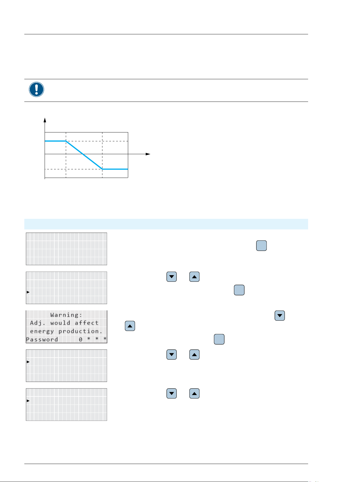
8 Settings
E-Today: 0kWh
Power: 0W
Status: On Grid
10.Sep 2014 15:32
Inverter Info.
Active/Reactive Pwr
FRT
Reactive Power Ctrl
Q(V)
8.15 Cos phi (P)
Overview
Values have been set based upon country standards. If you modify these values, you will lose certi-
cation. Therefore you should set this function only when requested by country regulations, authori-
ties or your grid operator.
With this function you can set the cos phi (cos φ) as a function of the active power.
cos φ
0.8
Q
upper
1.0
Q
lower
0.8
P
lower
Accessing the menu
Main menu > Active/Reactive Pwr > Active Power Ctrl > Cos phi (P)
P
upper
100%
P/P
n
1. When the default information is displayed, press any button to open the
main menu. Otherwise, repeatedly press the button
menu is displayed.
General Settings
2. Use the buttons and to select Active/Reactive Pwr.
Install Settings
To con rm your selection, press the button
3. The menu is protected by password 5555. Use the buttons and
ENT
until the main
ESC
.
Active Power Ctrl
Constant cos phi
Cos phi (P)
Constant Q
76
76
to set each digit.
To con rm a digit, press the button
ENT
.
4. Use the buttons and to select Reactive Power Ctrl. The cur-
rent setting is displayed behind the menu entry.
5. Use the buttons and to select Cos phi (P). The current setting
is displayed behind the menu entry.
Do not change this setting without prior
consultation with Delta Solar Support.
Installation and Operation Manual for RPI M50A
Installation and Operation Manual for RPI M50A

8 Settings
Q lower: Ind 1.00
P lower: 45%
Q upper: Ind 1.00
Mode: ON
Q lower: Ind 1.00
P lower: 45%
Q upper: Ind 1.00
Mode: ON
6. To change the mode, use the buttons and to select Mode and
Con gurable Parameters
Parameter Description
press the button
To switch the function on, select ON and press the button
To switch the function off, select OFF and press the button
you switch the function off, you can ignore the following steps.
ENT
.
.
ENT
. When
ENT
7. If you need to change a parameter, use the buttons and to
select the parameter and press the button
ENT
.
8. To change the parameter value, use the buttons and .
ESC
ENT
.
.
To con rm your setting, press the button
To cancel the action, press the button
9. Repeat steps 7 to 8 for other parameters if you need to change them.
Mode
Q upper
P upper
Q lower
P lower
V lock-in
V lock-out
Switches the function on and off.
Sets up the upper limit for the reactive power which is set as a cos phi (cos φ).
Sets up the upper limit for the active power which is set in per cent of the nominal
power.
Sets up the lower limit for the reactive power which is set as a cos phi (cos φ).
Sets up the lower limit for the active power which is set in per cent of the nominal
power.
The lower limit of the grid voltage range in which the function is active. The parameter is used for Italy only.
The upper limit of the grid voltage range in which the function is active. The parameter is used for Italy only.
Installation and Operation Manual for RPI M50A
Installation and Operation Manual for RPI M50A
Do not change this setting without prior
consultation with Delta Solar Support.
77
77

8 Settings
E-Today: 0kWh
Power: 0W
Status: On Grid
10.Sep 2014 15:32
Inverter Info.
General Settings
Active/Reactive Pwr
FRT
Reactive Power Ctrl
Active Power Ctrl
Q(V)
Constant cos phi
Fix Q: Ind 90%
Mode: ON
Fix Q: Ind 90%
Mode: ON
8.16 Constant Q
Overview
With this function you can set a constant reactive power.
This function should be set only when requested by country regulations, authorities or your grid
operator.
Accessing the menu
Main menu > Active/Reactive Pwr > Active Power Ctrl > Constant Q
1. When the default information is displayed, press any button to open the
Install Settings
Cos phi (P)
Constant Q
main menu. Otherwise, repeatedly press the button
menu is displayed.
until the main
ESC
2. Use the buttons and to select Active/Reactive Pwr.
To con rm your selection, press the button
ENT
.
3. The menu is protected by password 5555. Use the buttons and
to set each digit.
To con rm a digit, press the button
ENT
.
4. Use the buttons and to select Reactive Power Ctrl. The cur-
rent setting is displayed behind the menu entry.
5. Use the buttons and to select Constant Q. The current setting
is displayed behind the menu entry.
78
78
6. To change the mode, use the buttons and to select Mode and
press the button
To switch the function on, select ON and press the button
To switch the function off, select OFF and press the button
you switch the function off, you can ignore the following steps.
ENT
.
7. If you need to change the parameter Fix Q, use the buttons and
to select the parameter and press the button
ENT
Do not change this setting without prior
consultation with Delta Solar Support.
Installation and Operation Manual for RPI M50A
Installation and Operation Manual for RPI M50A
ENT
.
ENT
. When

8 Settings
8. To change the parameter value, use the buttons and .
Congurable Parameters
Parameter Description
Mode
Fix Q
Switches the function on and off.
Sets up a constant reactive power which is set in per cent of the nominal apparent
power S
.
n
ESC
ENT
.
.
To conrm your setting, press the button
To cancel the action, press the button
9. Repeat steps 7 to 8 for other parameters if you need to change them.
Do not change this setting without prior
consultation with Delta Solar Support.
Installation and Operation Manual for RPI M50A
Installation and Operation Manual for RPI M50A
79
79

8 Settings
8.17 Q (V) - Apparent power versus voltage
Overview
Values have been set based upon country standards. If you modify these values, you will lose certication. Therefore you should set this function only when requested by country regulations, authorities or your grid operator.
With this function you can set the apparent power as a function of the grid voltage.
This function is available for medium voltage grids only.
(1) Behavior for Curve A (2) Behavior for Curve B
63%
63%
184.0 V
Q inductiveQ cpacitive
Q
s limit
V
V
1i
2i
Q
V
i limit
V
1s
2s
264.5 V230.0 V
63%
Q
s limit
Q inductiveQ cpacitive
V
V
1i
V
inductive cos φ
63%
184.0 V
2i
Q
V
i limit
V
1s
2s
V
264.5 V230.0 V
Operating behavior for curve A
When the grid voltage increases to the lower voltage limit V1s, the inverter starts to feed-in inductive reactive
power. When you set the parameter T inductive, the inverter will wait for this period time for the grid voltage
falling back to a level below V1s before it starts feeding in inductive reactive power. When the grid voltage con-
tinues to increase, the inductive reactive power will be increased according to the ramp dened by the curve. If
the grid voltage exceeds the upper voltage limit V2s, the inductive active power remains at the level dened in
Qs limit.
When the grid voltage falls to the upper voltage limit V1i, the inverter starts to feed-in inductive reactive power.
When you set the parameter T delay, the inverter will wait for this period time for the grid voltage rising back
to a level above V1i before it starts feeding in inductive reactive power. When the grid voltage continues to fall,
the inductive reactive power will be increased according to the ramp dened by the curve. If the grid voltage
exceeds the upper voltage limit V2i, the inductive active power remains at the level dened in Qi limit.
Do not change this setting without prior
consultation with Delta Solar Support.
Installation and Operation Manual for RPI M50A
80
80
Installation and Operation Manual for RPI M50A

Accessing the menu
E-Today: 0kWh
Status: On Grid
10.Sep 2014 15:32
Inverter Info.
General Settings
Active/Reactive Pwr
FRT
Reactive Power Ctrl
Active Power Ctrl
Q(V)
Qs limit: Ind 44%
V2s: 253.0V
V1s: 248.4V
Mode: OFF
Qs limit: Ind 44%
V2s: 253.0V
V1s: 248.4V
Mode: Curve A
Main menu > Active/Reactive Pwr > Active Power Ctrl > Q (V)
1. When the default information is displayed, press any button to open the
8 Settings
Power: 0W
Install Settings
Constant cos phi
Cos phi (P)
Constant Q
main menu. Otherwise, repeatedly press the button
menu is displayed.
until the main
ESC
2. Use the buttons and to select Active/Reactive Pwr.
To con rm your selection, press the button
ENT
.
3. The menu is protected by password 5555. Use the buttons and
to set each digit.
To con rm a digit, press the button
ENT
.
4. Use the buttons and to select Reactive Power Ctrl. The cur-
rent setting is displayed behind the menu entry.
5. Use the buttons and to select Q (V). The current setting is
displayed behind the menu entry.
6. To change the mode, use the buttons and to select Mode and
press the button
To switch the function on, select a mode and press the button
To switch the function off, select OFF and press the button
you switch the function off, you can ignore the following steps.
ENT
.
.
ENT
. When
ENT
7. If you need to change a parameter, use the buttons and to
select the parameter and press the button
ENT
.
8. To change the parameter value, use the buttons and .
ESC
ENT
.
.
To con rm your setting, press the button
To cancel the action, press the button
9. Repeat steps 7 to 8 for other parameters if you need to change them.
Installation and Operation Manual for RPI M50A
Installation and Operation Manual for RPI M50A
Do not change this setting without prior
consultation with Delta Solar Support.
81
81

8 Settings
Congurable Parameters
Parameter Description
Mode OFF Switches the function on and off.
Curve A
Curve B
V1s
V2s
Qs limit
V1i
V2i
Qi limit
T delay
P lock-in
P lock-out
The lower voltage limit for feeding-in capacitive reactive power.
The upper voltage limit for feeding-in capacitive reactive power.
The limit for the inductive apparent power. The value is set in per cent of the rated
apparent power S
The upper voltage limit for feeding-in inductive reactive power.
The upper voltage limit for feeding-in inductive reactive power.
The limit for the inductive apparent power. The value is set in per cent of the rated
apparent power S
Internal parameter
The lower limit of the active power range within which the function is active. The
parameter is given in percent of the nominal power. Used for Italy only.
The upper limit of the active power range within which the function is active. The
parameter is given in percent of the nominal power. Used for Italy only.
. This value is with parameter V2s.
n
. This value is with parameter V2s.
n
82
82
Do not change this setting without prior
consultation with Delta Solar Support.
Installation and Operation Manual for RPI M50A
Installation and Operation Manual for RPI M50A

8 Settings
E-Today: 0kWh
Status: On Grid
10.Sep 2014 15:32
Inverter Info.
Active/Reactive Pwr
FRT
8.18 FRT (Fault Ride Through)
Overview
Values have been set based upon country standards. If you modify these values, you will lose certi-
cation. Therefore you should set this function only when requested by country regulations, authori-
ties or your grid operator.
With this function you can set the operation behavior of the inverter for FRT (Fault Ride Through).
Fig. 8.28: Operation behavior for FRT (Fault Ride Through)
t1 : The point in time when the fault occurs.
Accessing the menu
Main menu > FRT
1. When the default information is displayed, press any button to open the
main menu. Otherwise, repeatedly press the button
Power: 0W
General Settings
menu is displayed.
2. Use the buttons and to select FRT.
Install Settings
To con rm your selection, press the button
3. The menu is protected by password 5555. Use the buttons and
to set each digit.
ENT
until the main
ESC
.
Installation and Operation Manual for RPI M50A
Installation and Operation Manual for RPI M50A
To con rm a digit, press the button
ENT
.
Do not change this setting without prior
consultation with Delta Solar Support.
83
83

8 Settings
t1: 0.30s
Vdrop: 0%
Dead band: -10%
Mode: ON
t1: 0.30s
Vdrop: 0%
Dead band: -10%
Mode: ON
4. To change the mode, use the buttons and to select Mode and
Con gurable Parameters
press the button
To switch the function on, select Mode = ON and press the button
To switch the function off, select select Mode = OFF and press the but-
ton
steps.
. When you switch the function off, you can ignore the following
ENT
ENT
.
5. If you need to change a parameter, use the buttons and to
select the parameter and press the button
ENT
6. To change the parameter value, use the buttons and .
ESC
ENT
.
To con rm your setting, press the button
To cancel the action, press the button
7. Repeat steps 5 to 6 for all parameters you need to change.
ENT
.
Parameter Description
Mode
Dead band
Vdrop
t1
U1
t3
K factor
Switches the function on and off.
Dead band
Drop voltage
Time t1
Voltage U1
Time t3
K factor
84
84
Do not change this setting without prior
consultation with Delta Solar Support.
Installation and Operation Manual for RPI M50A
Installation and Operation Manual for RPI M50A

9 Measurements and statistics
E-Today: 0kWh
Status: On Grid
Inverter Info.
Meter
P 0 0 0 W
I 0 0 0 A
V 0 0 0 V
AC L1 L2 L3
E-Today: 0 kWh
Frequency: 0 Hz
AC
P 0 0 W
I 0 0 A
V 0 0 V
DC DC1 DC2
9. Measurements and statistics
The inverter provides several measurements and statistics about the operating behavior and events that can
have an infl uence on the operating behavior.
The following types of measurements and statistics are available:
Type of information Description
Meter Current data of many parameters.
Energy log Energy information for total lifetime.
Event log A list of important events like failures, parameter changes etc. with date and time.
Inverter information Basic information like general settings, software versions etc.
9.1 Meter
Description
In this menu you fi nd the current data of several parameters in real time. The meter statistics consist of three
pages. The information can only be read and not edited.
Accessing the Menu
Main menu > Meter
10.Sep 2014 15:32
Power: 0W
Energy Log
Event Log
Power: 0 W
1. When the default information is displayed, press any button to open the
main menu. Otherwise, repeatedly press the button
menu is displayed.
until the main
ESC
2. Use the buttons and to select Meter.
To confi rm your selection, press the button
ENT
.
3. Use the buttons and to scroll through the meter statistics.
Installation and Operation Manual for RPI M50A
Installation and Operation Manual for RPI M50A
4. To close the meter statistics, press the button
ESC
.
85
85

9 Measurements and statistics
Displayed Parameters
Parameter Description
Page 1 AC side
For the AC side in total is displayed:
Power
Frequency
E-Today
Currently produced active power, in W.
Current grid frequency, in Hz.
Total energy produced on this day, in kWh.
Page 2 AC side
For each phase (L1, L2, L3) is displayed:
V
I
P
Voltage, in V
Current, in A
Active Power, in W
Page 3 DC side
For each DC input is displayed:
V
I
P
Voltage, in V
Current, in A
Power, in W
86
86
Installation and Operation Manual for RPI M50A
Installation and Operation Manual for RPI M50A

9 Measurements and statistics
E-Today: 0kWh
Status: On Grid
Inverter Info.
Meter
Life energy: 0kWh
Energy log
9.2 Energy log
Description
In these statistics you fi nd several values for the total lifetime of the solar inverter.
Accessing the Menu
Main menu > Energy log
10.Sep 2014 15:32
Power: 0W
Energy Log
Event Log
Runtime: 0h
Displayed Parameters
Parameter Description
Life energy
Total amount of energy produced by the solar inverter, in kWh.
1. When the default information is displayed, press any button to open the
main menu. Otherwise, repeatedly press the button
menu is displayed.
until the main
ESC
2. Use the buttons and to select Energy log.
ESC
ENT
.
.
To confi rm your selection, press the button
3. To close the energy log, press the button
Runtime
Installation and Operation Manual for RPI M50A
Installation and Operation Manual for RPI M50A
The total time that the inverter was in operation.
87
87

9 Measurements and statistics
E-Today: 0kWh
Power: 0W
Status: On Grid
10.Sep 2014 15:32
Inverter Info.
Meter
9.3 Event log
Description
The event log is a list of important events that happened during operation.
Accessing the Menu
Main menu > Event log
1. When the default information is displayed, press any button to open the
Energy Log
Event Log
main menu. Otherwise, repeatedly press the button
menu is displayed.
until the main
ESC
2. Use the buttons and to select Event log.
To confi rm your selection, press the button
ENT
.
3. Use the buttons and to scroll through the event log.
88
88
Installation and Operation Manual for RPI M50A
Installation and Operation Manual for RPI M50A

9.4 Inverter information
E-Today: 0kWh
Status: On Grid
Inverter Info.
Meter
Inverter Info.
Meter
Description
In this section you fi nd general information about the inverter.
Accessing the Menu
Main menu > Event log
9 Measurements and statistics
10.Sep 2014 15:32
Power: 0W
Energy Log
Event Log
Energy Log
Event Log
Displayed Parameters
Parameter Description
S/N
DSP, Red, Comm, Wifi
Serial number.
The software versions of the various controllers.
1. When the default information is displayed, press any button to open the
main menu. Otherwise, repeatedly press the button
menu is displayed.
until the main
ESC
2. Use the buttons and to select Inverter Info.
To confi rm your selection, press the button
ENT
.
3. Use the buttons and to scroll through the inverter information.
ID
Country
Insulation
Baud rate
Install
AC connection
Pmax
Installation and Operation Manual for RPI M50A
Installation and Operation Manual for RPI M50A
The currently set inverter ID for RS485. For a description how to change the inverter
ID, see “8.6 Inverter ID”, p. 58.
The currently set country/grid.
The currently set insulation resistance in kΩ. For a description how to change the
insulation settings, see “8.7 Insulation mode and insulation resistance”, p. 59.
The currently set baud rate for RS485. For a description how to change the baud rate,
see “8.5 Baud rate for RS485”, p. 57.
The date of installation.
The currently chosen type of AC connection. For a description how to set a different
type of AC connection, see “8.11 AC Connection type”, p. 68.
The currently set maximum active power that the inverter feeds into the grid. For a
description how to change the maximum active power, see “8.12 Max. Power (Maxi-
mum feed-in power)”, p. 69.
89
89

10. Error messages and trouble shooting
10. Error messages and trouble shooting
10.1 Errors
Message Possible cause Solution
AC Freq Low ● Actual utility frequency is under the
UFR (under frequency recognition)
setting.
● Incorrect country or grid setting. ● Check country and grid setting.
● Detection circuit malfunction. ● Check the detection circuit inside
AC Freq High ● Actual utility frequency is over the
OFR (over frequency recognition)
setting.
● Incorrect country setting. ● Check country setting.
● Detection circuit malfunction. ● Check the detection circuit inside
AC Volt High ● Actual utility voltage is over the OVR
(over voltage recognition) setting.
● Utility voltage is over the Slow OVR
setting during operation.
● Incorrect country or grid setting. ● Check country and grid setting.
● Detection circuit malfunction. ● Check the detection circuit inside
● Check the utility frequency on solar
inverter terminal.
solar inverter.
● Check the utility frequency on solar
inverter terminal.
solar inverter.
● Check the utility voltage on solar
inverter terminal.
● Check the utility voltage on solar
inverter terminal.
solar inverter.
AC Volt Low ● Actual utility voltage is under the UVR
(under voltage recognition) setting.
● Incorrect country or grid setting. ● Check country and grid setting.
● Wrong connections in AC plug. ● Check the connection in AC plug.
● Detection circuit malfunction. ● Check the detection circuit inside
Grid Quality ● Non-linear load in grid and near to
inverter.
HW Connect Fail ● Wrong connection in AC plug. ● Check the AC connection.
● Detection circuit malfunction. ● Check the detection circuit inside
Insulation ● PV array insulation fault. ● Check the insulation of Solar inputs.
● Large PV array capacitance between
Plus to Ground or Minus to Ground or
both.
● Detection circuit malfunction. ● Check the detection circuit inside
● Check the utility voltage connection to
solar inverter terminal.
solar inverter.
● Grid connection of inverter needs to
be far away from non-linear load if
necessary.
solar inverter.
● Check the capacitance, dry PV panel
if necessary.
solar inverter.
No Grid ● AC breaker is OFF. ● Switch on AC breaker.
● Disconnect in AC plug. ● Check the connection in AC plug and
make sure it connects to inverter.
90
Installation and Operation Manual for RPI M50A

10. Error messages and trouble shooting
Message Possible cause Solution
Solar1 High ● Actual Solar1 voltage is over
1000 V
● Detection circuit malfunction. ● Check the detection circuit inside
Solar2 High ● Actual Solar2 voltage is over
1000 V
● Detection circuit malfunction. ● Check the detection circuit inside
DC
DC
.
.
● Modify the solar array setting, and
make the Voc less than 1000 VDC.
solar inverter.
● Modify the solar array setting, and
make VDC less than 1000 VDC.
solar inverter.
10.2 Warnings
Message Possible cause Solution
Solar1 Low ● Actual Solar1 voltage is under the
limit.
● Some devices were damaged inside
solar inverter if the actual Solar1 voltage is close to “0”.
● Detection circuit malfunction. ● Check the detection circuit inside
● Check the Solar1 voltage connection
to solar inverter terminal.
● Check all switching devices in boost1.
solar inverter.
EN
Solar2 Low ● Actual Solar2 voltage is under the
limit.
● Some devices were damaged inside
solar inverter if the actual Solar2 voltage is close to “0”.
● Detection circuit malfunction. ● Check the detection circuit inside
● Check the Solar2 voltage connection
to solar inverter terminal.
● Check all switching devices in boost2.
solar inverter.
10.3 Faults
Message Possible cause Solution
AC Current High ● Surge occurs during operation. ● Call Delta Support.
● Driver for inverter stage is defective. ● Check the driver circuit in inverter
stage.
● Switching device is defective. ● Check all switching devices in inverter
stage.
● Detection circuit malfunction. ● Check the detection circuit inside
solar inverter.
Bus Unbalance ● Not totally independent or parallel
between inputs.
● Check the inputs connections.
Installation and Operation Manual for RPI M50A
● PV array short to ground. ● Check the PV array insulation.
● Driver for boost is defective or discon-
nected.
● Detection circuit malfunction. ● Check the detection circuit inside
● Check the driver circuit for boost
inside solar inverter.
solar inverter.
91

10. Error messages and trouble shooting
Message Possible cause Solution
DC Current High ● Switching device in boost is defective. ● Check all switching device in boost.
● Driver for boost is defective. ● Check the driver curcuit for boost
inside the solar inverter.
● Input current detection circuit mal-
● Check input current detection circuit.
function.
Ground Current ● PV array insulation fault. ● Check the insulation of DC inputs.
● Large PV array capacitance between
Plus to Ground or Minus to Ground.
● Check the capacitance (+ <-> GND
& - <->GND), must < 2.5 µF. Install a
external transformer if necessary.
● Either side of boost driver or boost
● Check boost driver & boost choke.
choke malfunction.
● Detection circuit malfunction. ● Check the detection circuit inside
solar inverter.
HW AC OCR ● Large grid harmonics. ● Check the utility waveform. Grid con-
nection of inverter needs to be far
away from non-linear load if necessary.
● Switching device is defective. ● Check all switching devices in inverter
stage.
● Detection circuit malfunction. ● Check the detection circuit inside the
solar inverter.
HW Bus OVR ● Driver for boost is defective. ● Check the driver circuit for boost
inside solar inverter.
● Voc of PV array is > 1000 V
. ● Modify the solar array setting, and
DC
make VDC less than 1000 VDC.
● Surge occurs during operation. ● Call Delta Support.
● Detection circuit malfunction. ● Check the detection circuit inside
solar inverter.
HW COMM1 ● DSP is idling. ● Check reset and crystal in DSP.
● The communication connection is
disconnected.
● The communication circuit malfunc-
● Check the connection between DSP
and COMM.
● Check the communication circuit.
tion.
HW COMM2 ● Red. CPU is idling. ● Check reset and crystal in Red. CPU.
● The communication connection is
disconnected.
HW Connect Fail ● Power line is disconnected inside
solar inverter.
● Check the connection between Red.
CPU and DSP.
● Check the power lines inside solar
inverter.
● Current feedback circuit is defective. ● Check the current feedback circuit
inside solar inverter.
92
Installation and Operation Manual for RPI M50A

10. Error messages and trouble shooting
Message Possible cause Solution
HW CT A Fail ● Test current loop is broken. ● Check the connection of CNP4 to
CNM4.
● CTP3 is defective. ● Replay CTP3 with new one.
● Detection circuit malfunction. ● Check the detection circuit inside the
solar inverter.
HW CT B Fail ● Test current loop is broken. ● Check the connection of CNP4 to
CNM4.
● CTP4 is defective. ● Replace CTP4 with new one.
● Detection circuit malfunction. ● Check the detection circuit inside the
solar inverter.
HW CT C Fail ● Test current loop is broken. ● Check the connection of CNP4 to
CNM4.
● CTP5 is defective. ● Replace CTP5 with new one.
● Detection circuit malfunction. ● Check the detection circuit inside the
solar inverter.
HW DC Injection ● Utility waveform is abnormal. ● Check the utility waveform. Grid con-
nection of inverter needs to be far
away from non-linear load if necessary.
● Detection circuit malfunction. ● Check the detection circuit inside
solar inverter.
EN
HW DSP ADC1
HW DSP ADC2
HW DSP ADC3
● Insufcient input power. ● Check the input voltage, must >
DC
.
150 V
● Auxiliary power circuitry malfunction. ● Check the auxiliary circuitry inside the
solar inverter.
● Detection circuit malfunction. ● Check the detection circuit inside the
solar inverter.
Installation and Operation Manual for RPI M50A
93

10. Error messages and trouble shooting
Message Possible cause Solution
HW Efciency ● The calibration is incorrect. ● Check the accuracy of current and
power.
● Current feedback circuit is defective. ● Check the current feedback circuit
inside solar inverter.
HW NTC1 Fail
HW NTC2 Fail
HW NTC3 Fail
HW NTC4 Fail
HW Red ADC1
HW Red ADC2
● Ambient temperature > 90 °C or < -30
°C.
● Check the installation ambient and
environment.
● Detection circuit malfunction. ● Check the detection circuit inside
solar inverter.
● Insufcient input power. ● Check the input voltage, must >
DC
.
150 V
● Auxiliary power circuitry malfunction. ● Check the auxiliary circuitry inside the
solar inverter.
● Detection circuit malfunction. ● Check the detection circuit inside the
solar inverter.
HW ZC Fail ● The detection circuit for synchronal
signal malfunction.
● Check the detection circuit for syn-
chronal signal inside the solar inverter.
RCMU Fail ● RCMU is disconnected. ● Check the RCMU connection inside
solar inverter.
● Detection circuit malfunction. ● Check the detection circuit inside
solar inverter.
Relay Test Open ● One or more relays are abnormal. ● Replace the defective relay(s).
● The driver circuit for the relay mal-
function.
● Check the driver circuit inside solar
inverter.
● The detection accuracy is not correct
for V
grid
and V
out
.
● Check the V
tection accuracy.
grid
and V
voltage de-
out
Relay Test Short ● One or more relays are sticking. ● Replace the defective relay(s).
● The driver circuit for the relay mal-
function.
Temperature High ● The ambient is > 60 °C (the installa-
tion is abnormal).
● Check the driver circuit inside solar
inverter.
● Check the installation ambient and
environment.
● Detection circuit malfunction. ● Check the detection circuit inside
solar inverter.
Temperature Low ● Ambient temperature is < -30 °C. ● Check the installation ambient and
environment.
● Detection circuit malfunction. ● Check the detection circuit inside
solar inverter.
94
Installation and Operation Manual for RPI M50A

11. Maintenance
DANGER
Risk of death by electrocution
Potentially fatal voltage is applied to
the solar inverter during operation. This
potentially fatal voltage is still present
for 10 seconds after all power sources
have been disconnected.
► Never open the solar inverter.
► Always disconnect the solar inverter
from power before installation, open
the AC/DC isolating switch and
make sure neither can be accidentally reconnected.
► Wait at least 10 seconds until the
capacitors have discharged.
WARNING
High electrocution
When you remove the cover from the
fuse section, protection degree is no
longer IP65.
► Remove the cover only when it is
really necessary.
► Do not remove the cover when it is
raining and the inverter is wet.
► Close the cover tightly after work.
11 Maintenance
In order to ensure the normal operation of the solar
inverter, please check it regularly at least once every
6 months. Check that all the terminals, screws, cables
are securely in place. If there are any damaged parts,
please contact a qualied technician to repair it or
to replace it with a new spare part. To ensure that
no foreign contaminants enter the warm air outlets,
please have them cleaned every 6 months by quali-
ed technicians.
11.1 Regular maintenance
Every 6 months the following checkings should be
done.
● Check string fuses. Measure the current by using
a current transducer.
● Check fans.
● Check air lters.
Installation and Operation Manual for RPI M50A
95

11 Maintenance
11.2 Replacing the fans
1. Loosen the 4 screws of the fan section.
2. Pull out the fan section.
4. Plug the ve connectors with the wires into the
fan section. The order of the connectors does not
matter.
5. Put the new fan section into the inverter housing.
3. Pull out the ve connectors with the wires.
6. Fasten the 4 screws of the fan section.
96
Installation and Operation Manual for RPI M50A

11 Maintenance
11.3 Cleaning the fans
CAUTION
Crushing hazard
The fans contain moving parts, on
which you can hurt your ngers.
► Never use your ngers to remove
debris from the fans.
► Never use sharp tools as these can
damage the fans.
► Use an air blower that blows dry air
to clean the fans.
1. Loosen the 4 screws of the fan section.
4. Plug the ve connectors with the wires into the
fan section. The order of the connectors does not
matter.
5. Put the fan section into the inverter housing.
2. Pull out the fan section.
3. Pull out the ve connectors with the wires.
6. Fasten the 4 screws of the fan section.
Installation and Operation Manual for RPI M50A
97

11 Maintenance
11.4 Cleaning the air fi lters
The screws of the lter section are very small
and can easily fall down. You should use a
magnetic screw driver.
The inverter has two air lters, one on the upper left
side and one on the upper right side.
1. Remove the 4 screws from each lter section.
2. Pull out the air lter section.
5. Fasten each air lter section with the four screws.
3. Clean the air lter with an air blower or a cloth.
4. Put the air lter section into the inverter housing.
98
Installation and Operation Manual for RPI M50A

11.5 Replacing surge protection devices (SPD) on the DC side
Use only the SPDs mentioned in the table
below for replacement.
Delta reserves the right to deny warranty if
another SPD type was used and this caused
trouble on the inverter or the installation.
Type
Manufacturer GEHE
Part number GPU1-ZS1000*
Voltage U
Current I
Current I
Voltage U
C
n
max
P
1. Loosen the six screws of the fuse section cover.
1120 V
DC
20 kA (8/20)
40 kA (8/20)
≤ 3.9 kV
11 Maintenance
2. Remove the cover from fuse section.
4. Pull out the defective SPD.
3. Look for the SPDs that have tripped and need to
be replaced.
On a defective SPD (DC) the green eld is no
longer visible.
Installation and Operation Manual for RPI M50A
99

11 Maintenance
5. Plug in the new SPD.
6. Put the fuse section cover tightly on the inverter
housing. Take care that the cover is correctly
positioned and seals the fuse section to ensure
protection degree IP65.
7. Fasten the six screws to the fuse section cover.
11.6 Replacing surge protection devices (SPD) on the AC side
Use only the SPDs mentioned in the table
below for replacement.
Delta reserves the right to deny warranty if
another SPD type was used and this caused
trouble on the inverter or the installation.
Type
Manufacturer GEHE
Part number GPU1-C40/690
Voltage U
Current I
Current I
Voltage U
C
n
max
P
1. Loosen the six screws of the fuse section cover.
690 V
AC
15 kA (8/20)
30 kA (8/20)
≤ 2.5 kV
2. Remove the cover from fuse section.
3. Look for the SPDs that have tripped and need to
be replaced.
On a defective SPD (AC) the red pin has jumped
out.
100
Installation and Operation Manual for RPI M50A
 Loading...