


RPI M30A/M50A
Operation and Installation Manual
Grid-tie Transfomerless Solar Inverter
The power behind competitiveness
www.deltaww.com
English 1
77
153
简体中文
繁體中文


1. General Information
1.1. About this Manual
1.2. Product Description
1.3. Additional Information
2. Product Overview
2.1. Unpack the Inverter
2.2. Checking Unit and Accessories
2.3. Product Label
2.4. Exterior Objects
3. Installation
4. Wiring
4.1 Preparation Before Wiring (Models with Fuses)
4.2. Preparation Before Wiring (Models without Fuse)
4.3. AC Grid Connection: 3-Phase+PE or 3-Phase+N+PE
4.3.1. Required Protective Devices and Cable Cross-sections
4.4. DC Connection from PV Array
4.5. Communication Module Connections
4.5.1. RS-485 Connection
4.5.2. EPO Functions & Digital Input
4.5.3. Dry Contact Connection
5. Turn On PV Inverter
5.1. LCD Flow Chart
5.2. First startup
5.2.1. Home Page
5.2.2. Power Meter
5.2.3. Energy Log
5.2.4. Event Log
5.2.5. Inverter Information
5.2.6. General Settings
5.2.7. Install Settings
5.2.7.1. Inverter ID
5.2.7.2. Insulation
5.2.7.3. Country
5.2.7.4. Grid Settings
5.2.7.5. Dry Contact
5.2.7.6. EPO
5.2.7.7. AC connection
5.2.7.8. Max. Power
5.2.8. Active/Reactive power
5.2.8.1. Power Limit
5.2.8.2. Power vs. Frequency
5.2.8.3. P(V)
5.2.8.4. Constant cosphi
5.2.8.5. Cosphi (P)
5.2.8.6. Constant Q
5.2.8.7. Q(V)
5.2.9. FRT (Fault ride through)
6.Maintenance
6.1. Replace Surge Protection Device (SPD)
6.2. Replace Internal String Fuse
6.3. Clean Fan
6.4. Replace Fan
6.5. Clean Air Inlets
7.Error message and Trouble Shooting
8.De-Commissioning
9.Technical Data
5
5
5
5
6
6
6
9
10
12
16
16
21
31
31
35
36
37
38
39
40
40
41
41
42
42
43
44
44
45
45
46
46
47
48
49
49
49
50
50
50
51
52
52
53
53
54
55
56
58
59
60
60
61
67
68
Contents
03

Safety Instructions
This manual uses the following instructions for conveying important safety related information.
CAUTION !
Machine and equipment damage may occur if this hazardous situation is not
avoided.
WARNING !
Death and serious injury may occur if this hazardous situation is not
avoided.
Repair work on the device should ONLY be carried out by the manufacturer.
No user serviceable parts inside.
In Australia, installation and maintenance work shall be conducted by qualified
electrician and shall comply with Australian Regulations.
DANGER !
To avoid risk of electrical shock, do not open the solar inverter. Death and
serious injury will occur if this hazardous situation is not avoided.
WARNING ! BURN HAZARD
The unit may reach high temperatures and the device surface can
become hot. Sufficient cooling time is necessary for optimal yield.
04

1.General Information
1.1. About this Manual
This manual is to provide the explanation and procedures for installing,
operating, maintaining, and troubleshooting of RPI M30A/ RPI M50A solar
inverters.
1.2. Product Description
This device is a 3-phase grid-tied solar inverter which does not support offgrid functionality.
The operation of solar inverter is shown as the Figure 1-1. Inverters convert
the
DC input power supplied from the PV Array into 3-phase AC output power
to Grid.
Figure 1-1 Solar system operation illustration
1.3. Additional Information
For more detailed or other related product information, please visit
http://www.deltaww.com
PV Array Electrical GridSolar Inverter
3PH
AC Distribution
box
Surge arrestor
AC breaker
3 phase, N, PE
05
General Information

Figure 2-1 Unpack the inverter
The unpacking procedure of RPI M30A/ M50A is shown as Figure 2-1.
2.Product Overview
2.1 Unpack the Inverter
2.2 Checking Unit and Accessories
Unforeseeable events causing damage or movement may occur during
shipment. Please check following items upon receiving your inverter.
• Check the damage on the packaging.
• Check if all the accessories are in the package.
The standard accessories are shown in following tables and figures:
For RPI M30A, Please refer to Figure 2-2 and Table 2-1.
For RPI M50A, Please refer to Figure 2-3 and Table 2-2.
•
Check the model number and the serial number on the packaging is identical
with the model number and serial number on the unit itself.
If there is any visible damage to the inverter/accesories or any damage to
the packaging, please contact your inverter supplier.
06
Product Overview

Figure 2-2 Packing list of M30A
RPI M30A
Object Qty Description
1 PV Inverter 1 pcs
1 pcs
1 pcs
1 pcs
RPI series solar inverter
2 User Manual
The Instruction to provide the information of safety,
Installation, specification, etc.
3 AC Plug
Mounting Bracket
Connector for AC connection
Wall mounting bracket to mount the solar inverter
on the wall.
4
5
DC Plug 6 sets Connector for DC connection
Table 2-1 Packing list of M30A
※These products does not provide grounding fuse. Users can choose 1000V/
1A Midget size grounding fuse if needed.
①
②
⑤
④
③
07
Product Overview

Figure 2-3 Packing list of M50A
RPI M50A
Object Qty Description
1 PV Inverter 1 pcs
1 pcs
1 pcs
1 pcs
RPI series solar inverter
6 Holder 1 pcs Holder for Grounding Fuse
7 Bus-bar 2 pcs Bus-bar for DC+ or DC- Parallel Connection.
2 User Manual
The Instruction to provide the information of safety,
Installation, specification, etc.
3 AC Plug
Mounting Bracket
Connector for AC connection
Wall mounting bracket to mount the solar inverter
on the wall.
4
5
DC Plug 10 sets Connector for DC connection
Table 2-2 Packing list of M50A
※These products does not provide grounding fuse. Users can choose 1000V/
1A Midget size grounding fuse if needed.
①
②
⑤ ⑥
⑦
④③
08
Product Overview

2.3 Product Label
RPI M50A RPI M30A
Please refer to Figure 2-4 for the location of product label. You can identify
the model number and the specifications by the information on the label.
RPI M30A and M50A series have 3 models. The differences between them
are having surge protection devices (SPD) and internal strings fuse or not.
For more detail information, please see the table 2-3.
Figure 2-4 Product label
Model Name Part Number
RPI303FA0E1100
RPI503FA0E0000
RPI503FA0E0200
SPD
X
V
X
Internal Fuse
X
V
V
RPI M30A_121
RPI M50A_120
RPI M50A_122
Table 2-3 Model name
09
Product Overview

2.4 Exterior Objects
Display
Air inlet
Label
RPI M50A
Display
Air inlet
Label
RPI M30A
Input / Output
Interfaces
Input / Output
Interfaces
The Inverter’s exterior objects are shown in Figure 2-5. The detailed input/
output interfaces illustration is shown in Figure 2-6. Different models have
different number of DC input strings.
Figure 2-5 Inverter’s exterior objects
10
Product Overview

Figure 2-6 Input / output interface
AC Connector
380/400Vac, 3Ph
Fan *5Manual
Switch
String1
String2
String3
Communication
-RS-485 *2
-EPO *1
-Dry Contact *2
-Digital Input*6
DC1 DC2
String8
String9
String10
-String4
String5
-String6
String7
RPI M50A
DC1 DC2
String1
String2
String3 String4
String5
String6
AC Connector
380/400Vac, 3Ph
Fan *3
Manual
Switch
Communication
-RS-485 *2
-EPO *1
-Dry Contact *2
-Digital Input*6
RPI M30A
11
Product Overview

CAUTION !
The unit should not be installed in direct sunlight.
WARNING !
• Do not install the unit near or on flammable surfaces.
• Please mount the unit tightly on a solid/smooth surface.
3.Installation
This unit is designed to be wall-mounted. Please ensure the installation is
perpendicular to the floor and the AC plug at the bottom. Do not install the
device on a slanting wall.
To mount the inverter on the wall, please follow the procedure below:
1.Screw the mounting bracket on the wall with 12 M6 Phillips head screws.
Please refert to Figure 3-3.
2.Attach the inverter to the mounting bracket.
3.Fix the inverter with 2 M6 Phillips head screws.
Please refer to Figure 3-4.
12
Installation

Figure 3-1 Mounting bracket dimension
Figure 3-2 Recommended installation
90
Not
Recommended
Not
Recommended
Keep >30 cm from floor and
water if installed this way
13
Installation

M6 Screw *6
Wall
M6 Screw *6
Figure 3-3 Screw the mounting bracket
Figure 3-4 Attach to the bracket and fasten with screws
14
Installation

CAUTION !
• The bracket supplied with the unit is specially designed and should be
the only mounting device used for the unit.
•
It is recommended to install the inverter in a suitable location which offers
non-obscured and safe access, in turn ensuring easy access for service
and maintenance.
• Please leave an appropriate gap in between units when installing several
solar inverter systems as shown in Figure 3-5.
• Please install solar inverter at an eye level to allow easy observation for
operation and parameter setting.
• Ambient temperature -25
° C~60° C.(power de-rating above 40° C)
> 30 cm
> 20 cm
> 50 cm
> 30 cm
> 30 cm
Figure 3-5 Proper installation gap
15
Installation

4.1 Preparation Before Wiring (Models with Fuses)
4. Wiring
WARNING!SHOCK HAZARD
Whenever a PV array is exposed to sunlight, a shock hazard may exist due
to output wires or exposed terminals. To reduce the risk of shock during
installation, cover the array with an opaque (dark) material and ensure that
the Disconnect Device in the inverter is set to OFF before commencing any
wiring.
• M50A has 15A DC fuse in each Plus and Minus DC connector, the
maximum current of each string should not exceed 10A.
• For models with fuses, PV arrays can connect to the inverter directly, but
parallel connection at external DC distribution box is not recommended
due to the limits of DC fuse. Please refer to Figure 4-1 for the detail wiring
illustrations.
• If you want inverter working at parallel input mode (only 1 MPPT), please
install 2 bus bar kits in the inverter as shown in Figure 4-2. The outer wiring
at DC side is same as Firgure 4-1.
• When grounding the solar array, an isolation transformer is required
because the RPI series does not have galvanic isolation between the
DC-input and AC-output. In addition, Users must install a 1000V/1A midget
size grounding fuse and 1 or 2 bus bar kits in the inverter.
Wiring illustrations please refer to Figure 4-3, Figure 4-4.
• When solar array is grounded,the PID function can not be enable,and the
insulation have to be setting “Plus Grounded” or “Minus Grounded”.
•
It must to keep DC and AC power off when disconnected the DC connector.
•
Different DC connections type need different settings of insulation detection.
Please refer to 5.2.7 Install Settings for further information.
16
Wiring

Figure 4-1 floating string with separate connection
1
2
3
4
L1
L2
L3
N
PE
Communication
Wiring
1
2
3
AC Wiring
DC Wiring
Must be Separate
PV strings
*
* RPI M30A can support 3P3W system.
+-+
-
+
-
1
2
3
4
L1
L2
L3
N
PE
Communication
Wiring
1 2
3
AC Wiring DC Wiring
Must be Separate
PV strings
*
* RPI M50A can support 3P3W system.
++++
- -- -
RPI M50A
RPI M30A
17
Wiring

bus bar kit *2
DC1+
DC2+
DC1-
DC2-
String 1~5 +
String 6~10 +
String 1~5 -
String 6~10 -
RPI M50A
Figure 4-2 Force M50A operate in parallel mode
18
Wiring

Communication
Wiring
1 2
3
AC Wiring DC Wiring
Separated
connection only
- -- -
Isolated
transformer
Utility
To
Inverter
3Ph,
400Vac
3Ph,
400Vac
++++
DC1+
DC2+
DC1-
DC2-
String 1~5 +
String 6~10 +
String 1~5 -
String 6~10 -
1A
Grounding fuse
bus bar kit
Figure 4-3 Minus grounding of M50A with fuse
19
Wiring

Communication
Wiring
1 2
3
AC Wiring DC Wiring
Separated
connection only
- -- -
Isolated
transformer
Utility
To
Inverter
3Ph,
400Vac
3Ph,
400Vac
++++
1A
Grounding fuse
bus bar kit *2
DC1+
DC2+
DC1-
DC2-
String 1~5 +
String 6~10 +
String 1~5 -
String 6~10 -
Figure 4-4 Plus grounding of M50A with fuse
20
Wiring

4.2 Preparation Before Wiring (Models without Fuse)
• RPI M30A_121 does not have internal strings fuse. Each string can accept
maximum current 30A. It can use one pair of DC connector for each input
(DC1 and DC2)
• For floating PV array, inverter can accept DC input in parallel connection
or separate connection.
• When grounding the solar array, an isolation transformer at AC side is
required and DC inputs must be parallel connection due to the RPI-series
not having galvanic isolation between the DC-input and AC-output.
• When solar array is grounded,the PID function can not be enable,and the
insulation have to be setting “Plus Grounded” or “Minus Grounded”.
•
Different DC connection type needs different settings of insulation detection.
About setting, please refer to 5.2.7 Install Settings.
Figure 4-5 floating string of M30A_121
1
2
3
4
L1
L2
L3
N
PE
Communication
Wiring
1
2
3
PV Array
AC Wiring
DC Wiring
Parallel or
Separate
*
* RPI M30A can support 3P3W system.
DC Distribution box
DC1 DC2
21
Wiring

Figure 4-6 Plus or minus grounding wiring of M30A_121
Communication
Wiring
1
3
PV Array
AC Wiring
Must be Parallel
Connection
Do not enable the PID function and set
the insulation with “Plus Grounded” or
“Minus Grounded”.
DC Distribution box
(Plus-GND or Minus-GND)
Z
Z
or
Isolated
transformer
Utility
To
Inverter
3Ph,
400Vac
3Ph,
400Vac
Must install a
transformer
2
DC Wiring
22
Wiring

Connection with PV Combiner Box
M50A:
Note for Field Wiring
Due to the limitation of physical wire also the DC connector used in the
inverter, the absolute maximum current of each DC connector should be
always observed as following table to keep fire risk away.
Note that, the following value is provided to identified and checked the
justification for field wiring instead of the DC current rating of inverter.
-Normally, the output current of combiner box is larger than 16A.
Thus it can’t be used as the following diagram (Shown as Figure 4-7).
M50A is not suitable to connected with PV combiner box.
RPI M30A_121 32A
RPI M50A_120 16A
RPI M50A_122 16A
Table 4-1 Maximun current rating of each DC connector
Figure 4-7
>16A >16A
>16A
>16A
23
Wiring

-Also, you can’t use two or more branch to share the current from combiner
box to each dc connector of inverter (Shown as Figure 4-8).
Because the current might not be symmetric among the branch,the current
of one branch might larger than the limitation still.
Figure 4-8
>16A
>16A
>16A
>16A
Strictly forbiden
Risk of fire on internal
entrance cabling
M50A:
24
Wiring

The following diagram shown risky connection with M30A and PV combiner
box. As Figure 4-10 shown , the left pair of dc connector will suffer DC input
current more than the limitation 32A.Thus it is not suitable for use.
Figure 4-10
M30A:
>32A
>32A
25
Wiring

As Figure 4-11 shown , the branch plug might suffer the DC current lager
than its limitation. Thus it is not suitable for use.
*Note that the max current rating of MC4 brauch commercially available is
30A.
Figure 4-11
>30A
*Note
>30A
M30A:
26
Wiring

To Use RPI M50A with 12 PV string
• To apply branch connector on specific indicated DC input connectors.
• To replace relative string fuse for the branch from 15A to 25A by opening
the middle front cover.
The Specific DC input connectors
The inverter equips with 10 pair DC connector.
When 12 string applied, branch plug are required. See following illustrate.
RPI M50A
String 1
String 2
String 3
String 5
String 4
String 6
String 7
String 8
String 9
String 10
String 1
String 2
String 3
String 5
String 6
String 8
String 9
String 11
String 12
String 10
String 7
String 4
Branch Plug
27
Wiring

For this application, the inverter provides specific 2 pairs of DC input connectors
to connect with branch plugs. Both 2 pairs of DC input connectors indicated
by symbols shown as following picture. Note that for Dc input connectors
other than the specific two are forbidden with such application.
28
Wiring

The Relative String Fuse for the branch plug
The inverter provide string fuse with rating 15A in default.
When 2 PV string are connected via branch plug to the specific DC connector,
the current passed through specific connector will be higher than that with
only one PV string. The rating of string fuse for the specific Dc connector
should be enlarged, 25A is recommended. Please refer to Sec 6.2 to find
where String Fuse are. 4 string fuse applied on the specific Dc connector
are indicated as group “Max 25A”.
29
Wiring

Material List for application with 12 String
MC4 Branch Plug
25A String Fuse
-Male Cable Coupler (For polarity +) ,2 Pcs required per inverter
-Female Cable Coupler (For polarity –) ,2 Pcs required per inverter
Male Cable Coupler Female cable coupler
Vendor/Model No
Multi-Contact/PV-AZS4
Vendor/Model No
Multi-Contact/PV-AZB4
Little Fuse /0SPF025.T - 1000V/25A ,4 pcs required per inverter
Male cable coupler Female cable coupler
30
Wiring

4.3 AC Grid Connection: 3-Phase+PE or 3-Phase+N+PE
WARNING!
Before commencing AC wiring, please ensure AC breaker is switched off.
4.3.1. Required Protective Devices and Cable Cross-sections
It is recommended to install an upstream circuit breaker between AC side
and inverter side for over current protection.
The AC cable must be jacketed and meet the specifications in table 4-3.
If there is any conflict between table 4-3's specification and local electrical
code, please follow the electrical code.
RPI M30A and M50A support both 3P3W (3phase and PE) and 3P4W
(3phase, N and PE) connections.
* For M30A model,
End sleeve is not able to be installed if 25mm
2
or 4AWG is applied.
* For M50A models,
End sleeve for each wire is necessary if 25mm2 or 3AWG is applied.
End sleeve is not able to be installed if 1AWG is applied.
Model Upstream circuit breaker
RPI M30A
RPI M50A 100A
60A
Model Current Rating Recommended TorqueWire Size* Cable size
65 A
100 A
RPI M30A
RPI M50A 3 N.m
2.5 N.m
G N L1 L3L2
N
L1
L2
L3
PE
To solar inverter
AC plug
Table 4-2 Recommended upstream protection
Table 4-3 AC input cable requirement
25-38mm
2
3-1AWG
16mm
2
6-4AWG
37-44mm
23-31mm
Wiring
31

CAUTION!Machine and equipment damage may occur.
• Make sure to choose proper size for AC cable.
•
Failed to follow these instructions may cause AC plug damage.
• AC plug’s installation must meets the local electrical code.
• If there is any conflict between installation instruction and electrical
code, please follow the electrical code.
Follow the steps below to strip the wires before assembling the AC plug:
• Remove 55 mm (2.2 inch) of AC cable outer jacket.
• Trim the L1, L2, L3, and N wire to 52.5 mm (2.0 inch).
• Strip 12 mm (0.5 inch) of insulation from all wires ends for RPI M30A.
• Strip 18 mm (0.7 inch) of insulation from all wires ends for RPI M50A.
Figure 4-12 Striping the wires
32
Wiring

Assemble the AC plug and wires as the procedures shown in Figure 4-13
(RPI M30A) and Figure 4-14 (RPI M50A). The sequence of L1~ L3 can be
connected randomly. However, N and PE must be connected correctly.
1. Fixed this part
2. Rotate to loosen
the AC plug
3. Depart the AC plug.
L1
L2
L3
N
PE
L1
L2
L3
N
PE
4. Insert the wires
5. Tighten the screws to
fixed the wires.
5. Reassemble the AC plug
Inverter
7. Rotate to tighten
the plug
8. Rotate the gland to
fix wires
6. Connect the AC plug
to inverter
Figure 4-13 AC plug illustration for M30A
33
Wiring

Fix it
Rotate to loose the AC plug
L1
L2
N
PE
L3
Cable
L1
L2
L3
N
PE
Cable
Rotate to tighten the inserter
Rotate gland to fix cable
Fix it
Inverter
Rotate to tighten the plug
AC plug
Socket
AC plug
Cable
Figure 4-14 AC plug illustrationfor M50A.
34
Wiring

After wiring, installer should choose the AC connection type on the control
panel. About setting, please refer to 5.2.7 Install Settings.
The AC voltage should be as followings:
3P3W 3P4W
L1-L2: 400 Vac ± 10% L1-N: 230 Vac ± 10%
L1-L3: 400 Vac ± 10% L2-N: 230 Vac ± 10%
L2-L3: 400 Vac ± 10% L3-N: 230 Vac ± 10%
4.4 DC Connection from PV Array
WARNING!
• When undertaking DC wiring, please ensure the correct polarities
are connected.
•
When undertaking DC wiring please ensures that the power switch on
the PV array is OFF.
CAUTION!
• The connection number of PV Array, open circuit voltage and power
of all strings in DC1 must be coherent.
•
The connection number of PV Array, open circuit voltage and power of
all strings in DC2 must be coherent.
• The maximum open circuit voltage of PV Array cannot exceed 1000V.
• Any device installed between PV Array and inverter must meet the
following specifications:
Rated voltage > open-circuit voltage of PV Array.
Rated current > short-circuit current of PV Array.
• The input power to the inverter should not higher than the rated power
shown in table 4-4.
Type of limit RPI M30A RPI M50A
Maximum input power 35kW 52.5 kW
DC1 or DC2 23.5 kW 36.8 kW
Table 4-4 Maximum rating of input power
35
Wiring

Model Current Rating Wire size
RPI M30A_121 DC 30A 6 mm / 10 AWG
2
RPI M50A_120 DC 15A 4 - 6mm / 12 - 10 AWG
2
RPI M50A_122 DC 15A 4 - 6mm / 12 - 10 AWG
2
Table 4-5 Cable size
Figure 4-15 DC Wiring illustration
Figure 4-16 Communication module
DC wiring polarities are divided into positive and negative, which is shown
in Figure 4-15. The connection shall be coherent with the indication marked
on inverter.
PV-KBT4/6 Ⅱ
PV-KST4/6 Ⅱ
4.5 Communication Module Connections
Please refer to Figure 4-16 for the Communication Module illustration.
The module provides VCC, RS-485, dry contact, EPO, and Digital Input
terminals for different use.
** Please using diameter Φ3.5 ~ Φ4.9 cable wires. **
EPO*1 &
Digital Inputs*6
Dry Contact*2
VCC & RS-485
Terminal Resistor & VCC Switch
36
Wiring

4.5.1. RS-485 Connection
The pin definition of RS-485 is shown in table 4-6. Different RS-485
connection needs different set up of the terminal resistor.
•
When single inverter is installed, the terminal resistor on its communication
module should be switched ON.
• When multi-inverters in chain as shown in Figure 4-17, only the first and
last inverter’s terminal resistor must be switched ON.
Please refer to table 4-7 for the terminal resister setting.
Pin Function
1 VCC (+12V)
2 GND
3 DATA+
4 DATA-
5 DATA+
6 DATA-
Table 4-6 Definition of RS 485 pin
Figure 4-17 Multi-inverter connection illustration
1 2 3 4 5 6
Data Format:
Baud rate: 9600, 19200 (default), or 38400
Data bits: 8
Stop bit: 1
Parity: N/A
RS485/USB
or
RS485/RS232
Terminal Resistor
120Ω(1/2W)
DATA+ to DATA-
Terminal Resistor
120Ω(1/2W)
DATA+ to DATA-
37
Wiring

Switch 1 Switch 2
VCC ON Terminal Resistor ON
VCC OFF Terminal Resistor OFF
OFF
ON
Tabel 4-7 Terminal resister setting
Figure 4-18 EPO functions
Tabel 4-8 Definition of digital input & EPO functions
4.5.2. EPO Functions & Digital Input
Communication Module has 1 set of emergency power off function (EPO).
Users can customize EPO function in Install Settings page. Please refer
to section 5.2.7.6 EPO. RPI M30A/ M50A also provides 6 sets of digital
input function (K1~K6). Please refer to Table 4-8 for the digital input setting.
It have to disable the function of Active/Reactive power, P-F and P(U) when
digital input setting is working.
EPO & Digital Input
Inverter’s action
Emergency power off (EPO)
0% active power
Maximum 30% active power
Maximum 60% active power
Maximum 100% active power
Reserved
Reserved
Short
V1 & K0
V1 & K1
V1 & K2
V1 & K3
V1 & K4
V1 & K5
V1 & K6
38
Wiring

4.5.3. Dry Contact Connection
RPI M30A/ M50A provide 2 sets of Dry Contact. These 2 Dry Contacts are
linked together and have the same function. The function can be customized
by users, please refer to section 5.2.7.5 Dry Contact.
Figure 4-19 Dry contact port & Assignments
Dry
Contact 1
Dry
Contact 2
39
Wiring

RPI M30A/ M50A include a 4x20 character type LCD display and 2 LED
lights to indicate inverter’s status. For physical characteristics.
Please refer to table 5-1 for more information about inverter’s statuses
and LED inducator.
The following section will introduce the functions that can be adjusted by
users through the LCD panel. When you are adjusting settings, LCD panel
will change the display cursor from “►” to “ ”.
5.1 LCD Flow Chart
Power Meter
Energy Log
Event Log
Inverter Information
General Settings
Install Settings
Active/Reactive Power
FRT
5.2.2
5.2.3
5.2.4
5.2.5
5.2.6
5.2.7
5.2.8
5.2.9
5.Turn On PV Inverter
WARNING ! BURN HAZARD
The enclosure temperature may exceed 70°C while inverter is operation.
A dangerous burn hazard is present in this situation.
Figure 5-1 panel indicator
40
Turn on PV inverter

Condition Green LED Red LED
Standby or Countdown FLASH * OFF
Power ON ON OFF
Error or Fault OFF ON
Night time (No DC) OFF OFF
Bootloader mode FLASH *
* ON 1s / OFF 1s
Table 5-1 LED indicator
Figure 5-2 Country and language settings for first startup
Figure 5-3 Home page
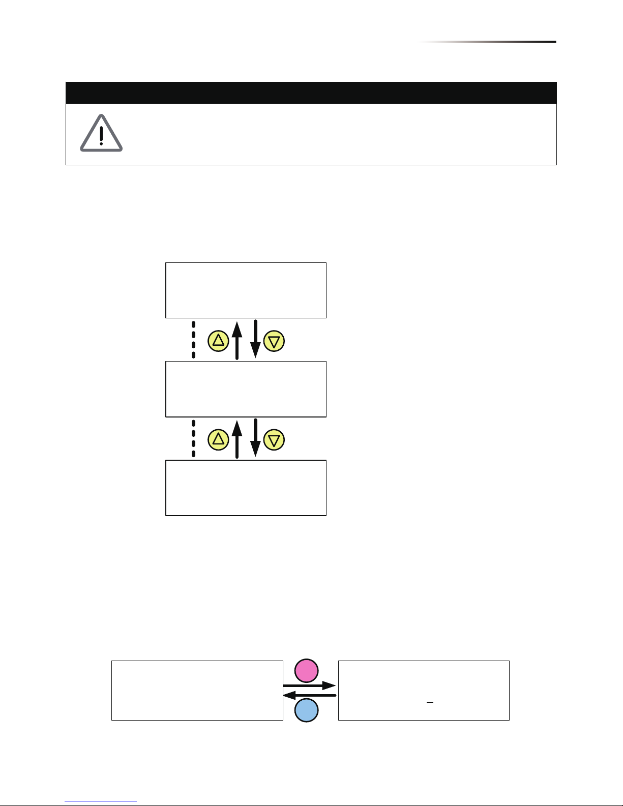
5.2 First startup
At first startup, users have to feed in AC power and switch on the Manual
Switch. Inverter will start up on AC power and LCD display panel will come
live. Please set Language and Country according to your region and make
sure that there is no any error, fault or warning showing on home page.
Now you can feed in DC power and wait for inverter initially self-test about
2 minutes. If there is enough power generated from PV array, inverter will
start to feen in power to grid.
First Startup(M30A/ M50A)
ENT
Are you sure to
set country :
XXX
Yes / ►No
EXIT
ENT
EXIT
Select Country,
AU/NZ
Austria
Belgium
►
Select Language,
English
Deutsch
Français
►
5.2.1. Home Page
When inverter is operating normally, the LCD will display the homepage
as shown in Figure 5-3, user can get the information about output power,
inverter status, E-today, date and time.
Pressing any key in home page can users enter the main menu. Press
ESC at main manu or wait 5 minutes without any operation, the display
will return to homepage.
21. Jun 2013 13:50
Status:
Power:
E-Today:
7935
192
W
kWh
On Grid
Today Energy
Inverter Status
Output Power
Day - Time
41
Turn on PV inverter

5.2.2. Power Meter
This page displays voltage, current and power from both AC and DC side.
5.2.3. Energy Log
User can view the inverter’s life energy and life runtime via Energy Log page.
V 230 230 230
I 11.5 11.5 11.5
P 2645 2645 2645
L1 L2 L3AC
Power:
Frequency:
E-Today:
AC
7935
50.00
24
W
Hz
kWh
ENT
or
V 544 472
I 8.0 8.3
P 4350 3915
DC1 DC2DC
ENT
or
Figure 5-4 Power meter page
Figure 5-5 Energy log Page
Energy Log
Life Energy:
Runtime:
29200
7302
kWh
Hrs
42
Turn on PV inverter

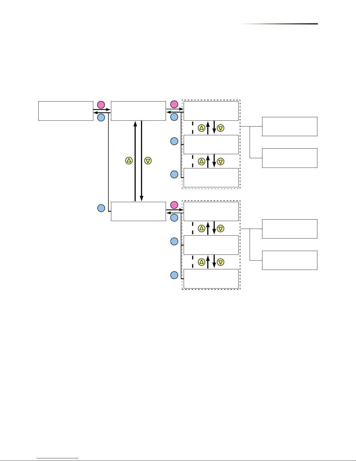
5.2.4. Event Log
Event Log has two subpages: Error Events page and Grid Report page.
Error Events page displays all the events (Error and Fault) and it can show
30 records at a time. Grid Report page only displays the error that occurred
at grid side, and it can show 5 records at a time.
1. 20/02/2013 15:30
AC Freq High
2. 19/02/2013 09:30
AC Volt Low
29. 20/02/2013 15:30
AC Freq High
30. 19/02/2013 09:30
AC Volt Low
ENT
EXIT
ENT
or
ENT
or
EXIT
Error Events
Grid Report
►
Error Events
Grid Report
►
1. 20/02/2013 15:30
No Gird
2. 19/02/2013 09:30
AC Volt Low
5. 20/02/2013 15:30
AC Freq High
ENT
or
ENT
or
ENT
EXIT
EXIT
Figure 5-6 Event log Page
43
Turn on PV inverter

5.2.5. Inverter Information
This page can helps user to recognize the inverter. First section displays
serial number, installation date, ID, and firmware version. Another 3 sections
displays the settings of inverter functions. For more infromation about
these settings, please refer to 5.2.7 Install Settings, 5.2.8 Active/Reactive
power, and 5.2.9 FRT (Fault ride through).
5.2.6. General Settings
Users can set Language, Date and Time, and RS-485 communication
baud rate in this page.
Figure 5-7 Inverter information page
Figure 5-8 General settings page
Language
Date and Time
Baud Rate
►
ENT
or
S/N: RN11179CB0
Install: 30/04/2014
DSP 1.80 Red. 1.65
Comm. 1.65 ID: 002
ENT
or
AC connection:
Max. Power:
Dry Cont:
EPO:
3P4W
52500W
Insulation
Normal Close
Country:
Insulation:
Baud Rate:
Germany MV
1200k
19200bps
ENT
or
►
Grid Settings
Active Pwr Settings
React Pwr Settings
FRT Settings
Link to settings page but read only
44
Turn on PV inverter
5.2.7. Install Settings
To enter Install Settings page, users have to enter correct password.
There are 3 sets of password with different permissions: user level, installer
level, and manufacturer level. The following sub-sections will introduce
the setting items in Install Settings page of user level and installer level.
CAUTION!
The settings in Install Settings page can only be adjusted by qualified
installers or engineers. Changing these settings may result in damage
to the inverter and other equipment.
Inverter ID: 002
Insulation
Country
Grid Settings
►
DC Injection
Dry Contact
RCMU
EPO
►
ON
Normal Close
AC Connection
Anti-islanding
Max Power
Return to Factory
►
3P4W
ON
52500W
User Level:
- Inverter ID
- Insulation
- Country
- Dry Contact
- EPO
- AC Connection
- Max. Power
Manufacturer Level:
- All Settings
Installer Level:
- Inverter ID
- Insulation
- Country
- Grid Settings
- Dry Contact
- EPO
- AC Connection
- Max. Power
Figure 5-9 Install settings page
Figure 5-10 Inverter ID page
5.2.7.1. Inverter ID
Inverter ID is used in RS-485 communication, for PC recognizing the
inverter. If users connect several inverters together via RS-485, each
inverter must have different ID.
ENT
EXIT
Setting ID:
ID = 0
02
Inverter ID: 002
Insulation
Country
Grid Settings
►
45
Turn on PV inverter

Figure 5-11 Insulation page
Figure 5-12 Country page
5.2.7.2. Insulation
Before connecting to grid, inverter will measure the impedance between
the PV array and PE first. M30A & M50A models provide 4 types of
impedance measurement methods (ON, Plus Grounded, Minus Grounded,
and OFF) and 2 impedance limits. Installer must select the appropriate
method based on PV array’s wiring.
5.2.7.3. Country
Each country has its own electricity regulations. Installer must select the
country correctly.
ENT
EXIT
ENT
EXIT
EXIT
Inverter ID: 002
Insulation
Country
Grid Settings
►
Mode: ON
Resistance: 1200kΩ
►
ON
Plus Grounded
Minus Grounded
OFF
►
ENT
EXIT
Mode: ON
Resistance: 1200kΩ
►
1200kΩ
700kΩ
►
ENT
EXIT
Inverter ID: 002
Insulation
Country
Grid Settings
►
AU/NZ
Austria
Belgium
China
►
46
Turn on PV inverter
5.2.7.4. Grid Settings
Grid settings page includes the voltage and frequency protection points.
These protection points are linked to electricity regulations.
If there is no any special requirement, please do not change any grid settings.
Figure 5-13 Grid Settings page
Inverter ID: 002
Insulation
Country
Grid Settings
►
ENT
EXIT
Voltage Protection
Freq. Protection
Reconnect T
P Ramp Up
►
ENT
EXIT
High Off
High On
High Off T
Low Off
►
276.0V
259.0V
0.3s
184.0V
Low On
Low Off T
Hi Off Slow
Hi On Slow
►
219.0V
0.3s
276.0V
259.0V
Hi Off Sl T
Lo Off Slow
Lo On Slow
Lo Off Sl T
►
600.0s
184.0V
219.0V
1.0s
Voltage Protection
Freq. Protection
Reconnect T
P Ramp Up
►
ENT
EXIT
High Off
High On
High Off T
Low Off
►
51.50Hz
50.05Hz
0.1s
47.50Hz
Low On
Low Off T
Hi Off Slow
Hi On Slow
►
47.55Hz
0.1s
65.00Hz
64.95Hz
Hi Off Slow T
Lo Off Slow
Lo On Slow
Lo Off Slow T
►
5.0s
45.00Hz
45.55Hz
5.0s
600s
6000%/m
600s
6000%/m
EXIT
EXIT
EXIT
EXIT
EXIT
If user enters wrong settings
Wrong Settings
If user enters wrong settings
Wrong Settings
Press ▲&▼ 5s
Do you want to set
U to the max range?
Yes / ►No
Do you want to set
F to the max range?
Yes / ►No
Press ▲&▼ 5s
47
Turn on PV inverter

5.2.7.5. Dry Contact
Users can choose the trigger condition of dry contact. There are 8 options
in the setting page: Disable, On Grid, Fan Fail, Insulation, Alarm, Error,
Fault, and Warning. Please refer to Table 5-2 for more details about these
options.
Dry Contact Trigger Timing
No action.
Inverter is connecting to grid.
Fan Fail occurs.
Insulation test fail.
Any error, fault, or warning occurs.
Any Error occurs.
Any Fault occurs.
Setting
Disable
On Grid
Fan Fail
Insulation
Alarm
Error
Fault
Any Warning occurs.Warning
Table 5-2 Dry Contact Trigger Setting
Figure 5-14 Dry Contact page
DC Injection
Dry Contact
RCMU
EPO
►
On Grid
ON
Normal Close
ENT
EXIT
►
Alarm
Error
Fault
Warning
►
Disable
On Grid
Fan Fail
Insulation
EXIT
48
Turn on PV inverter

5.2.7.6. EPO
EPO function has 2 detection methods: Normal Open and Normal Close.
Normal Open means EPO pins are usually open-circuited. When these
two pins are short-circuited, inverter will shut down immediately.
Normal Close is contrary to Normal Open. Please choose an appropriate
detection method according to your needs.
5.2.7.7. AC connection
RPI M30A and M50A models can support 3P3W and 3P4W system.
Please select the correct AC wiring type.
5.2.7.8. Max. Power
Electricity regulation in some area requests that inverter must have power
limit function. In these areas, users can adjust Max. Power to limit the
maximum output power of the inverter.
DC Injection
Dry Contact
RCMU
EPO
►
ON
Normal Close
Figure 5-15 EPO page
Figure 5-16 EPO page
Figure 5-17 Max. Power page
AC Connection
Anti-islanding
Max. Power
Return to Factory
►
3P4W
ON
52500W
AC Connection
Anti-islanding
Max. Power
Return to Factory
►
3P4W
ON
52500W
49
Turn on PV inverter

Figure 5-18 Active/Reactive power page
Figure 5-19 Power Limit page
Figure 5-20 Power vs Frequency page
5.2.8. Active/Reactive power
A password is required to enter Active/Reactive Power page.
This page includes two kinds of function: active power control and reactive
power control. In active power control function, there are 3 control modes:
Power Limit, Power vs. Frequency, and P(V). In reactive power control
function, there are 4 control modes: Constant cosphi, cosphi(P), Constant
Q, and q(V). These modes will be introduced in next section.
5.2.8.1. Power Limit
This control mode can reduce the output power to a percentage of inverter’s
rated power. Users can limit the output power by set the Set Point in Power
Limit page.
5.2.8.2. Power vs. Frequency
Inverter will reduce output power when grid frequency rises up if this mode
enabled. Users can tune the parameters in Power vs. Frequency page
to change the inverter’s behavior.
Power Limit
Power vs. Frequency
P(V)
►
ENT
EXIT
Mode:
Set Point:
►
ON
100%
Power Limit
Power vs. Frequency
P(V)
►
Mode
F start
F recovery
Gradient
►
ENT
EXIT
EXIT
ON
50.20 Hz
50.20 Hz
40%
T recovery
►
300s
ENT
EXIT
Active Power Ctrl
Reactive Power Ctrl
►
Warning:
Adj. would affect
energy production.
Password:
****
50
Turn on PV inverter

P
Pm
f
start =
f
(Hz)
Gradient
P
Pm
f
recovery
f
start
f
(
Hz
)
Gradient
Germany MV & ItalyOthers
f
recoveryfprotection
f
protection
Figure 5-21 Power vs Frequency parameters
Figure 5-22 P(V) page
5.2.8.3. P(V)
When grid voltage rises up to a lock-in voltage(V lock-in) and inverter’s
present output power is greater than lock-in power(P lock-in), inverter
will reduce the output power and keep it at a certain value(P lock-out)
until grid voltage drop back to lock-out voltage(V lock-out) and passing
a certen time(T revcovery).
Power Limit
Power vs. Frequency
P(V)
►
ENT
EXIT
EXIT
Mode
P lock-in
P lock-out
V lock-in
►
OFF
20%
5%
253.0V
V lock-out
T recovery
►
248.4V
300s
51
Turn on PV inverter

5.2.8.4. Constant cosphi
Inverter can feed in a fixed reactive power to grid. Users can set the power
factor(cosphi) in Constant cosphi page.
5.2.8.5. Cosphi (P)
Cosphi (P) is a function that inverter will feed in reactive power when its
output active power reach the setting values. For country Italy MV and
Italy LV, users can set lock-in voltage and lock-out voltage to assign the
operation interval. When grid voltage reach the lock-in voltage(V lock-in),
inverter will enable cosphi (P) function automatically and disabled it when
grid voltage reach lock-out voltage(V lock-out).
►
Constant cosphi
Cosphi (P)
Constant Q
Q(V)
ENT
EXIT
Mode
cosphi
►
OFF
Ind 1.00
Figure 5-23 Constant cosphi page
Figure 5-24 Cosphi (P) page
►
Constant cosphi
Cosphi (P)
Constant Q
Q(V)
ENT
EXIT
EXIT
Mode
Q upper
P lower
Q lower
►
OFF
Ind 1.00
45%
Ind 0.90
P upper
V lock-in
V lock-out
►
90%
241.5V
230.0V
Q upper
Q lower
P/Pn
1
cosφ
P lower P upper
Figure 5-24 Cosphi (P) page
52
Turn on PV inverter

Figure 5-26 Constant Q parameters
Figure 5-27 Q(V) page
5.2.8.6. Constant Q
Like Constant cosphi function, users can assign a percentage of reactive
power in Constant Q page.
5.2.8.7. Q(V)
Q(V) is a control mode that inverter will provide reactive power accroding
to grid voltage. For country Italy MV and Italy LV, users can set lock-in
power and lock-out power to assign Q(V) function operation interval.
►
Constant cosphi
Cosphi (P)
Constant Q
Q(V)
ENT
EXIT
Mode
Fix Q
►
OFF
Ind 90%
►
Constant cosphi
Cosphi (P)
Constant Q
Q(V)
ENT
EXIT
EXIT
EXIT
Mode
V1s
V2s
Qs limit
►
OFF
248.4V
253.0V
Ind 44%
V1i
V2i
Qi limit
T delay
►
211.6V
207.0V
Cap 44%
10.00s
P lock-in
P lock-out
►
20%
5%
53
Turn on PV inverter

V
1s
V
2s
V
1i
V
2i
Q
i limit
Q
s limit
V
Q
V
1s
V
2s
V
1i
V
2i
Q
i limit
Q
s limit
V
Q
Curve A Curve B
Others Italy MV & Italy LV
Figure 5-28 Q(V) parameters
Figure 5-29 FRT page
Figure 5-30 FRT Parameters
5.2.9. FRT (Fault ride through)
Some area requests that inverter should keep connected to grid when
grid voltage drops suddenly in few seconds. In these areas, users can
enable FRT function and adjust the parameters to meet the requirement.
100%
U1
0
t1
Fault occurence
t3
time
U
grid/Unom
Umin
Udrop
Disconnect from grid
Stay connected
►
General Settings
Install Settings
Active/Reactive Pwr
FRT
ENT
EXIT
ENT
EXIT
EXIT
Mode
Dead Band
Vdrop
t1
►
OFF
-10%
0%
0.30s
U1
t3
K factor
►
20%
3.00s
2.0
Warning:
Adj. would affect
energy production.
Password:
****
54
Turn on PV inverter

6.1 Replace Surge Protection Device (SPD)
RPI M50A_120 model have surge protection device (SPD) at both DC and
AC side. Table 6-1 reveals the specifications of SPD.
Please check the unit regularly. If there are any impaired or loose parts, please
contact your solar installer. Ensure that there are no foreign objects in the path
of the heat outlet.
6.Maintenance
WARNING!
Before any maintenance, please switch AC and DC power off to avoid risk
of electronic shock.
SPD(DC) SPD(AC)
Temperature: -400C~850C
Item fail: Green light will turn off
Manufacturers: ShangHai GEHE Lighti
Temperature: -400C~850C
Item fail: Red upright bulb
Manufacturers: ShangHai GEHE Lighti
Table 6-1 SPD Specifications
Part number: GPU1-ZS1000 Y Part number: GPU1-C4/690/1P Y
Work voltage:1000 Vdc
Work voltage: 690 Vac
Work Amp In (8/20): 20kA
Work Amp In (8/20): 15kA
Rate Amp I max(8/20): 40kA
Rate Amp Imax (8/20): 30kA
55
Maintenance

Once the inverter encounters voltage spikes (e.g. struck by lighting),
SPD will protect the inverter and got damaged. If you find a warning message
“SPD Fail” shown on display panel, please follow the steps below to replace
the SPD.
1.Switch AC and DC power off and wait until LCD display turn off.
2.Loosen the 6 screws on the front cover. (Figure 6-1)
3.Recognize which SPD unit was damaged.
For DC SPD, find the one that green light was turned off.
For AC SPD, find the one that red bulb was erected. (Figure 6-2)
4.Pull out the damaged unit and replace a new one. (Figure 6-3)
5.Reassemble the inverter. Please be careful the waterproof tape for ensure
the protection degree.
Figure 6-1 Remove front cover
RPI M50A
56
Maintenance

Figure 6-3 Pull out the SPD unit
Figure 6-2 Recognize the damaged SPD unit
57
Maintenance

6.2 Replace Internal String Fuse
RPI M50A_120, and RPI M50A_122 models have internal string fuse in
each Plus and Minus DC connector. The specifications of these fuses are
revealed as below.
Please check the fuses if the power generation of inverter is abnormal.
1.Switch AC and DC power off and wait until LCD display turn off.
2.Loosen the 6 screws on the front cover. (Figure 6-1)
3.Pull out the fuse holder and check the fuse. (Figure 6-4)
4.Replace the fuse if necessary.
5.Reassemble the inverter. Please be careful the waterproof tape for ensure
the protection degree.
‐ Item: String Fuse (source 1)
‐ Part number: 10GPV15U0
‐ Rate amp: 15 A
‐ Rate voltage: 1000 V
‐ Manufacturers: Hollyland
‐ Item: String Fuse (source 2)
‐ Part number: 0SPF015.T
‐ Rate amp: 15 A
‐ Rate voltage: 1000 V
‐ Manufacturers: Littelfuse
Figure 6-4 Pull out the fuse
58
Maintenance

Figure 6-5 Replace the fuse
Figure 6-6 Diassembling fan panel
6.3 Clean Fan
Loosen the 4 screws shown in Figure 6-1. Once the screws are loose, pulling
the fan bracket out will expose the connectors. Each fan has one wire
connected.
59
Maintenance

Figure 6-7 Removal of a fan
Figure 6-8 Removal of air outlets
6.4 Replace Fans
In the event that a fan needs to be replaced, user should disassemble the
4 pcs screws around the fans and disconnect the connector right behind the
fan bracket. Then replace new fan and reassemble the 4pcs screws.
6.5 Clean Air Inlet
Unscrew the 4 screws of air inlets and clean them regularly.
60
Maintenance

7.Error message and Trouble Shooting
ERROR
Message Possible cause Action
AC Freq
High
(E01)
1.
Actual utility frequency is over
the OFR setting
2. Incorrect country setting
3. Detection circuit malfunction
1. Check the utility frequency on the
inverter terminal
2. Check country setting
3.
Check the detection circuit inside the
inverter
AC Freq
Low
(E02)
1.
Actual utility frequency is under
the UFR setting
2.
Incorrect country or Grid setting
3. Detection circuit malfunction
1. Check the utility frequency on the
inverter terminal
2. Check country & Grid setting
3.
Check the detection circuit inside the
inverter
Grid Quality
(E07)
Non-linear load in Grid and near
to inverter
Grid connection of inverter need to be
far away from non-linear load if necessary
HW Con.
Fail
(E08)
1. Wrong connection in AC plug
2. Detection circuit malfunction
1.
Check the AC connection, must accords
to manual
2.
Check the detection circuit inside the
inverter
No Grid
(E09)
1. AC breaker is OFF
2. Disconnect in AC plug
1. Switch on AC breaker
2.
Check the connection in AC plug and
make sure it connects to inverter
AC Volt
Low
(E10, E15,
E20)
1. Actual utility voltage is under
the UVR setting
2.
Incorrect country or Grid setting
3.
Wrong connections in AC plug
4. Detection circuit malfunction
1. Check the utility voltage connection
to the inverter terminal
2. Check country & Grid setting
3. Check the connection in AC plug
4.
Check the detection circuit inside the
inverter
AC Volt
High
(E11, E13,
E16, E18,
E21, E23)
1.
Actual utility voltage is over the
OVR setting
2.
Utility voltage is over the Slow
OVR setting during operation
3.
Incorrect country or Grid setting
4. Detection circuit malfunction
1.
Check the utility voltage on the inverter
terminal
2.
Check the utility voltage on the inverter
terminal
3. Check country & Grid setting
4. Check the detection circuit inside the
inverter
Solar1
High
(E30)
1. Actual Solar1 voltage is over
1000Vdc
2. Detection circuit malfunction
1. Modify the solar array setting, and
make the Voc less than 1000Vdc
2.
Check the detection circuit inside the
inverter
61
Error message and Trouble Shooting

ERROR
Message Possible cause Action
Solar2
High
(E31)
1. Actual Solar2 voltage is over
1000Vdc
2. Detection circuit malfunction
1. Modify the solar array setting, and
make the Voc less than 1000Vdc
2.
Check the detection circuit inside the
inverter
Insulation
(E34)
1. PV array insulation fault
2. Large PV array capacitance
between Plus to Ground or
Minus to Ground or both.
3. Detection circuit malfunction
1. Check the insulation of Solar inputs
2.
Check the capacitance, dry PV panel
if necessary
3.
Check the detection circuit inside the
inverter
Table 7-1 Error Message
Warning
Message Possible cause Action
Solar1
Low
(W01)
1.
Actual Solar1 voltage is under
the limit
2. Some devices were damaged
inside the inverter if the actual
Solar1 voltage is close to "0"
3. Detection circuit malfunction
1. Check the Solar1 voltage connection
to the inverter terminal
2. Check all switching devices in boost1
3. Check the detection circuit inside the
inverter
Solar2
Low
(W02)
1.
Actual Solar2 voltage is under
the limit
2. Some devices were damaged
inside the inverter if the actual
Solar2 voltage is close to "0"
3. Detection circuit malfunction
1.
Check the Solar2 voltage connection
to the inverter terminal
2.
Check all switching devices in boost2
3.
Check the detection circuit inside the
inverter
HW FAN
(W11)
1. One or more fans are locked
2.
One or more fans are defective
3. One ore more fans are
disconnected
4. Detection circuit malfunction
1. Remove the object that stuck in the
fan(s)
2. Replace the defective fan(s)
3. Check the connections of all fans
4. Check the detection circuit inside the
inverter
SPD Fail
1. Inverter was struck by lighting.
2.
One or more SPD are defective
3. One or more SPD are
disconnected
4. Detection circuit malfunction
1. Check inverter’s status
2. Replace the defective SPD
3. Check the connections of SPDs
4. Check the detection circuit inside the
inverter
Table 7-2 Warning Message
62
Error message and Trouble Shooting

FAULT
Message Possible cause Action
DC
Injection
(F01, F02,
F03)
1. Utility waveform is
abnormal
2. Detection circuit
malfunction
1. Check the utility waveform.
Grid connection of inverter need to be
far away from non-linear load if necessary
2. Check the detection circuit inside the
inverter
Temperature
(F05)
1. The ambient is over 60℃
(The installation is abnormal)
2.
Detection circuit malfunction
1. Check the installation ambient and
environment
2. Check the detection circuit inside the
inverter
Temperature
(F07)
1. Ambient temperature is
<-30 ℃
2. Detection circuit
malfunction
1. Check the installation ambient and
environment
2. Check the detection circuit inside the
inverter
HW NTC1
Fail
(F06)
1. Ambient temperature
>90℃ or <-30℃
2. Detection circuit
malfunction
1. Check the installation ambient and
environment
2. Check the detection circuit inside the
inverter
HW NTC2
Fail
(F08)
1. Ambient temperature
>90℃ or <-30℃
2. Detection circuit
malfunction
1. Check the installation ambient and
environment
2. Check the detection circuit inside the
inverter
HW NTC3
Fail
(F09)
1. Ambient temperature
>90℃ or <-30℃
2. Detection circuit
malfunction
1. Check the installation ambient and
environment
2. Check the detection circuit inside the
inverter
HW NTC4
Fail
(F10)
1. Ambient temperature
>90
℃ or <-30℃
2. Detection circuit
malfunction
1. Check the installation ambient and
environment
2. Check the detection circuit inside the
inverter
DC RLY
Fail
(F13)
1. Driver circuit for relay is
defective
2. Relay(s) is defective
3.
Detection circuit malfunction
(Inverter voltage)
1.
Check the input voltage, must >150Vdc
2. Replace the defective relay
3. Check the detection circuit inside the
inverter
HW DSP
ADC1
(F15)
1. Insufficient input power
2. Auxiliary power circuitry
malfunction
3. Detection circuit
malfunction
1.
Check the input voltage, must >150Vdc
2. Check the auxiliary circuitry inside the
inverter
3. Check the detection circuit inside the
inverter
63
Error message and Trouble Shooting

FAULT
Message Possible cause Action
HW DSP
ADC2
(F16)
1. Insufficient input power
2. Auxiliary power circuitry
malfunction
3. Detection circuit
malfunction
1.
Check the input voltage, must >150Vdc
2. Check the auxiliary circuitry inside the
inverter
3. Check the detection circuit inside the
inverter
HW DSP
ADC3
(F17)
1. Insufficient input power
2. Auxiliary power circuitry
malfunction
3. Detection circuit
malfunction
1.
Check the input voltage, must >150Vdc
2. Check the auxiliary circuitry inside the
inverter
3. Check the detection circuit inside the
inverter
1. Insufficient input power
2. Auxiliary power circuitry
malfunction
3. Detection circuit
malfunction
1.
Check the input voltage, must >150Vdc
2. Check the auxiliary circuitry inside the
inverter
3. Check the detection circuit inside the
inverter
1. Insufficient input power
2. Auxiliary power circuitry
malfunction
3. Detection circuit
malfunction
1.
Check the input voltage, must >150Vdc
2. Check the auxiliary circuitry inside the
inverter
3. Check the detection circuit inside the
inverter
HW Red
ADC1
(F18)
HW Red
ADC2
(F19)
HW Eff.
(F20)
1. The calibration is incorrect
2. Current feedback circuit is
defective
1. Check the accuracy of current and
power
2. Check the current feedback circuit
inside the inverter
HW
COMM1
(F23)
1. DSP is idling
2. The communication
connection is disconnected
3. The communication circuit
malfunction
1. Check reset and crystal in DSP
2. Check the connection between DSP
and COMM
3. Check the communication circuit
HW
COMM2
(F22)
1. Red. CPU is idling
2. The communication
connection is disconnected
1. Check reset and crystal in Red. CPU
2. Check the connection between Red.
CPU and DSP
Ground Cur.
(F24)
1. PV array insulation fault
2.
Large PV array capacitance
between Plus to Ground or
Minus to Ground
3. Either side of boost driver
or boost choke malfunction
4.
Detection circuit malfunction
1. Check the insulation of Solar inputs
2. Check the capacitance (+ <-> GND &
- <-> GND), must < 2.5uF. Install a
external transformer if necessary
3. Check boost driver & boost choke
4. Check the detection circuit inside the
inverter
64
Error message and Trouble Shooting

FAULT
Message Possible cause Action
HW Con. Fail
(F26)
1.
Power line is disconnected
inside the inverter
2. Current feedback circuit is
defective
1.
Check the power lines inside the inverter
2.
Check the current feedback circuit inside
the inverter
RCMU Fail
(F27)
1. RCMU is disconnected
2.
Detection circuit malfunction
1.
Check the RCMU connection inside the
inverter
2. Check the detection circuit inside the
inverter
1. One or more relays are
sticking
2. The driver circuit for the
relay malfunction
1. Replace the defective relay(s)
2.
Check the driver circuit inside the inverter
1. One or more relays are
abnormal
2. The driver circuit for the
relay malfunction
3. The detection accuracy is
not correct for Vgrid and Vout
1. Replace the defective relay(s)
2.
Check the driver circuit inside the inverter
3.
Check the Vgrid and Vout voltage detect
on accuracy
RLY Short
(F28)
RLY Open
(F13, F29)
Bus Unbal.
(F30)
1. Not totally independent or
parallel between inputs
2. PV Array short to Ground
3.
Driver for boost is defective
or disconnected
4.
Detection circuit malfunction
1. Check the inputs connections
2. Check the PV Array insulation
3. Check the driver circuit for boost inside
the inverter
4. Check the detection circuit inside the
inverter
HW Bus OVR
(F31, F33, F35)
1.
Driver for boost is defective
2. Voc of PV array is over
1000Vdc
3. Surge occurs during
operation
4.
Detection circuit malfunction
1. Check the driver circuit for boost inside
the inverter
2.
Modify the solar array setting, and make
the Voc less than 1000Vdc
3. N/A
4. Check the detection circuit inside the
inverter
AC Cur. High
(F36, F37, F38,
F39, F40, F41)
1. Surge occurs during
operation
2. Driver for inverter stage is
defective
3.
Switching device is defective
4.
Detection circuit malfunction
1. N/A
2.
Check the driver circuit in inverter stage
3. Check all switching devices in inverter
stage
4.
Check the detect circuit inside the inverter
HW CT A Fail
(F42)
1.
Test current loop is broken
2. CTP3 is defective
3.
Detection circuit malfunction
1.
Check the connection of CNP4 to CNM4
2. Replay CTP3 with new one
3. Check the detection circuit inside the
inverter
65
Error message and Trouble Shooting

FAULT
Message Possible cause Action
HW CT B Fail
(F43)
1.
Test current loop is broken
2. CTP4 is defective
3.
Detection circuit malfunction
1.
Check the connection of CNP4 to CNM4
2. Replace CTP4 with new one
3. Check the detection circuit inside the
inverter
HW CT C Fail
(F44)
1. Test current loop is broken
2. CTP5 is defective
3.
Detection circuit malfunction
1.
Check the connection of CNP4 to CNM4
2. Replace CTP5 with new one
3. Check the detection circuit inside the
inverter
1. Large Grid harmonics
2.
Switching device is defective
3.
Detection circuit malfunction
1.
Check the utility waveform. Grid connection
of inverter need to be far away from
non-linear load if necessary
2. Check all switching devices in inverter
stage
3. Check the detection circuit inside the
inverter
The detection circuit for
synchronal signal malfunction
Check the detection circuit for synchronal
signal inside the inverter
HW AC OCR
(F45)
HW ZC Fail
(F50)
DC Cur. High
(F60, F61,
F70, F71)
1. Switching device in boost
is defective
2.
Driver for boost is defective
3. Input current detection
circuit malfunction
1. Check all switching device in boost
2.
Check the driver curcuit for boost inside
the inverter
3. Check input current detection circuit
Table 7-3 Fault Message
66
Error message and Trouble Shooting

If it is necessary to put the device out of operation for maintenance and/or storage,
please follow the instructions below.
8.De-Commissioning
WARNING!
To avoid injuries, please follow the procedures:
• Switch off Manual Switch to shut down the inverter.
• Switch off AC circuit breaker to disconnect with electricity grid.
• Switch off the PV array switch to disconnect from the PV array.
• Use proper voltmeter to confirm that the AC and DC power are
disconnected from the unit.
• Remove the AC wiring immediately to completely disconnect from
electricity grid.
• Remove the DC wiring to disconnect from PV Array.
• Remove the communication module RS-485 connection from the
computer connection.
67
De-Commissioning

9.Technical Data
GENERAL
Enclosure
Operating temperature
Operating Altitude
Powder coated aluminum
-25~60℃, full power up to 40℃
(Please refer to figure 9-1 to 9-6.)
2000m
Relative humidity 0 – 100% non condensing.
Environmental category Outdoor, wet locations
Protection degree IP65 (Electronics)
Pollution degree II
Overvoltage category AC output :III, DC Input :II
Maximum backfeed
current to the array
0
Galvanic isolation NO
Safety class Class I metal enclosure with protective earth
Weight 74kg
Dimensions(W*H*D) 612 × 740 × 278mm
48.5kg
612 × 625 × 278mm
Connectors Weather resistant connectors
DC INPUT (Solar side)
Recommended PV power
Maximum input power
Nominal voltage
Operating voltage
Startup voltage
35kW 58kW
≦
38kW
≦
63kW
1000V 1100V*
Rated power
31.5kW 52.5kW
600Vdc
200Vdc – 1000 Vdc
> 250 Vdc
Start up power
40W
MPP tracker
Parallel inputs: 1 MPP tracker
Separate inputs: 2 MPP trackers
Absolute maximum voltage
RPI M30A RPI M50A
* Inverter stop operating when input voltage large than 1000V.
68
Technical Data

MPP range (rated power)
Balanced inputs (50/50)
520-800Vdc 520-800Vdc
700-800Vdc 700-800Vdc
Maximum unbalanced inputs
350-800Vdc
67%
33% 350-800Vdc
RPI M30A RPI M50A
DC INPUT (Solar side)
AC OUTPUT (Grid side)
Number of inputs
Rated current
Maximum short circuit
current per MPPT (Isc)
Nominal power
Maximum power
Voltage
Nominal current
Maximum current
Inrush current
Maximum output fault
current (rms)
Maximum output over
current protection
Frequency
Rated 50/60Hz
(Programmable 45Hz - 65Hz)
Total harmonic distortion < 3 %
Power factor
> 0.99 @ full power
Adjustable: 0.80 leading – 0.80 lagging
Tare loss
DC current injection
Maximum efficiency
EU efficiency
AC connector
<0.5% rated current
3 Ph + N + PE; 3-phase AC plug that meets IP67
and specifications in table 4-2.
6 pairs MC4 10 pairs MC4
30A * 2 50 A * 2
36A
(Each String 12A)
60A
(Each String 12A)
50kW / 50kVA
33kW / 33kVA
(Refer to figure 9-1 to 9-3 )
55kW / 55kVA
(Refer to figure 9-4 to 9-6 )
3Ph, 230/400Vac
43.5(230Vac) / 45.5(220Vac) 73A(230Vac) / 76A(220Vac)
50A 80A
150A/100μs 200A/100μs
88.6A 106.4A
57A 91.2A
< 3W < 2.5W
98.5 % 98.6 %
98.2 % 98.4 %
69
Technical Data
30kW / 30kVA

SYSTEM INFORMATION / COMMUNICATION
User interface
Black-on-white character type LCD display
Real time clock
30 events record
External communication 2 RS-485 connections
REGULATIONS & DIRECTIVES
CE conformity Yes
Grid interface
VDE-AR-N 4105
VDE0126-1-1
NB/T 32004
VDE0126-1-1
VDE-AR-N 4105
BDEW,UK G59/3
UTE C15-712
NB/T 32004
Emission EN 61000-6-3
Harmonics EN 61000-3-12
Variations and flicker EN 61000-3-11
Immunity EN 61000-6-2
Immunity
ESD IEC 61000-4-2
RS IEC 61000-4-3
EFT IEC 61000-4-4
Surge IEC 61000-4-5
CS IEC 61000-4-6
PFMF IEC 61000-4-8
Electrical safety IEC 62109-1/ -2
MISCELLANEOUS
Enclosure
Cooling Fan, 3pcs Fan, 5pcs
Mounting bracket
Aluminum with powder coating
Table 9-1 Specifications for RPI M30A/ M50A
RPI M30A RPI M50A
70
Technical Data

71
0.5
0.55
0.6
0.65
0.7
0.75
0.8
0.85
0.9
0.95
1
1.05
1.1
1.15
25℃30℃35℃40℃45℃50℃55℃60
℃
520V
600V
800V
P/Pn*
Pn*=30kW
Ambient Temperature
Temperature Derating of RPI M30A
cos(Φ)=1.0
Figure 9-1 M30A Thermal Derating Curve (cosφ=1.0)
Technical Data

72
Figure 9-2 M30A Thermal Derating Curve (cosφ=0.95)
0.5
0.55
0.6
0.65
0.7
0.75
0.8
0.85
0.9
0.95
1
1.05
1.1
1.15
25℃ 30℃ 35℃ 40℃ 45℃ 50℃ 55℃ 60℃
S(520V)
S(600V)
S(800V)
P(520V)
P(600V)
P(800V)
P/Pn*
Pn*=30kW
Ambient Temperature
Temperature Derating of RPI M30A
cos(Φ)=0.95
Technical Data

73
0.5
0.55
0.6
0.65
0.7
0.75
0.8
0.85
0.9
0.95
1
1.05
1.1
1.15
25℃30℃35℃40℃45℃50℃55℃60
℃
S(520V)
S(600V)
S(800V)
P(520V)
P(600V)
P(800V)
P/Pn*
Pn*=30kW
Ambient Temperature
Temperature Derating of RPI M30A
cos(Φ)=0.9
Figure 9-3 M30A Thermal Derating Curve (cosφ=0.9)
Technical Data

74
Figure 9-4 M50A Thermal Derating Curve (cosφ=1.0)
Ambient Temperature
50%
55%
60%
65%
70%
75%
80%
85%
90%
95%
100%
105%
110%
115%
25 30 35 40 45 50 55 60
℃
Temperature Derating of RPI M50A
520Vdc
600Vdc
800Vdc
P/Pn*
Cos(Ф) =1.0
*Pn=50kW
Ambient Temperature
Technical Data

75
Figure 9-5 M50A Thermal Derating Curve (cosφ=0.95)
50%
55%
60%
65%
70%
75%
80%
85%
90%
95%
100%
105%
110%
115%
25 30 35 40 45 50 55 60
℃
Temperature Derating of RPI M50A
P(520Vdc) S(520Vdc)
P(600Vdc) S(600Vdc)
P(800Vdc) S(800Vdc)
P/Pn*
*Pn=50kW
Cos(Ф) =0.95
Ambient Temperature
Technical Data

76
Figure 9-6 M50A Thermal Derating Curve (cosφ=0.9)
50%
55%
60%
65%
70%
75%
80%
85%
90%
95%
100%
105%
110%
115%
25 30 35 40 45 50 55 60
℃
Temperature Derating of RPI M50A
P(520Vdc) S(520Vdc)
P(600Vdc) S(600Vdc)
P(800Vdc) S(800Vdc)
P/Pn*
99%
*Pn=50kW
Cos(Ф) =0.9
Ambien Temperature
Technical Data

RPI M30A/M50A
操作手冊
三相并网型逆变器
The power behind competitiveness
www.deltaww.com
English 1
77
153
简体中文
繁體中文

1. 信 息
1.1. 关于此手册
1.2. 产品说明
1.3. 其他信息
2. 产品概观
2.1. 逆变器开箱
2.2. 检查内容物
2.3. 产品卷标
2.4. 外观介绍
3. 安装
4. 配线
4.1 配线前准备事项 (有DC保险丝之机种)
4.2. 配线前准备事项 (无DC保险丝之机种)
4.3. AC(市电端)之连接: 三相三线(3P+PE)或三相四线(3P+N+PE)
4.3.1. 保护装置与AC配线图
4.4. 直流输入端(太阳能板电源端) 之连接
4.5. 通讯接口之连接
4.5.1. RS-485之连接
4.5.2. 紧急关机装置与数字输入之连接
4.5.3. 干接点之连接
5. 逆变器开机
5.1. LCD 操作流程
5.2. 首次开机
5.2.1. 主画面
5.2.2. Power Meter
5.2.3. Energy Log
5.2.4. Event Log
5.2.5. Inverter Information
5.2.6. General Settings
5.2.7. Install Settings
5.2.7.1. Inverter ID
5.2.7.2. Insulation
5.2.7.3. Country
5.2.7.4. Grid Settings
5.2.7.5. Dry Contact
5.2.7.6. EPO
5.2.7.7. AC connection
5.2.7.8. Max. Power
5.2.8. Active/Reactive power
5.2.8.1. Power Limit
5.2.8.2. Power vs. Frequency
5.2.8.3. P(V)
5.2.8.4. Constant cosphi
5.2.8.5. Cosphi (P)
5.2.8.6. Constant Q
5.2.8.7. Q(V)
5.2.9. FRT (Fault ride through)
6.设备维护
6.1. 更换突波保护器 (SPD)
6.2. 更换DC保险丝
6.3. 清理风扇
6.4. 更换风扇
6.5. 清理进风口滤网
7.错误讯息与简易故障排除
8.卸除
9.技术数据
80
80
80
80
81
81
81
84
85
87
91
91
96
106
106
110
111
112
113
114
115
115
116
116
117
117
118
119
119
120
120
121
121
122
123
124
124
124
125
125
125
126
127
127
128
128
129
130
130
133
134
135
135
136
142
143
Contents
78

安全规范
本手册提供使用者以下几种常见安全规范:
注 意!
如若不遵守此规范则可能导致机器设备的损毁
警 告!
如若不遵守此规范则可能会导致人员的伤亡
本机任何维修动作只能由制造商进行
危 险!
如若不遵守此规范则将会导致人员的伤亡,
为了避免触电, 请勿私自打开本逆变器外壳
高温危险!
机器正常操作时表面温度可能会有烫伤的危险请勿碰触
79

1. 信 息
1.1 关于此手册
本手册将提供产品之电器规格、安装步骤以及相关设定等信息,本手册适用机
型为RPI M30A/ RPI M50A
1.2 产品说明
本产品为三相非隔离、市电并联型之太阳能逆变器(solar inverter)。
太阳光能量经由太阳能板(PV array)转换成可运用之直流电后,再由逆变器转
换成三相电流输出与市电并联,不支持独立运转(stand alone)
太阳能逆变器工作方式如图1-1, 将太阳能板的直流电源转换成三相交流电源
输出至市电, 达到节能省电的目的。
图 1-1 太阳能逆变器使用说明
1.3 其他信息
如果想获得RPI M30A/ RPI M50A更详细之信息或其它相关产品信息,
可链接至以下网站:http://www.deltaww.com
PV Array Electrical GridSolar Inverter
3PH
AC Distribution
box
Surge arrestor
AC breaker
3 phase, N, PE
80
信 息
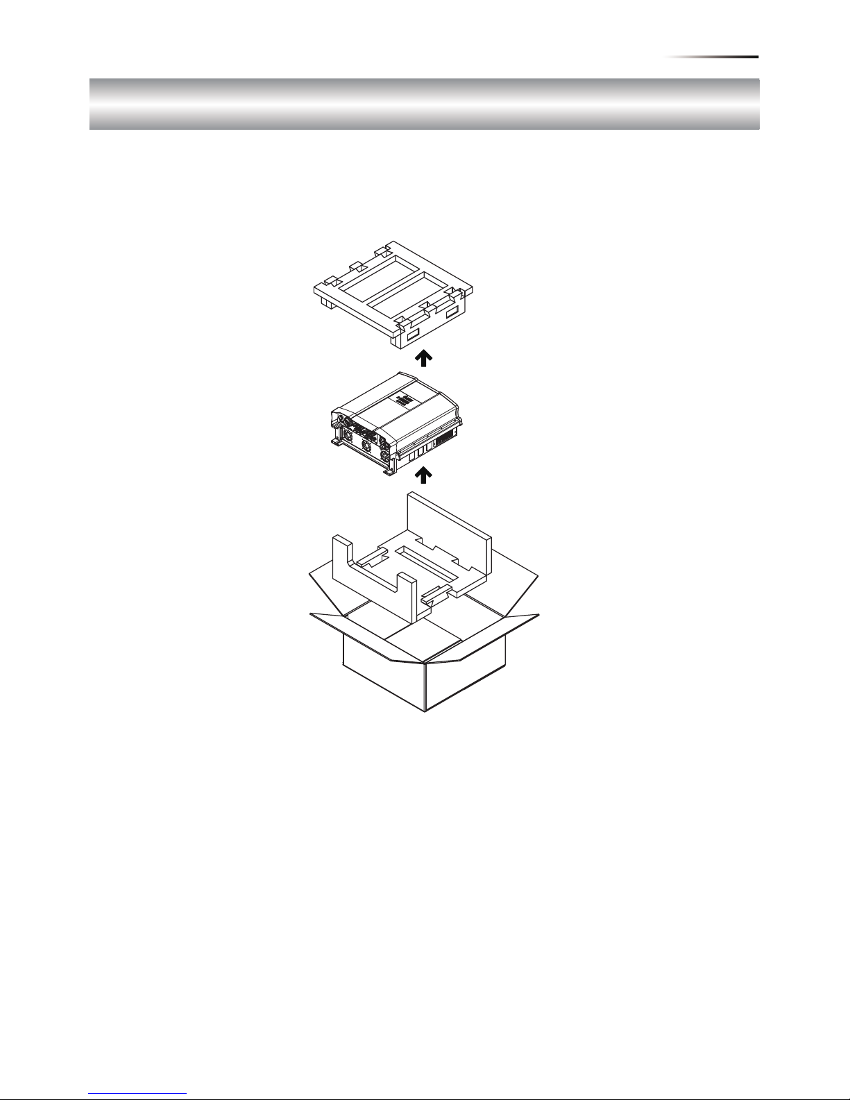
图2-1开箱
RPI M30A/M50A之开箱步骤请参考图2-1。
2. 产品概观
2.1 逆变器开箱
2.2 检查内容物
由于逆变器于运送过程中, 有可能遭遇任何无法预估的状况, 因此建议您按照
以下项目逐项检查:
• 检查外包装箱是否有损坏或破损的现象。
• 检查各项配件是否齐全。详细的配件信息请参考以下的表与图:
RPI M30A机种请参考图2-2与表2-1。
RPI M50A机种请参考图2-3与表2-2。
• 检查外箱之机子型号、序号与包装内机子之型号、序号是否相符。
当您发现包装内、外部有任何损毁的情况或是附件有短缺、损毁,请立即联
系您的逆变器供货商。
81
产品概观

图2-2 M30A内容物清单
RPI M30A
物品 数量 说明
1 太阳能逆变器 1 pcs
1 pcs
1 pcs
1 pcs
RPI系列太阳能逆变器
2 使用说明书
安全规范、安装步骤、产品规格…等
3 AC 接头
壁挂板
AC 连接接头
将太阳能逆变器挂于墙上之壁挂板
4
5
DC 接头 6组 DC 连接接头
表2-1 M30A内容物清单
※本产品不提供接地保险丝,如有需求请自行选用1000V/1A之Midget型保险丝。
①
②
⑤
④
③
82
产品概观

图2-3 M50A内容物清单
※本产品不提供接地保险丝,如有需求请自行选用1000V/1A之Midget型保险丝。
①
②
⑤ ⑥
⑦
④③
RPI M50A
物品 数量 说明
1 太阳能逆变器 1 pcs
1 pcs
1 pcs
1 pcs
RPI系列太阳能逆变器
6 保险丝座 1 pcs 接地保险丝座
7 导电片 2 pcs 将DC+端或DC-端并联之导电片
2 使用说明书
安全规范、安装步骤、产品规格…等
3 AC 接头
壁挂板
AC 连接接头
将太阳能逆变器挂于墙上之壁挂板
4
5
DC 接头 10组 DC 连接接头
表2-2 M50A内容物清单
83
产品概观

2.3 产品卷标
用户可透过产品卷标上的信息得知逆变器之型号,逆变器之型号、规格及序
号皆标示于产品卷标上,关于卷标的位置请参考图 2-4。
RPI M30A/ M50A系列依照DC保险丝与突波保护器的有无可分为三种类型,
请参考表2-3。
型号名称 产品型号
RPI303FA0E1100
RPI503FA0E0000
RPI503FA0E0200
突波保护器
X
V
X
DC保险丝
X
V
V
RPI M30A_121
RPI M50A_120
RPI M50A_122
表 2-3 产品型号
图 2-4 产品卷标
RPI M50A RPI M30A
84
产品概观

2.4 外观介绍
逆变器外部组件如图2-5所示。详细的输出与输入接口请参考图 2-6。
DC输入组数会因机种不同而有所差异。
图 2-5 外观介绍
Display
Air inlet
Label
RPI M50A
Display
Air inlet
Label
RPI M30A
Input / Output
Interfaces
Input / Output
Interfaces
85
产品概观

图 2-6 输出入接口介绍
AC Connector
380/400Vac, 3Ph
Fan *5Manual
Switch
String1
String2
String3
Communication
-RS-485 *2
-EPO *1
-Dry Contact *2
-Digital Input*6
DC1 DC2
String8
String9
String10
-String4
String5
-String6
String7
RPI M50A
DC1 DC2
String1
String2
String3 String4
String5
String6
AC Connector
380/400Vac, 3Ph
Fan *3
Manual
Switch
Communication
-RS-485 *2
-EPO *1
-Dry Contact *2
-Digital Input*6
RPI M30A
86
产品概观

注 意 !
逆变器不可安装在阳光可直射的地方。
警 告!
• 请勿将逆变器安装于易燃性物质附近。
• 请将逆变器安装于稳固之墙上。
3. 安装
本逆变器属于壁挂式机种,安装时请以机身垂直地面,AC/DC接头位于机子
正下方之方式壁挂于墙上。勿将机子安装于倾斜之处。
请依照以下步骤将逆变器安装于墙上:
1.使用12颗M6螺丝将壁挂板锁附于墙上。请参考图3-3。
2.将逆变器附挂于壁挂板上。
3.使用2颗M6螺丝将逆变器固定于墙上。请参考图3-4.
87
安 装

图 3-1壁挂板尺寸
图 3-2 建议和不建议的安装方式
90
Not
Recommended
Not
Recommended
Keep >30 cm from floor and
water if installed this way
88
安 装

M6 Screw *6
Wall
M6 Screw *6
图 3-3 以螺丝固定壁挂板
图 3-4 附挂和固定逆变器
89
安 装

注 意!
• 壁挂板是专为逆变器设计, 而且是逆变器唯一的安装方式。
•
请安装于安全且空旷之场所,方便保养与检修。
• 此产品运转时其周围需有适当空间,如图3-5所示。
• 请安装于视线可及之高度, 以便观察其运转状态与参数设定。
• 请安装于温度介于-25℃~ 60℃的场所。
> 30 cm
> 20 cm
> 50 cm
> 30 cm
> 30 cm
图 3-5 适当安装间距
90
安 装

4.1 配线前准备事项 (有DC保险丝之机种)
4. 配线
警告!电击危险
太阳能板曝晒于阳光下即会产生电力,为避免触电危险,配线前请使用
不透明材料覆盖于太阳能板上,并将太阳能板之电源供应开关转至 OFF。
• M50A机种于DC输入端皆有配接15A的DC保险丝。每个输入串之最大输
入电流不可超过10A。
• 太阳能板可以直接与各个DC输入端独立连接。但并不建议用户使用配电箱
将太阳能板并联后再分接入机子,此接线方式若阻抗不均容易造成电流超
出保险丝负荷。接线方式请参考图 4-1。
• 若您想强制逆变器操作于并联输入模式(仅启动一组MPPT),请于逆变器内
加装2组短路导电片,如图4-2。外部DC端则维持如图4-1之接线方式。
• RPI系列机种内部并未附带隔离变压器。若太阳能板为正端接地或负端接地
时,使用者须于AC 端加装外部隔离变压器,并于逆变器内安装1000V/1A
之midget型接地保险丝与短路导电片。详细的接线方式请参考图 4-3、
图 4-4。
• 当太阳能正端或负端接地时,不可以启动PID功能,同时对地阻抗须设定为
“Plus Grounded”或是“Minus Grounded”。
• 断开直流输入端子前必须先关闭DC与AC电压。
• 不同的DC配线方式需于逆变器控制面板上设定不同的对地阻抗(insulation)
侦测方式,请参考5.2.7 Install Settings。
91
配 线

图 4-1 DC端不接地配线图
1
2
3
4
L1
L2
L3
N
PE
Communication
Wiring
1
2
3
AC Wiring
DC Wiring
Must be Separate
PV strings
*
* RPI M30A can support 3P3W system.
+-+
-
+
-
1
2
3
4
L1
L2
L3
N
PE
Communication
Wiring
1 2
3
AC Wiring DC Wiring
Must be Separate
PV strings
*
* RPI M50A can support 3P3W system.
++++
- -- -
RPI M50A
RPI M30A
92
配 线

bus bar kit *2
DC1+
DC2+
DC1-
DC2-
String 1~5 +
String 6~10 +
String 1~5 -
String 6~10 -
RPI M50A
图 4-2 强制逆变器操作于并联模式
93
配 线

Communication
Wiring
1 2
3
AC Wiring DC Wiring
Separated
connection only
- -- -
Isolated
transformer
Utility
To
Inverter
3Ph,
400Vac
3Ph,
400Vac
++++
DC1+
DC2+
DC1-
DC2-
String 1~5 +
String 6~10 +
String 1~5 -
String 6~10 -
1A
Grounding fuse
bus bar kit
图4-3 M50A DC端负接地配线图
94
配 线

Communication
Wiring
1 2
3
AC Wiring DC Wiring
Separated
connection only
- -- -
Isolated
transformer
Utility
To
Inverter
3Ph,
400Vac
3Ph,
400Vac
++++
1A
Grounding fuse
bus bar kit *2
DC1+
DC2+
DC1-
DC2-
String 1~5 +
String 6~10 +
String 1~5 -
String 6~10 -
图4-4 M50A DC端正接地配线图
95
配 线

4.2 配线前准备事项 (无DC保险丝之机种)
• RPI M30A_121内部并未配备DC保险丝,每组DC输入皆可承受最大30A之
输入电流。每组输入端可以只使用一对DC端子。
• 当太阳能板不接地时,机子DC端可接受并联 或是独立连接。
• RPI系列机种内部并未附带隔离变压器,若太阳能板为正端接地或负端接地
时,DC端仅允许并联配线并需于AC 端加装外部隔离变压器。
• 当太阳能正端或负端接地时,不可以启动PID功能,同时对地阻抗须设定为
“Plus Grounded”或是“Minus Grounded”。
• 不同的DC配线方式需于逆变器控制面板上设定不同的Insulation侦测方式,
请参考5.2.7 Install Settings。
图4-5 M30A_121系统配线图(DC端不接地)
1
2
3
4
L1
L2
L3
N
PE
Communication
Wiring
1
2
3
PV Array
AC Wiring
DC Wiring
Parallel or
Separate
*
* RPI M30A can support 3P3W system.
DC Distribution box
DC1 DC2
96
配 线

图4-6 M30A_121系统配线图(DC正接地或负接地)
Communication
Wiring
1
3
PV Array
AC Wiring
Must be Parallel
Connection
DC Distribution box
(Plus-GND or Minus-GND)
Z
Z
or
Isolated
transformer
Utility
To
Inverter
3Ph,
400Vac
3Ph,
400Vac
Must install a
transformer
2
DC Wiring
当太阳能模组配置选定“Plus Grounded”或是
“Minus Grounded”时,请关闭PID功能。
97
配 线

光伏汇流箱的使用
M50A:
Note for Field Wiring
由于逆变器内部接线与直流配接端子的耐流限制,使用逆变器时,需能确保
每一直流端子的电流不会超出下表限制值,以避免火灾等情事。
下表的电流限制值仅供做为案场配接时的参考依据,不表示逆变器的额定应用值。
-主要是因为光伏汇流箱的输出电流大于M50A上的每一直流端子的
最大电流限制值,16A。所以如下图的应用是不恰当的。 (图4-7)
M50A并不适合与光伏汇流箱串连使用。
RPI M30A_121 32A
RPI M50A_120 16A
RPI M50A_122 16A
表4-1 每一直流端子的最大电流耐受值
图 4-7
>16A >16A
>16A
>16A
98
配 线
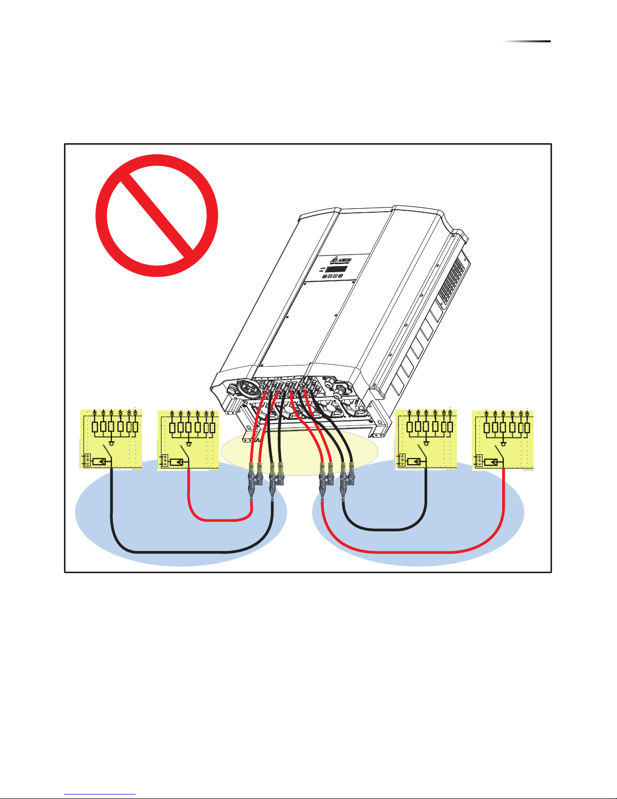
-不建议一个或多个分流接头的使用。(图4-8)
因分流端子后的电流不能保证是平均分配的。
不平衡分流下,局部的直流输入端子仍有可能会超出16A。
图4-8
>16A
>16A
>16A
>16A
Strictly forbiden
Risk of fire on internal
entrance cabling
M50A:
99
配 线

禁止将直流输入端子当做分流接头使用。(图4-10)
因由光伏汇流箱流进逆变器的第一组直流端子电流将远高于限制值32A。
图4-10
M30A:
>32A
>32A
100
配 线
 Loading...