

The power behind competitiveness
Delta PPM N1U_SB1
PPM N1U_SB1
Operation and Installation Manual
www.deltaww.com
㻡㻜㻝㻟㻞㻢㻢㻥㻜㻜
Sub-1G module
PPM N1U_SB1
Essential Points for Safety
・ Request a specialist to dispose of the product.
・ Take care to ensure no water or other liquid gets on the SUB_1G.
・ The product may malfunction or may be damaged by static electricity. Be sure to remove any static electricity on the body, through such means
as touching a metal object nearby, prior to coming into contact with the product.
・ Store the product in a location with the temperature ranging between -30 and +70°C, with the humidity ranging from 30 to 85% RH.
Do not install the product in the following places:
・ Do not expose to extreme fluctuation temperature.
・ Do not expose to salt air.
・ Do not expose to corrosive substances, explosive / flammable GAS, chemicals.
・ Do not install in direct sunlight.
・ Do not install in a place exceeding the operating temperature range (-25 to +55°C).
・ Do not install above 3000m MSL or higher.
・ Do not expose to water vapor, oil vapor, smoke, cotton dust, metal powder, sawdust.
※If installed outdoor, please put it in box which is suitable for outdoor use.
Quick Installation Guide
Warning
Do not allow any fire producing objects to be near the product, or apply any spray, including combustible gases, to the product.
The product may ignite or explode in the unlikely event such an occurrence takes place.
Do not touch the product with wet hands. The product may cause injury due to electric shock or equipment malfunction may occur in
the unlikely event such an occurrence takes place.
Do not disassemble or modify the product. The product may cause injury or fire due to electric shock in the unlikely event such an
occurrence takes place.
When installing the SUB_1G on a wall made of materials that are not wood, be sure to acquire plastic anchors available on the
market to secure SUB_1G on the wall surface. There is danger of injury from the product falling in some rare cases.
Do not install the product in the following types of locations:
There is danger of burnout in some rare cases.
・Locations that are exposed to rain water, such as outdoors or under eaves and the like.
・Locations that are exposed to steam or where the moisture level is 30 to 85% RH, such as lavatories, changing rooms, work sites,
kitchens and the like.
Do not use organic solvents (paint thinners, benzene and the like), strong alkaline substances or strong acidic substances to clean the
case of the product. There is danger of discoloring the case or the equipment malfunctioning in some rare cases.
Do not install the product in a place that is subject to significant effects of vibration and impact.
There is danger of injury from the product falling in some rare cases.
Scope of Delivery
NO.
Product
name
Caution
Qty Remarks Shape
SUB_1G Module
Ŷ SUB_1G Module
1
2
Quick Installation
3
4
SUB_1G
Antenna
Guide
Screw SUB_1G screws
1 unit Main u ni t
1 piece
1 copy
2 pieces
Install antenna to enhance
Wireless Signals.
Installation guide
Name
Network standard support
Data rates
Modulation techniques
Bandwidth
Explanation
FCC/CE/TELEC/NCC
5860bps (BW: 500kHz)
2930bps (BW: 250kHz)
FSK/OOK
FCC: 500kHz
CE: 250kHz
TELEC: 500kHz
NCC: 500kHz
1
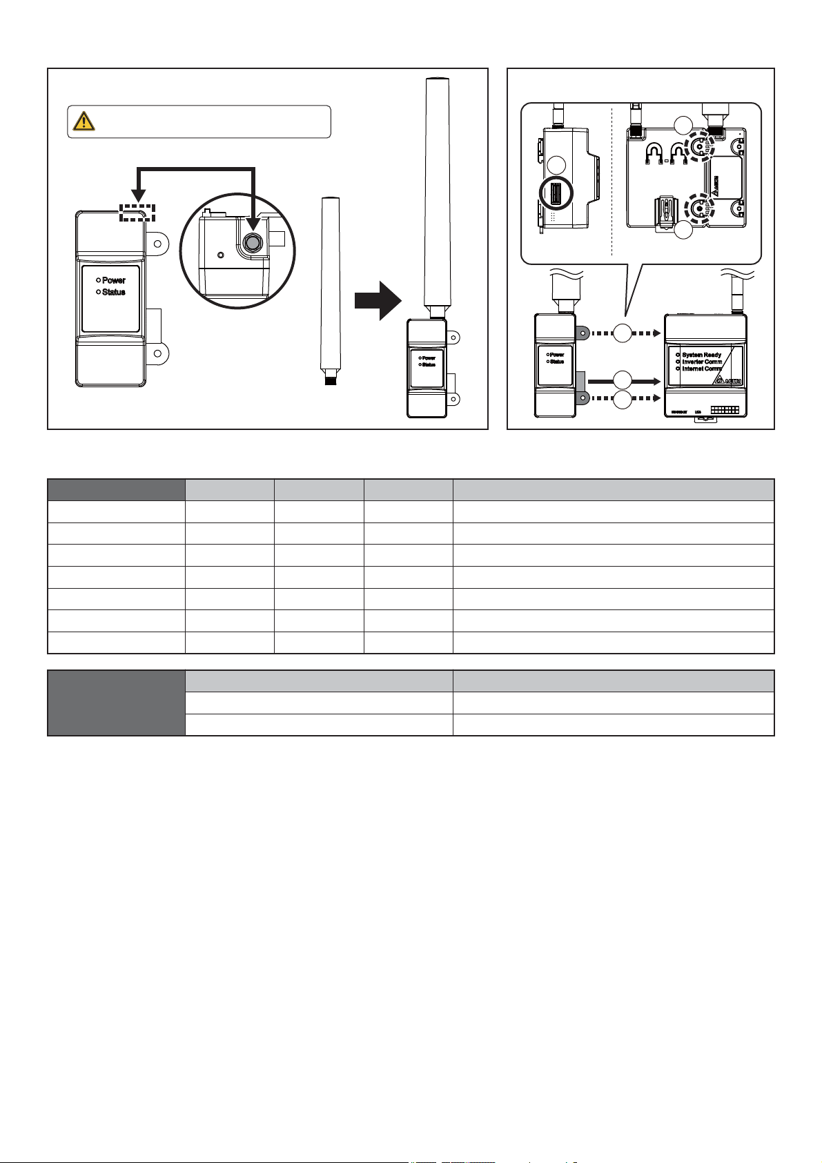
SUB_1G Antenna
Installation Diagram
Ŷ Install antenna to enhance Wireless Signals.
The top of the antenna must face up toward the sky.
SUB_1G Antenna
LED Description
Ŷ Install SUB_1G to Data collector.
2
1
2
* Screw torque required for
assembling: 0.6 N.m
2
1
2
Status
Upgrade N1
Upgrade Module
No Host
Module Not Ready
Ext. Idle
Int. Idle
Normal
Power ON
Red LED
Slow Flash
Slow Flash
OFF
Slow Flash
OFF
OFF
OFF
Yellow LED
OFF
Slow Flash
Slow Flash
OFF
ON
Slow Flash
OFF
Light Green LED
OFF
Green LED
Slow Flash
OFF
Slow Flash
OFF
OFF
OFF
ON
Description
Update N1 card.
Update RF module.
No back-end devices are connected.
Waiting for module initialization.
No Ext. data transmission for more than 300 seconds.
No Int. data transmission for more than 600 seconds.
Connecting.
Description
When the device is receiving power.
Powered off.
2
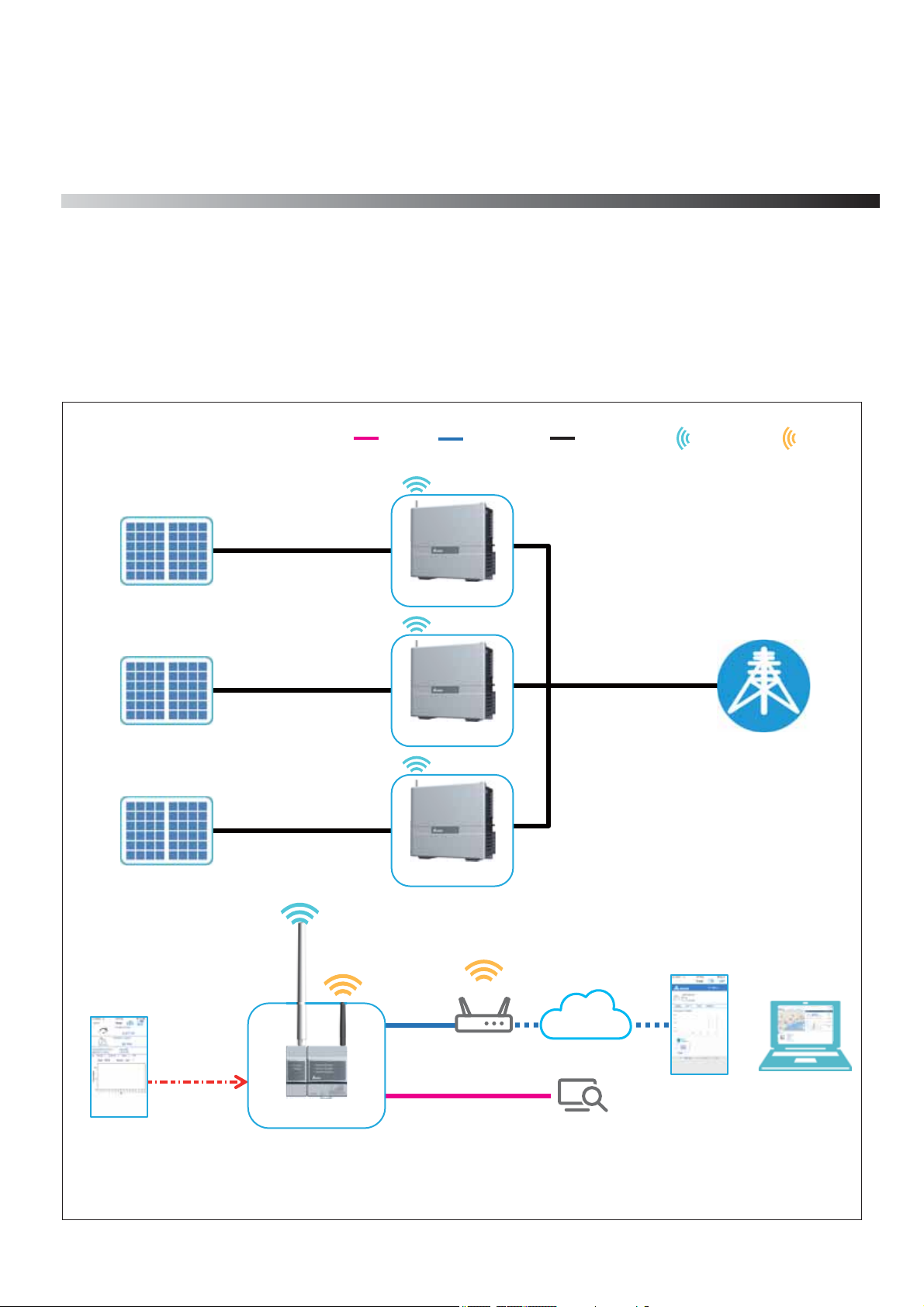
.System Architecture
1
1.1. N1U Application
The WI-FI Inverter is set by operating the DC1 with N1U through the APP. Upload power generation data to Cloud Server for
monitoring.
Note, DC1 data collector is designed for monitoring PV inverter and conducting partial / zero export
application to ensure solar power won't feed back into the grid. With its wired and wireless
communication interface, DC1 can be connected to either MyDeltaSolar or 3rd party cloud
service to realize remote management and optimize the efficiency of the PV system.
PV panel
PV panel
PV panel
LAN Power line
Ethernet
Inverter
Inverter
Inverter
SUB_1G Wi-Fi
Grid
MyDeltaSolar
(APP)
P2P
connection
N1 + DC1
Cloud
MyDeltaSolar
(Cloud)
3rd Party
Monitoring Platform
3
Web browser
(Cloud)
.Commissioning
2
2.1.First startup
To use Delta cloud service, user will have to register Data Collector to colud, please refer following procdeure.
MyDeltaSolar
1. This APP should collocate with Delta Inverter.
2. If inverter is not connected to cloud, you still can monitor inverter operation by APP.
Where can search for MyDeltaSolar APP?
- QR Code: Please scan the QR code to MyDeltaSolar cloud.
- IOS system: Please search “MyDeltaSolar” in App store.
- Android system: Please search “MyDeltaSolar” in Google Play.
QR Code IOS
ŚƩps://itunes.apple.com/ng/app/myd
e lt as olar/ id12716 09228?m t=8
ATTENTION
- Please check the smart phone is connected to the Internet and the communication is good.
ŚƩps://play.google .com/store/apps/de
ta ils ?id=c om. mydeltasola r_1_0 _0.ap p
&hl=zh-TW
Android
4

[ ]
1
After opening the MyDeltaSolar APP, please click [Create account] to apply for
an account. (Suggestion)
If you do not apply for an account, please click the icon on the top right
to access the APP through the P2P connection.
[ ]
2
After checking the box,
click the [OK] button.
[ ]
3
Please fill-in basic information when register an account.
Delta has the option of providing cloud services, allowing users to have
multiple locations anytime, anywhere.
The monitoring and management of the case, all the information will be
collected and stored in the cloud reliably.
Further analysis of the anomaly and automatic notification to the user for
repair as soon as possible and replacement to avoid causing greater
power loss, if not used, will be necessary stored in the local site device
APP is designed to connect and monitor different target devices, if there is
a Data Collector on the plant, you can directly connect to the Data Collector.
Monitor and display multiple Inverters through it
5

[ ]
4
Please go to the Wi-Fi settings page and connect your mobile device to Data
Collector.
[ ]
5
SSID will be “DELTA-
serial number”.
(The serial number information is indicated
on the rating label of the machine)
The password is "DELTASOL"
Authorized representative
Delta Electronics (Netherlands)B.V.
Zandsteen 15, 2132 MZ Hoofddrop
The Netherlands
FCC ID: 2ARTO-PPM-DC1-100
FCC Caution:
This device complies with Part 15 of the FCC Rules.
Operation is subject to the following two conditions:
(1)This device may not cause harmful interference, and
(2)this device must accept any interference received,
including interference that may cause undesired
operation.
MADE IN CHINA
[ ]
6
Product Name: Data Collector
Model: PPM DC1_100
DC Input: 12V /24V
Power Consumption: 5W
Power Micro USB Input: 5V
S/N:
;;;;;;;;;;;;;
CCAM19LP0050T5
After connecting to the Data Collector, please go back to the APP for connection.
Please select your connection mode. [RS-485/ Wi-Fi/ RetroFit] (Please refer to
Chapter 5 for more detailed setting process of each mode)
[RS-485] [Wi-Fi] [RetroFit]
6

1
2 3
[ ]
1. Please click [SEARCH] to detect inverter
2. Please check your inverter serial number (the serial number information is
marked on the rating label of the machine)
3. Set the inverter ID
4.
setting, depending on how many inverter connect to Data collector)
5.
to proceed to the next step.
(Take Wi-Fi connection as example.)
7
After confirming, please click the [SET] button. (please wait 2 to 10 minutes for
Wi-Fi communication will be disconnected from your Data Collector account
at this time.
Please go back to the Wi-Fi settings page and reconnect to the Data Collector.
When the message [Connected Successfully] appears, click the [NEXT] button
4
[ ]
8
Please select proper country code for data collector to set inverter.
5
7

GMT+8
[ ]
9
Please confirm cloud register information and select correct time zone of your
region. (Cloud service will display the information base on country and time zone,
such as weather, map indicate…etc)
[ ]
10
Can change the Wi-Fi password for the Data collector, user can choose “Same
as cloud” or “Change to other”, it is recommended to use the same password
as login cloud to avoid confusion and forget.
8

[ ]
11
Click “Scan” to search Wi-Fi signal which have internet ability and type in the
password. ( DC1 also can connect to cloud by Ethernet, please refer chater 6.6
Network)
Click “Connect” to set Data collector connect to cloud.
[ ]
12
After cloud register success, APP will lead to cloud main page.
9

.Commissioning
2
2.2.
User will have to click ‘Connection’ to set N1U, please refer following procdeure.
Connect to PPM N1U
[ ]
1
After connecting the DC1 on the MyDeltaSolar APP, please click [menu] to
expand the Navagation menu.
If you do not connect to DC1, please refer chapter 2-1. First startup
to access the APP through the P2P connection.
Go to Connection
1
2
[ ]
1. Please checking Sub-1G.
2. Fill in password is ‘1234’, click `[LOGIN] button.
FCC
3
3. Please click the [SCAN] button.
After click the [SCAN] button, start to ‘Scaning Quality’.
4. After scanning band, please choose one frequency.
5. Please click the [SET DATA COLLECTOR COMMUNICATION BAND] button.
6. When the message [Set Successfully] appears, click the [OK] button to proceed to the next step.
FCC
Scaning Quality
2
FCC
4
5
FCC
6
10

FCC
Search Inverters
[ ]
3
1. Please click [SEARCH INVERTER] to proceed to search inverter.
2. After scanning inverter, please choose inverter.
3. When check the inverter box, click [START SUB-1G HANDSHAKING] button.
Start setting inverter ID.
FCC
FCC
FCC
1
2
3
FCC
FCC
FCC
4
5
FCC
FCC
6 7
4. When the message [Set ID complete] appears, click the [OK] button to proceed to set inverter ID.
5. When the message [Get Inverter info success] appears, click the [OK] button to collect inverter info.
6. When the message [Sync time success] appears, click the [OK] button to proceed to Sync time with inverter.
7. When the message [Set monitor on success] appears, click the [OK] button to proceed to set inverter monitor on.
*
Finally, user can monitor inverter or add inverter.
11

Add Inverters
[ ]
4
1. Please click Add inverter.
2. User click [SEARCH INVERTER] button to search inverter.
3. When the message [Search complete] appears, click the [OK] button to
find inverter.
1
3
2
4
7 8 9
5
6
4. After scanning inverter, please choose inverter.
5. When check the inverter box, click [START SUB-1G HANDSHAKING] button.
Start setting inverter ID.
6. When the message [Set ID complete] appears, click the [OK] button to proceed to set inverter ID.
7. When the message [Get Inverter info success] appears, click the [OK] button to collect inverter info.
8. When the message [Sync time success] appears, click the [OK] button to proceed to Sync time with inverter.
9. When the message [Add Inverter success] appears, click the [OK] button to proceed to add inverter.
12

Information
[ ]
5
1. After connecting the DC1 on the MyDeltaSolar APP, please click [menu] to expand the Navagation menu.
2. After click [INFO] on Navigation menu, see gerneal info, total energy, inverter info, input, output, operation data,
string current, de-rating log, fw version.
1
2
13

Warning
FCC Part 15.19
This device complies with Part 15 of the FCC Rules. Operation is subject to the following two conditions:
(1) this device may not cause harmful interference and
(2) this device must accept any interference received, including interference that may cause undesired operation.
FCC Part 15.21 information for user
You are cautioned that changes or modifications not expressly approved by the party responsible for compliance
could void your authority to operate the equipment.
FCC Section 15.105 Information to the user.
NOTE:
This equipment has been tested and found to comply with the limits for a class B digital device, pursuant to Part
15 of the FCC Rules. These limits are designed to provide reasonable protection against harmful interference in
a residential installation. This equipment generates, uses and can radiate radio frequency energy and, if not
installed and used in accordance with the instructions, may cause harmful interference to radio communications.
However, there is no guarantee that interference will not occur in a particular installation. If this equipment does
cause harmful interference to radio or television reception, which can be determined by turning the equipment off
and on, the user is encouraged to try to correct the interference by one or more of the following measures:
- Reorient or relocate the receiving antenna.
- Increase the separation between the equipment and receiver.
- Connect the equipment into an outlet on a circuit different from that to which the receiver is connected.
- Consult the dealer or an experienced radio/TV technician for help.
IMPORTANT NOTE :
FCC Radiation Exposure Statement :
This equipment complies with FCC radiation exposure limits set forth for an uncontrolled environment. This
equipment should be installed and operated with minimum distance 20cm between the radiator & your body.
14

20190722
 Loading...