

Page 1
2007-07-12
4
A
A
PG-02
Pulse Generator Card for VFD-B Series
Installation Instruction
Installation
1 to 2HP (0.75kW to 1.5kW)
r
e
c
a
p
s
on
i
t
a
l
u
s
n
I
2
0
G-
P
5011606104-PGE
3 to 5HP (2.2kW to 3.7kW)
n
o
i
t
a
l
u
s
n
I
r
e
c
a
p
s
2
0
-
G
P
P
G
C
a
r
d
T
e
r
m
i
n
a
ic
l
f
t
f
s
o
a
l
d
P
n
a
t
S
o
r
t
n
o
C
7.5HP (5.5kW) and above
n
o
i
t
a
l
u
s
I
n
r
e
c
a
p
s
2
0
-
G
P
P
P
l
a
S
t
a
G
C
s
t
i
c
n
d
o
a
r
d
f
f
T
e
r
m
i
n
a
l
P
G
C
a
r
d
T
e
r
m
i
n
a
d
r
a
o
b
l
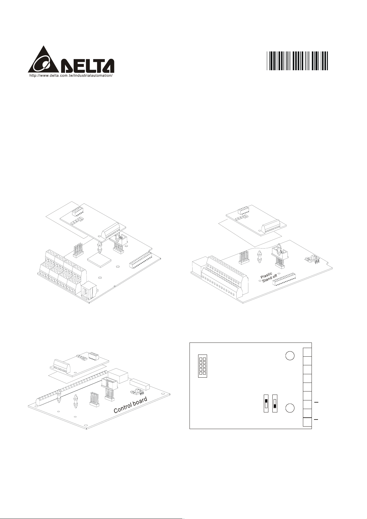
Control Terminals Block Designations
Connect to VFD-B
series control board
PG-02
Select the power
l
o
b
l
o
r
t
n
o
C
Wiring Terminals
FSW2 FSW1
OC
12V
d
r
a
/O
B/O
COM
VP
DCM
A
source and output
of Pulse Generator
TP
5V
B
B
Page 2
2
A
A
A
A
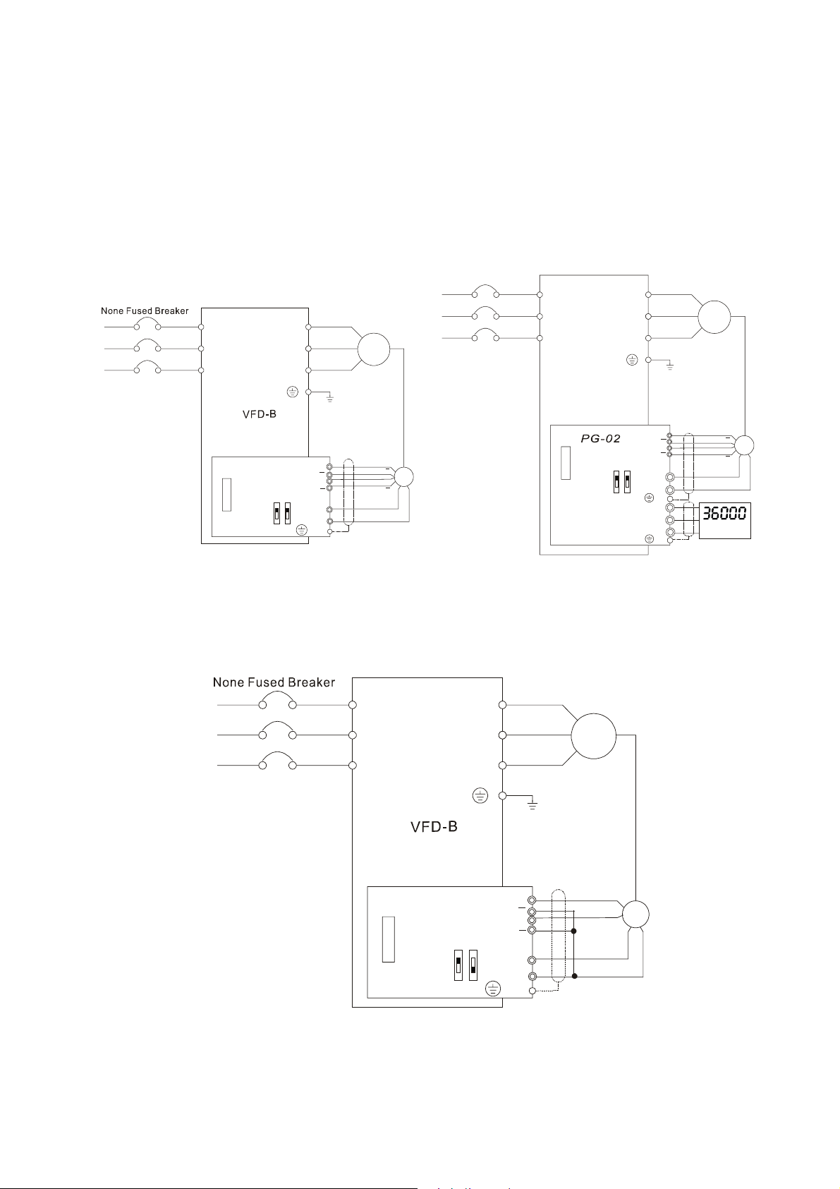
PG Card and Pulse Generator
A. Basic Wiring Diagram
B. Basic Wiring Diagram with RPM
Meter Attached.
None Fused Breaker
R/L1
S/L2
T/L3
NFB
R/L1
S/L2
T/L3
U/T1
V/T2
W/T3
Motor
IM
3~
R/L1
S/L2
T/L3
NFB
R/L1
S/L2
T/L3
U/T1
V/T2
W/T3
Motor
IM
3~
VFD-B
A
B
12V
B
VP
DCM
5VTP
E
A/O
B/O
COM
E
+5V
GND
RPM meter
12V
5V
A
A
B
B
VP
DCM
E
Pulse Generator
Output 12V DC
PG-02
OC
Factory
Default
TP
PG-02 and Pulse Generator Connections
+12V
GND
A
PG
B
B
PG-02 and Pulse Generator Connections
OC
C. When Pulse Generators is Open Collector type, please wire as following.
PG
B
B
R/L1
S/L2
T/L3
NFB
R/L1
S/L2
T/L3
PG-02
Factory
Default
PG-0 2 and Pulse Generator Connections
OC
TP
U/T1
V/T2
W/T3
12V
5V
A
A
B
B
VP
DCM
E
Pulse Generator
Output 12V DC
Motor
IM
3~
+12V
GND
A
PG
B
Page 3

3
PG-02 Terminal Descriptions
Terminals
Terminal Symbols Descriptions
VP
DCM Power source (VP) and input signal (A, B) common
A/O, B/O
COM PG-02 output signal (A/O, B/O) common.
Power source of PG-02 (FSW1 can be switched to 12V or 5V)
Output Voltage: (+12VDC ±5% 200mA) or (+5VDC ±2% 400mA)
Input signal from Pulse Generator. Input type is selected by FSW2.
Maximum 500KP/Sec
PG-02 output signal for use with RPM Meter.
Maximum DC24V 300mA
Wiring Notes
The control, power supply and motor leads must be laid separately. They
must not be fed through the same cable conduit / trunking.
1. Please use a shield cable to prevent interference. Do not run control wire parallel to any
high voltage AC power line (220 V and up).
2. Connect shielded wire to E only.
3. Recommended wire size 0.21 to 0.81mm
4. Wire length:
Types of Pulse
Maximum Wire Length Wire Gauge
Generators
Output Voltage 50m
Open Collector 50m
Line Driver 300m
Complementary 70m
2
(AWG24 to AWG18).
1.25mm2 (AWG16) or above
Page 4

4
5
5
5
5
Types of Pulse Generators
Types of Pulse Generators
FSW1 and FSW2 switches
5V
12V
VCC
Output Voltage
VCC
Open collector
Line driver
VCC
O/P
0V
O/P
0V
Q
Q
FSW2 FSW1
OC
12V
V
TP
FSW2 FSW1
OC
12V
5V
TP
FSW2 FSW1
OC
TP
12V
V
FSW2 FSW1
OC
12V
5V
TP
FSW2 FSW1
OC
TP
12V
V
FSW2 FSW1
OC
12V
5V
TP
Complimentary
ASIA
DELTA ELECTRONICS, INC.
TAOYUAN Plant/
31-1, SHIEN PAN ROAD,
KUEI SAN INDUSTRIAL ZONE
TAOYUAN 333
TEL: 886-3-362-6301
FAX: 886-3-362-7267
FSW2 FSW1
OC
O/P
TP
0V
NORTH/SOUTH AMERICA
DELTA PRODUCTS
CORPORATION
Sales Office/
P.O. BOX 12173
5101 DAVIS DRIVE
RTP, NC 27709 U. S. A.
TEL: 1-919-767-3813
FAX: 1-919-767-3969
12V
FSW2 FSW1
OC
12V
V
TP
5V
EUROPE
DELTRONICS (Netherlands) B.V.
Sales Office/
Industriegebied Venlo Nr. 9031
Columbusweg 20
NL-5928 LC Venlo
The Netherlands
TEL: 31-77-324-1930
FAX: 31-77-324-1931
 Loading...