

Page 1

DELTA ELECTRONICS CO., LTD.
PCI-DMC-A01
PCI-DMC-B01
High-Speed PCI 12-Axis Motion Control Card
Programming Manual
Version: 1.11.1
Page 2

Page 3

PCI-DMC-A01 / PCI-DMC-B01 Programming Manual
About this Manual
User Information
Please keep this manual in a safe place.
This manual is subject to change without notice due to the release of new products,
improvements and changes in technologies, and/or modifications to data and forms.
This manual may not be copied or reproduced in whole or in part without the express written
consent of Delta Electronics.
Trademarks
Windows NT/2000/XP, Visual Studio, Visual C++, Visual BASIC are all registered trademarks of
Microsoft Corporation.
BCB (Borland C++ Builder) is a registered trademark of Borland Corporation.
The names of other products are only used for identification purposes and the registered
trademarks remain the property of their respective owners.
Technical Support and Service
If you require technical support, service, or other information, or should you have any questions
about the use of this product, please visit our website
(http://www.delta.com.tw/industrialautomation) or contact us directly. We look forward to providing
you the best possible support and service. Our contact details are provided below.
ASIA
DELTA ELECTRONICS, INC.
Taoyuan Plant 1
31-1, XINGBANG ROAD,
GUISHAN INDUSTRIAL ZONE,
TAOYUAN COUNTY 33370, TAIWAN, R.O.C.
TEL: 886-3-362-6301
FAX: 886-3-362-7267
NORTH/SOUTH AMERICA
DELTA PRODUCTS CORPORATION (USA)
Raleigh Office
P.O. BOX 12173
5101 DAVIS DRIVE,
RESEARCH TRIANGLE PARK, NC 27709, U.S.A.
TEL: 1-919-767-3813
FAX: 1-919-767-3969
JAPAN
DELTA ELECTRONICS (JAPAN), INC.
Tokyo Office
DELTA SHIBADAIMON BUILDING
2-1-14 SHIBADAIMON, MINATO-KU,
TOKYO, 105-0012, JAPAN
TEL: 81-3-5733-1111
FAX: 81-3-5733-1211
EUROPE
DELTRONICS (THE NETHERLANDS) B.V.
Eindhoven Office
DE WITBOGT 15, 5652 AG EINDHOVEN,
THE NETHERLANDS
TEL: 31-40-259-2850
FAX: 31-40-259-2851
Revised March, 2012 i
Page 4

PCI-DMC-A01 / PCI-DMC-B01 Programming Manual
Table of Contents
Chapter 1 Introduction to the API Function Library --------------------------------------------------- 1-1
1.1 Using the Function Libraries ---------------------------------------------------------------------- 1-1
1.2 Edit New Project ------------------------------------------------------------------------------------- 1-1
1.2.1 Using VC ----------------------------------------------------------------------------------- 1-1
1.2.2 Using Borland C -------------------------------------------------------------------------- 1-1
1.2.3 Using VB ------------------------------------------------------------------------------------ 1-2
1.2.4 Using Delphi ------------------------------------------------------------------------------- 1-2
1.2.5 Using VB.Net ------------------------------------------------------------------------------ 1-2
1.2.6 Using C# ------------------------------------------------------------------------------------ 1-2
Chapter 2 Command Return Values and Messages --------------------------------------------------- 2-1
2.1 Error Codes ------------------------------------------------------------------------------------------- 2-1
2.2 Error Code Example -------------------------------------------------------------------------------- 2-4
Chapter 3 Operating Principles ------------------------------------------------------------------------------- 3-1
3.1 Card Initialization ------------------------------------------------------------------------------------ 3-1
3.1.1 Function List ------------------------------------------------------------------------------- 3-1
3.1.2 Sample Application ----------------------------------------------------------------------- 3-1
3.2 Read/Write Driver Parameters ------------------------------------------------------------------- 3-4
3.2.1 Function List ------------------------------------------------------------------------------- 3-4
3.2.2 Sample Application ----------------------------------------------------------------------- 3-4
3.3 CANopen Protocol ---------------------------------------------------------------------------------- 3-7
3.3.1 Function List ------------------------------------------------------------------------------- 3-7
3.3.2 Sample Application ----------------------------------------------------------------------- 3-7
3.4 Homing Motion Control ---------------------------------------------------------------------------- 3-9
3.4.1 Overview ------------------------------------------------------------------------------------ 3-9
3.4.2 Function List ------------------------------------------------------------------------------ 3-10
3.4.3 Sample Application ---------------------------------------------------------------------- 3-10
3.5 Torque Motion Control ---------------------------------------------------------------------------- 3-13
3.5.1 Function List ------------------------------------------------------------------------------ 3-13
3.5.2 Sample Application ---------------------------------------------------------------------- 3-13
3.6 Velocity Motion Control (1) ----------------------------------------------------------------------- 3-16
3.6.1 Function List ------------------------------------------------------------------------------ 3-16
3.6.2 Sample Application ---------------------------------------------------------------------- 3-16
ii Revised March, 2012
Page 5

PCI-DMC-A01 / PCI-DMC-B01 Programming Manual
3.7 Velocity Motion Control (2) ----------------------------------------------------------------------- 3-19
3.7.1 Function List ------------------------------------------------------------------------------ 3-19
3.7.2 Sample Application ---------------------------------------------------------------------- 3-19
3.8 Point to Point Motion Control -------------------------------------------------------------------- 3-21
3.8.1 Overview ----------------------------------------------------------------------------------- 3-21
3.8.2 Function List ------------------------------------------------------------------------------ 3-21
3.8.3 Sample Application ---------------------------------------------------------------------- 3-22
3.9 Linear Interpolation Motion Control ------------------------------------------------------------ 3-26
3.9.1 Overview ----------------------------------------------------------------------------------- 3-26
3.9.2 Function List ------------------------------------------------------------------------------ 3-26
3.9.3 Sample Application ---------------------------------------------------------------------- 3-27
3.10 Arc Interpolation Motion Control ---------------------------------------------------------------- 3-31
3.10.1 Overview ----------------------------------------------------------------------------------- 3-31
3.10.2 Function List ------------------------------------------------------------------------------ 3-31
3.10.3 Sample Application ---------------------------------------------------------------------- 3-32
3.11 Spiral Interpolation Motion Control -Helix ---------------------------------------------------- 3-37
3.11.1 Function List ------------------------------------------------------------------------------ 3-37
3.11.2 Sample Application ---------------------------------------------------------------------- 3-37
3.12 Continuous Interpolation Motion Control ----------------------------------------------------- 3-42
3.12.1 Overview ----------------------------------------------------------------------------------- 3-42
3.12.2 Function List ------------------------------------------------------------------------------ 3-42
3.12.3 Sample Application ---------------------------------------------------------------------- 3-43
3.13 Software Limit Control ---------------------------------------------------------------------------- 3-47
3.13.1 Function List ------------------------------------------------------------------------------ 3-47
3.13.2 Sample Application ---------------------------------------------------------------------- 3-47
3.14 Synchronization Motion Control ---------------------------------------------------------------- 3-51
3.14.1 Function List ------------------------------------------------------------------------------ 3-51
3.14.2 Sample Application ---------------------------------------------------------------------- 3-51
3.15 Dwell Command ------------------------------------------------------------------------------------ 3-55
3.15.1 Function List ------------------------------------------------------------------------------ 3-55
3.15.2 Sample Application ---------------------------------------------------------------------- 3-55
3.16 Change Position ------------------------------------------------------------------------------------ 3-57
3.16.1 Function List ------------------------------------------------------------------------------ 3-57
3.16.2 Sample Application ---------------------------------------------------------------------- 3-57
3.17 Change Position ------------------------------------------------------------------------------------ 3-60
3.17.1 Function List ------------------------------------------------------------------------------ 3-60
3.17.2 Sample Application ---------------------------------------------------------------------- 3-60
Revised March, 2012 iii
Page 6

PCI-DMC-A01 / PCI-DMC-B01 Programming Manual
3.18 Change Velocity ------------------------------------------------------------------------------------ 3-63
3.18.1 Function List ------------------------------------------------------------------------------ 3-63
3.18.2 Sample Application ---------------------------------------------------------------------- 3-63
3.19 Remote I/O Module-I/O Port --------------------------------------------------------------------- 3-67
3.19.1 Function List ------------------------------------------------------------------------------ 3-67
3.19.2 Sample Application ---------------------------------------------------------------------- 3-67
3.20 Remote I/O Module- Manual Pulse Generator (1) ----------------------------------------- 3-70
3.20.1 Function List ------------------------------------------------------------------------------ 3-70
3.20.2 Sample Application ---------------------------------------------------------------------- 3-70
3.21 Remote I/O Module- Manual Pulse Generator (2) ----------------------------------------- 3-73
3.21.1 Function List ------------------------------------------------------------------------------ 3-73
3.21.2 Sample Application ---------------------------------------------------------------------- 3-73
3.22 Remote Pulse Interface Module -Mode 1 ---------------------------------------------------- 3-76
3.22.1 Function List ------------------------------------------------------------------------------ 3-76
3.22.2 Sample Application ---------------------------------------------------------------------- 3-77
3.23 Remote Pulse Interface Module -Mode 2 ---------------------------------------------------- 3-83
3.23.1 Function List ------------------------------------------------------------------------------ 3-83
3.23.2 Sample Application ---------------------------------------------------------------------- 3-83
3.24 Get (Calculate) Arc Information ----------------------------------------------------------------- 3-87
3.24.1 Function List ------------------------------------------------------------------------------ 3-87
3.24.2 Sample Application ---------------------------------------------------------------------- 3-87
3.25 Control Interrupt ------------------------------------------------------------------------------------ 3-90
3.25.1 Function List ------------------------------------------------------------------------------ 3-90
3.25.2 Sample Application ---------------------------------------------------------------------- 3-90
3.26 MasterCard Security------------------------------------------------------------------------------- 3-94
3.26.1 Function List ------------------------------------------------------------------------------ 3-94
3.26.2 Sample Application ---------------------------------------------------------------------- 3-95
3.27 Remote Analog Input/Output Module ------------------------------------------------------- 3-100
3.27.1 Function List ---------------------------------------------------------------------------- 3-100
3.27.2 Sample Application -------------------------------------------------------------------- 3-101
3.28 Spiral Interpolation Motion Control -Spiral ------------------------------------------------- 3-106
3.28.1 Function List ---------------------------------------------------------------------------- 3-106
3.28.2 Sample Application -------------------------------------------------------------------- 3-106
3.29 Position Compare -------------------------------------------------------------------------------- 3-111
3.29.1 Function List ---------------------------------------------------------------------------- 3-111
3.29.2 Sample Application -------------------------------------------------------------------- 3-112
iv Revised March, 2012
Page 7

PCI-DMC-A01 / PCI-DMC-B01 Programming Manual
3.30 Axis Group ----------------------------------------------------------------------------------------- 3-116
3.30.1 Function List ---------------------------------------------------------------------------- 3-116
3.30.2 Sample Application -------------------------------------------------------------------- 3-116
3.31 Speed Continue ---------------------------------------------------------------------------------- 3-119
3.31.1 Function List ---------------------------------------------------------------------------- 3-119
3.31.2 Sample Application -------------------------------------------------------------------- 3-119
3.32 Spiral Interpolation - Helix Using -Sp1_ Normal Follow -------------------------------- 3-122
3.32.1 Function List ---------------------------------------------------------------------------- 3-122
3.32.2 Sample Application -------------------------------------------------------------------- 3-122
3.33 Logger ---------------------------------------------------------------------------------------------- 3-130
3.33.1 Function List ---------------------------------------------------------------------------- 3-130
3.33.2 Sample Application -------------------------------------------------------------------- 3-130
Chapter 4 Control API -------------------------------------------------------------------------------------------- 4-1
4.1 Data Type and Range ----------------------------------------------------------------------------- 4-1
4.2 Function Description ------------------------------------------------------------------------------- 4-2
Chapter 5 Hardware Initialization API ---------------------------------------------------------------------- 5-1
5.1 _DMC_01_open ------------------------------------------------------------------------------------- 5-2
5.2 _DMC_01_close ------------------------------------------------------------------------------------- 5-2
5.3 _DMC_01_get_CardNo_seq --------------------------------------------------------------------- 5-3
5.4 _DMC_01_pci_initial ------------------------------------------------------------------------------- 5-4
5.5 _DMC_01_get_card_version --------------------------------------------------------------------- 5-4
Chapter 6 Interface API ------------------------------------------------------------------------------------------ 6-1
6.1 _DMC_01_initial_bus ------------------------------------------------------------------------------ 6-2
6.2 _DMC_01_start_ring ------------------------------------------------------------------------------- 6-2
6.3 _DMC_01_get_device_table --------------------------------------------------------------------- 6-3
6.4 _DMC_01_get_node_table ----------------------------------------------------------------------- 6-3
6.5 _DMC_01_check_card_running ----------------------------------------------------------------- 6-4
6.6 _DMC_01_reset_card ----------------------------------------------------------------------------- 6-4
6.7 _DMC_01_check_nodeno ------------------------------------------------------------------------ 6-5
6.8 _DMC_01_get_master_connect_status ------------------------------------------------------- 6-6
6.9 _DMC_01_get_mailbox_Error ------------------------------------------------------------------- 6-6
6.10 _DMC_01_get_mailbox_cnt ---------------------------------------------------------------------- 6-7
6.11 _DMC_01_get_dsp_cnt --------------------------------------------------------------------------- 6-7
6.12 _DMC_01_set_dio_output ------------------------------------------------------------------------ 6-8
6.13 _DMC_01_get_dio_output ------------------------------------------------------------------------ 6-8
Revised March, 2012 v
Page 8

PCI-DMC-A01 / PCI-DMC-B01 Programming Manual
6.14 _DMC_01_get_dio_input -------------------------------------------------------------------------- 6-9
6.15 _DMC_01_get_cycle_time ------------------------------------------------------------------------ 6-9
6.16 _DMC_01_initial_bus2 ---------------------------------------------------------------------------- 6-10
6.17 _DMC_01_motion_cnt ---------------------------------------------------------------------------- 6-10
Chapter 7 Servo Drive Parameter Read/Write API ------------------------------------------------------ 7-1
7.1 _DMC_01_read_servo_parameter ------------------------------------------------------------- 7-2
7.2 _DMC_01_write_servo_parameter ------------------------------------------------------------- 7-3
Chapter 8 Using SDO Protocol API -------------------------------------------------------------------------- 8-1
8.1 CANopen SDO protocol --------------------------------------------------------------------------- 8-2
8.2 _DMC_01_check_canopen_lock ---------------------------------------------------------------- 8-6
8.3 _DMC_01_get_canopen_ret --------------------------------------------------------------------- 8-7
8.4 _DMC_01_set_pdo_mode ------------------------------------------------------------------------ 8-8
8.5 _DMC_01_send_message ----------------------------------------------------------------------- 8-9
8.6 _DMC_01_send_message3 --------------------------------------------------------------------- 8-10
8.7 _DMC_01_read_message ----------------------------------------------------------------------- 8-11
8.8 _DMC_01_read_message2 --------------------------------------------------------------------- 8-12
8.9 _DMC_01_get_message ------------------------------------------------------------------------- 8-13
8.10 _DMC_01_reset_sdo_choke -------------------------------------------------------------------- 8-14
8.11 _DMC_01_get_sdo_retry_history -------------------------------------------------------------- 8-14
Chapter 9 Point to Point Motion Control Packet Protocol API ------------------------------------- 9-1
9.1 _DMC_01_set_sdo_driver_speed_profile ---------------------------------------------------- 9-2
9.2 _DMC_01_start_sdo_driver_r_move ----------------------------------------------------------- 9-3
9.3 _DMC_01_start_sdo_driver_a_move ---------------------------------------------------------- 9-4
9.4 _DMC_01_start_sdo_driver_new_position_move ------------------------------------------ 9-5
Chapter 10 Homing Motion Control Packet Protocol API ------------------------------------------- 10-1
10.1 _DMC_01_set_home_config -------------------------------------------------------------------- 10-2
10.2 _DMC_01_set_home_move --------------------------------------------------------------------- 10-7
10.3 _DMC_01_escape_home_move --------------------------------------------------------------- 10-8
Chapter 11 Velocity Motion Control Packet Protocol API ------------------------------------------- 11-1
11.1 _DMC_01_set_velocity_mode ------------------------------------------------------------------ 11-2
11.2 _DMC_01_set_velocity --------------------------------------------------------------------------- 11-3
11.3 _DMC_01_set_velocity_stop -------------------------------------------------------------------- 11-4
11.4 _DMC_01_set_velocity_torque_limit ---------------------------------------------------------- 11-5
vi Revised March, 2012
Page 9

PCI-DMC-A01 / PCI-DMC-B01 Programming Manual
Chapter 12 Torque Motion Control Packet Protocol API -------------------------------------------- 12-1
12.1 _DMC_01_set_torque_mode ------------------------------------------------------------------- 12-2
12.2 _DMC_01_set_torque ---------------------------------------------------------------------------- 12-3
12.3 _DMC_01_set_torque_stop --------------------------------------------------------------------- 12-4
12.4 _DMC_01_set_torque_velocity_limit ---------------------------------------------------------- 12-5
Chapter 13 Using PDO Protocol API ----------------------------------------------------------------------- 13-1
13.1 _DMC_01_ipo_set_svon ------------------------------------------------------------------------- 13-2
13.2 _DMC_01_get_buffer_length ------------------------------------------------------------------- 13-3
13.3 _DMC_01_command_buf_clear ---------------------------------------------------------------- 13-4
13.4 _DMC_01_buf_dwell ------------------------------------------------------------------------------ 13-5
13.5 _DMC_01_set_group ----------------------------------------------------------------------------- 13-6
Chapter 14 Stop Motion Control API ----------------------------------------------------------------------- 14-1
14.1 _DMC_01_emg_stop ----------------------------------------------------------------------------- 14-2
14.2 _DMC_01_sd_stop -------------------------------------------------------------------------------- 14-3
14.3 _DMC_01_sd_abort ------------------------------------------------------------------------------- 14-4
14.4 _DMC_01_set_sd_mode ------------------------------------------------------------------------- 14-5
Chapter 15 Motion Status API -------------------------------------------------------------------------------- 15-1
15.1 _DMC_01_motion_done ------------------------------------------------------------------------- 15-2
15.2 _DMC_01_motion_status ------------------------------------------------------------------------ 15-3
Chapter 16 Motion Counter Value API --------------------------------------------------------------------- 16-1
16.1 _DMC_01_get_command ------------------------------------------------------------------------ 16-2
16.2 _DMC_01_set_command ------------------------------------------------------------------------ 16-2
16.3 _DMC_01_get_position--------------------------------------------------------------------------- 16-3
16.4 _DMC_01_set_position --------------------------------------------------------------------------- 16-3
16.5 _DMC_01_get_target_pos ----------------------------------------------------------------------- 16-4
16.6 _DMC_01_get_torque ---------------------------------------------------------------------------- 16-5
16.7 _DMC_01_get_current_speed ------------------------------------------------------------------ 16-6
16.8 _DMC_01_get_current_speed_rpm ----------------------------------------------------------- 16-7
Chapter 17 Software Limit API ------------------------------------------------------------------------------- 17-1
17.1 _DMC_01_set_soft_limit ------------------------------------------------------------------------- 17-2
17.2 _DMC_01_enable_soft_limit -------------------------------------------------------------------- 17-3
17.3 _DMC_01_disable_soft_limit -------------------------------------------------------------------- 17-3
17.4 _DMC_01_get_soft_limit_status --------------------------------------------------------------- 17-4
Revised March, 2012 vii
Page 10

PCI-DMC-A01 / PCI-DMC-B01 Programming Manual
Chapter 18 1-Axis Motion Control API -------------------------------------------------------------------- 18-1
18.1 _DMC_01_start_tr_move ------------------------------------------------------------------------ 18-2
18.2 _DMC_01_start_sr_move ------------------------------------------------------------------------ 18-3
18.3 _DMC_01_start_ta_move ------------------------------------------------------------------------ 18-4
18.4 _DMC_01_start_sa_move ----------------------------------------------------------------------- 18-5
18.5 _DMC_01_p_change ----------------------------------------------------------------------------- 18-6
18.6 _DMC_01_v_change ------------------------------------------------------------------------------ 18-7
18.7 _DMC_01_start_tr_move_2seg ---------------------------------------------------------------- 18-9
18.8 _DMC_01_start_sr_move_2seg -------------------------------------------------------------- 18-11
18.9 _DMC_01_start_ta_move_2seg -------------------------------------------------------------- 18-12
18.10 _DMC_01_start_sa_move_2seg ------------------------------------------------------------- 18-13
18.11 _DMC_01_start_tr_move_2seg2 ------------------------------------------------------------- 18-14
18.12 _DMC_01_start_sr_move_2seg2 ------------------------------------------------------------ 18-16
18.13 _DMC_01_start_ta_move_2seg2 ------------------------------------------------------------ 18-17
18.14 _DMC_01_start_sa_move_2seg2 ----------------------------------------------------------- 18-18
18.15 _DMC_01_feedrate_overwrite ---------------------------------------------------------------- 18-19
18.16 _DMC_01_start_v3_move --------------------------------------------------------------------- 18-21
Chapter 19 2-Axis Linear Interpolation Motion Control API ---------------------------------------- 19-1
19.1 _DMC_01_start_tr_move_xy -------------------------------------------------------------------- 19-2
19.2 _DMC_01_start_sr_move_xy ------------------------------------------------------------------- 19-4
19.3 _DMC_01_start_ta_move_xy ------------------------------------------------------------------- 19-6
19.4 _DMC_01_start_sa_move_xy ------------------------------------------------------------------ 19-8
19.5 _DMC_01_start_v3_move_xy ---------------------------------------------------------------- 19-10
Chapter 20 2-Axis Arc Interpolation Motion Control API -------------------------------------------- 20-1
20.1 _DMC_01_start_tr_arc_xy ----------------------------------------------------------------------- 20-3
20.2 _DMC_01_start_sr_arc_xy ---------------------------------------------------------------------- 20-5
20.3 _DMC_01_start_ta_arc_xy ---------------------------------------------------------------------- 20-7
20.4 _DMC_01_start_sa_arc_xy ---------------------------------------------------------------------- 20-9
20.5 _DMC_01_start_tr_arc2_xy ------------------------------------------------------------------- 20-11
20.6 _DMC_01_start_sr_arc2_xy ------------------------------------------------------------------- 20-13
20.7 _DMC_01_start_ta_arc2_xy ------------------------------------------------------------------- 20-15
20.8 _DMC_01_start_sa_arc2_xy ------------------------------------------------------------------ 20-17
20.9 _DMC_01_start_tr_arc3_xy ------------------------------------------------------------------- 20-19
20.11 _DMC_01_start_ta_arc3_xy ------------------------------------------------------------------- 20-23
20.12 _DMC_01_start_sa_arc3_xy ------------------------------------------------------------------ 20-25
viii Revised March, 2012
Page 11

PCI-DMC-A01 / PCI-DMC-B01 Programming Manual
20.13 _DMC_01_start_spiral_xy --------------------------------------------------------------------- 20-27
20.14 _DMC_01_start_spiral2_xy -------------------------------------------------------------------- 20-29
20.15 _DMC_01_start_v3_arc_xy -------------------------------------------------------------------- 20-31
20.16 _DMC_01_start_v3_arc2_xy ------------------------------------------------------------------ 20-33
20.17 _DMC_01_start_v3_arc3_xy ------------------------------------------------------------------ 20-35
20.18 _DMC_01_start_v3_spiral_xy ----------------------------------------------------------------- 20-37
20.19 _DMC_01_start_v3_spiral2_xy --------------------------------------------------------------- 20-39
Chapter 21 3-Axis Linear Interpolation Motion Control API ---------------------------------------- 21-1
21.1 _DMC_01_start_tr_move_xyz ------------------------------------------------------------------ 21-2
21.2 _DMC_01_start_sr_move_xyz ------------------------------------------------------------------ 21-3
21.3 _DMC_01_start_ta_move_xyz ------------------------------------------------------------------ 21-4
21.4 _DMC_01_start_sa_move_xyz ----------------------------------------------------------------- 21-5
21.5 _DMC_01_start_v3_move_xyz ----------------------------------------------------------------- 21-6
Chapter 22 3-Axis Spiral Interpolation Motion Control API ---------------------------------------- 22-1
22.1 _DMC_01_start_tr_heli_xy ---------------------------------------------------------------------- 22-2
22.2 _DMC_01_start_sr_heli_xy ---------------------------------------------------------------------- 22-4
22.3 _DMC_01_start_ta_heli_xy ---------------------------------------------------------------------- 22-6
22.4 _DMC_01_start_sa_heli_xy --------------------------------------------------------------------- 22-8
22.5 _DMC_01_start_v3_heli_xy ------------------------------------------------------------------- 22-10
Chapter 23 Velocity Motion Control API ------------------------------------------------------------------ 23-1
23.1 _DMC_01_tv_move ------------------------------------------------------------------------------- 23-2
23.2 _DMC_01_sv_move ------------------------------------------------------------------------------- 23-3
Chapter 24 Synchronization Motion Control API ------------------------------------------------------ 24-1
24.1 _DMC_01_sync_move---------------------------------------------------------------------------- 24-2
24.2 _DMC_01_sync_move_config ------------------------------------------------------------------ 24-2
Chapter 25 Remote Module Control API ------------------------------------------------------------------ 25-1
25.1 _DMC_01_get_rm_input_value ---------------------------------------------------------------- 25-2
25.2 _DMC_01_set_rm_input_filter ------------------------------------------------------------------ 25-3
25.3 _DMC_01_set_rm_input_filter_enable ------------------------------------------------------- 25-4
25.4 _DMC_01_set_rm_output_value --------------------------------------------------------------- 25-5
25.5 _DMC_01_set_rm_output_value_error_handle -------------------------------------------- 25-6
25.6 _DMC_01_get_rm_output_value --------------------------------------------------------------- 25-7
25.7 _DMC_01_get_rm_output_value_error_handle -------------------------------------------- 25-8
Revised March, 2012 ix
Page 12

PCI-DMC-A01 / PCI-DMC-B01 Programming Manual
25.8 _DMC_01_set_rm_output_active -------------------------------------------------------------- 25-9
Chapter 26 MPG and JOG Operation API ----------------------------------------------------------------- 26-1
26.1 _DMC_01_set_rm_mpg_axes_enable ------------------------------------------------------- 26-2
26.2 _DMC_01_set_rm_mpg_axes_enable2 ------------------------------------------------------ 26-4
26.3 _DMC_01_set_rm_jog_axes_enable --------------------------------------------------------- 26-6
Chapter 27 4-Channel Pulse Interface API --------------------------------------------------------------- 27-1
27.1 _DMC_01_set_rm_04pi_ipulse_mode -------------------------------------------------------- 27-2
27.2 _DMC_01_set_rm_04pi_opulse_mode ------------------------------------------------------- 27-3
27.3 _DMC_01_set_rm_04pi_svon_polarity ------------------------------------------------------- 27-4
27.4 _DMC_01_set_rm_04pi_DO2 ------------------------------------------------------------------ 27-5
27.5 _DMC_01_set_rm_04pi_homing_ratio ------------------------------------------------------- 27-6
27.6 _DMC_01_04pi_set_poweron ------------------------------------------------------------------ 27-7
27.7 _DMC_01_rm_04PI_get_buffer ---------------------------------------------------------------- 27-8
Chapter 28 4-Channel Pulse Interface (Mode 1) Motion Control API ---------------------------- 28-1
28.1 _DMC_01_rm_04pi_md1_start_move -------------------------------------------------------- 28-3
28.2 _DMC_01_rm_04pi_md1_v_move ------------------------------------------------------------ 28-5
28.3 _DMC_01_rm_04pi_md1_start_line2 --------------------------------------------------------- 28-6
28.4 _DMC_01_rm_04pi_md1_start_line3 --------------------------------------------------------- 28-8
28.5 _DMC_01_rm_04pi_md1_start_line4 ------------------------------------------------------- 28-10
28.6 _DMC_01_rm_04pi_md1_start_arc --------------------------------------------------------- 28-12
28.7 _DMC_01_rm_04pi_md1_start_arc2 ------------------------------------------------------- 28-14
28.8 _DMC_01_rm_04pi_md1_start_arc3 ------------------------------------------------------- 28-16
28.9 _DMC_01_rm_04pi_md1_start_heli --------------------------------------------------------- 28-18
28.10 _DMC_01_rm_04pi_md1_p_change -------------------------------------------------------- 28-20
28.11 _DMC_01_rm_04pi_md1_v_change -------------------------------------------------------- 28-21
28.12 _DMC_01_rm_04pi_md1_set_gear --------------------------------------------------------- 28-22
28.13 _DMC_01_rm_04pi_md1_set_soft_limit --------------------------------------------------- 28-23
28.14 _DMC_01_rm_04pi_md1_get_soft_limit_status ----------------------------------------- 28-24
28.15 _DMC_01_rm_04pi_md1_set_sld ----------------------------------------------------------- 28-25
28.16 _DMC_01_rm_04pi_md1_get_mc_error_code ------------------------------------------- 28-26
28.17 _DMC_01_set_rm_04pi_ref_counter ------------------------------------------------------- 28-27
Chapter 29 4-Channel Analog Output Remote Module API ---------------------------------------- 29-1
29.1 _DMC_01_rm_04da_set_output_value ------------------------------------------------------ 29-2
29.2 _DMC_01_rm_04da_get_output_value ------------------------------------------------------ 29-3
x Revised March, 2012
Page 13

PCI-DMC-A01 / PCI-DMC-B01 Programming Manual
29.3 _DMC_01_rm_04da_get_return_code ------------------------------------------------------- 29-4
29.4 _DMC_01_rm_04da_set_output_range ------------------------------------------------------ 29-5
29.5 _DMC_01_rm_04da_set_output_enable ----------------------------------------------------- 29-6
29.6 _DMC_01_rm_04da_set_output_overrange ------------------------------------------------ 29-7
29.7 _DMC_01_rm_04da_set_output_error_clear ----------------------------------------------- 29-8
29.8 _DMC_01_rm_04da_read_data ---------------------------------------------------------------- 29-9
29.9 _DMC_01_rm_04da_set_output_error_handle ------------------------------------------- 29-10
29.10 _DMC_01_rm_04da_set_output_offset_value ------------------------------------------- 29-11
29.11 _DMC_01_rm_04da_get_output_offset_value ------------------------------------------- 29-12
Chapter 30 4-Channel Analog Input Remote Module API ------------------------------------------- 30-1
30.1 _DMC_01_set_04ad_input_range ------------------------------------------------------------- 30-2
30.2 _DMC_01_get_04ad_input_range ------------------------------------------------------------- 30-3
30.3 _DMC_01_set_04ad_zero_scale -------------------------------------------------------------- 30-4
30.4 _DMC_01_get_04ad_zero_scale_status ---------------------------------------------------- 30-5
30.5 _DMC_01_set_04ad_full_scale ---------------------------------------------------------------- 30-6
30.6 _DMC_01_get_04ad_full_scale_status ------------------------------------------------------ 30-7
30.7 _DMC_01_set_04ad_conversion_time ------------------------------------------------------- 30-8
30.8 _DMC_01_get_04ad_conversion_time ------------------------------------------------------- 30-9
30.9 _DMC_01_get_04ad_data --------------------------------------------------------------------- 30-10
30.10 _DMC_01_set_04ad_average_mode ------------------------------------------------------- 30-11
30.11 _DMC_01_get_04ad_average_mode ------------------------------------------------------- 30-12
30.12 _DMC_01_set_04ad_input_enable ---------------------------------------------------------- 30-13
Chapter 31 Slave Data API ------------------------------------------------------------------------------------ 31-1
31.1 _DMC_01_get_devicetype ----------------------------------------------------------------------- 31-2
31.2 _DMC_01_get_slave_version ------------------------------------------------------------------- 31-4
Chapter 32 Parameter Monitoring API --------------------------------------------------------------------- 32-1
32.1 _DMC_01_set_monitor --------------------------------------------------------------------------- 32-2
32.2 _DMC_01_get_monitor --------------------------------------------------------------------------- 32-5
32.3 _DMC_01_get_servo_command --------------------------------------------------------------- 32-6
32.4 _DMC_01_get_servo_DI ------------------------------------------------------------------------- 32-7
32.5 _DMC_01_get_servo_DO ----------------------------------------------------------------------- 32-8
Chapter 33 Alarm Message API ------------------------------------------------------------------------------ 33-1
33.1 _DMC_01_set_ralm ------------------------------------------------------------------------------- 33-2
33.2 _DMC_01_get_alm_code ------------------------------------------------------------------------ 33-3
Revised March, 2012 xi
Page 14

PCI-DMC-A01 / PCI-DMC-B01 Programming Manual
33.3 _DMC_01_master_alm_code ------------------------------------------------------------------- 33-4
33.4 _DMC_01_slave_error ---------------------------------------------------------------------------- 33-5
Chapter 34 Multi-Axis Motion Control API --------------------------------------------------------------- 34-1
34.1 _DMC_01_multi_axes_move ------------------------------------------------------------------- 34-2
34.2 _ DMC_01_liner_speed_master ---------------------------------------------------------------- 34-4
34.3 _DMC_01_start_v3_multi_axes ---------------------------------------------------------------- 34-5
Chapter 35 Buffer Operation API ---------------------------------------------------------------------------- 35-1
35.1 _DMC_01_set_trigger_buf_function ----------------------------------------------------------- 35-2
Chapter 36 Interrupt API --------------------------------------------------------------------------------------- 36-1
36.1 _DMC_01_ set_int_factor ------------------------------------------------------------------------ 36-2
36.2 _DMC_01_ int_enable ---------------------------------------------------------------------------- 36-3
36.3 _DMC_01_ int_disable --------------------------------------------------------------------------- 36-3
36.4 _DMC_01_ get_int_count ------------------------------------------------------------------------ 36-4
36.5 _DMC_01_ get_int_status ----------------------------------------------------------------------- 36-5
36.6 _DMC_01_link_ interrupt ------------------------------------------------------------------------- 36-6
Chapter 37 Security API ---------------------------------------------------------------------------------------- 37-1
37.1 _DMC_01_ read_security ------------------------------------------------------------------------ 37-2
37.2 _DMC_01_ read_security_status -------------------------------------------------------------- 37-2
37.3 _DMC_01_write_security ------------------------------------------------------------------------ 37-3
37.4 _DMC_01_ write_security_status -------------------------------------------------------------- 37-3
37.5 _DMC_01_ check_userpassword -------------------------------------------------------------- 37-4
37.6 _DMC_01_write_ userpassword --------------------------------------------------------------- 37-4
37.7 _DMC_01_check_verifykey --------------------------------------------------------------------- 37-5
37.8 _DMC_01_write_verifykey ----------------------------------------------------------------------- 37-5
37.9 _DMC_01_ read_serialno ------------------------------------------------------------------------ 37-6
37.10 misc_slave_check_userpassword ------------------------------------------------------------- 37-7
37.11 _misc_slave_write_userpassword ------------------------------------------------------------- 37-8
37.12 _misc_slave_get_serialno ----------------------------------------------------------------------- 37-9
37.13 _misc_security ------------------------------------------------------------------------------------ 37-10
37.14 _misc_slave_write_verifykey ------------------------------------------------------------------ 37-11
37.15 _misc_slave_check_verifykey ---------------------------------------------------------------- 37-12
37.16 _misc_slave_user_data_buffer_read ------------------------------------------------------- 37-13
37.17 _misc_slave_user_data_buffer_write ------------------------------------------------------- 37-14
37.18 _misc_slave_user_data_to_flash ------------------------------------------------------------ 37-15
xii Revised March, 2012
Page 15

PCI-DMC-A01 / PCI-DMC-B01 Programming Manual
Chapter 38 Limit Reversal API ------------------------------------------------------------------------------- 38-1
38.1 _ DMC_01_rm_04pi_set_MEL_polarity ------------------------------------------------------ 38-2
38.2 _ DMC_01_rm_04pi_get_MEL_polarity ------------------------------------------------------ 38-3
38.3 _ DMC_01_rm_04pi_set_PEL_polarity ------------------------------------------------------- 38-4
38.4 _ DMC_01_rm_04pi_get_PEL_polarity ------------------------------------------------------- 38-5
Chapter 39 Compare API --------------------------------------------------------------------------------------- 39-1
39.1 _ DMC_01_set_compare_channel_position ------------------------------------------------ 39-2
39.2 _DMC_01_get_compare_channel_position ------------------------------------------------- 39-3
39.3 _DMC_01_set_compare_ipulse_mode ------------------------------------------------------- 39-4
39.4 _DMC_01_set_compare_channel_direction ------------------------------------------------ 39-5
39.5 _DMC_01_set_compare_channel_trigger_time -------------------------------------------- 39-6
39.6 _DMC_01_set_compare_channel_one_shot ----------------------------------------------- 39-7
39.7 _DMC_01_set_compare_channel_source --------------------------------------------------- 39-8
39.8 _DMC_01_channel0_position_cmp ----------------------------------------------------------- 39-9
39.9 _DMC_01_channel1_output_enable -------------------------------------------------------- 39-10
39.10 _DMC_01_channel1_output_mode --------------------------------------------------------- 39-11
39.11 _DMC_01_channel1_get_io_status --------------------------------------------------------- 39-13
39.12 _DMC_01_channel1_set_gpio_out ---------------------------------------------------------- 39-14
39.13 _DMC_01_channel1_position_compare_table ------------------------------------------- 39-15
39.14 _DMC_01_channel1_position_compare_table_level ----------------------------------- 39-16
39.15 _DMC_01_channel1_position_compare_table_cnt ------------------------------------- 39-17
39.16 _DMC_01_set_compare_channel_polarity ------------------------------------------------ 39-18
39.17 _DMC_01_channel0_position_cmp_by_gpio --------------------------------------------- 39-19
39.18 _DMC_01_channel1_position_re_compare_table --------------------------------------- 39-20
39.19 _DMC_01_channel1_position_re_compare_table_level ------------------------------- 39-20
Chapter 40 Linear and Arc Interpolation Motion Control API -------------------------------------- 40-1
40.1 _DMC_01_start_rline_xy ------------------------------------------------------------------------- 40-2
40.2 _DMC_01_start_rline_xyz ----------------------------------------------------------------------- 40-4
40.4 _DMC_01_start_v3_rline_xyz ------------------------------------------------------------------- 40-9
Chapter 41 Speed Continue API ----------------------------------------------------------------------------- 41-1
41.1 _DMC_01_speed_continue---------------------------------------------------------------------- 41-2
41.2 _DMC_01_speed_continue_mode ------------------------------------------------------------ 41-3
41.3 _DMC_01_speed_continue_combine_ratio ------------------------------------------------- 41-5
Revised March, 2012 xiii
Page 16

PCI-DMC-A01 / PCI-DMC-B01 Programming Manual
Chapter 42 Other API -------------------------------------------------------------------------------------------- 42-1
42.1 _misc_app_get_circle_endpoint ---------------------------------------------------------------- 42-2
42.2 _misc_app_get_circle_center_point ----------------------------------------------------------- 42-3
42.3 _misc_set_record_debuging -------------------------------------------------------------------- 42-4
42.4 _misc_open_record_debuging_file ------------------------------------------------------------ 42-4
42.5 _DMC_01_enable_dda_mode ------------------------------------------------------------------ 42-5
42.6 _DMC_01_set_dda_data------------------------------------------------------------------------- 42-6
42.7 _DMC_01_get_dda_cnt -------------------------------------------------------------------------- 42-6
xiv Revised March, 2012
Page 17

Chapter 1 Introduction to the API Function Library | PCI-DMC-A01 / PCI-DMC-B01
Chapter 1 Introduction to the
API Function Library
PCI-DMC-A01 provides a function library and dynamic-link library (DLL) which can be called upon
to perform functions as you require. The following sections will detail how you can incorporate
these function libraries into your development environment.
1.1 Using the Function Libraries
Once you have installed the program you will find two libraries under the “lib” folder. These
libraries are intended for use in Visual Studio C or Borland development environments.
Table 1.1
PCI_DMC_01.lib Visual Studio C function
BCBPCI_DMC_01.lib Borland C function
1.2 Edit New Project
1.2.1 Using VC
1. Add the following command to your project:
# include “..\inc\VC\PCI_DMC_01.h”
# include “..\inc\VC\PCI_DMC_01_Err.h”
2. Under the Visual C development environment, select Project / Setting / Link
Under Object / Library modules, input “..\lib\PCI_DMC_01.lib”
3. Once set, you can begin using the API to control PCI-DMC-A01.
library
library
1.2.2 Using Borland C
1. Add the following command to your project:
# include “..\inc\BCB \PCI_DMC_01.h”
# include “..\inc\BCB\PCI_DMC_01_Err.h”
Revised March, 2012 1-1
Page 18

Chapter 1 Introduction to the API Function Library | PCI-DMC-A01 / PCI-DMC-B01
2. Under the Borland C++ Build development environment, select View/ Project
Manager
Add the function library “..\lib\BCBPCI_DMC_01.lib” to your new project.
3. Once set, you can begin using the API to control PCI-DMC-A01.
1.2.3 Using VB
Under the installation directory “..\ \PCI-DMC-A01\inc\VB” you will find
“PCI_DMC_01.bas” and “PCI_DMC_01_Err.bas”. Add these two files to your new
project to use the API to control PCI-DMC-A01.
1.2.4 Using Delphi
Under the installation directory “..\ \PCI-DMC-A01\inc\Delphi” you will find
“PCI_DMC_01.pas”. Add this file to your new project to use the API to control
PCI-DMC-A01.
1.2.5 Using VB.Net
Under the installation directory “..\ \PCI-DMC-A01\inc\VB.Net” you will find
“PCI_DMC_01.vb” and “PCI_DMC_01_ERR.vb”. Add these two files to your new
project to use the API to control PCI-DMC-A01.
1.2.6 Using C#
In the installation directory “..\ \PCI-DMC-A01\inc\C#” you will find “PCI_DMC_01.css”
and “PCI_DMC_01_ERR.cs”. Add these two files to your new project to use the API to
control PCI-DMC-A01.
1-2 Revised March, 2012
Page 19

Chapter 2 Command Return Values and Messages | PCI-DMC-A01 / PCI-DMC-B01
Chapter 2 Command Return Values
2.1 Error Codes
When you use API for PCI-DMC-A01, the function library will generally return one of the
error codes listed in Table 2.1.
If the API function's return value is 0, then the API function was executed successfully. If
the API function returns some other error code, then an error may have occurred during
operation or in the hardware connection. You can troubleshoot the problem by referring to
the error code description.
and Messages
Table 2.1
Error Return
Code
(Decimal)
0 ERR_NoError API executed successfully
3 ERR_CardNoError
5 ERR_bootmodeErr Unable to boot DSP procedure
6 ERR_downloadcode DSP memory program read/write error
7 ERR_downloadinit DSP memory data read/write error
8 ERR_PCI_boot_first
11 ERR_AxisNoError Axis number error (too large)
12 ERR_IPO_First Must be in IPO mode
13 ERR_Target_reach Target must be in position for Mode 1 operation
14 ERR_Servo_on_first Must be set to Servo on
15 ERR_MPG_Mode
Error Code Error Description
Card number error. Please check the number set
by the DIP Switch on the card.
“_DMC_01_pci_initial” AP function must be
launched first
Unable to clear position in Manual Pulse
Generator (MPG) mode
16 ERR_PDO_TG
17 ERR_ConfigFileOpenError Error opening configuration file
18 ERR_Ctrl_value Command code error
19 ERR_Security_Fifo Write error using Security Fpga
20 ERR_Security_Fifo_busy Security Fpga is busy
Revised March, 2012 2-1
Unable to return acknowledgement when sending
command to module in PDO mode
Page 20

Chapter 2 Command Return Values and Messages | PCI-DMC-A01 / PCI-DMC-B01
Error Return
Code
Error Code Error Description
(Decimal)
21 ERR_SpeedLimitError Defined velocity exceeds maximum velocity
22 ERR_Security_Page Security page must be smaller than 16
23 ERR_Slave_Security_op Security slave_operate command failed
24 ERR_channel_no channel no error
“_DMC_01_pci_initial” AP function must be
25 ERR_start_ring_first
launched first
26 ERR_NodeIDError NodeID does not exist
27 ERR_MailBoxErr DSP busy, unable to send command
28 ERR_SdoData SDO data sent, but no response received
29 ERR_IOCTL Operating system unable to process this IRP
30 ERR_SdoSvonFirst Servo On required to use SDO axis control
31 ERR_SlotIDError No such Slot ID for Slave module (GA or RM)
32 ERR_PDO_First PDO protocol mode required to use PDO protocol
33 ERR_Protocal_build Protocol, not built
34 ERR_Maching_TimeOut Module matching time-out
35 ERR_Maching_NG Module matching failed
40 ERR_Master_Security_Wr Security Master Write command failed
41 ERR_Master_Security_Rd Security Master Read command failed
42 ERR_Master_Security_Pw Correct password required
Master Card version error. Please contact
50 ERR_NonSupport_CardVer
distributor to purchase the correct Master Card
51 ERR_Compare_Source Ver Type: B Compare Source selection error
Compare direction error; dir must be set to 1 or 0
52 ERR_Compare_Direction
(1:ccw, 0:cw)
112 ERR_RangeError Axis number error
114 ERR_MotionBusy Motion command overlap
116 ERR_SpeedError Maximum velocity set to 0
ERR_AccTimeError Acceleration/deceleration time greater than 1000
117
sec
124 ERR_PitchZero Screw displacement parameter “pitch” set to 0
127 ERR_BufferFull Motion command buffer is full
128 ERR_PathError Motion command error
130 ERR_NoSupportMode Velocity change not supported
ERR_FeedHold_support Feedhold Stop enabled. Unable to receive new
132
commands
2-2 Revised March, 2012
Page 21

Error Return
Chapter 2 Command Return Values and Messages | PCI-DMC-A01 / PCI-DMC-B01
Code
Error Code Error Description
(Decimal)
ERR_SDStop_On Currently executing deceleration/stop command,
133
Unable to receive new commands
ERR_VelChange_supper Unable to execute velocity change function
134
(Feedhold, Synch, and Deceleration)
135 ERR_Command_set Unable to repeat FeedHold command
ERR_sdo_message_choke Sdo command return error. Please check
136
network connection
ERR_VelChange_buff_feedh
Feedhold function must be enabled first. Unable
137
old
to change velocity
ERR_VelChange_sync_move Waiting for sync command, unable to change
138
velocity
ERR_VelChange_SD_On Waiting for decelerate command, unable to
139
change velocity
ERR_P_Change_Mode Single axis point to point mode. Acceleration
140
segment's velocity is 0. Non-single axis point to
point mode
When mode is
_Path_p_change,_Path_velocity_change_onfly,
141 ERR_BufferLength
_Path_Start_Move_2seg then Buffer Length
must be 0
142 ERR_2segMove_Dist Distance must be in same direction
143 ERR_CenterMatch Center must match
144 ERR_EndMatch Center must match
145 ERR_AngleCalcu Angle calculation error
146 ERR_RedCalcu Radius calculation error
147 ERR_GearSetting Gear numerator or denominator is 0
Table Setting First Array Point Error, Table
148 ERR_CamTable
setting cannot be negative; table[-1] does not
exist
ERR_AxesNum Number of axes must be set to at least 2 for
149
multiple axes settings
150 ERR_SpiralPos Final position will be the center of the spiral
Revised March, 2012 2-3
Page 22

Chapter 2 Command Return Values and Messages | PCI-DMC-A01 / PCI-DMC-B01
2.2 Error Code Example
The following example is a return function. You can use it as a reference to create new
functions that meet your control requirements.
Example
Void error (unsigned short rc) // Function that returns error code; rc is the parsed return
value
{
Switch(rc)
{
Case 3:
printf(“Card No. Error, Please check Card No. again.”);
break;
default:
break;
}
2-4 Revised March, 2012
Page 23
Chapter 3 Operating Principles
3.1 Card Initialization
3.1.1 Function List
_DMC_01_open
_DMC_01_get_CardNo_seq
_DMC_01_check_card_running
_DMC_01_reset_card
_DMC_01_close
Chapter 3 Operating Principles | PCI-DMC-A01 / PCI-DMC-B01
Table 3.1
Function Name
_DMC_01_pci_initial
_DMC_01_initial_bus
_DMC_01_start_ring
_DMC_01_get_device_table
_DMC_01_get_node_table
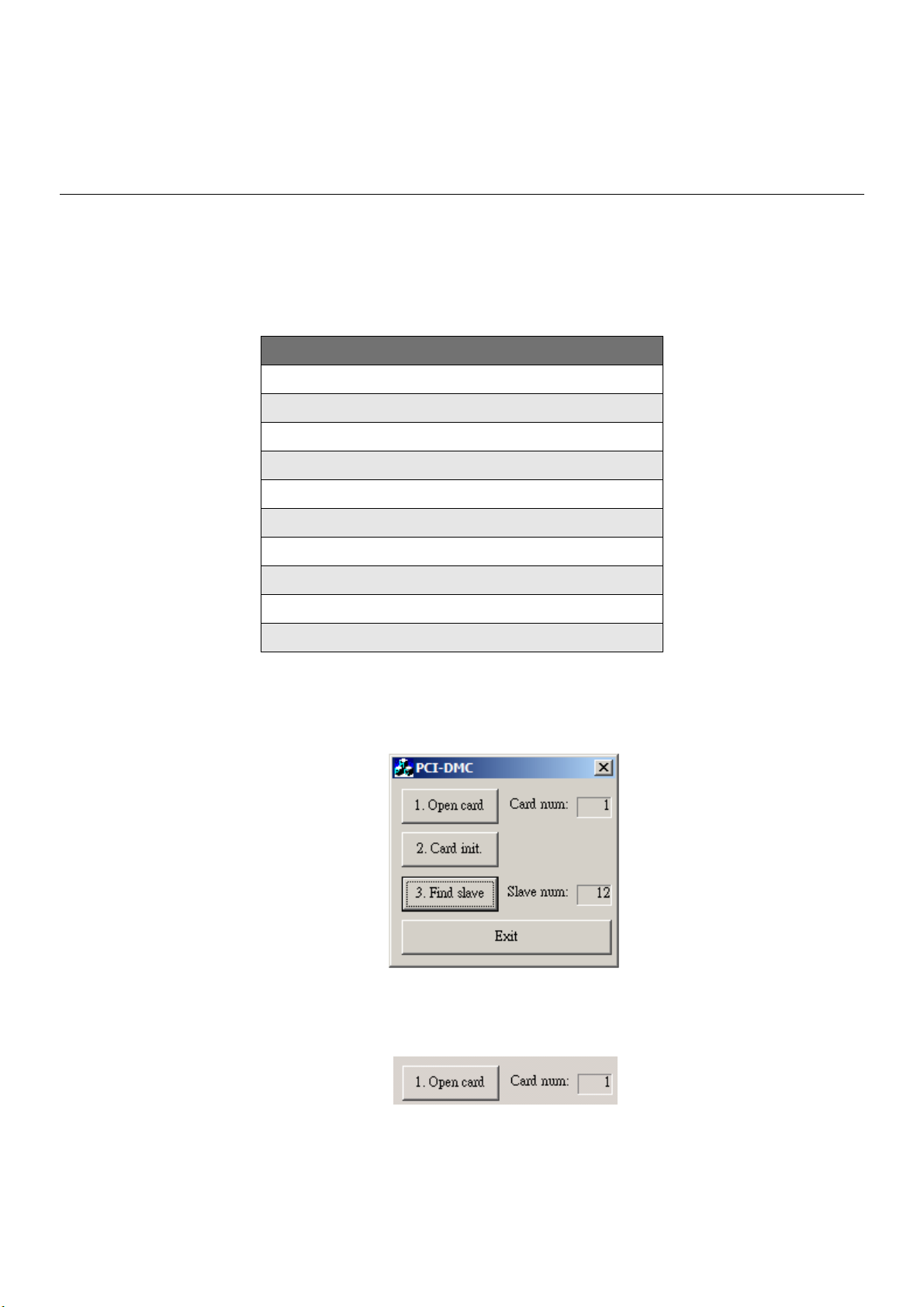
3.1.2 Sample Application
Program Appearance
Figure 3.1
1) Open card
Figure 3.2
Revised March, 2012 3-1
Page 24

Chapter 3 Operating Principles | PCI-DMC-A01 / PCI-DMC-B01
Click on the “Open card” button to execute the following procedure:
/* gDMCExistCards variable is set as the number of PCI-DMC-A01 on the PC*/
rt = _DMC_01_open(&gDMCExistCards);
2) Card initialization
Figure 3.3
Click on the “Card init” button to execute the following procedure:
for(i=0; i<gDMCExistCards; i++)
{
/* Get the card number of the i-th card on the PC. Card number is the value set by
the DIP Switch*/
rt = _DMC_01_get_CardNo_seq(i, &CardNo);
gpDMCCardNoList[i] = CardNo;
/*Check to see if the card has been initialized. If the value is 0, then the card has not
been initialized .*/
rt = _DMC_01_check_card_running(gpDMCCardNoList[i], &running);
if(running == 0) {
rt = _DMC_01_pci_initial(gpDMCCardNoList[i]); // Initialize card
if(rt != 0) AfxMessageBox(“Can't boot PCI_DMC_01 Master Card!”);
}
rt = _DMC_01_initial_bus(gpDMCCardNoList[i]); // Initialization communications
protocol
gbpDSPBoot[gpDMCCardNoList[i]] = true;
}
3) Establish communications
Figure 3.4
Click on the “Find slave” button to execute the following procedure:
rt = _DMC_01_start_ring(gDMCCardNo, 0); // Begin communications
rt = _DMC_01_get_device_table(gDMCCardNo, &gpDeviceInfo[gDMCCardNo]);
rt = _DMC_01_get_node_table(gDMCCardNo, &gpSlaveTable[0][gDMCCardNo]);
Once the above procedure has been executed, the detected Slave device is
displayed in the “Slave num” field.
3-2 Revised March, 2012
Page 25

Chapter 3 Operating Principles | PCI-DMC-A01 / PCI-DMC-B01
NOTE
_DMC_01_get_device_table Get the Slot ID using the PDO protocol
Example: gpDeviceInfo[gDMCCardNo] is a “WORD” type variable. If its value is 7,
the binary form is expressed as “0000 0000 0000 0111”, so Slave devices with Slot
IDs “1”, “2” and “3” exist.
_DMC_01_get_node_table Get Node ID using SDO protocol.
Example: gpSlaveTable[0][gDMCCardNo] is a “DWORD” type variable. If its value is
7, the binary form is expressed as “0000 0000 0000 0000 0000 0000 0000 0111”, so
Slave devices with Node ID “1”, “2”, and “3” exist.
※You can use the following algorithm to find the Node ID for SDO.
lMask = 0x1;
for(i=0; i<32; i++)
{
/* Condition is met when the i-th bit is 1. */
if((gpSlaveTable[0][gDMCCardNo]>>i) & lMask) {
/* The derived i-th value +1 is the Node ID and corresponds to servo parameter
“P3-00” */
gpNodeID[gNodeNum] = (unsigned short)(i+1);
gNodeNum++;
}
}
4) Exit procedure
Figure 3.5
Click on the “Exit” button to execute the following procedure:
for(i=0; i<gDMCExistCards; i++) {
rt = _DMC_01_reset_card(gpDMCCardNoList[i]); // Reset card
}
_DMC_01_close(); // Shut down PCI-DMC-A01
Revised March, 2012 3-3
Page 26
Chapter 3 Operating Principles | PCI-DMC-A01 / PCI-DMC-B01
3.2 Read/Write Driver Parameters
3.2.1 Function List
Table 3.2
Function Name
_DMC_01_set_pdo_mode
_DMC_01_read_servo_parameter
_DMC_01_write_servo_parameter
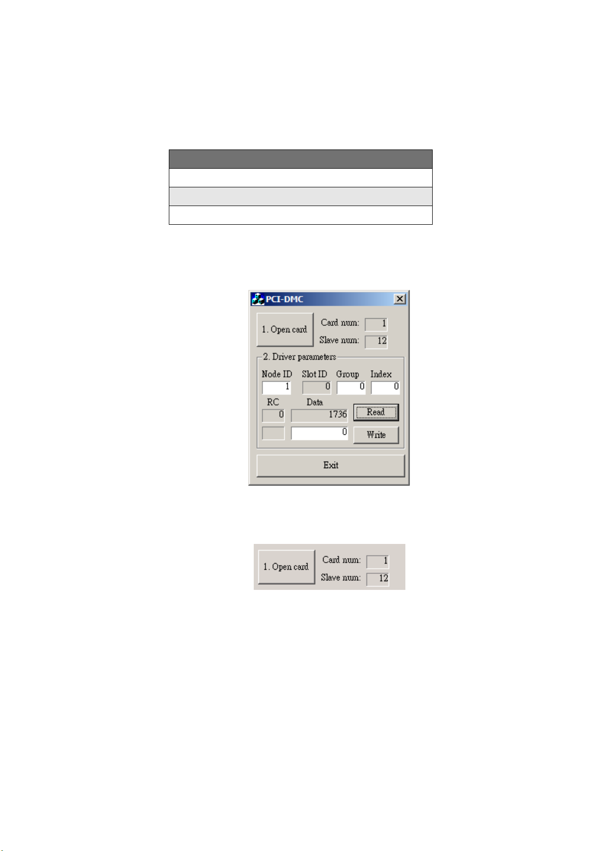
3.2.2 Sample Application
Program Appearance
Figure 3.6
1) Card Initialization and Mode Switching
Figure 3.7
Click on “Open card” to execute card initialization and set SDO mode.
For detailed instructions on card initialization, please refer to the functions described
in Section 3.1 between “Open card” and “Establish communications”.
Setting the SDO mode will use the following API function:
/* Set Slave communications to SDO mode */
rt = _DMC_01_set_pdo_mode(gDMCCardNo, gpNodeID[i], SlotID, 0);
3-4 Revised March, 2012
Page 27
Chapter 3 Operating Principles | PCI-DMC-A01 / PCI-DMC-B01
The last argument [Enable] is used to set whether PDO mode is used for Slave
communications or not. Please refer to the section on this function for a more
detailed description of this argument.
In the above example, the value of the argument is 0. This means PDO mode is
disabled during Slave communication.
If you set PDO mode to disabled, then Slave communications will use the SDO
protocol. If you need to use the SDO protocol to control the slave, you must set the
value of this argument to zero.
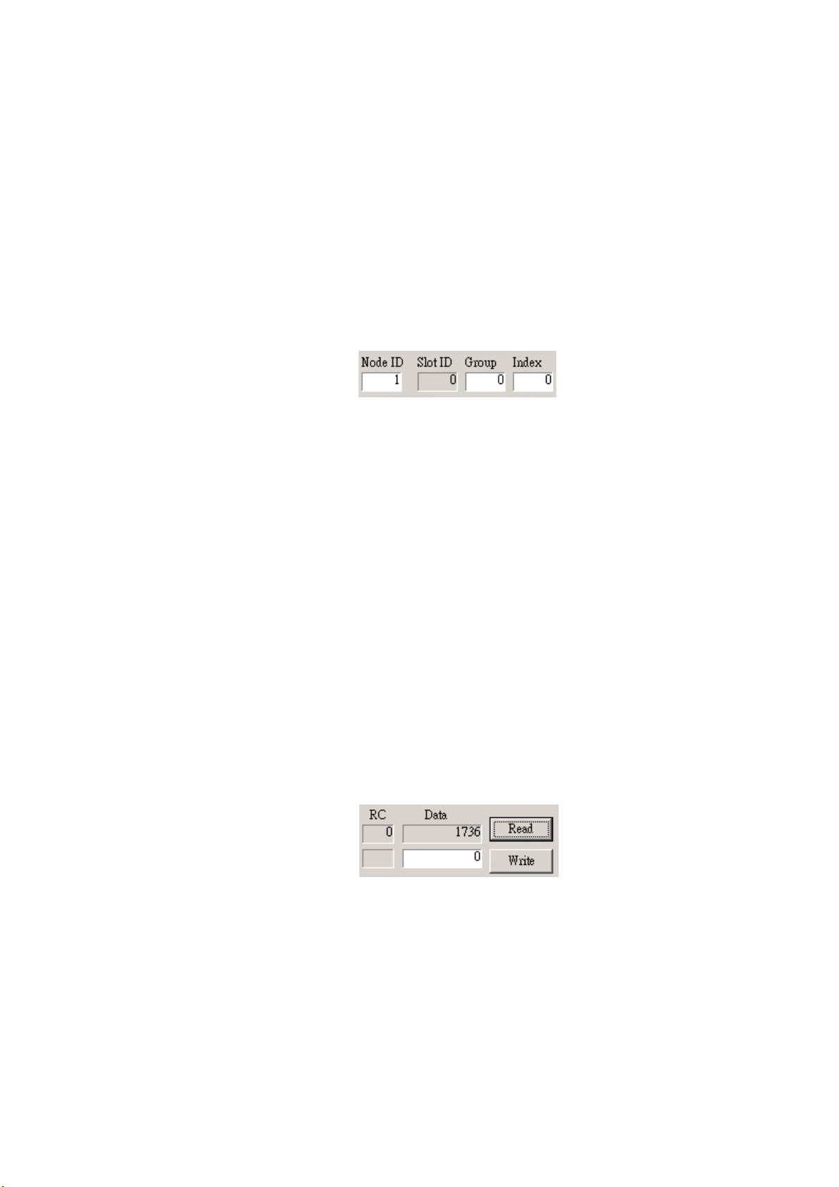
2) Input the servo to change (Including Node ID, Group No. and Index value)
Figure 3.8
For example, you can enter the values shown below in Fig. 3.8.
1st field - “Node ID”: If the value is 1, then it will operate the servo with Node ID 1.
2nd field - “Slot ID”: This field cannot be changed. It shows the current Slave
device (Servo's Slot ID is 0).
3rd Field - “Group”: Refers to the group number. of the device (usually a
servo). For a more detailed description of group number,
please refer to the “ASDA-A2 User Manual”. If Group is set to
0 as shown in Fig. 3.8, this means this will set the servo
parameter for “P0-xx” (the value of xx is explained below under
Index).
4th field - “Index”: As noted above, this value depends on the value for Group.
In Fig. 3.8, index has a value of 0 so in this case, read/write will
be carried on the “P0-00” parameter of Servo with Node ID of 1.
3) Read servo parameter
Figure 3.9
Click on the “Read” button to execute the following procedure:
rt = _DMC_01_read_servo_parameter(gDMCCardNo, NodeID, SlotID, group, idx,
&data);
// A data value will be returned. The value will be current value set for this servo
parameter.
// The value of rt will be displayed in the “RC” field while the value of data will be
displayed in the “Data” field.
Revised March, 2012 3-5
Page 28

Chapter 3 Operating Principles | PCI-DMC-A01 / PCI-DMC-B01
4) Write servo parameter
Figure 3.10
As shown in Fig. 3.10, if you wish to write a parameter value to servo then you must
input the desired value in the edit box and then click on the “Write” button to execute
the following procedure:
rt = _DMC_01_write_servo_parameter(gDMCCardNo, NodeID, SlotID, group, idx,
data);
//The value will be written to the servo group parameter you set. Please refer to the
previous section for a detailed description.
5) Exit procedure
Click on the “Exit” button to quit and exit the procedure.
“_DMC_01_reset_card” and “_DMC_01_close” must be executed to exit this
function. Please refer to Section 3.12 “Exit procedure” for the function operations.
3-6 Revised March, 2012
Page 29
3.3 CANopen Protocol
3.3.1 Function List
_DMC_01_set_pdo_mode
_DMC_01_send_message
_DMC_01_read_message
_DMC_01_get_message
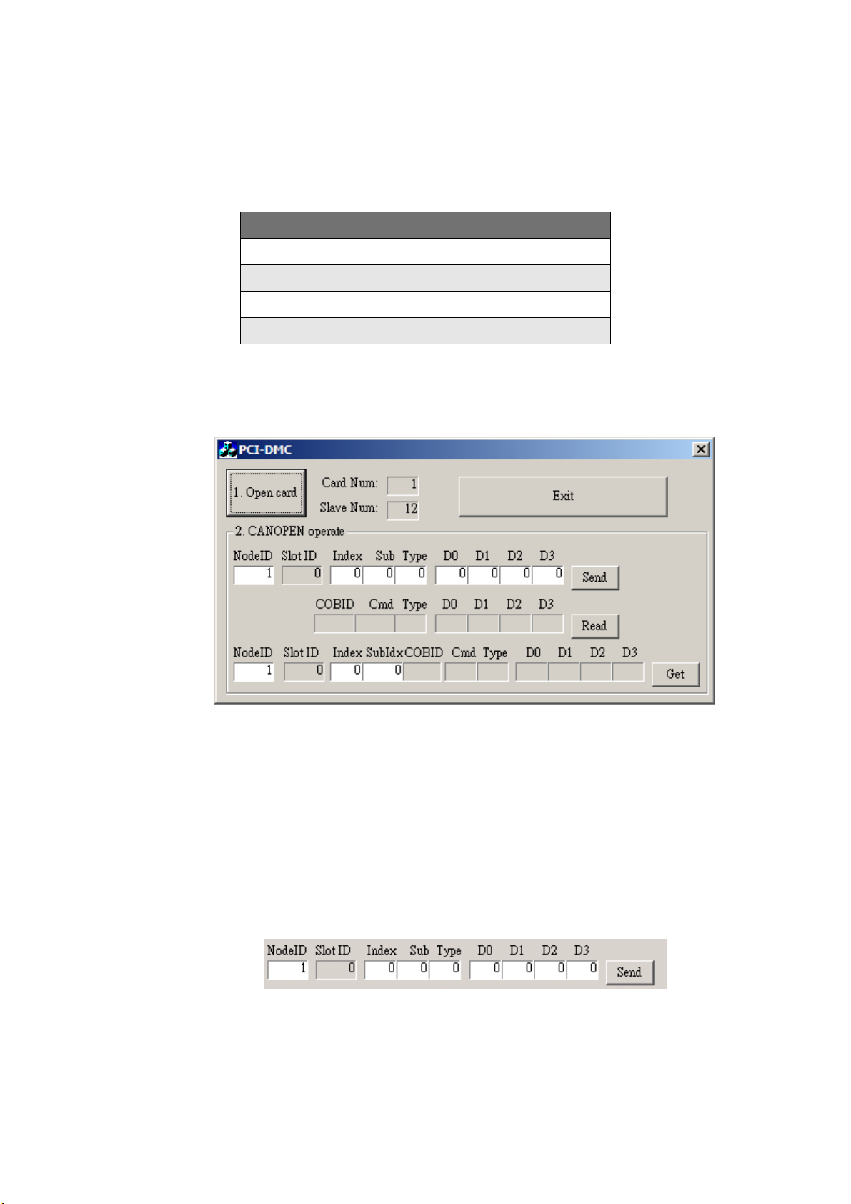
3.3.2 Sample Application
Program Appearance
Chapter 3 Operating Principles | PCI-DMC-A01 / PCI-DMC-B01
Table 3.3
Function Name
Figure 3.11
1) Initialize card and set Slave communications to SDO mode.
Click on the “Open card” button shown in Fig. 3.11 to initialize card and set SDO
mode.
A description of this button is provided in Section 3.2.2 “Card Initialization and Mode
Switching”.
2) Send SDO protocol command
Figure 3.12
Revised March, 2012 3-7
Page 30

Chapter 3 Operating Principles | PCI-DMC-A01 / PCI-DMC-B01
You input the value of the “NodeID”. The value will reflect the Slave ID you wish to
set up.
Please refer to th CANopen manual (DS 402) for setting the “Index”, “Sub” and
“Type” values.
The values “D0” to “D3” are used to input the SDO command data you wish to set
(Valid data: Byte).
Once you enter the above data, click on the “Send” button to execute the following
API function:
rt = _DMC_01_send_message(gDMCCardNo, NodeID, SlotID, Index, SubIdx,
DataType, Value0, Value1, Value2, Value3);
3) Command for reading SDO protocol
Figure 3.13
Click on the “Read” button to execute the following procedure:
/* Get the returned data for the last SDO command you sent*/
rt = _DMC_01_read_message(gDMCCardNo, &Cmd, & COBID, &DataType,
&Value0, &Value1, &Value2, &Value3);
You can create some variables to store the data returned by SDO commands. For
detailed description of the returned data, please see Section 8.8.
4) Command for getting SDO protocol
Figure 3.14
You must enter the corresponding Node ID, Object Dictionary (OD) index and
sub-index to get the information you want to know from the CANopen interface
protocol. Once you enter the data, click on the “Get” button to execute:
rt = _DMC_01_get_message(gDMCCardNo, NodeID, SlotID, Index, SubIndex,
&COBID, &Cmd , &DataType, &Value0, &Value1, &Value2, &Value3);
You can create some variables to store the data returned by SDO commands. For
detailed description of the returned data, please see Section 8.9.
5) Exit procedure
Click on the “Exit” button to quit and exit the procedure.
3-8 Revised March, 2012
Page 31

3.4 Homing Motion Control
3.4.1 Overview
Most application programs use an incremental encoder to retrieve position feedback. A
homing operation is essential to performing accurate motion control. After the power is
switched on, the status of the machine bench's position can be in one of three
states. First, position is stopped at the homing position awaiting the next command;
second, position is stopped at the ORG sensor; third, position is stopped somewhere
between ORG and Limit Switch (PEL and MEL). Please refer to the block diagram
in Fig. 3.15 below.
Chapter 3 Operating Principles | PCI-DMC-A01 / PCI-DMC-B01
1 2 13
M
PEL ORG MEL
Figure 3.15
PCI-DMC-A01 provides different functions for each of the above conditions. For homing
mode in a normal position, PCI-DMC-A01 offers up to 35 different reset to home
functions (including the reserved part). The user can simply use software settings to
have the hardware perform the user-selected homing operation. Once the homing
motion is complete, the corresponding command and feedback position will be cleared
to 0. The target position will however not be cleared to 0. The following graph shows the
conditions for executing homing:
Figure 3.16
Revised March, 2012 3-9
Page 32

Chapter 3 Operating Principles | PCI-DMC-A01 / PCI-DMC-B01
3.4.2 Function List
Table 3.4
Function Name
_DMC_01_set_home_config
_DMC_01_set_home_move
_DMC_01_escape_home_move
3.4.3 Sample Application
Program Appearance
Figure 3.17
1) Open card and initialization
Click on the “Initial” button to open and initialize the card.
For a detailed description of card initialization, please refer to “Open card” and “Card
initialization” in Section 3.1.2.
3-10 Revised March, 2012
Page 33

Chapter 3 Operating Principles | PCI-DMC-A01 / PCI-DMC-B01
2) Enter the values of the arguments for motion control
Figure 3.18
NodeID item: API function's argument variable “NodeID”.
Timer Checkbox: Check to display the motion status. Uncheck to disable display.
Vel. item: Number of pulses per second. API function's argument variable
“MaxVel”.
Acc. item: Time required to reach maximum velocity. API function's argument
variable “acc”.
3) Set homing parameter (Homing mode and offset)
Figure 3.19
Mode item: Homing modes 1 to 35. API function's argument variable
“home_mode”.
Offset item: Homing offsetAPI function's argument variable “home_offset”.
4) Set Servo Motor Power ON/OFF(servo on/servo off)
Figure 3.20
Click on the “SVON” button to execute the following procedure:
rt = _DMC_01_ipo_set_svon(gDMCCardNo, NodeID, SlotID , ON_OFF);
// ON_OFF: 0 – Servo Power OFF; 1 – Servo Power ON
Revised March, 2012 3-11
Page 34

Chapter 3 Operating Principles | PCI-DMC-A01 / PCI-DMC-B01
5) Homing operation
See Fig. 3.20. Click on “Move” to begin executing the following procedure;
/* Set homing mode: 1~35, offset and velocity parameters */
rt = _DMC_01_set_home_config(gDMCCardNo, NodeID, SlotID, home_mode,
home_offset, StrVel, MaxVel, acc);
/* Start homing motion */
rt = _DMC_01_set_home_move(gDMCCardNo, NodeID, SlotID);
6) Stop homing motion
If you wish to stop the homing motion operation, you must hit the “STOP” button to
execute the following procedure:
/* Interrupt homing motion */
rt = _DMC_01_escape_home_move(gDMCCardNo, NodeID, SlotID);
7) Exit procedure
Click on the “Exit” button to quit and exit the procedure.
“_DMC_01_reset_card” and “_DMC_01_close” must be executed to exit this
function. Please refer to Section 3.12 “Exit procedure” for the function operations.
3-12 Revised March, 2012
Page 35

3.5 Torque Motion Control
3.5.1 Function List
_DMC_01_set_torque_mode
_DMC_01_set_torque
_DMC_01_set_torque_stop
_DMC_01_get_torque
3.5.2 Sample Application
Program Appearance
Chapter 3 Operating Principles | PCI-DMC-A01 / PCI-DMC-B01
Table 3.5
Function Name
Figure 3.21
1) Card initialization
Click on the “Initial” button to open and initialize the card.
For a detailed description of card initialization, please refer to “Open card” and “Card
initialization” in Section 3.1.2.
2) Set Servo Node ID and enable motion status display
Figure 3.22
Revised March, 2012 3-13
Page 36

Chapter 3 Operating Principles | PCI-DMC-A01 / PCI-DMC-B01
Input Node ID and check the “Timer” checkbox to enable motion status display
NodeID item: API function argument variable “NodeID”.
Timer Checkbox: Check to display the motion status. Uncheck to disable display.
3) Enter values for slope and ratio
Figure 3.23
Slope item: Time required to go from 0 to 100% rate torque. (Unit: ms)
Ratio item: Thousandths of rated torque. For example, a value of 100 represents
10% of rated torque.
4) Set Servo Motor Power ON/OFF(servo on/servo off)
Figure 3.24
Click on the “SVON” button to execute the following procedure:
rt = _DMC_01_ipo_set_svon (gDMCCardNo, NodeID, SlotID , ON_OFF);
// ON_OFF: 0 – Servo Power OFF; 1 – Servo Power ON
5) Torque Motion Control
Click on the “” or “” button to execute the following procedure:
/* Set torque parameter (slope value) */
rt = _DMC_01_set_torque_mode(gDMCCardNo, NodeID, SlotID, slope);
/* Start torque motion */
rt = _DMC_01_set_torque(gDMCCardNo, NodeID, SlotID, ratio);
// If ratio is greater than 0, the motor rotates clockwise. If ratio is less than 0, the
motor rotates counterclockwise.
Press the “STOP” button to execute torque stop or not
/* Whether the motor's torque motion has stopped or not depends on the Stop value.
If Stop value is 1 then torque motion has stopped. */
rt = _DMC_01_set_torque_stop(gDMCCardNo, NodeID, SlotID, stop);
6) Display current torque value
rt = _DMC_01_get_torque(gDMCCardNo, NodeID, SlotID, &torque);
// torque variable will return current torque value
3-14 Revised March, 2012
Page 37

Chapter 3 Operating Principles | PCI-DMC-A01 / PCI-DMC-B01
7) Exit procedure
Click on the “Exit” button to quit and exit the procedure.
“_DMC_01_reset_card” and “_DMC_01_close” must be executed to exit this
function. Please refer to Section 3.12 “Exit procedure” for the function operations.
Revised March, 2012 3-15
Page 38

Chapter 3 Operating Principles | PCI-DMC-A01 / PCI-DMC-B01
3.6 Velocity Motion Control (1)
3.6.1 Function List
Table 3.6
Function Name
_DMC_01_set_velocity_mode
_DMC_01_set_velocity
_DMC_01_set_velocity_stop
_DMC_01_get_rpm
3.6.2 Sample Application
Program Appearance
Figure 3.25
1) Card initialization
Click on the “Initial” button to open and initialize the card.
For a detailed description of card initialization, please refer to “Open card” and “Card
initialization” in Section 3.1.2.
2) Set Servo Node ID and enable motion status display
Figure 3.26
3-16 Revised March, 2012
Page 39

Chapter 3 Operating Principles | PCI-DMC-A01 / PCI-DMC-B01
Input Node ID and check the “Timer” checkbox to enable motion status display
NodeID item: API function's argument variable “NodeID”.
Timer Checkbox: Check to display the motion status. Uncheck to disable display.
3) Enter the values for acceleration/deceleration time and rotations per minute (RPM)
Figure 3.27
Tacc item API function's argument variable “Tacc”.
Tdec item: API function's argument variable “Tdec”.
RPM item: API function's argument variable “rpm”.
※Actual RPM is 10% of rpm variable.
4) Set Servo Motor Power ON/OFF(servo on/servo off)
Figure 3.28
Click on the “SVON” button to execute the following procedure:
rt = _DMC_01_ipo_set_svon(gDMCCardNo, NodeID, SlotID , ON_OFF);
// ON_OFF: 0 – Servo Power OFF; 1 – Servo Power ON
5) Velocity Motion Control
Click on the “” or “” button to execute the following procedure:
/* Set velocity mode parameter (value for acceleration and deceleration time)) */
rt = _DMC_01_set_velocity_mode(gDMCCardNo, NodeID, SlotID, Tacc, Tdec);
/* Start velocity mode motion */
rt = _DMC_01_set_velocity(gDMCCardNo, NodeID, SlotID, rpm);
// If value of RPM is greater than 0 then drive motor rotates clockwise. if value is less
than 0 then rotates counterclockwise.
Press the “STOP” button to execute velocity stop or not.
/* Set whether to stop velocity motion control. If stop value is 1 then velocity motion
stops. */
rt = _DMC_01_set_velocity_stop(gDMCCardNo, NodeID, SlotID, stop);
Revised March, 2012 3-17
Page 40

Chapter 3 Operating Principles | PCI-DMC-A01 / PCI-DMC-B01
6) Display current RPM value
rt = _DMC_01_get_rpm (gDMCCardNo, NodeID, SlotID, & rpm);
// Value returned by RPM variableActual motion RPM is 10% of RPM variable value
7) Exit procedure
Click on the “Exit” button to quit and exit the procedure.
“_DMC_01_reset_card” and “_DMC_01_close” must be executed to exit this
function. Please refer to Section 3.12 “Exit procedure” for the function operations.
3-18 Revised March, 2012
Page 41

3.7 Velocity Motion Control (2)
3.7.1 Function List
_DMC_01_tv_move
_DMC_01_sv_move
_DMC_01_emg_stop
3.7.2 Sample Application
Program Appearance
Chapter 3 Operating Principles | PCI-DMC-A01 / PCI-DMC-B01
Table 3.7
Function Name
Figure 3.29
1) Card initialization
Click on the “Initial” button to open and initialize the card.
For a detailed description of card initialization, please refer to “Open card” and “Card
initialization” in Section 3.1.2.
2) Set Servo Node ID and enable motion status display
Figure 3.30
Input Node ID and check the “Timer” checkbox to enable motion status display
NodeID item: API function's argument variable “NodeID”.
Timer Checkbox: Check to display the motion status. Uncheck to disable display.
Revised March, 2012 3-19
Page 42

Chapter 3 Operating Principles | PCI-DMC-A01 / PCI-DMC-B01
3) Enter the values of the arguments for motion control
Figure 3.31
StrVel item: Starting velocity. API function's argument variable “StrVel”.
MaxVel item: Maximum velocity. API function's argument variable “MaxVel”.
Acc. item: Time required to reach maximum velocity. API function's argument
variable “acc”.
S-Curve checkbox: You must check this box if you wish to use the S-curve velocity
curve.
4) Set Servo Motor Power ON/OFF(servo on/servo off)
Click on the “SVON” button to execute the following procedure:
rt = _DMC_01_ipo_set_svon(gDMCCardNo, NodeID, SlotID , ON_OFF);
// ON_OFF: 0 – Servo Power OFF; 1 – Servo Power ON
5) Start velocity motion control
Click on the “” or ““ button to execute the following procedure:
/* S-curve velocity curve */
rt = _DMC_01_sv_move(gDMCCardNo, NodeID, SlotID, StrVel, MaxVel, acc, 0);
/* T-curve velocity curve */
rt = _DMC_01_tv_move(gDMCCardNo, NodeID, SlotID, StrVel, MaxVel, acc, 0);
6) Stop motion
Hit the “STOP” button to execute an emergency stop:
rt = _DMC_01_emg_stop (gDMCCardNo, NodeID, SlotID);
In this example, emergency stop is used to stop motion. This method quickly stops
motion by setting deceleration time to 0. For more information about the Stop Motion
function, refer to the later section on “Stop Motion Control API”.
7) Exit procedure
Click on the “Exit” button to quit and exit the procedure.
“_DMC_01_reset_card” and “_DMC_01_close” must be executed to exit this
function. Please refer to Section 3.12 “Exit procedure” for the function operations.
3-20 Revised March, 2012
Page 43

Chapter 3 Operating Principles | PCI-DMC-A01 / PCI-DMC-B01
3.8 Point to Point Motion Control
3.8.1 Overview
Point to point motion control can be used with single and multi-axes.
For single- or multi-axes point to point motion control, PCI-DMC-A01 absolute or
relative coordinate motion modes with a S-Curve or T-curve velocity cross-section.
Fig. 3.32 for example shows motion displacement from P0 to P1 along a single axis.
You can choose to use T-curve or S-curve motion modes based on relative or absolute
coordinates for motion displacement.
3.8.2 Function List
_DMC_01_ipo_set_svon
_DMC_01_start_tr_move
_DMC_01_start_sr_move
_DMC_01_start_ta_move
_DMC_01_start_sa_move
P0 P1
Figure 3.32
Table 3.8
Function Name
_DMC_01_sd_stop
_DMC_01_set_command
_DMC_01_set_position
_DMC_01_get_command
_DMC_01_get_position
_DMC_01_get_current_speed
_DMC_01_motion_status
DMC_01_motion_done
Revised March, 2012 3-21
Page 44

Chapter 3 Operating Principles | PCI-DMC-A01 / PCI-DMC-B01
3.8.3 Sample Application
Program Appearance
Figure 3.33
1) Card initialization
Click on the “Initial” button to open and initialize the card.
For a detailed description of card initialization, please refer to “Open card” and “Card
initialization” in Section 3.1.2.
2) Set Servo Node ID and enable motion status display
Figure 3.34
Input Node ID and check the “Timer” checkbox to enable motion status display
NodeID item: API function's argument variable “NodeID”.
Timer Checkbox: Check to display the motion status. Uncheck to disable display.
3-22 Revised March, 2012
Page 45

Chapter 3 Operating Principles | PCI-DMC-A01 / PCI-DMC-B01
3) Enter the values of the arguments for motion control
Figure 3.35
StrVel item: Starting velocity. API function's argument variable “StrVel”.
MaxVel item: Maximum velocity. API function's argument variable “MaxVel”.
Acc. item: Time required to reach maximum velocity. API function's argument
variable “acc”.
Dec item: Time required to go from maximum velocity to 0. API function's argument
variable “dec”.
4) Select motion mode and set motion distance.
Figure 3.36
Abs. Checkbox: You must check this if you want motion displacement to use
absolute coordinates.
S-Curve checkbox: You must check this box if you wish to use the S-curve velocity
curve.
Dist. item: Motion distance. API function's argument variable “Distance”.
5) Set Servo Motor Power ON/OFF(servo on/servo off)
Figure 3.37
Click on the “SVON” button to execute the following procedure:
rt = _DMC_01_ipo_set_svon(gDMCCardNo, NodeID, SlotID , ON_OFF);
// ON_OFF: 0 – Servo Power OFF; 1 – Servo Power ON
Revised March, 2012 3-23
Page 46

Chapter 3 Operating Principles | PCI-DMC-A01 / PCI-DMC-B01
6) Start point to point motion control
Click on the “” or ““ button to execute the following procedure:
rt = _DMC_01_start_sa_move(gDMCCardNo, NodeID, SlotID, Distance, StrVel,
MaxVel, acc, dec);
// Motion displacement using absolute coordinates with S-curve velocity
cross-section
rt = _DMC_01_start_ta_move(gDMCCardNo, NodeID, SlotID, Distance, StrVel,
MaxVel, acc, dec);
// Motion displacement using absolute coordinates with T-curve velocity
cross-section
rt = _DMC_01_start_sr_move(gDMCCardNo, NodeID, SlotID, Distance, StrVel,
MaxVel, acc, dec);
// Motion displacement using relative coordinates with S-curve velocity cross-section
rt = _DMC_01_start_tr_move(gDMCCardNo, NodeID, SlotID, Distance, StrVel,
MaxVel, acc, dec);
// Motion displacement using relative coordinates with T-curve velocity cross-section
7) Reset motion displacement counter (Command and Feedback)
Figure 3.38
Click on the “RESET” button to execute reset command:
/* If you wish to reset the command and feedback counters, you must first set drive
motor to "servo off" */
if(gbIsSVON)
rt = _DMC_01_ipo_set_svon(gDMCCardNo, NodeID, SlotID , 0);
/* The motion counters can only be cleared when the motor is confirmed to be
"servo off" */
rt = _DMC_01_set_command(gDMCCardNo, NodeID, SlotID, 0); // Clear command
rt = _DMC_01_set_position(gDMCCardNo, NodeID, SlotID, 0); // Clear feedback
/* Once the command and feedback counters are cleared, set drive motors to "servo
on" again */
if(gbIsSVON)
rt = _DMC_01_ipo_set_svon(gDMCCardNo, NodeID, SlotID , 1);
3-24 Revised March, 2012
Page 47

Chapter 3 Operating Principles | PCI-DMC-A01 / PCI-DMC-B01
Motion counter value:
rt = _DMC_01_get_command(gDMCCardNo, NodeID, SlotID, &cmd);
// Get value of command counter
rt = _DMC_01_get_position(gDMCCardNo, NodeID, SlotID, &pos);
// Get value of feedback counter
Motion status:
rt = _DMC_01_get_current_speed(gDMCCardNo, NodeID, SlotID, &speed);
// Get velocity of current motion
rt = _DMC_01_motion_status(gDMCCardNo, NodeID, SlotID, &MC_status);
// Get current status
rt = _DMC_01_motion_done(gDMCCardNo, NodeID, SlotID, &MC_done);
// Get current motor status
8) Stop motion
Figure 3.39
Hit the “STOP” button to execute an emergency stop:
rt = _DMC_01_emg_stop (gDMCCardNo, NodeID, SlotID);
In this example, emergency stop is used to stop motion. This method quickly stops
motion by setting deceleration time to 0. For more information about the Stop Motion
function, refer to the later section on “Stop Motion Control API”.
9) Exit procedure
Click on the “Exit” button to quit and exit the procedure.
“_DMC_01_reset_card” and “_DMC_01_close” must be executed to exit this
function. Please refer to Section 3.12 “Exit procedure” for the function operations.
Revised March, 2012 3-25
Page 48

Chapter 3 Operating Principles | PCI-DMC-A01 / PCI-DMC-B01
3.9 Linear Interpolation Motion Control
3.9.1 Overview
If you wish to use CANopen PDO protocol for motion control you must operate in the
CANopen IP mode.
PCI-DMC-A01 supports 2~3 axis linear interpolation in absolute or relative coordinate
motion modes under the S-curve or T-curve velocity cross-section.
2-axis linear interpolation is as shown in Fig. 3.30.
This is a straight line that starts and P0 and ends at P1 in 2 dimensions.
Velocity is the vector speeds (dX:dY) along the X and Y axes as shown in Fig. 3.37:
Y
1(X1,Y1)
P
3.9.2 Function List
_DMC_01_start_tr_move_xy
_DMC_01_start_sr_move_xy
_DMC_01_start_ta_move_xy
_DMC_01_start_sa_move_xy
_DMC_01_start_tr_move_xyz
0(X0,Y0)
P
dX
Figure 3.40
Table 3.9
Function Name
dY
X
_DMC_01_start_sr_move_xyz
_DMC_01_start_ta_move_xyz
_DMC_01_start_sa_move_xyz
_DMC_01_sd_stop
3-26 Revised March, 2012
Page 49

Chapter 3 Operating Principles | PCI-DMC-A01 / PCI-DMC-B01
3.9.3 Sample Application
Program Appearance
Figure 3.41
1) Card initialization
Click on the “Initial” button to start card initialization.
For a detailed description of card initialization, please refer to Section 3.1.2 - 1)
Open card.
2) Get Slot ID and enable motion status display
Figure 3.42
Check the “Timer” checkbox to enable motion status display
Timer Checkbox: Check to display the motion status. Uncheck to disable display.
Revised March, 2012 3-27
Page 50

Chapter 3 Operating Principles | PCI-DMC-A01 / PCI-DMC-B01
3) Enter the values of the arguments for motion control
Figure 3.43
StrVel item: Starting velocity. API function's argument variable “StrVel”.
MaxVel item: Maximum velocity. API function's argument variable “MaxVel”.
Acc. item: Time required to reach maximum velocity. API function's argument
variable “acc”.
Dec item: Time required to go from maximum velocity to 0. API function's argument
variable “dec”.
4) Select motion mode and set motion distance.
Figure 3.44
Abs. Checkbox: You must check this if you want motion displacement to use
absolute coordinates.
S-Curve checkbox: You must check this box if you wish to use the S-curve velocity
curve.
Dist. item: Motion distance. API function's argument variable “Distance”.
5) Set Servo Motor Power ON/OFF(servo on/servo off)
Figure 3.45
Click on the “SVON” button to execute the following procedure:
rt = _DMC_01_ipo_set_svon(gDMCCardNo, NodeID, SlotID , ON_OFF);
// ON_OFF: 0 – Servo Power OFF; 1 – Servo Power ON
3-28 Revised March, 2012
Page 51

Chapter 3 Operating Principles | PCI-DMC-A01 / PCI-DMC-B01
6) Start motion control with linear interpolation in 2 or 3 axes
Click on the “” or ““ button to execute the following procedure:
2-axis linear interpolation:
rt = _DMC_01_start_sa_move_xy(gDMCCardNo, gLine2, gSlot2, Distance,
Distance, StrVel, MaxVel, acc, dec);
//// Linear interpolation motion using absolute coordinates with S-curve velocity
cross-section
rt = _DMC_01_start_ta_move_xy(gDMCCardNo, gLine2, gSlot2, Distance,
Distance, StrVel, MaxVel, acc, dec); //// Linear interpolation motion using absolute
coordinates with T-curve velocity cross-section
rt = _DMC_01_start_sr_move_xy(gDMCCardNo, gLine2, gSlot2, Distance,
Distance, StrVel, MaxVel, acc, dec);
//// Linear interpolation motion using relative coordinates with S-curve velocity
cross-section
rt = _DMC_01_start_tr_move_xy(gDMCCardNo, gLine2, gSlot2, Distance, Distance,
StrVel, MaxVel, acc, dec); //// Linear interpolation motion using relative coordinates
with T-curve velocity cross-section
3-axis linear interpolation:
rt = _DMC_01_start_sa_move_xyz(gDMCCardNo, gLine3, gSlot3, Distance,
Distance, Distance, StrVel, MaxVel, acc, dec);
//// Linear interpolation motion using absolute coordinates with S-curve velocity
cross-section
rt = _DMC_01_start_ta_move_xyz(gDMCCardNo, gLine3, gSlot3, Distance,
Distance, Distance, StrVel, MaxVel, acc, dec);
//// Linear interpolation motion using absolute coordinates with T-curve velocity
cross-section
rt = _DMC_01_start_sr_move_xyz(gDMCCardNo, gLine3, gSlot3, Distance,
Distance, Distance, StrVel, MaxVel, acc, dec);
//// Linear interpolation motion using relative coordinates with S-curve velocity
cross-section
rt = _DMC_01_start_tr_move_xyz(gDMCCardNo, gLine3, gSlot3, Distance,
Distance, Distance, StrVel, MaxVel, acc, dec);
//// Linear interpolation motion using relative coordinates with T-curve velocity
cross-section
Revised March, 2012 3-29
Page 52

Chapter 3 Operating Principles | PCI-DMC-A01 / PCI-DMC-B01
7) Stop motion
Figure 3.46
Hit the “STOP” button to execute an emergency stop:
rt = _DMC_01_emg_stop (gDMCCardNo, NodeID, SlotID);
In this example, emergency stop is used to stop motion. This method quickly stops
motion by setting deceleration time to 0. For more information about the Stop Motion
function, refer to the later section on “Stop Motion Control API”.
8) Exit procedure
Click on the “Exit” button to quit and exit the procedure.
“_DMC_01_reset_card” and “_DMC_01_close” must be executed to exit this
function. Please refer to Section 3.12 “Exit procedure” for the function operations.
3-30 Revised March, 2012
Page 53

Chapter 3 Operating Principles | PCI-DMC-A01 / PCI-DMC-B01
3.10 Arc Interpolation Motion Control
3.10.1 Overview
PCI-DMC-A01 supports 2-axis arc interpolation in absolute or relative coordinate
motion modes under the S-curve or T-curve velocity cross-section. Fig. 3.44 illustrates
arc interpolation on any 2 axes.
The start point is P0 (X0, Y0) and end point is P1(X1, Y1). The path from P0 to P1
forms an arc. The maximum velocity is the tangential velocity.
P0
3.10.2 Function List
Cent
P1
Figure 3.47
Table 3.10
Function Name
_DMC_01_start_tr_arc_xy
_DMC_01_start_sr_arc_xy
_DMC_01_start_ta_arc_xy
_DMC_01_start_sa_arc_xy
_DMC_01_start_tr_arc2_xy
_DMC_01_start_sr_arc2_xy
_DMC_01_start_ta_arc2_xy
_DMC_01_start_sa_arc2_xy
_DMC_01_start_tr_arc3_xy
_DMC_01_start_sr_arc3_xy
_DMC_01_start_ta_arc3_xy
_DMC_01_start_sa_arc3_xy
Revised March, 2012 3-31
Page 54

Chapter 3 Operating Principles | PCI-DMC-A01 / PCI-DMC-B01
3.10.3 Sample Application
Program Appearance
Figure 3.48
1) Card initialization
Click on the “Initial” button to open and initialize the card.
For a detailed description of card initialization, please refer to “Open card” and “Card
initialization” in Section 3.1.2.
2) Get Slot ID and enable motion status display
Figure 3.49
Check the “Timer” checkbox to enable motion status display
Timer Checkbox: Check to display the motion status. Uncheck to disable display.
3) Enter the values of the arguments for motion control
Figure 3.50
3-32 Revised March, 2012
Page 55

Chapter 3 Operating Principles | PCI-DMC-A01 / PCI-DMC-B01
StrVel item: Starting velocity. API function's argument variable “StrVel”.
MaxVel item: Maximum velocity. API function's argument variable “MaxVel”.
Acc. item: Time required to reach maximum velocity. API function's argument
variable “acc”.
Dec item: Time required to go from maximum velocity to 0. API function's argument
variable “dec”.
Abs. Checkbox: You must check this if you want motion displacement to use
absolute coordinates.
S-Curve checkbox: You must check this box if you wish to use the S-curve velocity
curve.
4) Select the type of 2-axis arc interpolation and enter the corresponding values
➊
➌
Figure 3.51
➋
Arc 1: Interpolation method 1. Must provide the center coordinates (X, Y) and angle
(0o to 359o)
➊ Cen_X item: Center's x-coordinate. API function's argument variable
“arc1_cen_x”.
Cen_Y item: Center's y-coordinate. API function's argument variable
“arc1_cen_y”.
Angle item: Angle. API function's argument variable “arc1_angle”.
Arc 2: Interpolation method 2. Must enter the endpoint coordinates (X, Y) and angle
(0o to 359o)
➋ End_X item: Endpoint's x-coordinate. API function's argument variable
“arc2_end_x”.
End_Y item: Endpoint's Y-coordinate. API function's argument variable
“arc2_end_y”.
Angle item: Angle. API function's argument variable “arc2_angle”.
Arc 3: Interpolation method 3. Must provide the center coordinates (X, Y), endpoint
coordinates (X, Y) and direction.
Revised March, 2012 3-33
Page 56

Chapter 3 Operating Principles | PCI-DMC-A01 / PCI-DMC-B01
➌ Cen_X item: Center's x-coordinate. API function's argument variable
“arc3_cen_x”.
Cen_Y item: Center's y-coordinate. API function's argument variable
“arc3_cen_y”.
End_X item: Endpoint's x-coordinate. API function's argument variable
“arc3_end_x”.
End_Y item: Endpoint's Y-coordinate. API function's argument variable
“arc3_end_y”.
Dir item: Direction. API function's argument variable “arc3_dir”.
When this value is 0, the servo motor will rotate clockwise (CW).
When this value is 1, the servo motor will counterclockwise (CCW).
5) Set Servo Motor Power ON/OFF(servo on/servo off)
Figure 3.52
Click on the “SVON” button to execute the following procedure:
rt = _DMC_01_ipo_set_svon(gDMCCardNo, NodeID, SlotID , ON_OFF);
// ON_OFF: 0 – Servo Power OFF; 1 – Servo Power ON
6) Start 2-axis arc interpolation motion control
Click on the “” or ““ button to execute the following procedure:
2-axis arc interpolation using interpolation method 1 (Arc1):
rt = _DMC_01_start_sa_arc_xy(gDMCCardNo, gArcNode, gSlot2, arc1_cen_x,
arc1_cen_y, arc1_angle, StrVel, MaxVel, acc, dec);
// Arc interpolation motion using absolute coordinates under the S-curve velocity
cross-section
rt = _DMC_01_start_ta_arc_xy(gDMCCardNo, gArcNode, gSlot2, arc1_cen_x,
arc1_cen_y, arc1_angle, StrVel, MaxVel, acc, dec);
// Arc interpolation motion using absolute coordinates under the T-curve velocity
cross-section
rt = _DMC_01_start_sr_arc_xy(gDMCCardNo, gArcNode, gSlot2, arc1_cen_x,
arc1_cen_y, arc1_angle, StrVel, MaxVel, acc, dec);
// Arc interpolation motion using relative coordinates under the S-curve velocity
cross-section
rt = _DMC_01_start_tr_arc_xy(gDMCCardNo, gArcNode, gSlot2, arc1_cen_x,
arc1_cen_y, arc1_angle, StrVel, MaxVel, acc, dec);
// Arc interpolation motion using relative coordinates under the T-curve velocity
cross-section
3-34 Revised March, 2012
Page 57

Chapter 3 Operating Principles | PCI-DMC-A01 / PCI-DMC-B01
2-axis arc interpolation using interpolation method 2 (Arc2).
rt = _DMC_01_start_sa_arc2_xy(gDMCCardNo, gArcNode, gSlot2, arc2_end_x,
arc2_end_y, arc2_angle, StrVel, MaxVel, acc, dec);
// Arc interpolation motion using absolute coordinates under the S-curve velocity
cross-section
rt = _DMC_01_start_ta_arc2_xy(gDMCCardNo, gArcNode, gSlot2, arc2_end_x,
arc2_end_y, arc2_angle, StrVel, MaxVel, acc, dec);
// Arc interpolation motion using absolute coordinates under the T-curve velocity
cross-section
rt = _DMC_01_start_sr_arc2_xy(gDMCCardNo, gArcNode, gSlot2, arc2_end_x,
arc2_end_y, arc2_angle, StrVel, MaxVel, acc, dec);
// Arc interpolation motion using relative coordinates under the S-curve velocity
cross-section
rt = _DMC_01_start_tr_arc2_xy(gDMCCardNo, gArcNode, gSlot2, arc2_end_x,
arc2_end_y, arc2_angle, StrVel, MaxVel, acc, dec);
// Arc interpolation motion using relative coordinates under the T-curve velocity
cross-section
2-axis arc interpolation using interpolation method 3 (Arc3):
rt = _DMC_01_start_sa_arc3_xy(gDMCCardNo, gArcNode, gSlot2, arc3_cen_x,
arc3_cen_y, arc3_end_x, arc3_end_y, arc3_dir, StrVel, MaxVel, acc, dec);
// Arc interpolation motion using absolute coordinates under the S-curve velocity
cross-section
rt = _DMC_01_start_ta_arc3_xy(gDMCCardNo, gArcNode, gSlot2, arc3_cen_x,
arc3_cen_y, arc3_end_x, arc3_end_y, arc3_dir, StrVel, MaxVel, acc, dec);
// Arc interpolation motion using absolute coordinates under the T-curve velocity
cross-section
rt = _DMC_01_start_sr_arc3_xy(gDMCCardNo, gArcNode, gSlot2, arc3_cen_x,
arc3_cen_y, arc3_end_x, arc3_end_y, arc3_dir, StrVel, MaxVel, acc, dec);
// Arc interpolation motion using relative coordinates under the S-curve velocity
cross-section
rt = _DMC_01_start_tr_arc3_xy(gDMCCardNo, gArcNode, gSlot2, arc3_cen_x,
arc3_cen_y, arc3_end_x, arc3_end_y, arc3_dir, StrVel, MaxVel, acc, dec);
// Arc interpolation motion using relative coordinates under the T-curve velocity
cross-section
7) Stop motion
Figure 3.53
Revised March, 2012 3-35
Page 58

Chapter 3 Operating Principles | PCI-DMC-A01 / PCI-DMC-B01
Hit the “STOP” button to execute an emergency stop:
rt = _DMC_01_emg_stop (gDMCCardNo, NodeID, SlotID);
In this example, emergency stop is used to stop motion. This method quickly stops
motion by setting deceleration time to 0. For more information about the Stop Motion
function, refer to the later section on “Stop Motion Control API”.
8) Exit procedure
Click on the “Exit” button to quit and exit the procedure.
“_DMC_01_reset_card” and “_DMC_01_close” must be executed to exit this
function. Please refer to Section 3.12 “Exit procedure” for the function operations.
3-36 Revised March, 2012
Page 59

Chapter 3 Operating Principles | PCI-DMC-A01 / PCI-DMC-B01
3.11 Spiral Interpolation Motion Control -Helix
3.11.1 Function List
Table 3.11
Function Name
_DMC_01_start_tr_heli_xy
_DMC_01_start_sr_heli_xy
_DMC_01_start_ta_heli_xy
_DMC_01_start_sa_heli_xy
3.11.2 Sample Application
Program Appearance
Figure 3.54
Revised March, 2012 3-37
Page 60

Chapter 3 Operating Principles | PCI-DMC-A01 / PCI-DMC-B01
1) Card initialization
Click on the “Initial” button to open and initialize the card.
For a detailed description of card initialization, please refer to “Open card” and “Card
initialization” in Section 3.1.2.
2) Get Slot ID and enable motion status display
Figure 3.55
Check the “Timer” checkbox to enable motion status display
Timer Checkbox: Check to display the motion status. Uncheck to disable display.
Below motion status is the “RESET” button. Click on the “RESET” button to execute
the reset command.
/* If you wish to reset the command and feedback counters, you must first set drive
motor to "servo off" */
if(gbIsSVON)
rt = _DMC_01_ipo_set_svon(gDMCCardNo, NodeID, SlotID , 0);
/* The motion counters can only be cleared when the motor is confirmed to be
"servo off" */
rt = _DMC_01_set_command(gDMCCardNo, NodeID, SlotID, 0); // Clear command
rt = _DMC_01_set_position(gDMCCardNo, NodeID, SlotID, 0); // Clear feedback
/* Once the command and feedback counters are cleared, set drive motors to "servo
on" again */
if(gbIsSVON)
rt = _DMC_01_ipo_set_svon(gDMCCardNo, NodeID, SlotID , 1);
Motion counter value:
rt = _DMC_01_get_command(gDMCCardNo, NodeID, SlotID, &cmd);
// Get value of command counter
rt = _DMC_01_get_position(gDMCCardNo, NodeID, SlotID, &pos);
// Get value of feedback counter
Motion status:
rt = _DMC_01_get_current_speed(gDMCCardNo, NodeID, SlotID, &speed);
// Get velocity of current motion
3-38 Revised March, 2012
Page 61

Chapter 3 Operating Principles | PCI-DMC-A01 / PCI-DMC-B01
rt = _DMC_01_motion_status(gDMCCardNo, NodeID, SlotID, &MC_status);
// Get current status
rt = _DMC_01_motion_done(gDMCCardNo, NodeID, SlotID, &MC_done);
// Get current motor status
3) Enter the argument values and chosen velocity cross-section for motion control
Figure 3.56
StrVel item: Starting velocity. API function's argument variable “StrVel”.
MaxVel item: Maximum velocity. API function's argument variable “MaxVel”.
Acc. item: Time required to reach maximum velocity. API function's argument
variable “acc”.
Dec item: Time required to go from maximum velocity to 0. API function's argument
variable “dec”.
Cen_X item: Center's x-coordinate. API function's argument variable “helix_cen_x”.
Cen_Y item: Center's y-coordinate. API function's argument variable “helix_cen_y”.
Depth item: Total distance of 3rd axis. (See Fig. 3.55).
Pitch item: Distance in the 3rd axis when one revolution is completed in axis-1 and
axis-2.
Dir item: The direction of the arc path in axis-1 and axis-2 (0: Clockwise; 1:
Counterclockwise).
Abs. Checkbox: You must check this if you want motion displacement to use
absolute coordinates.
S-Curve checkbox: You must check this box if you wish to use the S-curve velocity
curve.
Revised March, 2012 3-39
Page 62

Chapter 3 Operating Principles | PCI-DMC-A01 / PCI-DMC-B01
Figure 3.57
4) Set Servo Motor Power ON/OFF(servo on/servo off)
Figure 3.58
Click on the “SVON” button to execute the following procedure:
rt = _DMC_01_ipo_set_svon(gDMCCardNo, NodeID, SlotID , ON_OFF);
// ON_OFF: 0 – Servo Power OFF; 1 – Servo Power ON
5) Start spiral interpolation motion control
Click on the “” or ““ button to execute the following procedure:
rt = _DMC_01_start_sa_heli_xy(gDMCCardNo, gHelix, gSlot3, helix_cen_x,
helix_cen_y, helix_depth, helix_pitch, helix_dir, StrVel, MaxVel, acc, dec);
//// Spiral interpolation motion using absolute coordinates with S-curve velocity
cross-section
rt = _DMC_01_start_ta_heli_xy(gDMCCardNo, gHelix, gSlot3, helix_cen_x,
helix_cen_y, helix_depth, helix_pitch, helix_dir, StrVel, MaxVel, acc, dec);
//// Spiral interpolation motion using absolute coordinates with T-curve velocity
cross-section
rt = _DMC_01_start_sr_heli_xy(gDMCCardNo, gHelix, gSlot3, helix_cen_x,
helix_cen_y, helix_depth, helix_pitch, helix_dir, StrVel, MaxVel, acc, dec);
//// Spiral interpolation motion using relative coordinates with S-curve velocity
cross-section
rt = _DMC_01_start_tr_heli_xy(gDMCCardNo, gHelix, gSlot3, helix_cen_x,
helix_cen_y, helix_depth, helix_pitch, helix_dir, StrVel, MaxVel, acc, dec);
//// Spiral interpolation motion using relative coordinates with T-curve velocity
cross-section
3-40 Revised March, 2012
Page 63

Chapter 3 Operating Principles | PCI-DMC-A01 / PCI-DMC-B01
6) Stop motion
Hit the “STOP” button to execute an emergency stop:
rt = _DMC_01_emg_stop (gDMCCardNo, NodeID, SlotID);
In this example, emergency stop is used to stop motion. This method quickly stops
motion by setting deceleration time to 0. For more information about the Stop Motion
function, refer to the later section on “Stop Motion Control API”.
7) Exit procedure
Click on the “Exit” button to quit and exit the procedure.
“_DMC_01_reset_card” and “_DMC_01_close” must be executed to exit this
function. Please refer to Section 3.12 “Exit procedure” for the function operations.
Revised March, 2012 3-41
Page 64

Chapter 3 Operating Principles | PCI-DMC-A01 / PCI-DMC-B01
3.12 Continuous Interpolation Motion Control
3.12.1 Overview
A series of motion commands can be used to describe a square path with rounded
corners.
PCI-DMC-A01 supports using the 20-unit software FIFO in Motion ASIC for motion
control during continuous interpolation. Please refer to the following diagram:
System
Program
Get buffer
length
3.12.2 Function List
Command
Read
FIFO
No 19
FIFO
No 18
Figure 3.59
Table 3.12
Function Name
_DMC_01_start_ta_move_xy
FIFO
No 1
Motor
Displacement
Execute FIFO
No 0
_DMC_01_start_ta_arc_xy
3-42 Revised March, 2012
Page 65

3.12.3 Sample Application
If you wish to perform the continuous interpolation motion illustrated below, you must
execute the following procedure and carry out the commands from ➀ ~ ➇:
Chapter 3 Operating Principles | PCI-DMC-A01 / PCI-DMC-B01
Figure 3.60
Program Appearance
Figure 3.61
Revised March, 2012 3-43
Page 66

Chapter 3 Operating Principles | PCI-DMC-A01 / PCI-DMC-B01
1) Card initialization
Click on the “Initial” button to open and initialize the card.
For a detailed description of card initialization, please refer to “Open card” and “Card
initialization” in Section 3.1.2.
2) Get Slot ID and enable motion status display
Figure 3.62
Check the “Timer” checkbox to enable motion status display
Timer Checkbox: Check to display the motion status. Uncheck to disable display.
3) Enter the values of the arguments for motion control
Figure 3.63
StrVel item: Starting velocity. API function's argument variable “StrVel”.
MaxVel item: Maximum velocity. API function's argument variable “MaxVel”.
Acc. item: Time required to reach maximum velocity. API function's argument
variable “acc”.
Dec item: Time required to go from maximum velocity to 0. API function's argument
variable “dec”.
4) Enter edge length and corner radius
Figure 3.64
Edge item: Edge length (Unit: Pulses), API function's argument variable “edge”.
Radius item: Corner radius (Unit: Pulses), API function's argument variable
“radius”.
3-44 Revised March, 2012
Page 67

Chapter 3 Operating Principles | PCI-DMC-A01 / PCI-DMC-B01
5) Set Servo Motor Power ON/OFF(servo on/servo off)
Figure 3.65
Click on the “SVON” button to execute the following procedure:
rt = _DMC_01_ipo_set_svon(gDMCCardNo, NodeID, SlotID , ON_OFF);
// ON_OFF: 0 – Servo Power OFF; 1 – Servo Power ON
6) Click on the “Move” button to start executing continuous interpolation motion
The following procedures ➀~➇ will realize the continuous interpolation motion
shown in Fig. 3.60. t
➀ rt = _DMC_01_start_ta_move_xy(gDMCCardNo, gLine2, gSlot2, 0, edge, 0,
radius, 0.1, 0); // Deceleration set to 0
➁ rt = _DMC_01_start_ta_arc_xy(gDMCCardNo, gLine2, gSlot2, radius, edge, 90,
0, radius, 0, 0); // Acceleration and deceleration set to 0
➂ rt = _DMC_01_start_ta_move_xy(gDMCCardNo, gLine2, gSlot2, edge + radius,
edge + radius, 0, radius, 0, 0); // Acceleration and deceleration set to 0
➃ rt = _DMC_01_start_ta_arc_xy(gDMCCardNo, gLine2, gSlot2, edge + radius,
edge, 90, 0, radius, 0, 0); // Acceleration and deceleration set to 0
➄ rt = _DMC_01_start_ta_move_xy(gDMCCardNo, gLine2, gSlot2, edge +
radius*2, 0, 0, radius, 0, 0); // Acceleration and deceleration set to 0
➅ rt = _DMC_01_start_ta_arc_xy(gDMCCardNo, gLine2, gSlot2, edge + radius, 0,
90, 0, radius, 0, 0); // Acceleration and deceleration set to 0.
➆ rt = _DMC_01_start_ta_move_xy(gDMCCardNo, gLine2, gSlot2, radius, 0 -
radius, 0, radius, 0, 0); // Acceleration and deceleration set to 0
➇ rt = _DMC_01_start_ta_arc_xy(gDMCCardNo, gLine2, gSlot2, radius, 0, 90, 0,
radius, 0, 0.1); // Acceleration set to 0
Revised March, 2012 3-45
Page 68

Chapter 3 Operating Principles | PCI-DMC-A01 / PCI-DMC-B01
V-T diagram of actual X-axis motion:
Figure 3.66
7) Stop motion
Hit the “STOP” button to execute an emergency stop:
rt = _DMC_01_emg_stop (gDMCCardNo, NodeID, SlotID);
In this example, emergency stop is used to stop motion. This method quickly stops
motion by setting deceleration time to 0. For more information about the Stop Motion
function, refer to the later section on “Stop Motion Control API”.
8) Exit procedure
Click on the “Exit” button to quit and exit the procedure.
“_DMC_01_reset_card” and “_DMC_01_close” must be executed to exit this
function. Please refer to Section 3.12 “Exit procedure” for the function operations.
3-46 Revised March, 2012
Page 69

3.13 Software Limit Control
3.13.1 Function List
_DMC_01_start_sr_move
_DMC_01_start_tr_move
_DMC_01_start_sa_move
_DMC_01_start_ta_move
_DMC_01_set_soft_limit
_DMC_01_enable_soft_limit
_DMC_01_disable_soft_limit
_DMC_01_get_soft_limit_status
Chapter 3 Operating Principles | PCI-DMC-A01 / PCI-DMC-B01
Table 3.13
Function Name
3.13.2 Sample Application
Program Appearance
Figure 3.67
Revised March, 2012 3-47
Page 70

Chapter 3 Operating Principles | PCI-DMC-A01 / PCI-DMC-B01
1) Card initialization
Click on the “Initial” button to start card initialization.
For a detailed description of card initialization, please refer to Section 3.1.2 - 1)
Open card.
2) Set Servo Node ID and enable motion status display
Figure 3.68
Input Node ID and check “Timer” checkbox to enable motion status display
NodeID item: API function's argument variable “NodeID”.
Timer Checkbox: Check to display the motion status. Uncheck to disable display.
3) Enter the values of the arguments for motion control
Figure 3.69
StrVel item: Starting velocity. API function's argument variable “StrVel”.
MaxVel item: Maximum velocity. API function's argument variable “MaxVel”.
Acc. item: Time required to reach maximum velocity. API function's argument
variable “acc”.
Dec item: Time required to go from maximum velocity to 0. API function's argument
variable “dec”.
4) Select motion mode and set motion distance.
Figure 3.70
Abs. Checkbox: You must check this if you want motion displacement to use
absolute coordinates.
S-Curve checkbox: You must check this box if you wish to use the S-curve velocity
curve.
Dist. item: Motion distance. API function's argument variable “Distance”.
3-48 Revised March, 2012
Page 71

Chapter 3 Operating Principles | PCI-DMC-A01 / PCI-DMC-B01
5) Set positive/negative value limit, stop motion mode, and whether software limit is
enabled
Figure 3.71
N-Limit item: Value of negative limit. API function's argument variable “NLimit”.
P-Limit item: Value of positive limit. API function's argument variable “PLimit”.
Stop mode pull-down menu: Stop mode. API function's argument variable
“action”.
Soft-limit Checkbox: Enables/disables software limit.
6) If software limit is enabled, you must check the “Soft-limit Enable” checkbox and
execute the following procedure:
/* Start software limit configuration */
rt = _DMC_01_enable_soft_limit(gDMCCardNo, NodeID, SlotID, action);
// action argument specifies the stop mode to use when limit is reached. A value of 1
means an emergency stop; A value of 2 means a slow down stop.
/* Set the values for positive and negatives */
rt = _DMC_01_set_soft_limit(gDMCCardNo, NodeID, SlotID, PLimit, NLimit);
// PLimit argument is the set value for positive limit; NLimit is the set value for
negative limit
7) To disable software limit, you must use the following procedure:
rt = _DMC_01_disable_soft_limit(gDMCCardNo, NodeID, SlotID);
8) Set Servo Motor Power ON/OFF(servo on/servo off)
Figure 3.72
Click on the “SVON” button to execute the following procedure:
rt = _DMC_01_ipo_set_svon(gDMCCardNo, NodeID, SlotID , ON_OFF);
// ON_OFF: 0 – Servo Power OFF; 1 – Servo Power ON
Revised March, 2012 3-49
Page 72

Chapter 3 Operating Principles | PCI-DMC-A01 / PCI-DMC-B01
9) Start motion control (Using point to point motion control as an example)
Click on the “” or “” button to execute the following procedure:
rt = _DMC_01_start_sa_move(gDMCCardNo, NodeID, SlotID, Distance, StrVel,
MaxVel, acc, dec); // Motion displacement using absolute coordinates with S-curve
velocity cross-section
rt = _DMC_01_start_ta_move(gDMCCardNo, NodeID, SlotID, Distance, StrVel,
MaxVel, acc, dec); // Motion displacement using absolute coordinates with T-curve
velocity cross-section
rt = _DMC_01_start_sr_move(gDMCCardNo, NodeID, SlotID, Distance, StrVel,
MaxVel, acc, dec); // Motion displacement using relative coordinates with S-curve
velocity cross-section
rt = _DMC_01_start_tr_move(gDMCCardNo, NodeID, SlotID, Distance, StrVel,
MaxVel, acc, dec); // Motion displacement using relative coordinates with T-curve
velocity cross-section
10) If you wish to observe the contact with positive/negative limits during point to point
motion control, you can execute the following procedure:
/* Observe feedback status from contact with positive/negative limits*/
rt = _DMC_01_get_soft_limit_status(gDMCCardNo, NodeID, SlotID, &PLimit_sts,
&NLimit_sts);
In the figure below, the left side indicates no contact with positive/negative limits
during motion; the center indicates contact with positive limit during motion; the right
side indicates contact with negative limit during motion.
Figure 3.73
11) Stop motion
Hit the “STOP” button to execute an emergency stop:
rt = _DMC_01_emg_stop (gDMCCardNo, NodeID, SlotID);
In this example, emergency stop is used to stop motion. This method quickly stops
motion by setting deceleration time to 0. For more information about the Stop Motion
function, refer to the later section on “Stop Motion Control API”.
12) Exit procedure
Click on the “Exit” button to quit and exit the procedure.
“_DMC_01_reset_card” and “_DMC_01_close” must be executed to exit this
function. Please refer to Section 3.12 “Exit procedure” for the function operations.
3-50 Revised March, 2012
Page 73

Chapter 3 Operating Principles | PCI-DMC-A01 / PCI-DMC-B01
3.14 Synchronization Motion Control
3.14.1 Function List
Function Name
_DMC_01_sync_move
_DMC_01_sync_move_config
3.14.2 Sample Application
Program Appearance
Table 3.14
Figure 3.74
1) Card initialization
Click on the “Initial” button to open and initialize the card.
For a detailed description of card initialization, please refer to “Open card” and “Card
initialization” in Section 3.1.2.
Revised March, 2012 3-51
Page 74

Chapter 3 Operating Principles | PCI-DMC-A01 / PCI-DMC-B01
2) Choose whether to enable synchronization motion control
Figure 3.75
Sync. Enable checkbox: Enable motor sync or not.
You can execute the following procedure to enable sync motion:
rt = _DMC_01_sync_move_config(gDMCCardNo, gpNodeID[i], SlotID, enable);
// If enable argument is 1, then synchronized motion control is enabled.
3) Set Servo Node ID and enable motion status display
Figure 3.76
Input Node ID and check “Timer” checkbox to enable motion status display
NodeID item: API function's argument variable “NodeID”.
Timer Checkbox: Check to display the motion status. Uncheck to disable display.
4) Enter the values of the arguments for motion control
Figure 3.77
StrVel item: Starting velocity. API function's argument variable “StrVel”.
MaxVel item: Maximum velocity. API function's argument variable “MaxVel”.
Acc. item: Time required to reach maximum velocity. API function's argument
variable “acc”.
Dec item: Time required to go from maximum velocity to 0. API function's argument
variable “dec”.
3-52 Revised March, 2012
Page 75

Chapter 3 Operating Principles | PCI-DMC-A01 / PCI-DMC-B01
5) Select motion mode and set motion distance.
Figure 3.78
Abs. Checkbox: You must check this if you want motion displacement to use
absolute coordinates.
S-Curve checkbox: You must check this box if you wish to use the S-curve velocity
curve.
Dist. item: Motion distance. API function's argument variable “Distance”.
6) Set Servo Motor Power ON/OFF(servo on/servo off)
Click on the “SVON” button to execute the following procedure:
rt = _DMC_01_ipo_set_svon(gDMCCardNo, NodeID, SlotID , ON_OFF);
// ON_OFF: 0 – Servo Power OFF; 1 – Servo Power ON.
7) Click on the “” or ““ button to execute point to point single-axis motion command.
As you have only set up motion in one axis, this motion will not be executed right
away. You must go back to 3) Set Servo Node ID to set the motion commands for
other axes first. Once the setting have been completed, click on the “Syn. Move”
button to execute synchronized motion control command.
Figure 3.79
The synchronized motion control command is executed as shown in the following
function:
rt = _DMC_01_sync_move(gDMCCardNo);
// After synchronized motion control is complete, the synchronized motion control
setting will be disabled. If you wish to use the synchronized motion control
command again, you must re-enable synchronized motion control.
Revised March, 2012 3-53
Page 76

Chapter 3 Operating Principles | PCI-DMC-A01 / PCI-DMC-B01
8) Stop motion
Hit the “STOP” button to execute an emergency stop:
rt = _DMC_01_emg_stop (gDMCCardNo, NodeID, SlotID);
In this example, emergency stop is used to stop motion. This method quickly stops
motion by setting deceleration time to 0. For more information about the Stop Motion
function, refer to the later section on “Stop Motion Control API”.
9) Exit procedure
Click on the “Exit” button to quit and exit the procedure.
“_DMC_01_reset_card” and “_DMC_01_close” must be executed to exit this
function. Please refer to Section 3.12 “Exit procedure” for the function operations.
3-54 Revised March, 2012
Page 77

3.15 Dwell Command
3.15.1 Function List
_DMC_01_start_ta_move
_DMC_01_buf_dwell
3.15.2 Sample Application
Program Appearance
Chapter 3 Operating Principles | PCI-DMC-A01 / PCI-DMC-B01
Table 3.15
Function Name
Figure 3.80
1) Card initialization
Click on the “Initial” button to open and initialize the card.
For a detailed description of card initialization, please refer to “Open card” and “Card
initialization” in Section 3.1.2.
2) Set Servo Node ID and enable motion status display
Figure 3.81
NodeID item: API function's argument variable “NodeID”.
SlotID item: API function's argument variable “slotID”.
Dwell cnt. item: Enter the delay time (Mini Sec) between the execution of two API
functions.
Revised March, 2012 3-55
Page 78

Chapter 3 Operating Principles | PCI-DMC-A01 / PCI-DMC-B01
3) In the following example, adding the dwell command between continuous motion
commands will ensure the execution of continuous motion:
rt = _DMC_01_start_ta_move(gDMCCardNo, NodeID, SlotID, Distance, StrVel,
MaxVel, acc, dec); // Motion displacement using absolute coordinates with T-curve
velocity cross-section
rt = _DMC_01_buf_dwell(CardNo, NodeID, SlotID, dwell_cnt);
//Set the dwell buffer interval. If dwell_cnt is 0 the delay is 4ms; In this example, the
value is 3
so delay is 2*3+2=8ms
rt = _DMC_01_start_ta_move(gDMCCardNo, NodeID, SlotID, Distance, StrVel,
MaxVel, acc, dec); // Motion displacement using absolute coordinates with T-curve
4) Set Servo Motor Power ON/OFF(servo on/servo off)
Figure 3.82
velocity cross-section
Click on the “SVON” button to execute the following procedure:
rt = _DMC_01_ipo_set_svon(gDMCCardNo, NodeID, SlotID , ON_OFF);
// ON_OFF: 0 – Servo Power OFF; 1 – Servo Power ON
5) Start motion control (Using point to point motion control as an example)
Click on the “Move” button to execute the following procedure:
rt = _DMC_01_start_ta_move(gDMCCardNo, NodeID, SlotID, Distance, StrVel,
MaxVel, acc, dec); // Motion displacement using absolute coordinates with T-curve
6) Stop motion
Hit the “STOP” button to execute an emergency stop:
rt = _DMC_01_emg_stop (gDMCCardNo, NodeID, SlotID);
In this example, emergency stop is used to stop motion. This method quickly stops
motion by setting deceleration time to 0. For more information about the Stop Motion
function, refer to the later section on “Stop Motion Control API”.
7) Exit procedure
Click on the “Exit” button to quit and exit the procedure.
“_DMC_01_reset_card” and “_DMC_01_close” must be executed to exit this
function. Please refer to Section 3.12 “Exit procedure” for the function operations.
3-56 Revised March, 2012
velocity cross-section
Page 79

3.16 Change Position
3.16.1 Function List
_DMC_01_start_ta_move
_DMC_01_p_change
3.16.2 Sample Application
Program Appearance
Chapter 3 Operating Principles | PCI-DMC-A01 / PCI-DMC-B01
Table 3.16
Function Name
Figure 3.83
1) Card initialization
Click on the “Initial” button to open and initialize the card.
For a detailed description of card initialization, please refer to “Open card” and “Card
initialization” in Section 3.1.2.
2) Set Servo Node ID and enable motion status display
Figure 3.84
Revised March, 2012 3-57
Page 80

Chapter 3 Operating Principles | PCI-DMC-A01 / PCI-DMC-B01
Input Node ID and check “Timer” checkbox to enable motion status display
NodeID item: API function's argument variable “NodeID”.
Timer Checkbox: Check to display the motion status. Uncheck to disable display.
3) Enter the values of the arguments for motion control
Figure 3.85
StrVel item: Starting velocity. API function's argument variable “StrVel”.
MaxVel item: Maximum velocity. API function's argument variable “MaxVel”.
Acc. item: Time required to reach maximum velocity. API function's argument
variable “acc”.
Dec item: Time required to go from maximum velocity to 0. API function's argument
variable “dec”.
Dist. item: Set motion distance. API function's argument variable “Distance”.
4) Enter value of new position.
Figure 3.86
New Position item: Enter value of new position. API function's argument variable
“NewPos”.
5) Set Servo Motor Power ON/OFF(servo on/servo off)
Click on the “SVON” button to execute the following procedure:
rt = _DMC_01_ipo_set_svon(gDMCCardNo, NodeID, SlotID , ON_OFF);
// ON_OFF: 0 – Servo Power OFF; 1 – Servo Power ON
6) Start motion control (Using point to point motion control as an example)
Click on the “” or “” button to execute the following procedure:
rt = _DMC_01_start_ta_move(gDMCCardNo, NodeID, SlotID, Distance, StrVel,
MaxVel, acc, dec); // Motion displacement using absolute coordinates with T-curve
velocity cross-section
3-58 Revised March, 2012
Page 81

Chapter 3 Operating Principles | PCI-DMC-A01 / PCI-DMC-B01
7) If you want to change position of current motion to a new position, you must click on
“P change” to execute the following procedure:
rt = _DMC_01_p_change (CardNo, NodeID, SlotID, NewPos);
// Replaces the current position with a new position value
8) Stop motion
Hit the “STOP” button to execute an emergency stop:
rt = _DMC_01_emg_stop (gDMCCardNo, NodeID, SlotID);
In this example, emergency stop is used to stop motion. This method quickly stops
motion by setting deceleration time to 0. For more information about the Stop Motion
function, refer to the later section on “Stop Motion Control API”.
9) Exit procedure
Click on the “Exit” button to quit and exit the procedure.
“_DMC_01_reset_card” and “_DMC_01_close” must be executed to exit this
function. Please refer to Section 3.12 “Exit procedure” for the function operations.
Revised March, 2012 3-59
Page 82

Chapter 3 Operating Principles | PCI-DMC-A01 / PCI-DMC-B01
3.17 Change Position
3.17.1 Function List
Table 3.17
Function Name
_DMC_01_start_ta_move
_DMC_01_v_change
3.17.2 Sample Application
Program Appearance
Figure 3.87
1) Card initialization
Click on the “Initial” button to open and initialize the card.
For a detailed description of card initialization, please refer to “Open card” and “Card
initialization” in Section 3.1.2.
3-60 Revised March, 2012
Page 83

Chapter 3 Operating Principles | PCI-DMC-A01 / PCI-DMC-B01
2) Set Servo Node ID and enable motion status display
Figure 3.88
Input Node ID and check “Timer” checkbox to enable motion status display
NodeID item: API function's argument variable “NodeID”.
Timer Checkbox: Check to display the motion status. Uncheck to disable display.
3) Enter the values of the arguments for motion control
Figure 3.89
StrVel item: Starting velocity. API function's argument variable “StrVel”.
MaxVel item: Maximum velocity. API function's argument variable “MaxVel”.
Acc. item: Time required to reach maximum velocity. API function's argument
variable “acc”.
Dec item: Time required to go from maximum velocity to 0. API function's argument
variable “dec”.
Dist. item: Set motion distance. API function's argument variable “Distance”.
2) Enter value of new velocity
Figure 3.90
New Velocity item: Enter value of new velocity. API function's argument variable
“NewSpeed”.
Revised March, 2012 3-61
Page 84

Chapter 3 Operating Principles | PCI-DMC-A01 / PCI-DMC-B01
5) Set Servo Motor Power ON/OFF(servo on/servo off)
Click on the “SVON” button to execute the following procedure:
rt = _DMC_01_ipo_set_svon(gDMCCardNo, NodeID, SlotID , ON_OFF);
// ON_OFF: 0 – Servo Power OFF; 1 – Servo Power ON
6) Start motion control (Using point to point motion control as an example)
Click on the “” or “” button to execute the following procedure:
rt = _DMC_01_start_ta_move(gDMCCardNo, NodeID, SlotID, Distance, StrVel,
MaxVel, acc, dec); // Motion displacement using absolute coordinates with T-curve
velocity cross-section
7) If you want to change velocity of current motion to a new velocity, you must click on
“V change” to execute the following procedure:
rt = _DMC_01_v_change (CardNo, NodeID, SlotID, NewSpeed, sec);
// Replace current velocity with new velocity
8) Stop motion
Hit the “STOP” button to execute an emergency stop:
rt = _DMC_01_emg_stop (gDMCCardNo, NodeID, SlotID);
In this example, emergency stop is used to stop motion. This method quickly stops
motion by setting deceleration time to 0. For more information about the Stop Motion
function, refer to the later section on “Stop Motion Control API”.
9) Exit procedure
Click on the “Exit” button to quit and exit the procedure.
“_DMC_01_reset_card” and “_DMC_01_close” must be executed to exit this
function. Please refer to Section 3.12 “Exit procedure” for the function operations.
3-62 Revised March, 2012
Page 85

3.18 Change Velocity
3.18.1 Function List
_DMC_01_start_sa_move_2seg
_DMC_01_start_ta_move_2seg
_DMC_01_start_sr_move_2seg
_DMC_01_start_tr_move_2seg
3.18.2 Sample Application
Program Appearance
Chapter 3 Operating Principles | PCI-DMC-A01 / PCI-DMC-B01
Table 3.18
Function Name
Figure 3.91
1) Card initialization
Click on the “Initial” button to open and initialize the card.
For a detailed description of card initialization, please refer to “Open card” and “Card
initialization” in Section 3.1.2.
Revised March, 2012 3-63
Page 86

Chapter 3 Operating Principles | PCI-DMC-A01 / PCI-DMC-B01
2) Set Servo Node ID and enable motion status display
Figure 3.92
Input Node ID and check “Timer” checkbox to enable motion status display
NodeID item: API function's argument variable “NodeID”.
Timer Checkbox: Check to display the motion status. Uncheck to disable display.
3) Enter the values of the arguments for motion control
Figure 3.93
StrVel item: Starting velocity. API function's argument variable “StrVel”.
MaxVel item: Maximum velocity. API function's argument variable “MaxVel”.
Acc. item: Time required to reach maximum velocity. API function's argument
variable “acc”.
Dec item: Time required to go from maximum velocity to 0. API function's argument
variable “dec”.
4) Select motion mode and set motion distance.
Figure 3.94
Abs. Checkbox: You must check this if you want motion displacement to use
absolute coordinates.
S-Curve checkbox: You must check this box if you wish to use the S-curve velocity
curve.
Dist. item: Motion distance. API function's argument variable “Distance”.
3-64 Revised March, 2012
Page 87

Chapter 3 Operating Principles | PCI-DMC-A01 / PCI-DMC-B01
5) Set distance and velocity for 2nd motion
Figure 3.95
2 nd dist item: Value of distance for 2nd motion. API function's argument variable
“Dist2”.
2 nd vel item: Value of velocity for 2nd motion. API function's argument variable
“MaxVel2”.
6) Set Servo Motor Power ON/OFF(servo on/servo off)
Click on the “SVON” button to execute the following procedure:
rt = _DMC_01_ipo_set_svon(gDMCCardNo, NodeID, SlotID , ON_OFF);
// ON_OFF: 0 – Servo Power OFF; 1 – Servo Power ON
7) Start motion control (Using point to point motion control as an example)
Click on the “” or “” button to execute the following procedure:
rt = _DMC_01_start_sa_move(gDMCCardNo, NodeID, SlotID, Distance, StrVel,
MaxVel, acc, dec); // Motion displacement using absolute coordinates with S-curve
velocity cross-section
8) If you wish to change the current motion velocity to a new velocity, please click on
the “2 nd seg.” button to execute the following procedure:
rt = _DMC_01_start_sa_move_2seg (CardNo, NodeID, SlotID, Dist, Dist2, StrVel,
MaxVel, MaxVel2, Tacc, Tsec, Tdec);
// 2nd motion displacement using absolute coordinates with S-curve velocity
cross-section
rt = _DMC_01_start_ta_move_2seg (CardNo, NodeID, SlotID, Dist, Dist2, StrVel,
MaxVel, MaxVel2, Tacc, Tsec, Tdec);
// 2nd motion displacement using absolute coordinates with T-curve velocity
cross-section
rt = _DMC_01_start_sr_move_2seg (CardNo, NodeID, SlotID, Dist, Dist2, StrVel,
MaxVel, MaxVel2, Tacc, Tsec, Tdec);
// 2nd motion displacement using relative coordinates with S-curve velocity
cross-section
rt = _DMC_01_start_tr_move_2seg (CardNo, NodeID, SlotID, Dist, Dist2, StrVel,
MaxVel, MaxVel2, Tacc, Tsec, Tdec);
// 2nd motion displacement using relative coordinates with T-curve velocity
cross-section
Revised March, 2012 3-65
Page 88

Chapter 3 Operating Principles | PCI-DMC-A01 / PCI-DMC-B01
9) Stop motion
Hit the “STOP” button to execute an emergency stop:
rt = _DMC_01_emg_stop (gDMCCardNo, NodeID, SlotID);
In this example, emergency stop is used to stop motion. This method quickly stops
motion by setting deceleration time to 0. For more information about the Stop Motion
function, refer to the later section on “Stop Motion Control API”.
10) Exit procedure
Click on the “Exit” button to quit and exit the procedure.
“_DMC_01_reset_card” and “_DMC_01_close” must be executed to exit this
function. Please refer to Section 3.12 “Exit procedure” for the function operations.
3-66 Revised March, 2012
Page 89

3.19 Remote I/O Module-I/O Port
3.19.1 Function List
_DMC_01_set_rm_input_filter
_DMC_01_set_rm_input_filter_enable
_DMC_01_set_rm_output_value_error_handle
_DMC_01_get_slave_version
_DMC_01_get_devicetype
_DMC_01_set_rm_output_value
_DMC_01_get_rm_input_value
3.19.2 Sample Application
Chapter 3 Operating Principles | PCI-DMC-A01 / PCI-DMC-B01
Table 3.19
Function Name
Program Appearance
Figure 3.96
1) Card initialization
Click on the “Initial” button to open and initialize the card.
For a detailed description of card initialization, please refer to “Open card” and “Card
initialization” in Section 3.1.2.
Revised March, 2012 3-67
Page 90

Chapter 3 Operating Principles | PCI-DMC-A01 / PCI-DMC-B01
2) When setting the ASD-DMC-RM32MN module initialization parameters, you must
execute the following procedure:
rt = _DMC_01_set_rm_input_filter(gDMCCardNo, gpNodeID[gNodeNum], 0, port,
filter);
// The port variable can be set to the 2 ports on the remote module. A value of 0
corresponds to Port 0 on the module. A value of 1 corresponds to Port 1. The filter
variable sets the level of the software filter. A value of 0 means software filter time is
1 ms; a value of 1 means filter time becomes 2 ms, and so on.
rt = _DMC_01_set_rm_input_filter_enable(gDMCCardNo, gpNodeID[gNodeNum], 0,
port, filter_enable);
// The filter_enable variable has range of 0~0xFFFF. It is used to control the
software filter mask for bit 0 to bit 15 on the Port.
3) To set the ASD-DMC-RM32NT module initialization parameters, you can execute
the following procedure:
rt = _DMC_01_get_rm_output_value(gDMCCardNo, gpNTNode[gNTNodeNum], 0,
port, &value);
// The value variable shows the number of signals that the RM32NT module is
outputting on that port.
4) Get slave device type
To get the type of this slave device, you must execute the following procedure:
rt = _DMC_01_get_devicetype(gDMCCardNo, NodeID, SlotID, &DeviceType,
&IdentityObject);
For a detailed description of this function, please refer to the section on “Slave
Information API”.
5) Digital Input (DI) and Digital Output (DO) operation
When you wish to perform DO operations, you must use the ASD-DMC-RM32NT
module and execute the following procedure:
/* Set the value of DO Port 0 */
rt = _DMC_01_set_rm_output_value(gDMCCardNo, NodeID, SlotID, 0,
output_value[0]);
// The Output_value[0] variable will store the value to be output for bit 0 to bit 15 of
Port 0
/* Set the value of DO Port 1 */
rt = _DMC_01_set_rm_output_value(gDMCCardNo, NodeID, SlotID, 1,
output_value[1]);
3-68 Revised March, 2012
Page 91

Chapter 3 Operating Principles | PCI-DMC-A01 / PCI-DMC-B01
// The Output_value[1] variable will store the value to be output for bit 0 to bit 15 of
Port 1
/* Enable output */
rt = _DMC_01_set_rm_output_active(gDMCCardNo, NodeID, SlotID, Enable);
//This function must be enabled before the output value set above can be outputted
from the output port.
If you wish to get the data you sent through the DO module on the DI side, you must
use the ASD-DMC-RM32MN module and execute the following procedure:
/* Get value of DI Port 0 */
rt = _DMC_01_get_rm_input_value(gDMCCardNo, NodeID, SlotID, 0,
&input_value[0]);
// The Input_value[0] value will return the data from bit 0 to bit 15 of Port 0.
/* Get value of DI Port 1 */
rt = _DMC_01_get_rm_input_value(gDMCCardNo, NodeID, SlotID, 1,
&input_value[1]);
// The Input_value[1] value will return the data from bit 0 to bit 15 of Port 1.
Data cannot be retrieved from Port 0 of ASD-DMC-RM32MN module, as shown in
the following figure. In Port 1 bit 0 is ON and the remaining bits are OFF.
Figure 3.97
6) Maintain output port's output status (value)
To maintain the current output until power to the module is turned off, use the
following procedure:
rt = _DMC_01_set_rm_output_value_error_handle(gDMCCardNo,
gpNodeID[gNodeNum], 0, port, gErrorHandle);
// The port variable can be set to the 2 ports on the remote module. A value of 0
corresponds to Port 0 on the module. A value of 1 corresponds to Port 1. The value
of the gErrorHandle variable determines whether the system should retain the
incorrect output value in the event of an error. If the value is 1, system will retain the
output value until module is powered off or removed; if value is 0, then the incorrect
output will be reset to 0.
Revised March, 2012 3-69
Page 92

Chapter 3 Operating Principles | PCI-DMC-A01 / PCI-DMC-B01
3.20 Remote I/O Module- Manual Pulse Generator (1)
3.20.1 Function List
Table 3.20
Function Name
DMC_01_get_rm_input_value
_DMC_01_set_rm_mpg_axes_enable
_DMC_01_set_rm_mpg_axes_enable2
3.20.2 Sample Application
Program Appearance
Figure 3.98
1) Card initialization
Click on the “Initial” button to open and initialize the card.
For a detailed description of card initialization, please refer to “Open card” and “Card
initialization” in Section 3.1.2.
2) Set Servo Node ID and enable motion status display
Figure 3.99
3-70 Revised March, 2012
Page 93

Chapter 3 Operating Principles | PCI-DMC-A01 / PCI-DMC-B01
Input Node ID and check “Timer” checkbox to enable motion status display
NodeID item: API function's argument variable “NodeID”.
Timer Checkbox: Check to display the motion status. Uncheck to disable display.
3) Enter parameter value of manual pulse control.
Figure 3.100
MN ID item: API function's argument variable “MNNodeID”.
Ratio item: Ratio between each MPG rotation and motor rotation. API function's
argument variable “ratio”.
Slope item: MPG speed slope. API function's argument variable “slope“.
Deno item: Denominator for motor rotations per MPG revolution. API function's
argument variable denominator”.
Pulse ratio item: Ratio of pulses per MPG revolution. API function's argument
variable “pulse_ratio”.
4) Set Servo Motor Power ON/OFF(servo on/servo off)
Click on the “SVON” button to execute the following procedure:
rt = _DMC_01_ipo_set_svon(gDMCCardNo, NodeID, SlotID , ON_OFF);
// ON_OFF: 0 – Servo Power OFF; 1 – Servo Power ON
5) If you wish to execute “Manual Motion Control 1”, you must check the “MPG”
checkbox and execute the following procedure:
rt = _DMC_01_get_rm_input_value(CardNo, NodeID, SlotID, Port, &Value);
// Retrieve the value for bit 0 to bit 15 of the remote I/O module's input port
rt = _DMC_01_set_rm_mpg_axes_enable(CardNo, MasterNodeID, MasterSlotID,
NodeID, SlotID, enable, pulser_ratio, ratio, slope); // Manual motion control 1
If you wish to execute “Manual Motion Control 2”, you must check the “MPG2”
checkbox and execute the following procedure:
rt = _DMC_01_set_rm_mpg_axes_enable2(CardNo, MasterNodeID, MasterSlotID,
NodeID, SlotID, enable, pulser_ratio, ratio, slope, denominator);
// Manual motion control 2. ratio is the numerator for motor rotations per revolution;
denominator is the denominator for motor rotations per revolution; These two
parameters can be used to customize the MPG outputs.
Revised March, 2012 3-71
Page 94

Chapter 3 Operating Principles | PCI-DMC-A01 / PCI-DMC-B01
6) Stop manual position control
If you wish to stop using the MPG, simply uncheck the “MPG” or “MPG2”
checkboxes.
7) Reset SERVON status
If you wish to reset the SERVON status, you must uncheck the “MPG” or “MPG2”
checkboxes then click on the “RESET” button to execute the following procedure:
rt = _DMC_01_set_command(gDMCCardNo, NodeID, SlotID, 0);
// Reset Command to 0
rt = _DMC_01_set_position(gDMCCardNo, NodeID, SlotID, 0);
// Reset Position to 0
8) Exit procedure
Click on the “Exit” button to quit and exit the procedure.
“_DMC_01_reset_card” and “_DMC_01_close” must be executed to exit this
function. Please refer to Section 3.12 “Exit procedure” for the function operations.
3-72 Revised March, 2012
Page 95

Chapter 3 Operating Principles | PCI-DMC-A01 / PCI-DMC-B01
3.21 Remote I/O Module- Manual Pulse Generator (2)
3.21.1 Function List
Table 3.21
Function Name
_DMC_01_get_rm_input_value
_DMC_01_set_rm_mpg_axes_enable
_DMC_01_set_rm_jog_axes_enable
3.21.2 Sample Application
Program Appearance
Figure 3.101
1) Card initialization
Click on the “Initial” button to open and initialize the card.
For a detailed description of card initialization, please refer to “Open card” and “Card
initialization” in Section 3.1.2.
Revised March, 2012 3-73
Page 96

Chapter 3 Operating Principles | PCI-DMC-A01 / PCI-DMC-B01
2) Set Servo Node ID and enable motion status display
Figure 3.101
Enter Node ID and check “Timer” checkbox to enable motion status display
NodeID item: API function's argument variable “NodeID”.
NNID item: API function's argument variable “slotID”.
Timer command checkbox: Click to display motion status. Click again to turn off
display.
3) Enter parameter value of manual pulse control.
Figure 3.102
MN ID item: API function's argument variable “MNNodeID”.
Ratio item: Ratio between each MPG rotation and motor rotation. API function's
argument variable “ratio”.
Slope item: MPG speed slope. API function's argument variable “slope”.
Pulse ratio item: Ratio of pulses per MPG revolution. API function's argument
variable “pulse_ratio”.
4) Enter the argument values for Jog control
Figure 3.103
Jog spd item: Set the Jog speed. API function's argument variable “jog_speed”.
Jog mode item: Choose JOG axis. API function's argument variable “jog_mode”.
5) Set Servo Motor Power ON/OFF (servo on/servo off)
Click on the “SVON” button to execute the following procedure:
rt = _DMC_01_ipo_set_svon(gDMCCardNo, NodeID, SlotID , ON_OFF);
// ON_OFF: 0 – Servo Power OFF; 1 – Servo Power ON
3-74 Revised March, 2012
Page 97

Chapter 3 Operating Principles | PCI-DMC-A01 / PCI-DMC-B01
6) If you wish to use the MPG function, you must check the “MPG” checkbox and
execute the following procedure:
rt = _DMC_01_get_rm_input_value(CardNo, NodeID, SlotID, Port, &Value);
// Retrieve the value for bit 0 to bit 15 of the remote I/O module's input port
rt = _DMC_01_set_rm_mpg_axes_enable(CardNo, MasterNodeID, MasterSlotID,
NodeID, SlotID, enable, pulse_ratio, ratio, slope);
7) If you wish to use the JOG function, you must check the “Jog” checkbox and
execute the following procedure:
rt = _DMC_01_set_rm_jog_axes_enable (CardNo, MasterNodeID, MasterSlotID,
NodeID, SlotID, enable, jog_mode, jog_speed, sec); // Execute JOG motion
control
8) Stop MPG and JOG motion control
If you wish to stop MPG or JOG motion control, please uncheck the “MPG” or “JOG”
checkboxes to stop their motion control.
9) Reset SERVON status
If you wish to reset the SERVON status, you must uncheck the “MPG” or “JOG”
checkboxes then click on the “RESET” button to execute the following procedure:
rt = _DMC_01_set_command(gDMCCardNo, NodeID, SlotID, 0);
// Reset Command to 0
rt = _DMC_01_set_position(gDMCCardNo, NodeID, SlotID, 0);
// Reset Position to 0
10) Exit procedure
Click on the “Exit” button to quit and exit the procedure.
“_DMC_01_reset_card” and “_DMC_01_close” must be executed to exit this
function. Please refer to Section 3.12 “Exit procedure” for the function operations.
Revised March, 2012 3-75
Page 98

Chapter 3 Operating Principles | PCI-DMC-A01 / PCI-DMC-B01
3.22 Remote Pulse Interface Module -Mode 1
3.22.1 Function List
Table 3.22
Function Name
_DMC_01_get_buffer_length
_DMC_01_get_servo_DI
_DMC_01_get_servo_DO
_DMC_01_rm_04pi_md1_get_soft_limit_status
_DMC_01_set_rm_04pi_ipulse_mode
_DMC_01_set_rm_04pi_opulse_mode
_DMC_01_rm_04pi_md1_set_soft_limit
_DMC_01_set_rm_04pi_svon_polarity
_DMC_01_rm_04pi_md1_v_move
_DMC_01_rm_04pi_md1_start_move
_DMC_01_set_rm_04pi_DO2
_DMC_01_rm_04pi_md1_p_change
_DMC_01_rm_04pi_md1_v_change
3-76 Revised March, 2012
Page 99

Chapter 3 Operating Principles | PCI-DMC-A01 / PCI-DMC-B01
3.22.2 Sample Application
Program Appearance
Figure 3.104
1) Card initialization
Click on the “Initial” button to open and initialize the card.
For a detailed description of card initialization, please refer to “Open card” and “Card
initialization” in Section 3.1.2.
2) Set Servo Node ID and enable motion status display
Figure 3.105
Enter Node ID and check “Timer” checkbox to enable motion status display
NodeID item: API function's argument variable “NodeID”.
Timer Checkbox: Check to display the motion status. Uncheck to disable display.
Revised March, 2012 3-77
Page 100

Chapter 3 Operating Principles | PCI-DMC-A01 / PCI-DMC-B01
3) Enter the values of the arguments for motion control
Figure 3.106
Dist. item: Set motion distance. API function's argument variable “Distance”.
StrVel item: Starting velocity. API function's argument variable “StrVel”.
MaxVel item: Maximum velocity. API function's argument variable “MaxVel”.
Acc. item: Time required to reach maximum velocity. API function's argument
variable “acc”.
Dec item: Time required to go from maximum velocity to 0. API function's argument
variable “dec”.
Abs. Checkbox: You must check this if you want motion displacement to use
absolute coordinates.
S-Curve checkbox: You must check this box if you wish to use the S-curve velocity
curve.
Continue checkbox: Check if you wish to use the Continue motion mode.
4) Select motion mode and set motion distance.
Figure 3.107
Power On checkbox: Click Power On to turn on power to that axis.
H/L Checkbox: Select active voltage level.
Output Mode item: Output phase is either ABphase or CW/CCW.
Ralm item: Resets alarm error codes produced during operation.
Reset item: Reset Command and feedback data.
3-78 Revised March, 2012
 Loading...