


M42U
M36U
M28U
Operation and Installation Manual
Grid-tie Transformerless Solar Inverter
The power behind competitiveness
www.deltaww.com


10
10
10
10
11
11
12
14
14
15
23
23
23
24
30
33
33
34
34
34
35
36
37
38
40
42
43
44
45
46
47
49
50
51
Table of Contents
1 Safety
1.1 Information of the Inverter
1.1.1 Legal Provisions
1.1.2 Target Group
1.2 General Safety
1.2.1 Condition of Use
1.2.2 Symbols
2 Introduction
2.1 Valid Model
2.2 Product Overview
3 Installation
3.1 Mechanical Installation
3.1.1 Vertical wall mount
3.1.2 Horizontal or Tilt mount
3.1.3 Accessories
3.2 Wiring box cover
3.3 Electrical Installation for AC Wiring
3.3.1 AC Grid Types and Connections
3.3.2 Required Protective Devices for M42/36/28U AC Grid
3.3.3 AC wiring preparation (all models)
3.3.4 AC Switch Terminals –Prewire set-up
3.3.5 AC Wiring for all models
3.4 Electrical Installation for DC Wiring
3.4.1 DC Wiring Installation for 120 models
3.4.2 DC Wiring Installation for 121 models
3.4.3 DC Wiring Installation for 122 models
3.4.4 Ground bar locations for 120/121 models
3.4.5 DC side ground bar for 122 models
3.5 Communication Module Connections
3.5.1 Accessing the Communication Module
3.5.2 RS-485 Connection
3.5.3 EPO Function & Digital Input
3.5.4 Dry Contact connection
3.6 On-site insulation test
. . . . . . . . . . . . . . . . . . . . . . . . . . . . .
. . . . . . . . . . . . . . . . . . . . . . . . . . . . . . . . . .
. . . . . . . . . . . . . . . . . . . . . . . . . . . . . . . . . . .
. . . . . . . . . . . . . . . . .
. . . . . . . . . . . . . . . .
. . . . . . . . . . . . . . . . . . . . . . . . . . . . . . . . . . . . . .
. . . . . . . . . . . . . . . . . . . . . . . . . . . . . . . . . . . .
. . . . . . . . . . . . . . . . . . . . . . . . . . . . . .
. . . . . . . . . . . . . . . . . . . . . . . . . . . . . . . . .
. . . . . . . . . . . . . . . . . . . . . . . . . . . . . . . . . . . .
. . . . . . . . . . . . . .
. . . . . . . . . .
. . . . . . . . . . . . . . . . . . . . . . . . . . . . . . . . .
. . . . . . . . . . . . . . . . . . . . . . . . . . . . . .
. . . . . . . . . . . . . . . . . . . . . . . . . . . . . . . .
. . . . . . . . . . . . . . . . . . . . . . . . . . . . . . . . . .
. . . . . . . . . . . . . . . . . . . . . . . . .
. . . . . . . . . . . . . .
. . . . . . . . . . . . . . . . . . . . . . .
. .
. . . . . . . . . . . . . . . . . . . . . .
. . . . . . . . . . . . . . . . . . . . . . . . . . . . .
. . . . . . . . . . . . . . . . . . . . . .
. . . . . . . . . . . . . . . . . . . . . .
. . . . . . . . . . . . . . . . . . . . . . . .
. . . . . . . . . . . . . . . . . . . . . . . .
. . . . . . . . . . . . . . . . . . . . . .
. . . . . . . . . . . . . . . . . . . . .
. . . . . . . . . . . . . . . . .
. . . . . .
. . . . . . . . . . . . . . . . . . . . . . . . . . . . . .
. . . . . . . . . . . . . . . . . . . . . . . . . . . . . . .
. . . . . . . . . . . . . . . . . . . . . . . . . . . . . . . .
. . . . . . . . . . . . . . . . . . . . . . . . . . .
. . . . . . . . . . . . . . . . . . . . . .
. . . . . . . . . . . . . . . . . . . . . . . . . . . . . . . . . . . . . . . . . . .
. . . . . . . . . . . .
. . . . . . . . . . . . . . . . . . . . . . . . . . . .
. . . . . . . . . . . . . . . . . . . . . . . . . . . . . . . . . . . . . . .
3

4 Commissioning
4.1 Display Operation Introduction
4.2 First startup
4.2.1 Home Page
4.3 Main Menu
4.3.1 Power meter
4.3.2 String monitoring (120&122 models)
4.3.3 Energy Log
4.3.4 Event Log
4.3.5 Inverter Information
4.3.6 General Settings
4.3.7 Install Settings
4.3.7.1 Inverter ID
4.3.7.2 Insulation
4.3.7.3 Grid Code
4.3.7.4 Grid Settings
4.3.7.5 Dry Contact Set-up
4.3.7.6 Potential Induced Degradation
4.3.7.7 Residual Current Monitoring Unit (RCMU)
4.3.7.8 Emergency Power-Off Enable
4.3.7.9 AC Connection
4.3.7.10 Anti-Islanding
4.3.7.11 DC Arc Fault Circuit Interrupter (AFCI)
4.3.7.12 Grid code confirm
4.3.8 Active / Reactive power
4.3.8.1 Power Limit
4.3.8.2 Power vs. Frequency
4.3.8.3 P(V)
4.3.8.4 Constant cosphi
4.3.8.5 Cosphi (P)
4.3.8.6 Constant Q
4.3.8.7 Q(V)
4.3.9 FRT (Fault ride through)
52
52
54
55
55
56
56
57
57
58
58
59
60
60
60
61
62
63
63
63
64
64
64
65
66
66
66
67
68
68
69
69
70
. . . . . . . . . . . . . . . . . . . . . . . . . . . . . . . . . .
. . . . . . . . . . . . . . . . . . . . . . . . . . . . . . . . . . .
. . . . . . . . . . . . . . . . . . . . . . . . . . . . . . . . . . .
. . . . . . . . . . . . . . .
. . . . . . . . . . . . . . . . .
. . . . . . . . . . . . . . . . . . . . . . . . . . .
. . . . . . . . . . . . . . . . . . . . .
. . . . . . . . . . . . . . . . . . . . . . . . . . . . . . .
. . . . . . . . . . . . . . . . . . . . . . . . . . . . . . . . . .
. . . . . . . . . . . . . . . . . . . . . . . . . . . . . . . . . . . . . . . .
. . . . . . . . . . . . . . . . . . . . . . . . . . . . . . . . .
. . . .
. . . . . . . . . . . . . . . . . . . . . . . . . . . . . . . . . . . .
. . . . . . . . . . . . . . . . . . . . . . . . . . . . . . . . . . . . . . . .
. . . . . . . . . . . . . . . . . . . . . . . . . . . . . .
. . . . . . . . . . . . . . . . . . . . . . . . . . .
. . . . . . . . . . . . . . . . . . . . . . .
. . . . . . . . . . . . . . . . . . . . . . . . . . . . . . . . . .
. . . . . . . . .
. . . . . . . . . . . . . . . . . . . . . . . . . .
. . . . . . . . . . . . . . . . . . . . . . . . . . . . . . . . .
. . . . . . . . . . . . . . . . . . . . . . . . . . . . . .
. . . . . . . . . . . . . . . . . . . . . . . . . . . . . . . . . . . .
. . . . . . . . . . . . . . . . . . . . . . . . . . . . . . . . . . . . .
. . . . . . . . . . . . . . . . . . . . . . . . . . . . . . . . . . . . .
. . . .
. . . . . . . . . . . . . . . . . . . . . . . . . . . . . . . . .
. . . . . . . . . . . . . . . . . . . . . . . . . . . . . . . .
. . . . . . . . . . . . . . . . . . . . . . . . . . . . . . . . . . . . .
. . . . . . . . . . . . . . . . . . . . . . . .
. . . . . . . . . . . . . . . . . . . . . . . . . . . . . . . . . . . .
. . . . . . . . . . . . . . . . . . . . . . . . . . .
. . . . . . . . . . . . . .
. . . . . . . . . . . . . . . . . . . . . .
. . . . . . . . . . . . . . . . . . . . . . . . . . . . . . . . . . . .
. . . . . . . . . . . . . . . . . . . . . . . . . . . . . . . . . . . .
. . . . . . . . . . . . . . . . . . . . . . . . . . . . . . . . . . . .
. . . . . . . . . . . . . . . . . . . . . . . . . . . . . . . . . . . . .
4

5 Maintenance
5.1 Removing and replacing the Wiring Box (WB) cover
5.1.1 Removing the WB cover
5.1.2 Replacing the WB cover
5.2 Replacement of Surge Protection Devices (SPD)
5.3 Replace Internal String Fuse
5.4 Smart Fans Replacement and Filter Cleaning
5.4.1 Power Module (PM) Fan Tray
5.4.1.1 PM Fan Tray removal procedure
5.4.1.2 Procedures to remove PM air inlet filter
5.5 De-Commissioning
6 Error message and Trouble Shooting
6.1 Error Codes
6.2 Warning Codes
6.3 Fault Codes
6.4 Calling for Help
6.4.1 Service Call Checklist
7 Technical Data
7.1 Technical of M42U series
7.2 Technical of M36U series
7.3 Technical of M28U series
7.4 Communications
7.5 Certifications
7.6 Smart Inverter Functionality
7.7 General Data
APPENDIX: Grid Support Utility Interactive Inverters
Appendix A: CA Rule 21
Appendix B: HECO
Appendix C: Assembly Note
71
71
72
72
73
77
80
82
82
84
85
87
87
88
89
93
93
94
94
95
96
97
97
97
97
101
101
105
108
. . . . . . . . . . . . . . . . . . . . . . . . . . . . . . . .
. . . . . . . . . . . . . . . . . . . . . . . . . . . . . . . . . .
. . . . . . . . . . . . . . . . . . . . . . . . . . . . . .
. . . . . . . . . . . . . . . . . . . . . . . . . . . . .
. . . . . . . . . .
. . . . . . . . . . . . . . . . . . . . . . . .
. . . . . . . . . . . . . . . . . . . . . . . . . . . . . . . . . . . .
. . . . . . . . . . . . . . . . . . . . . . . . . . . . . . . .
. . . . . . . . . . . . . . . . . . . . . . . . . . . . .
. . . . . . . . . . . . . . . . . . . . . . . . . . . . . . . . . . .
. . . . . . . . . . . . . . . . . . . . . . . . . . . . .
. . . . . . . . . . . . . . . . . .
. . . . . . . . . . . . . . .
. . . . . . . . . . . . . . . . . . . . . . . . . . .
. . . . . . . . . . . . . . . . . . . . . . . . . . . . . . . . . . .
. . . . . . . . . . . . . . . . . . . . . . . . . . . . . . . . . . .
. . . . . . . . . . . . . . . . . . . . . . . . . . . . . . . . . .
. . . . . . . . . . . . . . . . . . . . . . . . . . . . . . . . . . .
. . . . . . . . . . . . . . . . . . . . .
.
. . . . . . . . . . . . . . . . . . . . . . . . .
. . . . . . . . . . . . . . . . . .
. . . . . . . . . . . . . . . . . . . . . . . . . . .
. . . . . . . . . . . . . . .
. . . . . . . . . . . . . . . . . . . . . . . . . . . . .
. . . . . . . . . . . . . . . . . . . . . . . . . . . . .
. . . . . . . . . . . . . . . .
. . . . . . . . . . . . . . . . . . . . . . . . . . .
. . . . . . . . . . . . . . . .
. . . . . . . . . . . . . . . . . . . . . .
. . . . . . . . . . . . . . . . . . . . . . .
. . . . . . . . . . . . . . . . . . . . . . . . . . . . . . . . . . . . .
. . . . . . . . . . . . . . .
5

Figure 2-1: Components of M42U/M36U/M28U series
Figure 2-2: Overview
Figure 2-3: Rating labels of M42/36/28U
Figure 2-4: External view and Wiring box layout for 120 models
Figure 2-5: External view and Wiring box layout for 121 models
Figure 2-6: External view and Wiring box layout for 122 models
Figure 2-7: Wiring box layouts
Figure 3-1: Inverter dimensions
Figure 3-2: Mounting bracket dimensions
Figure 3-3: Required position for at least 8 screws
Figure 3-4: Permitted mounting positions
Figure 3-5: Prohibited mounting positions
Figure 3-6: Wall mount fixed prior to inverter
Figure 3-7: Stress/torque should be prevented when installing the inverter
Figure 3-8: Required mounting clearances
Figure 3-9: Screw locations to secure inverter WB to wall-mounting bracket
Figure 3-10: Installation method of shielding plate
Figure 3-11: Stripping guide for AC conductors
Figure 3-12: Location of AC terminals and wiring (all versions)
Figure 3-13: Location for DC terminals for 120 models
Figure 3-14: Location for DC terminals for 121 models
Figure 3-15: Guideline for aluminum conductor
Figure 3-16: Location for DC terminals for 122 models
Figure 3-17: DC Wiring illustration
Figure 3-18: Ground bar location for 120/121 models
Figure 3-19: Mounting the DC side ground bar to WB
Figure 3-20: Communication Module Layout
Figure 3-21: Location and access to Communication Module
Figure 3-22: Multiinverter connection illustration
Figure 3-23: EPO function terminal block
Figure 3-24: Dry Contact connection
Figure 3-25: Precautions for on-site insulation test
Figure
15
16
17
19
20
21
22
25
26
26
27
27
28
28
29
29
30
34
36
38
39
40
41
41
42
43
44
45
47
48
49
50
. . . . . . . . . . . . . . . . . . . . .
. . . . . . . . . . . . . . . . . . . . . . . . . . . . . . . . . . . . . .
. . . . . . . . . . . . . . . . . . . . . . . . . . . .
. . . . . . . . . . . . . . . . .
. . . . . . . . . . . . . . . . .
. . . . . . . . . . . . . . . . .
. . . . . . . . . . . . . . . . . . . . . . . . . . . . . . . . .
.
. . . . . . . . . . . . . . . . . . . . . . . . . . . . . . . . .
. . . . . . . . . . . . . . . . . . . . . . . . . . . .
. . . . . . . . . . . . . . . . . . . . . . .
. . . . . . . . . . . . . . . . . . . . . . . . . . . .
. . . . . . . . . . . . . . . . . . . . . . . . . .
. . . . . . . . . . .
. . . . . . . . . . . . . . . . . . . . . . . . . . .
. . . . . . . . . . . . . . . . . . . . . . . .
. .
. . . . . . . . . . . . . . . . . . . .
. . . . . . . . . . . . . . . . . . . . . . . . .
. . . . . . . . . . . . . . . . .
. . . . . . . . . . . . . . . . . . . . .
. . . . . . . . . . . . . . . . . . . . .
. . . . . . . . . . . . . . . . . . . . .
. . . . . . . . . . . . . . . . . . . . . . . . . . . .
. . . . . . . . . .
. . . . . . . . . . . . . . . . . . . . . . . . . . . . . . . .
. . . . . . .
. . . . . . . . . . . . . . . . . .
. . . . . . . . . . . . . . . . . . . . . . . . . .
. . . . . . . . . . . . . . . . . . . . . . . . .
. . . . . . . . . . . . . . . . . . . . . . . . . . . . . .
. . . . . . . . . . . . . . . . . . . . . . .
. . . . . . . . . . . . . . . . . . . . . . . . . . . .
. . . . . . . . . . . . . . . . . .
. . . . . . . . . . . . . . . . . . . . . .
6

Figure 4-1: Front Panel Display
Figure 4-2: Grid code, language and ID settings for first startup
Figure 4-3: Home Page screen
Figure 4-4: Power Monitoring and String Current Monitoring
Figure 4-5: Energy Log screen
Figure 4-6: Event Log screens
Figure 4-7: Inverter information screens
Figure 4-8: General Settings screen
Figure 4-9: Install settings Display screens
Figure 4-10: Inverter ID screen display
Figure 4-11: Insulation screen display
Figure 4-12: Grid Code screens
Figure 4-13: Grid Settings screens
Figure 4-14: Dry Contact screens
Figure 4-15: PID function Display screens
Figure 4-16: RCMU screen
Figure 4-17: AC Connection
Figure 4-18: Anti-Islanding Display screen
Figure 4-19: DC AFCI Display screen
Figure 4-20: Grid Code Confirm screens
Figure 4-21: Active / Reactive power screens
Figure 4-22: Power Limit screens
Figure 4-23: Power vs Frequency screens
Figure 4-24: Power vs Frequency parameter
Figure 4-25: P(V) screens
Figure 4-26: Constant cosphi screens
Figure 4-27: Cosphi (P) screens
Figure 4-28: Cosphi (P) curve
Figure 4-29: Constant Q screens
Figure 4-30: Q(V) screens
Figure 4-31: Q(V) parameter
Figure 4-32: FRT screens
Figure 4-33: FRT Parameter
51
53
54
55
56
56
57
57
58
59
59
59
60
61
62
62
63
63
63
64
65
65
65
66
66
67
67
67
68
68
69
69
69
. . . . . . . . . . . . . . . . . . . . . . . . . . . . . .
. . . . . . . . . . . . . . . . . . . . . . . . . . . .
. . . . . . . . . . . . . . . . . . . . . . . . . . . . . . . . . . . .
. . . . . . . . . . . . . . . . . . . . . . . . . . . . . .
. . . . . . . . . . . . . . . . . . . . . . . . . . . . . . . . .
. . . . . . . . . . . .
. . . . . . . . . . . . . .
. . . . . . . . . . . . . . . . . . . . . . . . . . . . . . . .
. . . . . . . . . . . . . . . . . . . . . . . . . . .
. . . . . . . . . . . . . . . . . . . . . . . . . .
. . . . . . . . . . . . . . . . . . . . . . . . . . . .
. . . . . . . . . . . . . . . . . . . . . . . . . . . . . . . . .
. . . . . . . . . . . . . . . . . . . . . . . . . . . . . . . . .
. . . . . . . . . .
. . . . . . . .
. . . . . . . . . . . . . . . . . . . . . . . . . . . . . . . . .
. . . . . . . . . . . . . . . . .
. . . . . . . . . . . . . . . . . . . . . . . . . . . . . . . . .
. . . . . . . . . . . . . . . . . . . . . . . . . . . . . . . .
. . . . . . . . . . . . . . . . . . . . . . . . . . . . . . . . . . .
. . . . . . . . . . . . . . . . . . . . . . . . . . . . . . . . . . .
. . . . . . . . . .
. . . . . . . . . . . . . . . . . .
. . . . . . . . . . . . . . . . . . . . . . . . . . . . . . .
. . . . . . . . . . . . . . . . . . . . . . . . . . . . . . . . .
. . . . . . . . . . . . . . . . . . . . . . . . . . . . . .
. . . . . . . . . . . . . . . . . . . . . . . . . . . . . . .
. . . . . . . . . . . . . . . . . . . . . . . . . . . . . . . . . .
. . . . . . . . . . . . . . . . . . . . . . . . .
. . . . . . .
. . . . . . . . . . . . . . . . . . . . . . . . . . . . . . . . . . . .
. . . . . . . . . . . . . . . . . . . . . . . . . . . . . . . . . .
. . . . . . . . . . . . . . . . . . . . . . . . . . . . . . . . . . . .
. . . . . . . . . . . . . . . . . . . . . . . . . . . . . . . . . .
. . . . . . . . . . . . . . . . . . . . . . . . . . . . .
. . . . . . . . . . . . . . . . . . . . . . . . . . .
. . . . . . . . . . . . . . . . . . . . . . . . . . . . .
7

Figure 5-1: Removing and reinstalling the WB cover
Figure 5-2: Re-installing process for Wiring Box cover
Figure 5-3: AC and DC SPD modules
Figure 5-4: Display Indicating AC and DC SPD failure
Figure 5-5: Location of SPD modules inside various WB versions
Figure 5-6: Remove screws as indicated unplug connectors
Figure 5-7: Fuse holder locations for 120/122 models
Figure 5-8: Accessing the individual fuses
Figure 5-9: String monitor
Figure 5-10: Smart Fans location on Power Module chassis
Figure 5-11: Power Module Fan tray
Figure 5-12: Disassembling fan tray from PM chassis (showing one side only)
Figure 5-13: Removing the PM air inlet filter
Figure 7-1: Thermal Derating curve of M42U
Figure 7-2: Thermal Derating curve of M36U
Figure 7-3: Thermal Derating curve of M28U
Figure B-1: Procedure to confirm Grid Code via LCD – HECO A shown
Figure B-2: Details of HECO A: L/H FRT via LCD Settings menu
Figure B-3: Details of HECO A & B: L/H VRT via LCD Settings menu
70
71
72
73
74
75
76
77
78
79
80
82
83
97
98
99
105
105
106
. . . . . . . . . . . . . .
. . . . . . . . . . . . . . . . . . . . . . . . . .
. . . . . . . . . . . . . . . . . .
. . . . . . . . . . . . . . . .
. . . . . . . . . . . . . . . . . . . . . .
. . . . . . . . . . . . . . . . . . . . . . . . . . . . . .
. . . . . . . . . . . . . . . . . . . . .
. . . . . . . . . . . . . . . . . . . . . .
. . . . . . . . . . . . . .
. . . . . . . . . . . .
. . . . . . . . . . . . . . . . . . . . . . . . . .
. . . . . . . . . . . . .
. . . . . . . . . . . . . . . .
. . . . . . . . . . . . . . . . . . . . . . . . . . .
. . . . . . . . .
. . . . . . . . . . . . . . . . . . . . . . . . . . . . . .
. . . . . . . . . . . . . . . . . . . . . . . . . . . .
. . . . . . . . . . . . . . . . . . .
. . . . . . . . . . . . . . . . . . . . . . . . .
. . . . . . . . . . .
. . . . . . . . . . . . . . . . . . . . . .
8

Table
Table 2-1: Packing list of M42U/M36U/M28U series
Table 2-2: Rating label explanation of M42/36/28U
Table 2-3: Wiring box layout description
Table 3-1: Definition of RS-485
Table 3-2: Terminal resister setting
Table 3-3: Definition of EPO function & Digital input
Table 4-1: LED indicator
Table 4-2: Programming keys and actions
Table 4-3: Inverter Functions
Table 4-4: Controls Access Levels
Table 4-5: Dry Contact Trigger Options
Table 5-1: SPD Specifications
Table 5-2: Combiner Fuse Specification
Table 6-1A: Error Codes and Messages
Table 6-1B: Error Codes and Messages
Table 6-2A: Warning Codes and Messages
Table 6-3A: Fault Codes & Messages
Table 6-3B: Fault Codes & Messages
Table 6-3C: Fault Codes & Messages
Table 6-3D: Fault Codes & Messages
Appendix A-1: Low and High Voltage Ride-Through Set-points and Timing per Table SA9.1
Appendix A-2: Low and High Frequency Ride-Through Set-points and Timing per Table SA10.1
Appendix A-3: CA R21 Settings – Normal Ramp Rate (RR) & Soft-Start Ramp Rate (SS)
Appendix A-4: CA R21 Settings – Soft-start ramp rate test
Appendix A-5: CA R21 Settings – Specified Power Factor
Appendix A-6: CA R21 Settings – Volt/VAr Mode (Q(V))
Appendix A-7: CA R21 Settings – Frequency-Watt (FW)
Appendix A-8: CA R21 Settings – Volt-Watt (VW)
Appendix B-1:
Full Frequency Ride-Through Settings for O’ahu, Hawai’i Island, and Maui (HECO A)
Appendix B-2:
Full Frequency Ride-Through Settings for Moloka’i and Lana’I (HECO B)
Appendix B-3:
Full Voltage Ride-through Settings for O’ahu, Hawai’i Island, Maui, Moloka’i, and Lana’i
Appendix C-1:
Assembly Note for All model
Appendix C-2:
Assembly Note for 120 model
Appendix C-3:
Assembly Note for 121 model
Appendix C-4:
Assembly Note for 122 model
15
18
22
46
47
48
52
52
54
58
61
72
76
86
87
87
88
89
90
91
100
100
101
101
101
102
102
103
104
104
104
107
108
109
110
. . . . . . . . . . . . . . . . . . . . . . .
. . . . . . . . . . . . . . . . . . . . . . .
. . . . . . . . . . . . . . . . . . . . . . . . . . . . .
. . . . . . . . . . . . . . . . . . . . . . . . . . . . . . . . .
. . . . . . . . . . . . . . . . . . . . . . . . . . . . . . .
. . . . . . . . . . . . . . . . . . . . . . .
. .
. . . . . . . . . . . . . . . . . . . . . . . . . . . . . . . . . .
. . . . . . . . . . . . . . . . . . . . . . . . . . . . . . . . . .
. . . . . . . . . . . . . . . . . . . . . . . . . . . .
. . . . . . . . . . . . . . . . . . . . . . . . . . . . . . . .
. . . . . . . . . . . . . . . . . . . . . . . . . . . . .
. . . . . . . . . . . . . . . . . . . . . . . . . . . . . . . . . .
. . . . . . . . . . . .
. . . . . . . . . . . . . . . . .
. . . . . . . . . . . . . . . . . . . . . . . . . . . . .
. . . . . . . . . . . . . . . . . . . . . . . . . . . . .
. . . . . . . . . . . . . . . . . . . . . . . . . . .
. . . . . . . . . . . . . . . . . . . . . . . . . . . . . .
. . . . . . . . . . . . . . . . . . . . . . . . . . . . . .
. . . . . . . . . . . . . . . . . . . . . . . . . . . . . .
. . . . . . . . . . .
. . . . . . . . . . . . . . . . . . .
. . . . .
. . . . . .
. . . . . . . . . . . . . . . . . . . . .
. . . . . . . . . . . . . . . . . . . . . . . . . . .
. . . . . . . . . . . . . . . . . . . . . . . . . . .
. . . . . . . . . . . . . . . . . . . . . . . . . . .
. . . . . . . . . . . . . . . . . . . . . . . . . . .
. . . . . . . . . . . . . . . . . . . . .
. . . . . . . . . . . . . . . . . . . . . .
. . .
. . . . . . . . . . . . . . . . . . .
. . . . . . . . . . . . . . . . . . . . . . . . .
. . .
. . . . . . . .
. . .
. . .
9

1 Safety
1.1 Information of the Inverter
1.1.1 Legal Provisions
1.1.2 Target Group
Copyright – DELTA ELECTRONICS, INC. - All rights reserved.
This manual accompanies our product for use by the end users. The technical
instructions and illustrations contained in this manual are to be treated as
confidential and no part may be reproduced without the prior written permission
of DELTA ELECTRONICS, INC. Service engineers and end users may not
divulge the information contained herein or use this manual for purpose other
than those strictly connected with correct use of the product. All information
and specifications are subject to change without notice.
DELTA ELECTRONICS, INC. shall have no obligation to either personal injury
and property damage claims hereinafter with respect to any actions -- (a) the
product has been installed and/or repaired improperly; (b) the product has been
misused without following the instructions on this user manual; (c) the product
has failed due to incorrect unpacking.
This - manual – is prepared for use by a well-trained technician for installing,
commissioning, operation, and maintenance. The technician must have the
following basic and advanced skills:
• Knowledge of the fundamentals of electricity, wiring, electrical components and
electrical schematic symbols.
• Knowledge of how a solar inverter works and is operated.
•
Training in
the installation and commissioning of electrical devices and installations.
•
Training in
how to deal with the dangers and risks associated with installing
and using electrical devices and installations.
• Compliance with this manual and all safety information.
Safety
10

1.2 General Safety
- Please read these instructions carefully and save them for later use.
IMPORTANT SAFETY INSTRUCTIONS: SAVE THESE INSTRUCTIONS !
- The M42/36/28U is a transformerless solar inverter with dual independent
MPPtracking inputs, each of which converts the variable direct current
generated by the solar array into a utility frequency grid-compliant balanced
three-phase AC current and feeds it into the utility grid.
- The Photovoltaic modules used must be compatible with the inverter. PV
modules with a high parasitic capacitance to ground may only be utilized if the
capacitive coupling does not exceed 8μF. (For each MPPT channel)
- The inverter must only be operated in countries for which it is approved by
Delta and the grid operator.
1.2.1 Condition of Use
- The design of this inverter is transformerless. There is no isolation transformer
between the AC and DC sides, i.e., the product does not require galvanic isolation.
In order to function properly, any PV array connected must have its PV circuits
isolated from ground, i.e., do not bond either side of the array to ground!
If a grounded PV array is connected to the inverter, the error message INSULATION
(E34) will appear on the display.
- It is prohibited to reference the L1, L2, or L3 terminal to ground; to do so will
damage the inverter and void the producr warranty.
ATTENTION: NO GALVANIC ISOLATION
To prevent personal injury and/or property damage, and also to ensure long
term operation of the solar inverter, it is imperative this section be read carefully
and all the safety instructions understood before using this inverter.
This user manual provides important instructions for Delta grid-tie transformerless
solar inverter. The product is designed, tested, verified, and certified according
to international safety requirements, certifications, and standards but precautions
must be observed when installing and operating the product.
The inverter installation must be performed by an authorized electrician in
accordance with the the National Electrical Code® ANSI/NFPA 70 or the Canadian
Electrical Code® CSA C22.1 and/or other prevailing local codes, as well as
OSHA requirements. This product is suitable for both indoor and outdoor use.
11
Safety

This section describes the definition of the symbols in this manual.
In order to prevent both personal injury and property damage, and to ensure
long-term operation of the product, please read this section carefully and follow
all the safety instructions while you use the product.
1.2.2 Symbols
DANGER!
- This warning indicates an immediate hazard which will lead to death or
serious injury.
- This warning indicates a hazardous condition which may lead to minor injury.
CAUTION !
WARNING !
- This warning indicates a hazardous condition which may lead to death or
serious injury.
- This warning indicates a condition of potential damage to property and/or the
environment.
ATTENTION
12
Safety

- An exclamation mark enclosed in a double circle indicates additional important
information is contained in the following section and the user should follow the
instructions to prevent any hazards.
INFORMATION
DANGER: ELECTRICAL HARZARD!!
- This warning indicates an immediate electrical hazard that unheeded can lead
to death or serious injury.
- This warning indicates a potential burn hazard.
- Use care when touching surfaces when operating the product.
- Do not perform any task until the product cools down sufficiently.
CAUTION: HOT SURFACES, DO NOT TOUCH!
- This icon indicates that a prescribed time delay must elapse before engaging in an
indicated action.
- Patientez le délai requis avant d’entreprendre l’action indiquée.
- This symbol indicates the location of an equipment grounding conductor (EGC)
terminal.
13
Safety

The user manual is valid for the following device types:
This user manual must be followed during installation, operation, and maintenance.
The overview of M42U/M36U/M28U Series each have three models as shown
in Figure 2-2. Delta reserves the right to make modifications to the content
and technical data in this user manual without prior notice.
2 Introduction
2.1 Valid Model
• M42U_120
• M36U_120
• M28U_120
• M42U_121
• M36U_121
• M28U_121
• M42U_122
• M36U_122
• M28U_122
The M42U/M36U/M28U transformerless 3Ø PV inverters are designed to enable
the highest levels of efficiency and provide longest operating life by use of
state-of-the-art high frequency and low EMI switchmode technology.
They meet the design requirements of UL1741/SA, IEEE1547, IEEE1547.1,
IEEE1547.A and OSHA, and is suitable for indoor or outdoor use.
- This product utilizes a transformerless design, and is not provisioned with an
isolation transformer, and therefore has no galvanic isolation between the DC
and AC sides.
PV array circuits connected must be floating with respect to ground, i.e., must
not be referenced (bonded) to ground.
If grounded PV arrays are connected to the inverter, the inverter will not connect
to the grid and the error message INSULATION (E34) will appear on the display.
- It is prohibited to connect terminals L1, L2, or L3 to ground.
The inverter installation must be performed by an authorized electrician in accordance
with the the National Electrical Code® ANSI/NFPA 70 or the Canadian Electrical Code®
CSA C22.1 and/or other prevailing local codes, as well as OSHA requirements.
Introduction
14

The components of M42U/M36U/M28U is shown as Figure 2-1.
2.2 Product Overview
① ③② ④
Table 2-1: Packing list of M42U/M36U/M28U series
Figure 2-1: Components of M42U/M36U/M28U series
3 pcs
9
Screw
Ground bar mounting screws (122 Models)
(Stainless/M5/21mm)
5 pcs
10
Screw
To secure inverter to mounting bracket
(Stainless/M6/12mm)
Object Qty Description
1 Delta Solar Inverter 1 pc
1 pc
1 pc
Solar inverter
2 Wiring Gland 1 pc For communication port wiring
6 Shielding plate 1 pair Shelding plate for filter (use is optional)
5 Name plate cover 1 set Name plate cover for display
3 User Manual
Important instructions for solar inverter
Safety instructions should be followed
during installation and maintenance
4 Mounting Bracket
Wall mounting bracket
(Material: Aluminum/Thickness: 3mm)
7
Al Alloy Busbar 1 pc DC side PE/EGC Ground bar (122 Models)
8 MC4 connector
12 pairs String inputs for M42U
_122 model
10 pairs String inputs for M36U
_122 model
8 pairs String inputs for M28U_122 model
⑦⑥
⑨⑧ ⑩
For 122 model
⑤
BACK SIDE
15
Introduction

½" Opening for PE
AC Switch
Figure 2-2: Overview
Air Outlets /
Smart Fans
Rating Label
DC Switch
2" gland for
DC Wiring
Air Inlets
RS-485
communications port,
3/4" TSO
½" Opening for
PE/EGC
2" AC Cable
Opening
AC Switch
LCD / LED Display
and Buttons
Air Outlets /
Smart Fans
Rating Label
DC Switch
Air Inlets
MC4 type
DC connector
RS-485
communications port,
3/4" TSO
2" gland for
AC Wiring
LCD / LED Display
and Buttons
M42/36/28U_120
Air Outlets /
Smart Fans
Rating Label
DC Switch
2" gland for
DC Wiring
Air Inlets
RS-485
communications port,
3/4" TSO
2" AC Cable
Opening
AC Switch
LCD / LED Display
and Buttons
M42/36/28U_121
M42/36/28U_122
Introduction
16

Figure 2-3 below, shows the rating labels of M42U/M36U/M28U series, and
following in Table 2-2, there are definitions of the various symbols found on the
labels. Figure 2-4 ~ Figure 2-6 illustrate the differences in the appearance
between the various models.
Figure 2-3: Rating labels of M42/36/28U
Refer to table below for all models
DC terminal block is used / DC SW, AC SW, Fuse, String current monitor included.
DC terminal block is used / AC SW included, but no DC SW, no Fuse, no String current monitor
MC4 connector is used / DC SW, AC SW, Fuse, String current monitor included.
MxxU
_120
MxxU_121
MxxU_122
17
Introduction

Symbol Definition
FCC designation
Please read the user manual for further information
Danger: Electrical Hazard
This icon indicates that a prescribed time delay must elapse
before engaging in an indicated action.Electrical hazard might
exist before this duration.
Warning of the hot surface of the inverter
Table 2-2: Rating label explanation of M42/36/28U
In the following pages, Figures 2-4 through 2-6 illustrate the general layout
of the M42/36/28U chassis and wiring box, and Figure 2-7 and Table 2-3,
provides a detailed description of each wiring box option.
The Wiring Box area includes terminals for connection of the inverter input (DC)
wiring, output (AC) wiring, RS-485 communication and other signal wiring, as
well as DC & AC surge protection devices (SPD), DC switches, and fuse holders
for some models.
Use noise protection PPE
ETL Listed Mark approved by Intertek Lab
Certified as Grid Support Utility Interactive Inverter
18
Introduction

Dual MPPT channels, 6 strings/input
Dual MPPT channel, 5 strings/input
Dual MPPT channel, 4 strings/input
120
M42U
M36U
M28U
Figure 2-4: External view and Wiring box layout for 120 models
19
Introduction

Dual MPPT channels,
1 TB pair/input
Dual MPPT channels,
1 TB pair/input
Dual MPPT channels,
1 TB pair/input
121
M42U
M36U
M28U
Figure 2-5: External view and Wiring box layout for 121 models
20
Introduction

122
M42U
M36U
M28U
Figure 2-6: External view and Wiring box layout for 122 models
Dual MPPT channels, 6 strings/input
Dual MPPT channels, 5 strings/input
Dual MPPT channels, 4 strings/input
21
Introduction

Table 2-3: Wiring box layout description
Figure 2-7:Wiring box layouts
ComponentNO. NO.
2” cable opening for AC
½” cable opening for DC grounding
DC terminal for IN 1
DC terminal for IN 2
Component
7
8
12
NO. Component
Type II DC SPD
Internal AC terminal
13
17
Communication port
Grounding (M6 threaded stud)
18 External ground bar location
1
2
Fuse holder type DC IN1
9
Internal DC terminal
14
3
Fuse holder type DC IN2
10
15
4
DC switch
11
16
MC4 connectors (12 pairs)
5
6
AC switch
2” cable opening for DC
DC grounding bar Type II AC SPD
IN 1
IN 2
IN 1 IN 2
-120 Model WB
-121 Model WB
-122 Model WB
⑰
⑩
⑩
⑫
⑬ ⑭
①
①
④
⑪
⑪
②
②
③ ③
⑰
⑫
③⑤
⑥ ⑦
④
④
⑬ ⑭
⑰
⑩
⑱
⑯
⑮⑯⑮
⑫
⑬ ⑭
①
⑪
IN 1IN 1 IN 2IN 2
IN 1IN 1 IN 2IN 2
⑨⑧
⑥
⑤
⑥
⑤
⑩
⑨
⑨
⑧ ⑩
⑨
⑯
⑯
⑯
22
Introduction

3 Installation
- In some locations, mounting the inverter in direct sunlight may cause the
inverter to enter a thermal derating mode. To eliminate this concern, a shade
structure over the inverter chassis may be necessary.
CAUTION !
WARNING !
- Do not install the unit near or on flammable surfaces.
- Inverter must be mounted securely to a solid / smooth surface.
This unit is designed to be wall-mounted per Section 3.1.1 or Tilt Mounted per
Section 3.1.2.
Refer to Figures 3-2 through Figures 3-9.
1. Ensure the surface to which the unit is to be mounted is sufficiently strong
enough to carry the weight.
2. Orient the wall bracket (Figure 3-2) horizontally (perpendicular to the floor),
with the large plate at the bottom, and mark required mounting hole locations
per Figure 3-3.
3. Secure the mounting bracket on the wall with at least 8 5/16” (M8) screws.
4. Hang the inverter on the wall mounting bracket.
5.
Secure the inverter by inserting and tightening four screws (item 6, Figure 2-1)
as shown in Figure 3-9.
3.1 Mechanical Installation
3.1.1 Vertical wall mount
The chapter contains instructions for
(1) Mechanical installation
(2) Electrical Installation
(3) Communication setup
Figure 3-1 provides the mechanical dimensions of the inverter.
23
Installation

3.1.2 Horizontal or Tilt mount
- The mounting bracket shipped with the unit is specially designed and is the only
certified mounting device for mounting the inverter.
- Use a minimum of eight 5/16in (M8) screws to affix the mounting bracket to
mounting surface. See Figure 3-3.
CAUTION !
1.
Refer to Figure 3-4. Ensure the mounting stand meets the mounting dimensions
shown, with the large plate at the lowest end of the stand. Ensure the stand
is sufficiently strong enough to carry the inverter weight.
2. For vertical installation, if the inverter is exposed to sunlight(without shading),
a name plate cover must be installed to extend the lifetime of LCD display.
Please refer to Figure 3-4 for an example of name plate cover.
3. For tilt installation, a name plate cover must be installed to add protection
against harsh environmental conditions such as: direct sunlight, hail, snow and
pecking from birds. Please refer to Figure 3-4 for an example of name plate cover.
4. Orient the mounting bracket (Figure 3-2) squarely on the inverter stand, and
ensure cross-supports are located in line with the mounting screws locations
shown in Figure 3-3 (horizontal case) such that they can all be secured.
Mark required mounting hole locations per Figure 3-3.
5. Secure the mounting bracket to the stand with at least 8 x 5/16” (M8) screws.
6. Hang the inverter on the mounting bracket.
7. Secure the inverter by inserting and tightening four screws as shown in
Figure 3-9.
24
Installation

Figure 3-1: Inverter dimensions
615 mm [24.2 in]
818 mm [32.2 in]864 mm [34 in]
275 mm [10.8 in]
615 mm [24.2 in] 275 mm [10.8 in]
120 & 121
Models
122
Models
25
Installation

Figure 3-2: Mounting bracket dimensions
796.4 mm [31.4 in]
739.4 mm [29.1 in]
611.9 mm [24.1 in]
50 mm [2.0 in]
246 mm [9.7 in]
410 mm [16.1 in]
205 mm [8.1 in]
400 mm [15.7 in]
Necessary for vertical mounting Necessary for horizontal mounting
Figure 3-3: Required position for at least 8 screws
26
Installation

Figure 3-5: Prohibited mounting positions
O: Permitted / X: Prohibited
Figure 3-4: Permitted mounting positions
90
NAME PLATE COVER SHIELD
or
A name plate cover
must be installed.
Max. 90
Make sure the lowest point of the inverter chassis
must be ≥ 12” (30cm) from floor surface and
not susceptible to water immersion.
ROOF DECK
TYP SUPPORT
STRUCTURE
NAME PLATE COVER
≧12”
(≧30cm)
A name plate cover
must be installed.
27
Installation

CAUTION !
Figure 3-6: Wall mount fixed prior to inverter
Figure 3-7: Stress/torque should be prevented when installing the inverter
1. Install the wall mount bracket to the rack system prior to installing the inverter
Do not allow bending of rhe bracket. See Figure 3-6.
2. When installing the inverter on the rack system, use care not to apply excessive
stress/torque as shown in Figure 3-7. It’s known that for most tilt installations,
a rigid conduit body (e.g./ “LB”) will be applied to the AC side. Installer must
exercise care when installing, as overstressing the chassis may open a path for
water intrusion through the contact surface between the inverter module and the
wiring box.
28
Installation

- Please follow the instructions above such as permitted positions and
permitted mounting clearances for the correct installation.
CAUTION !
Figure 3-8: Required mounting clearances
> 50cm
[19.69in]
> 33cm
[12.99in]
Wall
Inverter
#2
Inverter
#1
> 5cm
[1.97in]
> 20cm
[7.9in]
> 80cm
[31.5in]
Figure 3-9: Screw locations to secure inverter WB to wall-mounting bracket
After installing the unit on the bracket, secure the wiring box to the bracket with
four screws per Figure 3-9. Tighten the screws to a torque of 40 lbf-in (4.5 N.m)
> 80cm
[31.5in]
> 80cm
[31.5in]
29
Installation

Figure 3-10: Installation method of shielding plate
Included with the inverter hardware are two sheet metal side shields, which can
be used to cover the open ends of the air inlet channel as shown in Figure 3-10,
and are intended to minimize nesting in the air channel by wildlife. Two shields
and associated screws are included.
Use of the shields does not significantly reduce airflow into the inlet filter, as the
rear side of the air channel is open, and thermal testing with the shields in place
has verified there is no associated operational degradation or derating of the
inverter due to their use as long as the rear access remains open.
To use the shielding plate, please refer to the installation method in Figure 3-10.
Tighten the screws to a torque value of 40 lbf-in (4.5 N.m)
①①
②②
①①
②②
3.1.3 Accessories
30
Installation

- Please check the front and the back of the name plate cover
when installing.
Small shade: The side with tape is back side.
Large shade: The side with word "BACK SIDE" is back side.
- After sticking the name plate cover on the inverter, do not remove it
in 1 hour to ensure the stickiness of the tape.
CAUTION !
Name plate cover
BACK SIDE
②
①
Clean the surface of the inverter. Peel off the double-sided tape.
① Inserter the small plate into the
upper edge of the inverter.
Make sure the back side(with
tape) is facing inverter.
② Stick the plate on the inverter.
①
②
Push hard on the plate to ensure
the stickiness.
① Insert the large plate into the
bottom edge of the inverter.
Make sure the front side(with
folding) is facing you.
② Align screw holes to combine
two plates.
Tighten these screws with torque
2 N.m
Installation
31

Remove name plate cover
If there is needed to monitoring or setting the display, please follow procedure below.
CAUTION !
②
①
① Separate the large plate.
② Pull out the large plate.
Loose two screws.
Start monitoring or using the
display.
32
Installation

3.3 Electrical Installation for AC Wiring
DANGER: ELECTRICAL HARZARD!!
-
To avoid shock hazard during cabling, insure any live grid connections are removed
from the inverter.
- Wire sizes chosen for the AC conductors must meet ampacity requirements of
NEC Section 310 or equivalent.
- Wiring method for the AC Installation must comply with the local electrical code.
- Failure to follow the instructions may result in damage to the inverter and AC
conductors.
CAUTION: INVERTER AND EQUIPMENT DAMAGE MAY OCCUR !
WARNING !
- Installation and commissioning must be performed by a well-trained person
(e.g.a licensed electrician) in accordance with local, state, and National Electrical
Code ANSI / NFPA 70 requirements.
- Input and output circuits of this unit are isolated from the enclosure System
grounding must be done in accordance with the National Electrical Code (NEC).
- Compliance to the local electrical code is the installer's responsibility.
- Inverter warranty void if the DC input voltage exceeds 1000 Vdc.
- The M42/36/28U solar Inverters must be connected to a 3-phase 480 Vac utility
service. NEC 705.12(D)(1) requires that the inverter (every fixed appliance) must
be connected to a separate, dedicated circuit breaker (or other approved OCPD)
with no other outlets or devices connected to the same circuit (not shared by
any other appliance).
CAUTION: POINT OF CONNECTION !
- This inverter may be damaged due to moisture or dust intrusion.
DO NOT OPEN the power module section of the inverter.
ATTENTION
- In order not to damage the components in the inverter, ensure the correct
conductor is connected to the appropriate AC switch on the inverter.
CAUTION: WRONG AC WIRING !
For first time installing/re-installing WB cover, in order to guarantee proper
long-term operation of the inverter, procedures in Section 5.1 must be followed.
3.2 Wiring box cover
33
Installation

Figure 3-11: Stripping guide for AC conductors
Model Upstream circuit breaker
M42U ≧75A
M36U ≧63A
M28U ≧50A
3.3.1 AC Grid Types and Connections
The use of a Neutral (N) conductor is optional and depends the grid type and upon
local codes. The default AC Grid connection is 3Ø-3W. If a neutral is required,
this setting must be changed to 3Ø-4W via the front panel controls. The inverter
will operate from the following grid connections without need of an external
transformer:
Grid Type
480V/277V/ 3Ø-4W/Yg,
480V/277V/ 3Ø-4W/Y
480V/3Ø-3W/∆ (ungrounded)
ATTENTION
Inverter connection
3W or 4W +EGC
3W + EGC
3W +EGC
3.3.2
Required Protective Devices for M42/36/28U AC Grid
North American electrical codes require a dedicated over-current device such
as a circuit breaker in line between the inverter and AC source.
3.3.3 AC wiring preparation (all models)
Below is the procedure for preparing the AC conductors for connection to the
AC terminals (all versions):
• Ensure the AC conductors used are sized to the correct ampacity per NEC or
other local code. Refer to Figure 3-11.
• Strip off all wires for 14 ~16mm [0.55~0.63in].
• The cross-sectional area for each internal cable is 6~4 AWG (14~22mm²).
• Do not use copper-aluminum terminals.
L1
L2
L3
N
PE
Conduit
to/from
AC Grid
Stripping length:
14 ~16mm [0.55~0.63in]
Conductor cross-section:
6~4 AWG (14~22mm²)
Conductor cross-section:
6~4 AWG (14~22mm²)
* The PE wire is rec ommended to
use the same size (or the larger size)
as L1, L2, and L3.
(The maximum wire size is 2 AWG)
34
Installation

3.3.4 AC Switch Terminals –Prewire set-up
The AC switch terminals utilize cage-clamp design terminals and in order to
insure proper connection of wiring, prior to inserting stripped conductors into
switch terminals complete the following procedure to make terminals ready for
connections. For each of the AC switch terminals (L1, L2, L3 and N):
1. Use a flatblade screwdriver loosen the cage-clamps by turning the clamp
screw CCW until the screw reaches limit of rotation)
If an electric screwdriver is utilized insure the torque setting is low enough to
NOT OVER-TORQUE the screw. Once screw bottoms out, do not turn it any further.
2. Verify visually the cage clamp is in the fully open position
For AL AC wires:
To make sure good conductivity, bi-metal adapter must be used in conjunction
with aluminum wires.
Extreme temperature rise at the clamping point
If the contact resistance between the aluminum conductor and clamping point is too
high, the clamping point can become very hot and even catch fire in extreme cases.
To ensure a safe and reliable contact, always perform the following work steps:
Use a conductor cross-section at least one number larger due to the lower
current-carrying capacity.
Keep the installation location as free as possible from moisture or corrosive
atmospheres.
Connect the aluminum cables quickly.
Mechanically clean the stripped end of the aluminum conductor (using for instance
a knife blade to scrape off the oxide layer). Then immediately dip the aluminum
conductor into acid-fee and alkaline-free (=neutral) Vaseline and straight away
insert it into the terminal block.
Tighten the clamping screw in the clamping body with the maximum permissible
tightening torque.
NOTICE
Please seal the conduit from inside the wiring box
by using duct seal to prevent living creature or
moisture enter the wiring box.
ATTENTION
EMT
Duct Seal
35
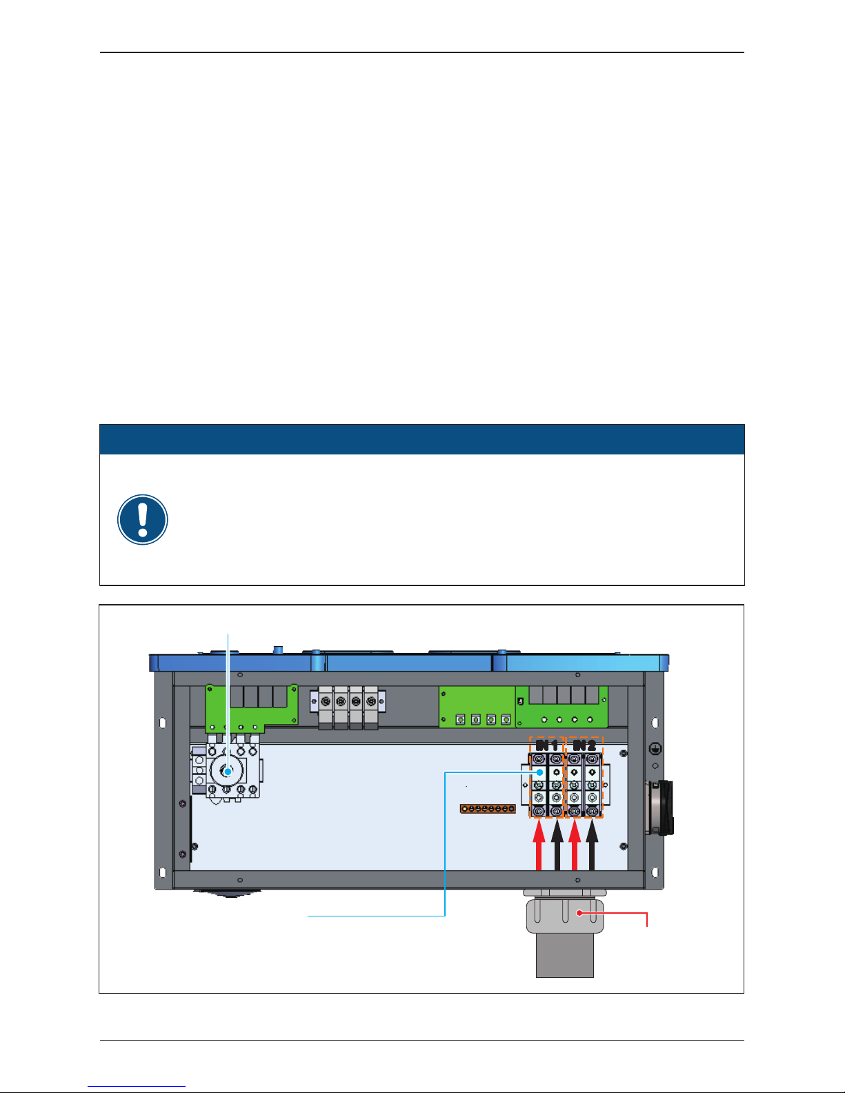
Installation

Figure 3-12 illustrates the location of the AC conduit entry and connections for
AC terminal block:
- Open all AC switch cage-clamps as noted in Section 3.3.4
- Ensure the correct conductor is connected to the appropriate terminal.
- After conductor is inserted, tighten L1~N terminal with a torque value of 24
lbf-in (2.8 N.m), PE terminal with 31 lbf-in (3.5 N.m).
3.3.5 AC Wiring for all models
Figure 3-12: Location of AC terminals and wiring (all versions)
Torque 24 lbf-in (2.8 N.m)
to fix the screw
AC switch (Terminal)
31 lbf-in (3.5 N.m)
to fix the screw
2" cable gland for AC
with EMT
EMT
36
Installation

DANGER: ELECTRICAL HARZARD!!
- PV array converts sunlight into electric power with high DC voltage and high
DC current which can cause dangerous electrical shock hazard!
- Use an opaque material to cover the PV array before wiring or cabling.
- Ensure the correct polarities are connected when DC cabling is applied.
WARNING !
- The risk of electric shock and fire.
- Use only PV modules that are UL Listed to1000V or higher.
- Ensure the two DC switches are placed in the "OFF" position, and the PV array
is disconnected when DC conductors are connected.
3.4 Electrical Installation for DC Wiring
- The PV Array current carrying conductors (positive or negative) must not be
referenced to ground.
ATTENTION
- In order not to damage the components in the inverter, don’t repeat to change
the status of DC Switch quickly, the correct operation is waiting for the LCD
display show ”No DC” or turn on the switch after 1 minute later.
CAUTION: DC SWICH ON/OFF !
Please seal the conduit from inside the wiring box
by using duct seal to prevent living creature or
moisture enter the wiring box.
ATTENTION
EMT
Duct Seal
37
Installation

Figure 3-13: Location for DC terminals for 120 models
IN 1
IN 2
IN 1 IN 2
EMT
1½ " cable gland for DC with EMT
Stripping length: 10~11mm [0.40~0.43in]
Conductor cross-section: 12~10 AWG (4~6 mm²)
Torque 16 lbf-in (1.8 N.m) to fix the screw
½" Opening for PE
2" cable gland for DC with EMT
- Ensure all fuse holder terminals are tightened to the specified torque value of
16 lbf-in (1.8 N.m).
ATTENTION
• Ensure the DC conductors used are Cu and sized to the correct ampacity per
NEC or other local code
• Strip off all wires for 10~11 mm [0.4~0.43 in].
• The cross-sectional area for each DC conductor is 12~10 AWG.
• Ensure the fuse holder terminal clamp is open
• Ensure correct conductor is connected to the correct fuse holder.
• Tighten each individual screw terminal screw to a torque value of 16 lbf-in
(1.8 N.m).
• Two 2” chassis access holes (KOs) can be utilized to connect conduits from
PV array DC wiring into the inverter, as shown in Figure 3-13.
• 120 models is compatible with 1000V/20A UL listed fuse.
Please read the following instructions for connecting DC terminals (120 models):
3.4.1 DC Wiring Installation for 120 models
AC Switch
Input 1 Fuse holders Input 2 Fuse holders
38
Installation
• These models are designed to be utilized with external combiner boxes and
are not provisioned with internal DC combining capability.
• Specific size of DC conductors must be determined from NEC or other local
codes.
•
The range of conductor sizes accommodated by each DC terminal is 8~2 AWG.
• Ensure the correct conductor is connected to its associated terminal.
•
Tighten each terminal block screw to a torque value of 8AWG - 40lbf-in (4.5N.m)
; 6~2 AWG - 110 lbf-in (12.4 N.m).
• The bending space is 160 mm [6.3in] which meets the safety standard.
• For the 121 model, two mounting options for installing the DC connection are
available, bottom or side entry; both options have a 2" chassis access hole
(KO). Side entry is shown in Figure 3-14.
Please read the following instructions for attaching DC terminals (121 models):
3.4.2 DC Wiring Installation for 121 models
Ensure the DC terminal block screws are tightened to a torque value of
8AWG - 40 lbf-in (4.5 N.m)
6~2AWG - 110 lbf-in (12.4 N.m)
- For aluminum cable :
Min./max. Conductor cross-section 10 / 33.6 mm
2
Tightening torque 110 lbf-in (12.4 N.m)
ATTENTION
Figure 3-14: Location for DC terminals for 121 models
IN 1 IN 2IN 1 IN 2
DC Terminals
Stripping length: 17mm [0.67in]
Conductor cross-section: 8~2AWG(8~33.6mm²)
Torque: 8AWG
-
40 lbf-in (4.5 N.m)
6~2AWG
-
110 lbf-in (12.4 N.m)
AC Switch
EMT
2" cable gland for
DC with EMT
39
Installation

Please follow the following guideline for cabling if you use aluminum cables.
Guideline for aluminum conductor :
- The oxide layer must be removed from the surface of the stripped aluminum
conductor.
- The stripped aluminum conductor is greased with Vaseline or contact grease
with comparable properties after oxide layer removed.
- Tightened with the maximum tightening torque for the modular terminal block.
- The installation location must be kept free from humidity or aggressive
atmospheres.
- It is recommend to apply to sector-shaped single-strand conductor ;
The conductor shape must match the sector-shaped connection
Figure 3-15: Guideline for aluminum conductor
match the sector-shaped of the connection
SE
Sector-shaped
single-strand
90°
40
Installation

Figure 3-17: DC Wiring illustration
Please read the following instructions for connecting DC terminals (122 models):
• It is important to choose the proper size for DC cable.
• The cross-sectional area for each internal cable is 12~10 AWG (4~6mm²).
DC wiring polarities are divided into positive and negative, which is shown in
Figure 3-17. The connection shall be coherent with the indication marked on
inverter.
3.4.3 DC Wiring Installation for 122 models
Figure 3-16: Location for DC terminals for 122 models
+
-
IN 1 IN 2IN 1 IN 2
PV-KST 4/6 Ⅱ
PV-KBT 4/6 Ⅱ
+04 +05 +06+01 +02 +03 -01 -02 -03 -04 -05 -06
Fuse Board 1
+04 +05 +06+01 +02 +03 -01 -02 -03 -04 -05 -06
Fuse Board 2
+01
-01
+03
-
03
+05
-
05
+02
-
02
+04
-
04
+06
-
06
+01
-01
+03
-
03
+05
-
05
+02
-
02
+04
-
04
+06
-
06
IN 1
IN 2
IN 1 IN 2
41
Installation

3.4.4
Ground bar locations for 120/121 models
Figure 3-18: Ground bar location for 120/121 models
Figure 3-18 shows the AC/DC grounding bar locations for the 120/121 models.
The wire gauge of the ground cable: 6AWG~4AWG
Torque grounding cables to 26 lbf-in (3 N.m)
-120 Model WB
-121 Model WB
42
Installation
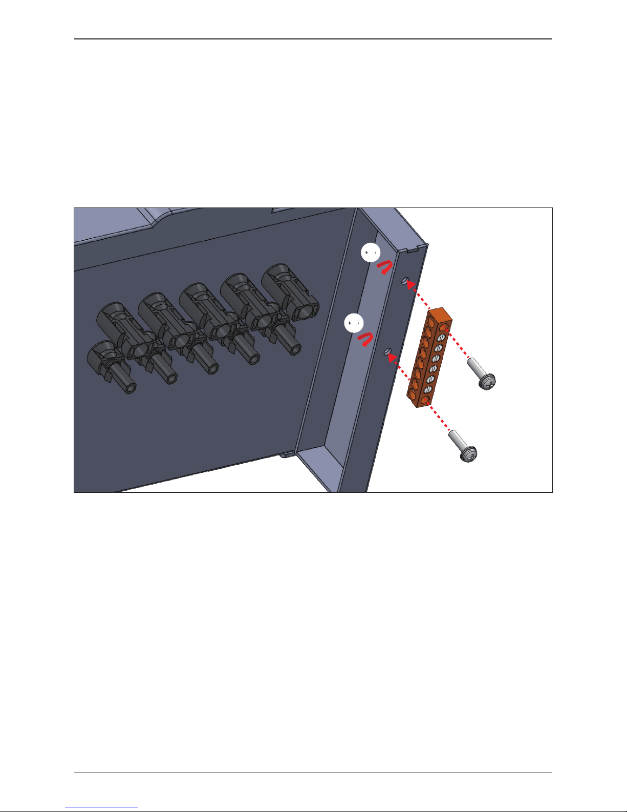
3.4.5 DC side ground bar for 122 models
Figure 3-19: Mounting the DC side ground bar to WB
After installing the unit, locate the ground bar and associated screws in accessory
bag. Be sure to orient the ground bar as shown in Figure 3-19. Torque the mounting
screws to: 22 lbf-in (2.5 N.m)
The busbar accommodates grounding conductors in the range of 6AWG~4AWG
Torque grounding conductors to 26 lbf-in (3 N.m)
①
①
②
②
②
②
43
Installation

The communication module of M42/36/28U is shown in Figure 3-20.
It provides VCC, RS-485, dry contact, EPO, and Digital Input terminals for use
in various applications. Details for each are presented below. There's a 12VDC
source between VCC & GND for use with external device.
3.5 Communication Module Connections
Figure 3-20: Communication Module Layout
Dry Contact
VCC & RS-485 EPO*1 &
Digital Inputs*6
Terminal Resistor
44
Installation

The communication module consists of an assembly with a PCB and a plastic
carrier. It is located in a slot through the bottom of the wiring box chassis.
It is accessed from the bottom exterior of the wiring box. The carrier is secured
to the chassis by two self-retaining screws. See Figure 3-21.
To access the communication module, loosen the two self-retaining screws to
loosen the carrier from the chassis. Once loosened completely, the card/carrier
module can be withdrawn from the wiring box chassis by gently pulling the
carrier straight out from the chassis.
After pulling the desired signal cable(s) through the wiring gland provided or a
connected conduit, and connected electrically as shown in the following sections,
the module can be reinstalled by reversing the above directions. Ensure the
assembly is oriented into the chassis so as to allow the edge connector to
engage properly.
3.5.1 Accessing the Communication Module
Figure 3-21: Location and access to Communication Module
* Screw torque required for assembling:
7 lbf-in (0.8N.m)
45
Installation

The pin definition for the RS-485 terminal block is shown in
Table 3-1.
- Pins 1 and 2
provide a 12DC bus for use with accessories such as R3 Power Monitor.
- Pins 3 and 5 are both connected to the DATA+ input.
- Pins 4 and 6 are both connected to the DATA
-
input.
These connections allow easy daisy-chaining of multiple inverters.
A 120 ohm bus termination resistor and associated control switch are located
on the communication board (See Figure 3-20) The switch function is as shown
in Table 3-2.
Different RS-485 connection scenarios require different set up for the 120 ohm
bus termination resistor.
•
When several inverters are cascaded (i.e., "daisy-chained") only the last inverter
in the chain must have its bus termination resistor switched ON. Refer to
Figure 3-22.
•
If the length of any RS-485 bus is greater than 2000' (610m), the use of Belden
3105A cable (or eq.) is recommended to insure communication quality.
(When using R3 Monitor, a 4-wire cable is required; Belden 3108A (or eq.) is
recommended.)
3.5.2 RS-485 Connection
Pin Function
1 VCC (+12V)
2 GND
3 DATA+
4 DATA-
5 DATA+
6 DATA-
Table 3-1: Definition of RS-485
1 2 3 4 5 6
In order to have good transfer quality, twisted-pair wire is recommended to be
used as communication cable.
ATTENTION
46
Installation

Figure 3-22: Multiinverter connection illustration
Data Format:
Baud rate: 19200
Data bits: 8
Stop bit: 1
Parity: N/A
RS485/USB
or
RS485/RS232
Terminal Resistor
(Last inverter in chain must have
Switch 2 in ON position.)
Switch 1
Terminal Resistor ON
Terminal Resistor OFF
OFF
ON
Table 3-2: Terminal resister setting
47
Installation
The communication Module has an emergency power off function (EPO), and
EPO enable can be found in the Install Settings page.
Once enabled, the EPO function can be used to turn off the inverter via a NO
relay contact connected across terminal [V1 & K0]
Additionally, a digital power reduction control is available that can be set to
limit the inverter's available active output power. The control settings for this
function are made by placing a hardware short (jumper or relay) between two
terminals of the terminal block shown in Table 3-3, below.
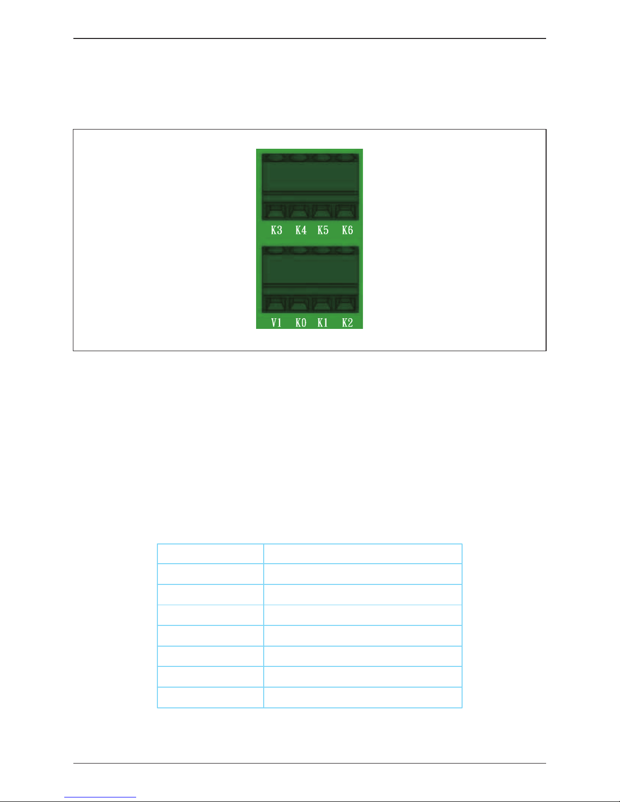
3.5.3 EPO Function & Digital Input
Figure 3-23: EPO function terminal block
Table 3-3: Definition of EPO function & Digital input
Inverter’s action
Emergency power off (EPO)
0% active power
Maximum 30% rated power
Maximum 60% rated power
Maximum 100% rated power
Reserved
Reserved
Short terminals
V1 & K0
V1 & K1
V1 & K2
V1 & K3
V1 & K4
V1 & K5
V1 & K6
48
Installation

The M42/36/28U series provides a dry control contact pair that may be used
to control external devices based on the status of operation of the inverter.
The terminal block for this function is shown in Figure 3-24. The terminals marked
in the figure identify the dry contact connection. The operation of the dry contact
is normally open. The functionality of this contact can be customized by users via
settings available in the Settings Menu.
3.5.4 Dry Contact connection
Figure 3-24: Dry Contact connection
Dry Contact
Position Not used
49
Installation

For customers who want to do on-site insulation test, please make sure:
1. The DC switches are in “OFF” position.
2.
Apply one probe to the positions shown in Figure 3-25, the other to the ground.
It might cause damages to the inverter if probes are applied to inappropriate
positions.
3.6 On-site insulation test
Figure 3-25: Precautions for on-site insulation test
-120 Model WB
-121 Model WB
-122 Model WB
Hi-pot / InsulationHi-pot / Insulation
Hi-pot / Insulation
or
DC Switch
OFF
or
DC Switch
OFF
Hi-pot / InsulationHi-pot / Insulation
or
DC Switch
OFF
50
Installation

4 Commissioning
- Be careful of hot surfaces when operating the product!
- Do not perform any task until the unit cools down or appropriate personal
protection gear is worn.
CAUTION: HOT SURFACES, DO NOT TOUCH!
4.1 Display Operation Introduction
M42/36/28U series include a front panel 4x20 character LCD display which
includes four programming keys and 2 LEDs (located on the left-hand side of
the LCD) that allow visual display of the inverter’s data and status as shown in
Figure 4-1. Please refer to Table 4-1 for information as to the information
provided by the LED indicators.
Access to various screens and the adjustment of inverter settings are done using
the LCD screen and the four programming buttons directly below the LCD screen,
See Table 4-2 for programming descriptions of operation.
When adjusting settings, LCD panel will change the display cursor from “►” to
“ ”
Figure 4-1: Front Panel Display
LED Indicator (RED)
LED Indicator (GRN)
EXIT: Exit Menu
Down: Move Down
UP: Move UP
ENT: Enter Menu or Confirm
LCD screen
51
Commissioning

Condition Green LED Red LED
Countdown FLASH * OFF
Power ON ON OFF
Error or Fault OFF ON
Standby or Night time (No DC) OFF OFF
Bootloader mode FLASH *
* ON 1s / OFF 1s
Table 4-1: LED indicator
Table 4-2: Programming keys and actions
Symbol Action
ENT Enter a Menu or Confirm a programmed value
▲ Move cursor UP in menu or increase a programmed value
▼ Move cursor Down in a menu or decrease a programmed value
EXIT
Button
Enter
UP
Down
Exit Exit Menu
52
Commissioning

The following sections indicate inverter status and settings as shown on the LCD
display.
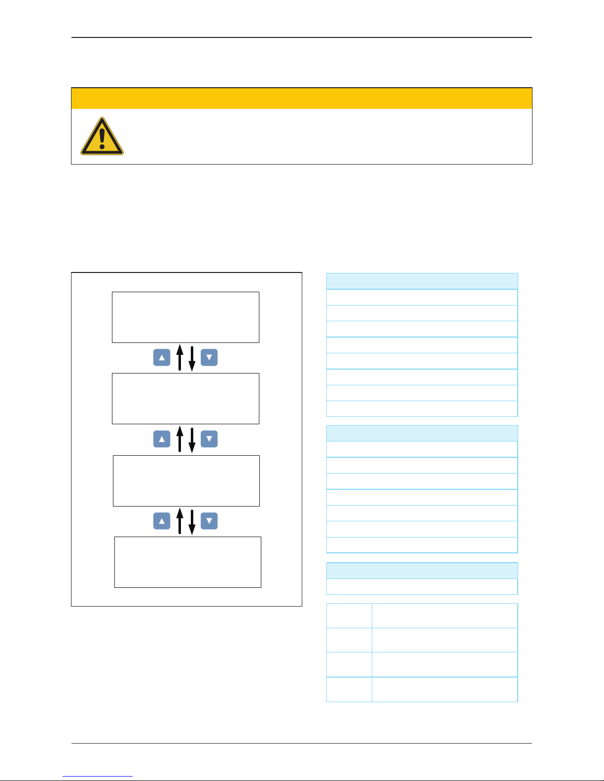
4.2 First startup
Figure 4-2: Grid code, language and ID settings for first startup
Are you sure to
set Grid Code ::
IEEE1547 480V
Yes / ► No
Are you sure to
set protocol :
Delta prot.
Yes / ► No
Are you sure to set
ID : 1
Yes / ► No
Select Grid Code,
1741 SA-277V
IEEE1547 480V
IEEE1547.A 480V
►
Select Language,
English
Deutsch
Français
►
Setting ID:
ID = 001
Pass: to Home page
Fail: to Home page but in locked status
and indicated“AFCI fail”
06. Oct 2018 15 : 33
AFCI
Self Testing . . .
AFCI Self Test
Result: Pass
When setting is
IEEE1547
Delta prot.
Sunspec prot.
EXIT
ENT
EXIT
ENT
ENT
►
* AC Connection: 3P3W is factory default; see Section 4.3.7.9 for further details.
Yes / ►No
EXIT
ENT
EXIT
ENT
EXIT
ENT
EXIT
ENT
EXIT
ENT
At the time of initial startup, a First Start routine is started allowing user to set
basic functions without need of a password. An appropriately sized PV array and
an AC grid must be available and connected to the inverter. Procedure is as follows:
• Complete the appropriate system pre-commissioning procedure(s).
• Initially, ensure both DC switches are in OFF position, and interconnect the
inverter to the AC grid by turning on internal and any external AC switches as
required.
• Verify the inverter control system is powered by noting that the LCD display
panel has become active.
• During the initial startup, when the LCD display become active, the inverter
control will enter the First Start-up routine which allows installer to set Language,
Grid code, RS-485 protocol and inverter ID (RS-485 address). Figure 4-2 below,
illustrates the display flow charts of the inverter startup.
• Using display and programming keys, set desired language and the country
(Grid Code) associated with the installation location and wait for the AFCI Self
Test to complete.
• Verify AFCI self test result is a pass.
• Close both DC switches, and await inverter to complete its self test sequence,
which takes approximately two minutes.
•
Verify via the display there are no errors, faults or warning indications displayed
on the home page.
• If there is sufficient power available from PV array, inverter will connect to grid
and begin exporting power to the grid.
53
Commissioning

4.2.1 Home Page
Figure 4-3: Home Page screen
21 Jan. 2016 16:30
Status: :
Power:
E-Today:
42000 W
147 kWh
On Grid
Inverter Status
Output Power
Today Energy
Day -Time
After completion of First Start and inverter is in normal operation, the LCD will
display the homepage screen as shown in Figure 4-3. The user can view
information to include output power, inverter status, E-today, date and time.
Pressing "any" key in home page mode will open the main menu. To return to
Home Page screen, press EXIT at main menu or wait 5 minutes without any
key operation, the display will return to homepage.
Table 4-3 contains is a listing of all inverter functions that can be adjusted by
users (U) and installers (I) via the LCD panel, and the associated manual
subsection where a description of the operation of each is found.
4.3 Main Menu
Table 4-3: Inverter Functions
Function Para
Power Meter 4.3.1
Energy Log
String Current Mon
4.3.2
Event Log
4.3.3
Information
4.3.4
General Settings
4.3.5
Inverter ID
4.3.7
Insulation
4.3.7.1
4.3.7.2
Grid Code 4.3.7.3
Install Settings
4.3.6
Access
U,I
U,I
U,I
U,I
U,I
I
I
I
I
U,I
I
I
I
I
I
I
I
I
I
I
Function Para
Grid Settings 4.3.7.4
Dry Contact Set-up 4.3.7.5
PID 4.3.7.6
RCMU 4.3.7.7
AC Connection 4.3.7.9
Emergency Power-Off 4.3.7.8
AFCI 4.3.7.11
Grid code confirm 4.3.7.12
Active / Reactive power 4.3.8
Anti-Islanding 4.3.7.10
Access
54
Commissioning

This page displays voltage, current and power measurements from both the
AC and DC side.
4.3.1 Power meter
4.3.2 String monitoring (120&122 models)
Figure 4-4: Power Monitoring and String Current Monitoring
V 480
I 50.5
P 13989
480
50.5
13989
480
50.5
13989
L1 L2 L3AC
Power.
Frequency::
E-Today:
PF
41966
0.9
60.00
147
kW
Hz
kWh
V 545
I 40.0
P 21800
545
40.0
21800
DC1 DC2DC
or
V
A
W
V
A
W
ENT
or
ENT
or
ENT
1:
2:
3:
8.0
8.1
7.9
4:
5:
6:
8.0
8.1
8.0
1:
2:
3:
8.0
8.1
7.9
4:
5:
6:
8.0
8.1
8.1
IDC1 (A)
IDC2 (A)
or
ENT
The string current monitoring function is accessed via the Power Meter menu
Four sub-pages are accessed using display keys as shown in Figure 4-4, two
pages display string current values for the nine strings of MPPT1 and MPPT2.
55
Commissioning

User can view the inverter’s lifetime energy runtime via Energy Log page.
4.3.3 Energy Log
Event Log display has two sub-pages as noted below and shown in Figure 4-6:
• Error Events page displays all the events (Error and Fault) and can show 30
records at a time.
• Grid Report page only displays the error that occurred at grid side, and it can
show 5 records at a time.
4.3.4 Event Log
Figure 4-5: Energy Log screen
Figure 4-6: Event Log screens
Life Energy
Day Energy
Month Energy
►
Life Energy:
E-Total:
Runtime:
30680.02 kWh
7302 Hrs
Life Energy
Day Energy
Month Energy
►
Life Energy
Day Energy
Month Energy
►
EXIT
ENT
Day Energy:
2016.10.10
2016.10.09
2016.10.08
147 kWh
146 kWh
145 kWh
EXIT
ENT
Month Energy:
2016.10
2016.09
2016.08
4410 kWh
4409 kWh
4408 kWh
EXIT
ENT
1. 20/01/2016 15:30
AC Freq High
2. 19/01/2016 09:30
AC Volt Low
29. 18/01/2016 15:30
AC Freq High
30. 17/01/2016 09:30
AC Volt Low
or
or
Error Events
Grid Report
►
Error Events
Grid Report
►
1. 20/01/2016 15:30
AC Freq High
2. 19/01/2016 09:30
AC Volt Low
5. 18/01/2016 15:30
AC Freq High
or
or
Press ▲,▼&ENT > 5s
Clear Event Logs ?
Yes / ► No
Empty
Yes
No Event
Press ▲,▼&ENT > 5s
Clear Event Logs ?
Yes / ► No
Empty
Yes
No Event
EXIT
EXIT
EXIT
EXIT
ENT
ENT
ENT
ENT
ENT
ENT
56
Commissioning

This page allows the user to view static data associated with the inverter to
include serial number, installation date, inverter ID (RS-485 address), and
firmware version. Additional parameters are accessed via connected menus
using the up/dn keys. Programmed settings (e.g., Inverter ID, baud rate) are
adjusted using the settings menu. The complete list of inverter information
items can be seen in Figure 4-7, below.
4.3.5 Inverter Information
Figure 4-7: Inverter information screens
This page allows the setting of Language, Date and Time, and RS-485 baud
rate via sub-menus. Use UP/DN arrow keys to navigate to desired sub-menu,
and then press ENT to enter the chosen sub-menu.
4.3.6 General Settings
Figure 4-8: General Settings screen
S/N: RN11179CB0
Install: 01/01/2016
INV ID: 1
AC connection:
Max. Power:
Dry Cont A:
Dry Cont B:
3P3W
46000W
Disable
Disable
FW Version
DSP:
COM:
SCM:
1.30
91.05
1.35
RED:
ARC:
61.06
1.05
►
EPO Normal Open
Grid Settings
Active Pwr Settings
React Pwr Settings
or
ENT
or
ENT
or
ENT
►
EPO Normal Open
Grid Settings
Active Pwr Settings
React Pwr Settings
►
EPO Normal Open
Grid Settings
Active Pwr Settings
React Pwr Settings
FRT Settings
or
ENT
Country:
Insulation:
Baud Rate:
IEEE1547 480V
100
k
19200bps
►
Language
Date and Time
Baud Rate
Protocol
►
57
Commissioning
4.3.7 Install Settings
To enter Install Settings page, users must enter a valid password, which must
be obtained from Delta Electronics. There are three sets of password with
different permissions: User Level, Installer Level, and Manufacturer Level.
The following sub-sections will introduce the parameters settings accessible from
the User and Installer level menus of the Install Settings page.
Figure 4-9: Install settings Display screens
Table 4-4: Controls Access Levels
- Changing the settings in the Install Settings page can result in damage to
the inverter and other equipment. These settings must only be adjusted by
qualified installers or engineers.
CAUTION !
AFCI* ON
Return to Factory
►
EPO*
AC Connection
Anti-islanding
Max. Power
►
Normal Open
3P3W
ON
46000W
DC Injection
Dry Cont.
PID Function*
RCMU*
►
Insulation
ON
Inverter ID: 1
Insulation
Grid Code
Grid Settings
►
- Inverter ID
User Level:
- Insulation
- Grid Code
- Dry Contact
- PID Function*
- EPO*
*PID
*RCMU
*EPO
*AFCI
Potential Induced Degradation
(see section 4.3.7.6)
Residual Current Monitoring
(see section 4.3.7.7)
Emergency Power Off function
(see section 3.5.3)
DC arc fault current interrupter
(see section 4.3.7.11)
- Max. Power
- AC Connection
- All above User Level plus
Installer Level:
- Grid Settings
- Active Power Settings
- Reactive Power Settings
- DC Injection
- RCMU*
- Anti-Islanding
- All above Installer Level Settings
Manufacturer/Factory Level:
58
Commissioning
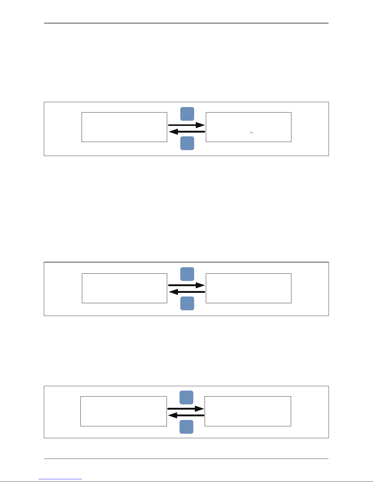
Figure 4-10: Inverter ID screen display
Figure 4-11: Insulation screen display
Inverter ID is the RS-485 address which is assigned to the inverter and used
when the RS-485 communication system is operating, e.g., connected to a PC
or data logger. If several inverters are connected to the RS-485 bus, each must
have a distinct Inverter ID. Allowable ID values are 1-254. Consult data logger
manufacturer to determine maximum number of inverters on a single RS-485 bus.
Prior to connecting to grid, the inverter control will measure the impedance
between the floating PV array(s) and ground (PE), also known as isolation
resistance, RISO. This measurement is compared to an internal limit and used
to determine if any ground fault is present in the array prior to connection of the
inverter to the grid.
The inverter will not connect to the grid if the measured resistance is smaller
than 100kΩ.
4.3.7.1 Inverter ID
4.3.7.2 Insulation
Setting ID:
ID = 0
02
Inverter ID: 1
Insulation
Grid Code
Grid Settings
►
EXIT
ENT
Mode: ON
Resistance: 100kΩ
►
ON
DC1 only
DC2 only
OFF
►
EXIT
ENT
The grid code setting is used to program the inverter control system to be
consistent with the grid voltage, frequency and basic grid configuration of the
country or locale where installed. In NA, the grid code setting is IEEE 1547 480V.
4.3.7.3 Grid Code
Inverter ID: 2
Insulation
Grid Code
Grid Settings
►
►
1741 SA-277V
IEEE1547 480V
IEEE1547.A 480V
HECO A
EXIT
ENT
Figure 4-12: Grid Code screens
59
Commissioning

4.3.7.4 Grid Settings
Figure 4-13: Grid Settings screens
Inverter ID: 2
Insulation
Grid Code
Grid Settings
►
Voltage Protection
Freq. Protection
Reconnect T
P Ramp Up
►
High Off
High On
High Off T
Low Off
►
575.0V
523.0V
0.1s
240.9V
Low On
Low Off T
Hi Off Slow
Hi On Slow
►
427.9V
0.1s
526.0V
523.0V
Hi Off Sl T
Lo Off Slow
Lo On Slow
Lo Off Sl T
►
1.0 s
421.9V
427.9V
2.0 s
Voltage Protection
Freq. Protection
Reconnect T
P Ramp Up
►
High Off
High On
High Off T
Low Off
►
62.05Hz
60.50Hz
0.1s
57Hz
Low On
Low Off T
Hi Off Slow
Hi On Slow
►
57.05Hz
0.1s
65.00Hz
64.95Hz
Hi Off Sl T
Lo Off Slow
Lo On Slow
Lo Off Sl T
►
5.0s
57.00Hz
57.05Hz
300 .0s
600s
6000%/m
600s
6000%/m
If user enters wrong settings
Wrong Settings
If user enters wrong settings
Wrong Settings
Press ▲&▼ 5s
Do you want to set
U to the max range?
Yes / ►No
Do you want to set
F to the max range?
Yes / ►No
Press ▲&▼ 5s
EXIT
EXIT
EXIT
EXIT
EXIT EXIT
EXIT
EXIT
ENT
ENTENT
This menu item allows the installer or an engineer to enable and/or adjust specific
"smart inverter" (aka, CA Rule 21 or HECO functionality) grid parameters to
include low/high voltage ride-through(L/HVRT), low/high frequency ride-through
(L/HFRT), Soft start and ramp rates. Refer to Figure 4-13. Further details of this
functionality is provided in Appendix A and B.
60
Commissioning
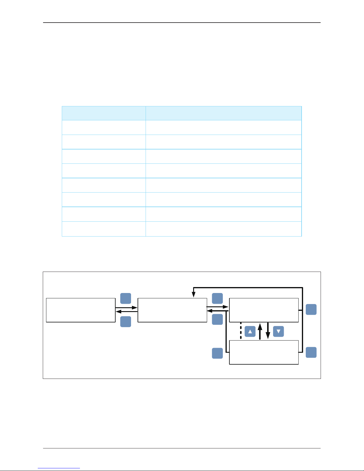
4.3.7.5 Dry Contact Set-up
Dry Contact Trigger Timing
No action.
Inverter is connecting to grid.
Fan Fail occurs.
Insulation test fail.
Any error, fault, or warning occurs.
Any Error occurs.
Any Fault occurs.
Setting
Disable
On Grid
Fan Fail
Insulation
Alarm
Error
Fault
Any Warning occurs.Warning
Table 4-5: Dry Contact Trigger Options
Figure 4-14: Dry Contact screens
EXIT
EXIT
EXIT
ENT
ENT
ENT
ENT
DC Injection
Dry Cont.
PID Function
►
RCMU ON
►
Alarm
Error
Fault
Warning
►
Disable
On Grid
Fan Fail
Insulat.
Dry Cont. A
Dry Cont. B
Disable
System provide a dry contact to allow users to create a hardwired control, Users
can choose the trigger condition of the dry contact. There are 8 options in the settings
page: Disable, On Grid, Fan Fail, Insulation, Alarm, Error, Fault, and Warning.
Please refer to Table 4-5 for more details about these options.
61
Commissioning
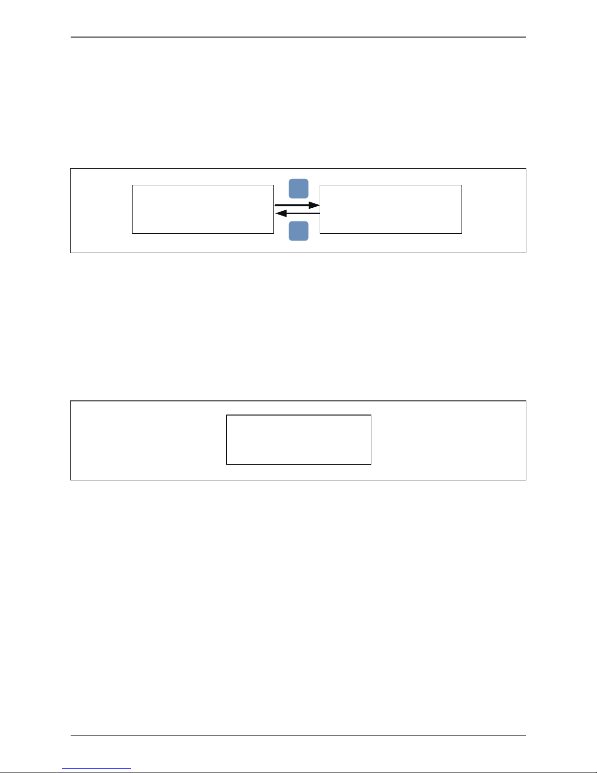
4.3.7.6 Potential Induced Degradation
4.3.7.7 Residual Current Monitoring Unit (RCMU)
4.3.7.8 Emergency Power-Off Enable
RCMU (Residual Current Monitoring Unit) monitors DC and AC residual current
and inverter is disconnected from grid when residual current is high enough.
The default setting of RCMU is “ON”.
The inverter has an Emergency Power-Off function (EPO), which once enabled,
can be used to turn off the inverter via an external control signal.
See Section 3.5.3 for additional details.
Figure 4-15: PID function Display screens
Figure 4-16: RCMU screen
DC Injection
Dry Cont.
PID Function
RCMU
►
ON
Time:
►
1 Hours
EXIT
ENT
DC Injection
Dry Cont.
PID Function
RCMU
►
ON
PID (Potential Induced Degradation) is a phenomenon which puts a high level
negative voltage on PV module and make PV module performance low.
The default action time of PID is set with 0(it means disable PID function), user
can set the time from 0-10 Hours or Auto. It will be started the function at 30
minutes after No DC, and will be stop the function when DC voltage is input.
62
Commissioning
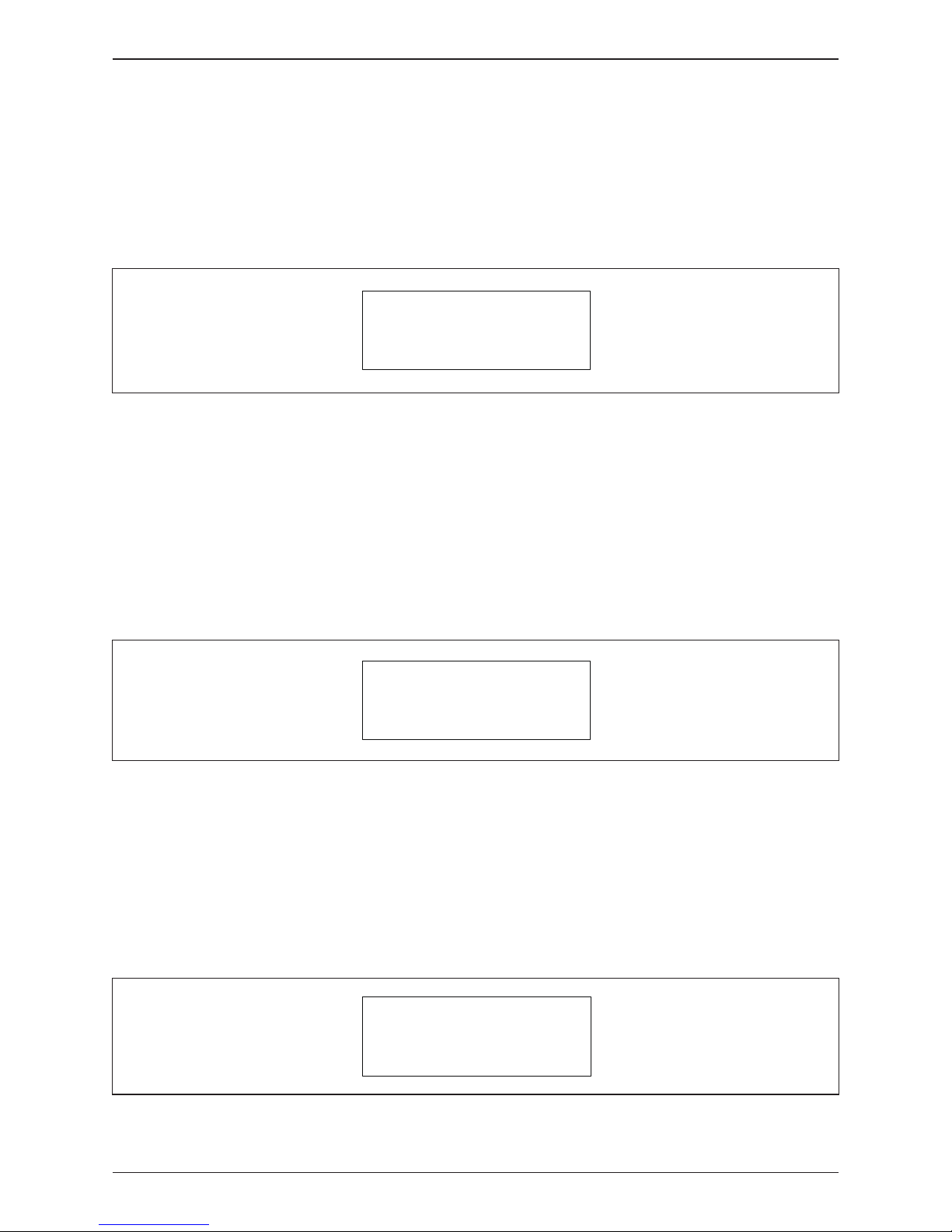
Figure 4-17: AC Connection
The AC Connection sub-menu provides user a choice of AC connections:
· 3P3W - indicates the inverter connection to an AC grid is as a 3-phase/3-wire
device (default setting) No Neutral is required.
· 3P4W - indicates the inverter connection to an AC grid is as a 3-phase/4-wire
device; Neutral connection required.
4.3.7.9 AC Connection
-islanding
Max.
EPO
AC Connection
Anti
Power
►
Normal Close
3P3W
ON
46000W
Figure 4-18: Anti-Islanding Display screen
Anti-islanding protection is a way for the inverter to sense when there is a problem
with the power grid, such as a power outage, and shut itself off to stop feeding
power back to the grid. Delta anti-islanding function is based on the Sandia
Frequency Shift algorithm. The default setting depends on grid code (always
ON in NA).
4.3.7.10 Anti-Islanding
-islanding
Max.
EPO
AC Connection
Anti
Power
►
Normal Close
3P3W
ON
46000W
Figure 4-19: DC AFCI Display screen
AFCI (Arc Fault Circuit Interrupter) is an advanced circuit breaker that breaks
the circuit when it detects a dangerous electric arc in the circuit it protects to
prevent electrical fires. The default setting of AFCI is “ON”.
4.3.7.11 DC Arc Fault Circuit Interrupter (AFCI)
AFCI
Return to Factory
►
ON
Commissioning
63

User can confirm grid code parameters as following, such as voltage and frequency
protection parameters.
More detail of F/VRT will be show in appendix.(For HECO and Rule 21).
4.3.7.12 Grid code confirm
Figure 4-20: Grid Code Confirm screens
S/N: RN11179CB0
Install: 01/01/2016
INV ID: 1
►
Meter
Energy Log
Event Log
Inverter Info.
EXIT
ENT
Country:
Insulation:
Baud Rate:
HECO A
100k
Ω
19200bps
FW Version
DSP:
COM:
SCM:
1.30
91.05
1.35
RED:
ARC:
61.06
1.05
AC connection:
Max. Power:
Dry Cont A:
Dry Cont B:
3P3W
46000W
Disable
Disable
►
EPO Normal Open
Grid Settings
Active Pwr Settings
React Pwr Settings
Commissioning
64

Figure 4-21: Active / Reactive power screens
Figure 4-22: Power Limit screens
Figure 4-23: Power vs Frequency screens
A password is required to enter Active / Reactive Power page.
This page includes two kinds of function: active power control and reactive power
control. In active power control function, there are 3 control modes:
Power Limit, Power vs. Frequency, and P(V). In reactive power control function,
there are 4 control modes: Constant cosphi, cosphi(P), Constant Q, and Q(V).
These modes will be introduced in next section.
- All function’s voltage settings used by phase voltage. -
This control mode can reduce the output power to a percentage of inverter’s
rated power. Users can limit the output power by set the Set Point in Power
Limit page.
Inverter will reduce output power when grid frequency rises up if this mode
enabled. Users can tune the parameters in Power vs. Frequency page to
change the inverter’s behavior.
Power Limit
Power vs. Frequency
P(V)
►
Mode:
Set Point:
►
ON
100%
EXIT
ENT
Power Limit
Power vs. Frequency
P(V)
►
Mode
F start
F recovery
Gradient
►
ON
60.20 Hz
60.15 Hz
100%
T recovery
►
300s
EXIT
EXIT
ENT
Active Power Ctrl
Reactive Power Ctrl
►
Warning:
Adj. would affect
energy production.
Password:
****
EXIT
ENT
4.3.8 Active / Reactive power
4.3.8.1 Power Limit
4.3.8.2 Power vs. Frequency
Commissioning
65

P
Pm
f
start =
f
(Hz)
Gradient
f
recoveryfprotection
Figure 4-24: Power vs Frequency parameter
Figure 4-25: P(V) screens
When grid voltage rises up to a lock-in voltage(V lock-in) and inverter’s present
output power is greater than lock-in power(P lock-in), inverter will reduce the
output power and keep it at a certain value(P lock-out) until grid voltage drop
back to lock-out voltage(V lock-out) and passing a certain time(T recovery).
Power Limit
Power vs. Frequency
P(V)
►
Mode
P lock-in
P lock-out
V lock-in
►
OFF
20%
5%
528.2V
V lock-out
T recovery
►
519.6V
300s
EXIT
EXIT
ENT
4.3.8.3 P(V)
Commissioning
66
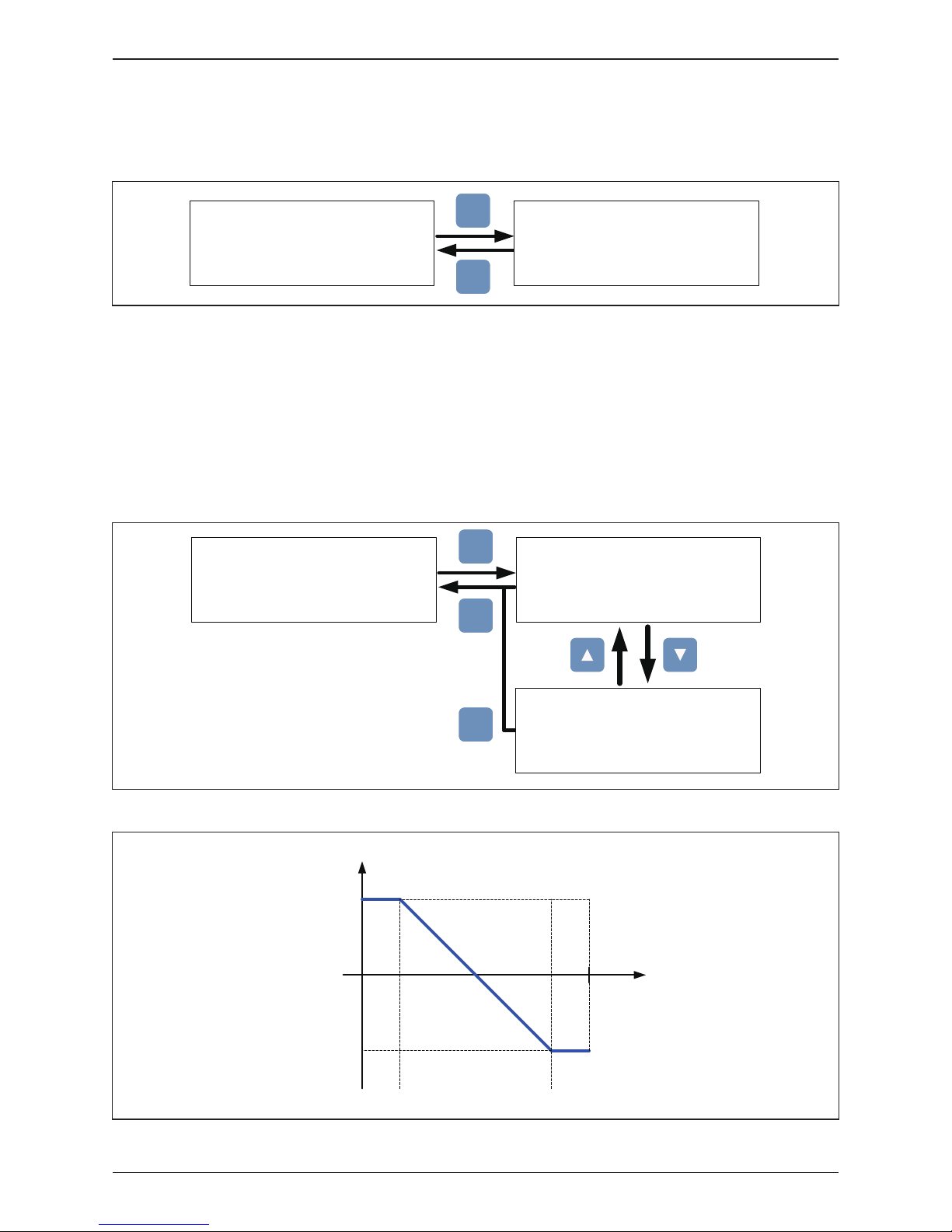
Inverter can feed in a fixed reactive power to grid. Users can set the power
factor(cosphi) in Constant cosphi page.
Cosphi (P) is a function that inverter will feed in reactive power when its output
active power reach the setting values.
When grid voltage reach the lock-in voltage(V lock-in), inverter will enable
cosphi (P) function automatically and disabled it when grid voltage reach lock-out
voltage(V lock-out).
►
Constant cosphi
Cosphi (P)
Constant Q
Q(V)
Mode
cosphi
►
OFF
Ind 1.00
EXIT
ENT
Figure 4-26: Constant cosphi screens
Figure 4-27: Cosphi (P) screens
►
Constant cosphi
Cosphi (P)
Constant Q
Q(V)
Mode
Q upper
P lower
Q lower
►
OFF
Ind 1.00
45%
Ind 0.90
P upper
V lock-in
V lock-out
►
90%
0V
0V
EXIT
EXIT
ENT
Q upper
Q lower
P/Pn
1
cosφ
P lower P upper
Figure 4-28: Cosphi (P) curve
4.3.8.4 Constant cosphi
4.3.8.5 Cosphi (P)
Commissioning
67

Figure 4-29: Constant Q screens
Figure 4-30: Q(V) screens
Like Constant cosphi function, users can assign a percentage of reactive power
in Constant Q page.
Q(V) is a control mode that inverter will provide reactive power according to
grid voltage.
►
Constant cosphi
Cosphi (P)
Constant Q
Q(V)
Mode
Fix Q
►
OFF
Ind 90%
EXIT
ENT
►
Constant cosphi
Cosphi (P)
Constant Q
Q(V)
Mode
V1s
V2s
Qs limit
►
OFF
479.7V
528.2V
Ind 44%
V1i
V2i
Qi limit
T delay
►
479.7V
403.5V
Cap 44%
10.00s
P lock-in
P lock-out
►
0%
0%
EXIT
EXIT
EXIT
ENT
4.3.8.6 Constant Q
4.3.8.7 Q(V)
Commissioning
68

►
General Settings
Install Settings
Active/Reactive Pwr
FRT
Mode
Dead Band
Vdrop
t1
►
OFF
-10%
0%
0.30s
U1
t3
K factor
►
20%
3.00s
2.0
Warning:
Adj. would affect
energy production.
Password:
****
EXIT
EXIT
EXIT
ENT ENT
V
1s
V
2s
V
1i
V
2i
Q
i limit
Q
s limit
V
Q
Figure 4-31: Q(V) parameter
Figure 4-32: FRT screens
Figure 4-33: FRT Parameter
Some area requests that inverter should keep connected to grid when grid
voltage drops suddenly in few seconds. In these areas, users can enable FRT
function and adjust the parameters to meet the requirement.
100%
U1
0
t1
Fault occurrence
t3
time
U
grid/Unom
Umin
Udrop
Disconnect from grid
Stay connected
4.3.9 FRT (Fault ride through)
Commissioning
69

5 Maintenance
Please check the unit regularly. If there are any impaired or loose parts, please contact
your solar installer. Ensure that there are no fallen objects in the path of the heat outlet.
WARNING !
- Prior to beginning any maintenance procedures switch AC and DC power off
to avoid risk of electrical shock!
Figure 5-1: Removing and reinstalling the WB cover
In order to guarantee proper long-term operation of the inverter, the following
procedures must be followed used to remove and re-install the WB cover, Refer
to Figure 5-1.
5.1
Removing and replacing the Wiring Box (WB) cover
OFFOFF
OFF
OFF
70
Maintenance

5.1.1 Removing the WB cover
• Never attempt to remove the WB cover in rainy damp weather without weather
protection around the inverter.
• Switch AC and DC power off and wait until LCD display turns off.
• Loosen the 4 screws on the WB front cover and remove cover.
• Use care not to contaminate the WB cover gasket and mating surfaces
After removing the WB cover, do not leave the WB uncovered for long
periods of time.
5.1.2 Replacing the WB cover
Before re-installing the wiring box (WB) cover:
1. Ensure mating surfaces and gasket are clean
2. The gasket is properly located and aligned in its mounting slot.
When re-installing the wiring box cover:
1. Hand tighten screws cross wise and equally.
2. Fully tighten the WB cover screws to 21 in-lb of torque (2.37N-m)
After re-installing the wiring box (WB) cover:
1.
Use care to ensure the WB cover screws are started properly and not cross-threaded.
2. After tightening, check that screw heads are flush with cover
Figure 5-2: Re-installing process for Wiring Box cover
* Attention to the orientation of the cover
71
Maintenance

M42/36/28U series models have the surge protection device (SPD) at both AC
and DC side as shown in Figure 5-3. Table 5-1 summarizes the specifications
of AC and DC SPD.
5.2 Replacement of Surge Protection Devices (SPD)
Figure 5-3: AC and DC SPD modules
Table 5-1: SPD Specifications
Description Value
AC Module
Working voltage:
DC Module
Working Current (8/20us)
Operating Ambient Temperature Range
Rated Current (IMAX – 8/20us)
895VRMS
1175VDC
10kA
-40°C to 85°C
20kA
Sichuan Zhongguang Lightning
Protection Technologies Co., Ltd
Manufacturer:
If it's necessary to remove the insulator plate
of wiring box during Cabling or maintenance,
the insulator plate must be put back in to the
wiring box before re-install the cover, refer the
figure right.
Insulator plate
WARNING !
72
Maintenance
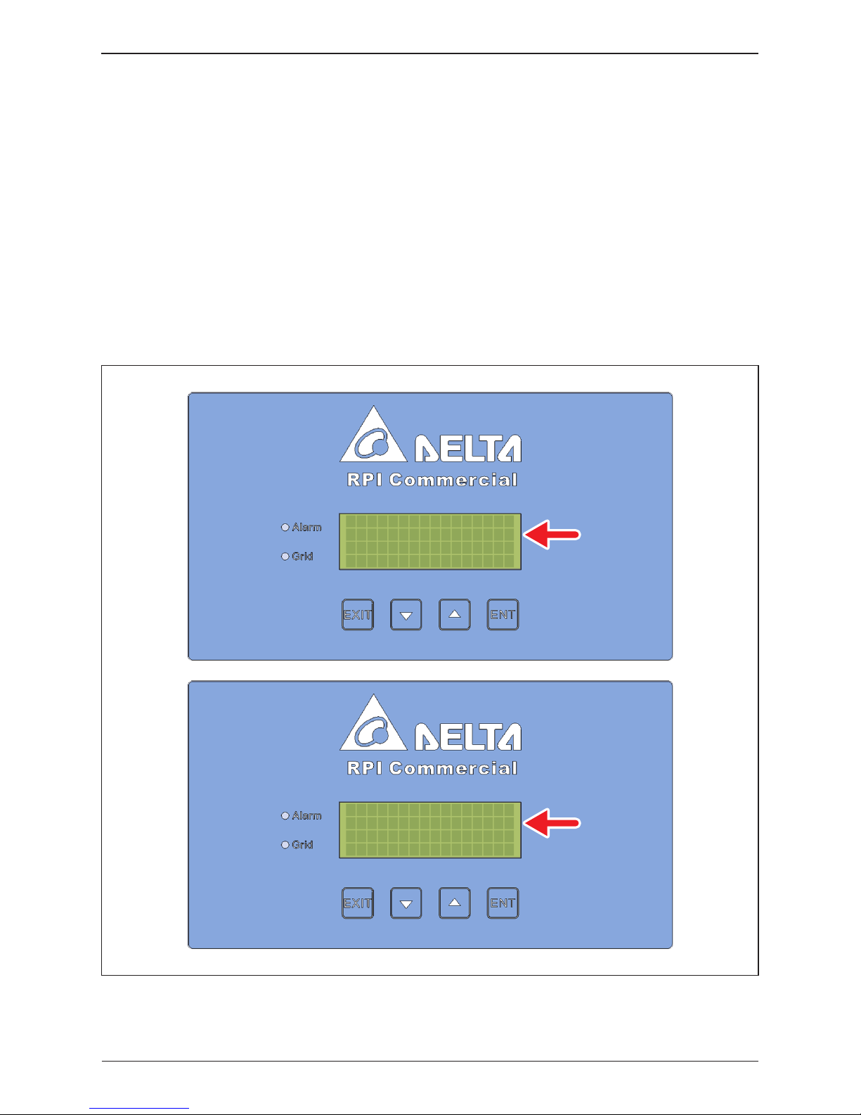
17 Mar. 2016 03:14
Status:
Power:
E-Today:
AC Surge
0kW
0kWh
17 Mar. 2016 03:14
Status:
Power:
E-Today:
DC Surge
0kW
0kWh
Surge protection devices (SPD) are designed to protect sensitive circuit
elements of the inverter from damage caused by lightning and other electrical
transients/surges, as such they are sacrificial components and periodically,
may need replacement.
The SPDs are located in the inverter wiring box (WB) on both AC and DC input
terminals. If a warning message “AC Surge” or “DC Surge” appears on display
panel, follow the procedure below to replace the SPD.
• Determine which SPD unit is damaged. See Figure 5-4.
AC SPD: “AC Surge” with show on the corner of the LCD panel.
DC SPD: “DC Surge” with show on the corner of the LCD panel.
Figure 5-4: Display Indicating AC and DC SPD failure
73
Maintenance
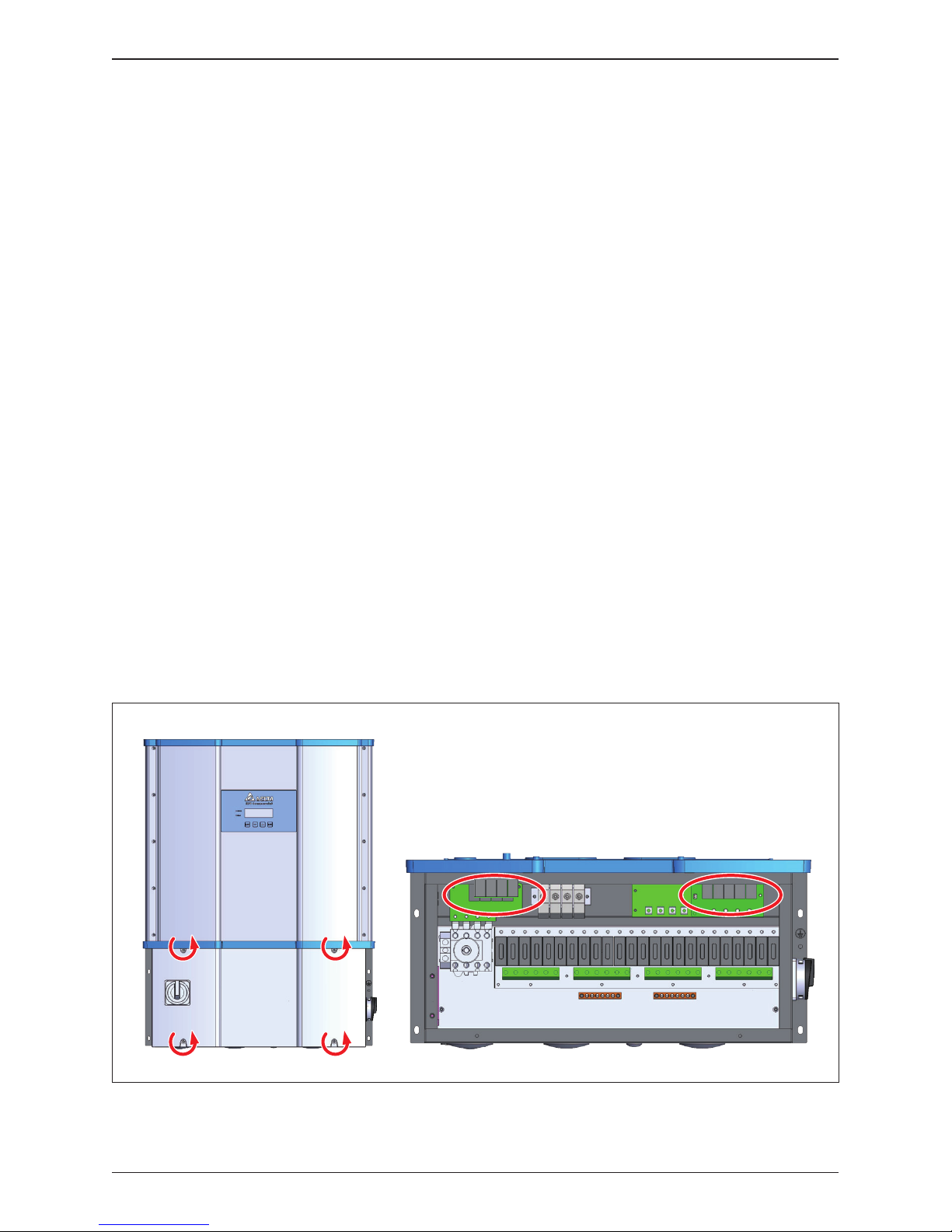
Figure 5-5: Location of SPD modules inside various WB versions
AC SPD DC SPD
• Accessing the Wiring Box
1. Switch AC and DC power off and wait until LCD display turns off.
2. To access the wiring box, use procedure found in Section 5.1.1
Do not leave the WB uncovered for long periods of time.
• Changing the SPD modules - use the following procedure:
The AC and DC SPD units are located as shown in Figure 5-5.
• To remove the defective SPD, refer to Figure 5-6
1. Disengage the white wiring connector from the SPD PCB (3-pin on AC SPD
or the 2-pin on DC SPD).
2. Remove four Phillips head screws at the front (terminal block) side of the
SPD PCB.
3. Remove the single Phillips head screw located on the left (DC) or right (AC)
side of the SPD PCB.
4. Lift and remove the entire SPD PCB and replace with new unit.
5. Install the new SPD using the above procedure in reverse order. Tighten
the five screws to a torque value of 15 lbf-in (1.7 N.m).
• Re-installing the Wiring Box cover
To re-install the WB cover, use the procedure found in Section 5.1.2
74
Maintenance
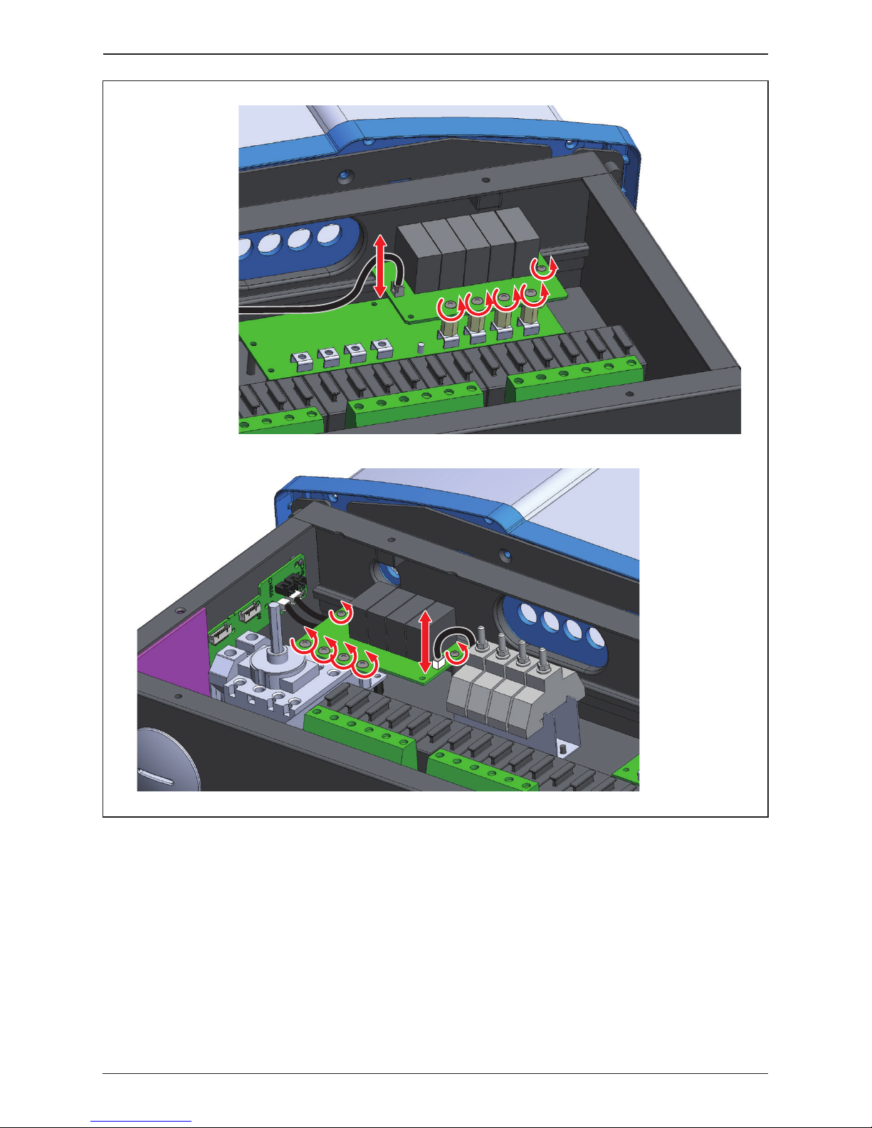
Figure 5-6: Remove screws as indicated unplug connectors
DC SPDs
AC SPDs
75
Maintenance

M42/36/28U 120 and 122 models both have a wiring box provisioned with two
independent internal string combiners, each associated with one of the two
MPPT inputs.
The combiners utilize standard 10 mm x 38 mm PV combiner fuses and associated
fuse holders. Because of the TL design, all strings are floating with respect to
ground, and two fuses are required per string input connected in series with
the positive and negative string leads.
Any 10mm x 38mm Listed PV fuse can be utilized for replacement purposes.
The specifications of the required fuse and the fuse brand utilized at the factory
are listed below.
5.3 Replace Internal String Fuse
Rated current
Rated voltage
Operating Class
Fuse Type
15 A
1000 V
Solar PV
10x38 ferrule
UL Listed
UL Listing Category
Typical Mfr
Mfr P/N
UL248-19/UL2579
JFGA
Littelfuse
OSPF015
CAUTION – Shock/Fire hazard
Fuse holders do not have load break capability!
Before opening any combiner fuse holder in -120 or -122 models be sure both
DC switches are in the OFF position
Table 5-2: Combiner Fuse Specification
76
Maintenance
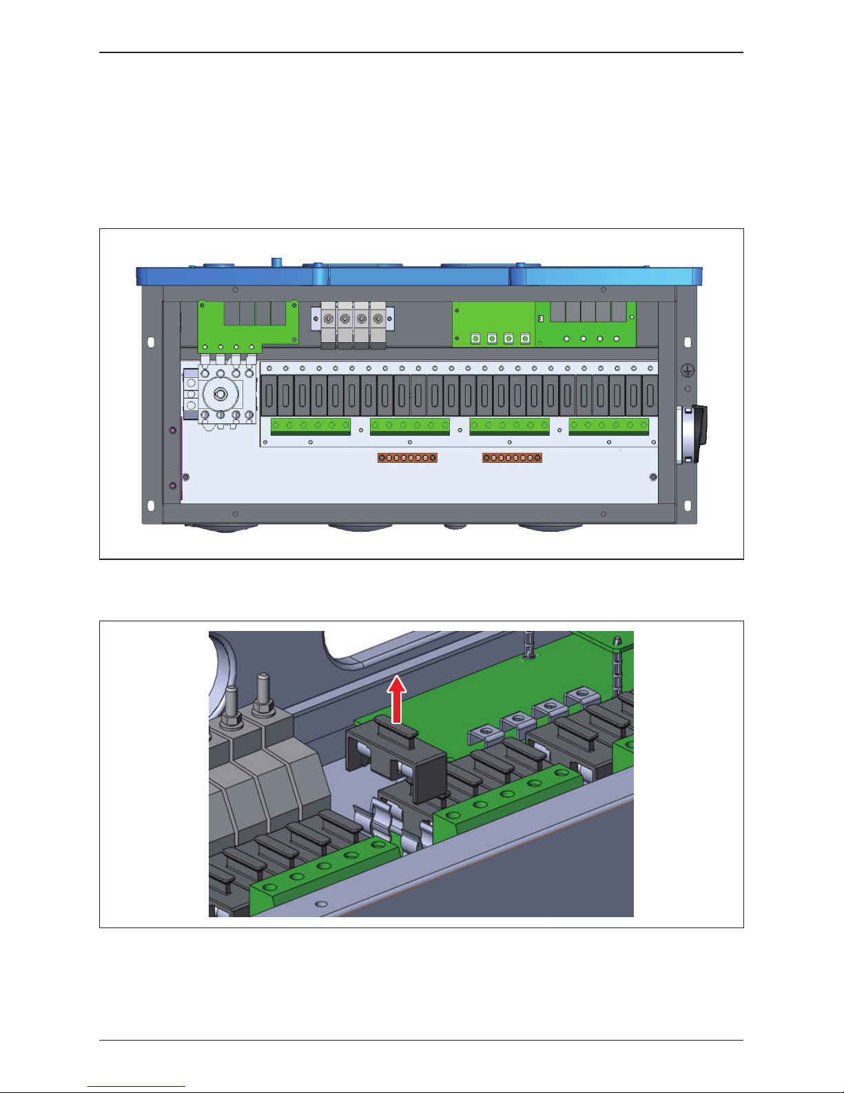
Figure 5-7: Fuse holder locations for 120/122 models
The fuse holders are mounted on two separate PWBs (one/MPPT).
The pull-out fuse holders allow safe removal of fuses which are inserted into
a carrier. Figure 5-7 shows the location of the combiner fuse holders, and
Figure 5-8 provides details to remove a fuse from the 120/122 WB; refer to
Figure 2-5 for additional information.
Figure 5-8: Accessing the individual fuses
77
Maintenance

Figure 5-9: String monitor
1 :
2 :
3 :
8.0
0.0
7.9
4 :
5 :
6 :
8.0
8.1
8.0
IDC1 (A)
1 :
2 :
3 :
8.0
8.1
7.9
4 :
5 :
6 :
8.0
0.0
8.1
IDC2 (A)
Fuse open
or blown
Fuse open
or blown
Check the combiner fuses if the power generation of inverter is abnormal using
the following procedure:
1. Check “Power meter/string monitoring” page on the LCD display, to determine
if any string current measurement is zero, which will most probably indicate
a blown fuse. (Figure 5-9)
2. Switch AC and DC power off and wait until LCD display turns off.
3. To access the wiring box, use procedure found in Section 5.1.1
4. Based on step 1, check the corresponding fuse locations by pulling out the
fuse holder (Figure 5-8) and checking continuity of the fuse.
5. Replace the fuse if necessary.
6. Re-install the WB cover, using the procedure found in Section 5.1.2
78
Maintenance
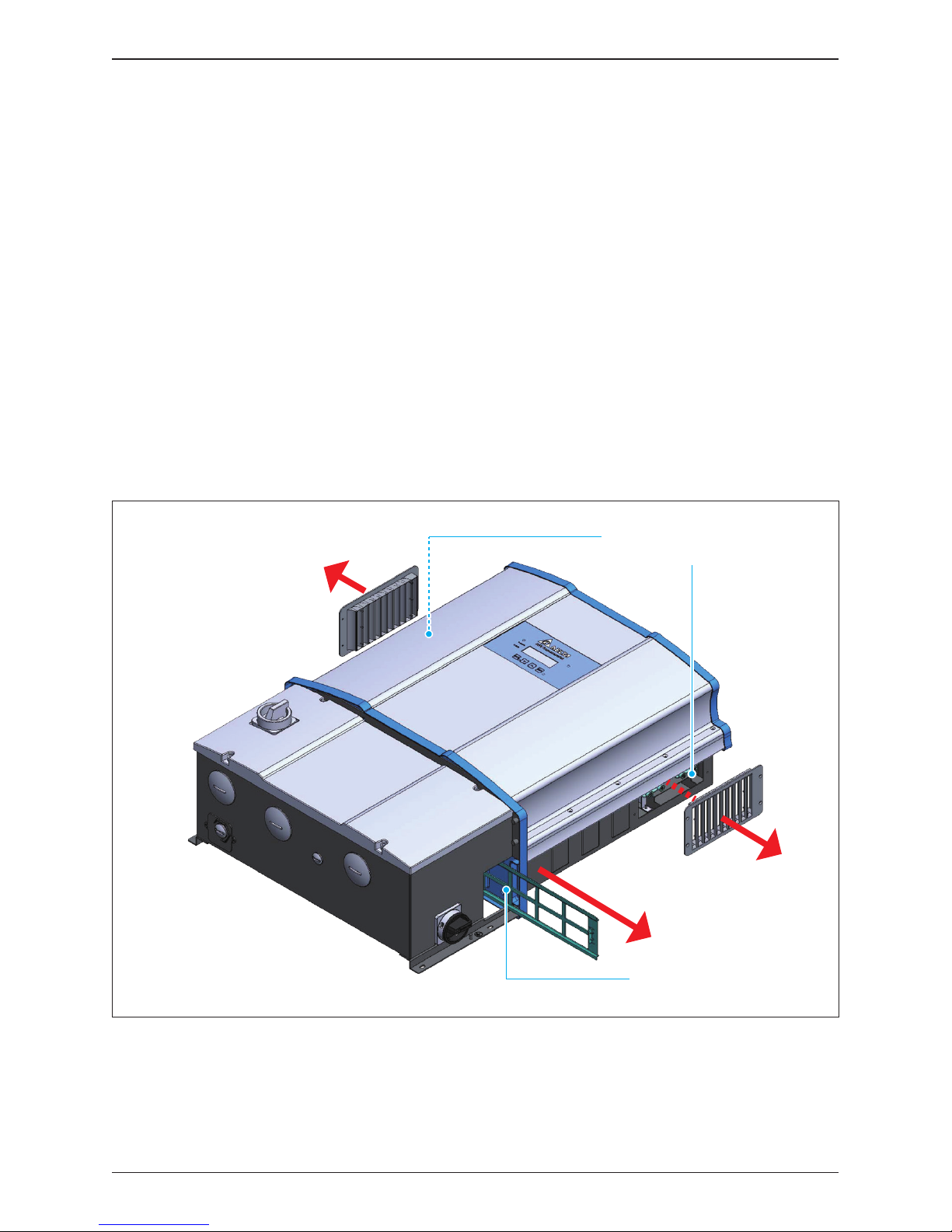
Figure 5-10: Smart Fans location on Power Module chassis
M42/36/28U models are provisioned with processor-controlled "smart fans"
for cooling of the electronics. This section provides procedures for cleaning filters
associated with these fans, and instructions for field replacement of the fans.
The fans utilized have high reliability ratings and coupled with use of processor
controls provide a "smart" cooling system design with a long life. The system
features tachometer detection of a failed fan, and generates a "FAN-FAIL"
signal that is interfaced to the inverter control to trigger a FAN-FAIL alarm and
places the inverter in a power de-rate mode as required for safe operation.
Depending upon the model, fans are installed at two locations within inverter:
• Power Module (PM) compartment (-120, -121, -122)
Figures 5-10, 5-11 illustrates the fan locations.
5.4 Smart Fans Replacement and Filter Cleaning
Air Outlets
/ Smart Fans inside PM
Air inlet duct, 2 places
79
Maintenance

Waterproof connectors
Hand grip
8 cm cooling fan with filter
8 cm cooling fan with filter
Hand grip
M42U M36/28U
or
Figure 5-11: Power Module Fan tray
Periodic fan and filter cleaning is required to insure long life and reliability.
- The time period between cleanings depends on the quality of the environment.
- Under normal duty use, Delta recommends smart fans and filters be cleaned
every 6 months
- For very dusty locations, it may be necessary to clean the fans and filters
quarterly or monthly.
ATTENTION
The cooling fans feature modular designs that make their removal for cleaning
or replacement a simple task. As a result, the replacement of fans is also smart.
80
Maintenance

Refer to Figure 5-12 and follow the steps outlined below:
1. Remove the outlet filter assemblies on the left and right side of the PM by
removing four screws on each. If filter maintenance is the goal, the two filter
elements can be cleaned at this time and reassembled.
2. On the right side, unplug the fan power wiring from their terminals.
3. On the right side, loosen the four knurled screws and remove the two screw
assemblies.
4.
Grasp the handle at the top of the fan tray and pull straight out from PM chassis.
To reassemble reverse the order of the above procedure and tighten screws to
torque values indicated in Figure 5-12.
5.4.1.1 PM Fan Tray removal procedure
The inverter electronics are convection cooled. The primary equipment used for
this function consists of a fan tray located in a plenum within the inverter power
module. The PM electronics are isolated, and heat is transferred to the plenum
airflow via a large heatsink.
The PM fan tray is modular and holds four smart fans that that operate together
and also provide redundancy; the inverter will operate to full power with two fans
operating and will enter a power derating mode under failure of a second fan.
These fans are protected by air filters at the plenum air inlet and outlet.
5.4.1 Power Module (PM) Fan Tray
81
Maintenance

Figure 5-12: Disassembling fan tray from PM chassis (showing one side only)
①
②
③
* Screw torque required for assembling:
7 lbf-in (0.8N.m)
* Screw torque required for assembling: 7 lbf-in (0.8N.m)
82
Maintenance
* Screw torque required for
assembling: 7 lbf-in (0.8N.m)

Figure 5-13: Removing the PM air inlet filter
Refer to Figure 5-13. Filter can be removed from either side of PM:
1. Unlatch the retaining hook and grasp the filter handle.
2. Carefully pull the filter frame straight out keeping it perpendicular to the side
of the PM chassis.
3. Clean the filter with warm water and allow to dry.
Reverse the above procedure to re-install the filter. When filter assembly is in
proper position, the retaining hook should be latched to the rail.
5.4.1.2 Procedures to remove PM air inlet filter
83
Maintenance

5.5 De-Commissioning
DANGER : ELECTRICAL HARZARD!!
To avoid serious injury, use follow the procedure
- Switch off internal AC switch and then both DC switches to cease inverter operation
- Switch off external AC circuit breaker or switch to disconnect the electrical grid from
the inverter chassis
- Remove array DC from chassis requires opening string level MC4 connectors in order
to break string continuity at the inverter MC4 connectors are not intended for use as a
load break switch, therefore:
Ensure inverter DC switches are open and there is no DC current flow
■ For -122 model –
Use MC4 tool to open and disconnect each string from the chassis mounted MC4
terminals at the inverter
■ For -120 model –
1. Within the connected array, open an MC4 connector within each string connected
to the inverter; repeat for strings connected to each MPPT input
2. Open WB by removing WB cover
3. For each MPPT channel,
• Use a voltmeter to check for zero voltage at the combiner output
• If any hazardous voltage level is detected, use voltmeter at the combiner input
(fuse holders) to measure voltage across each string.
• For any strings showing hazardous voltage, open external MC4 connectors in
those strings.
• Repeat measurements to insure there is no continuity in any connected string
• Loosen fuse holder screws to free string wiring and remove from wiring box
■ For -121 model –
1. For each MPPT channel
• Locate and open DC disconnect switch located at or within the associated array
combiner;
- if no switch is provisioned, open continuity of each string as described for -120
model, above
• Open inverter WB, and measure voltage across each MPPT input terminal pair
• Confirm there is no hazardous DC voltage at either input
2. Loosen fuse holder screws to free string wiring and remove from wiring box
■ RS-485 Communication module – all models
1. Remove communications module from inverter
2. Disconnect all communications wiring from the module terminals
3. Remove wiring from communications board assembly
4. Re-install communications board assembly in inverter
When necessary to remove the inverter from active operation for maintenance
or replacement, follow the instructions below.
84
Maintenance

- Use care not to touch hot surfaces if the inverter is just shutting down.
- Do not perform any task until the product cool down sufficiently.
CAUTION: HOT SURFACES, DO NOT TOUCH !
The inverter weighs more than 84 kg (185 lb).
There is risk of injury if the inverter is carried incorrectly or dropped during
transport or when attaching or removing it from the wall mounting bracket.
Personnel should wear suitable gloves to protect against injury and maintain
firm control of the inverter chassis
CAUTION: POSSIBILE INJURY !
Use care when handling mounting hardware
Do not leave loose screws and nuts inside the wiring box compartment.
ATTENTION
85
Maintenance

Table 6-1A: Error Codes and Messages
Message Possible cause Action
AC Freq
High
(E01)
1. Actual utility frequency is over
the OFR setting
2. Incorrect Grid code setting
3. Detection circuit malfunction
1. Check the utility frequency
2. Check Grid code setting
3. Contact customer service for
technical support
AC Freq
Low
(E02)
1. Actual utility frequency is under
the UFR setting
2.
Incorrect Grid code or Grid setting
3. Detection circuit malfunction
1. Check the utility frequency
2. Check Grid code & Grid setting
3. Contact customer service for
technical support
Grid Quality
(E07)
Non-linear load in Grid and near
to inverter
Grid connection of inverter need to be
far away from non-linear load if necessary
1. Wrong connection in AC terminal
2. Detection circuit malfunction
1. Check the AC connection in accordance
with the user manual
2. Contact customer service for
technical support
No Grid
(E09)
1. AC breaker is OFF
2. Disconnect in AC terminal
1. Switch on AC breaker
2. Check the connection in AC terminal and
make sure it connects to inverter
AC Volt
Low
(E10, E15,
E20)
1. Actual utility voltage is under
the UVR setting
2.
Incorrect Grid code or Grid setting
3.
Wrong connections in AC terminal
4. Detection circuit malfunction
1.
Check the utility voltage within the suitable
range
2. Check Grid code & Grid setting
3. Check the connection in AC terminal
4. Contact customer service for
technical support
AC Volt
High
(E11, E13,
E16, E18,
E21, E23)
1. Actual utility voltage is over the
OVR setting
2. Utility voltage is over the Slow
OVR setting during operation
3. Incorrect Grid code or Grid setting
4. Detection circuit malfunction
5. Wrong connection in AC terminal
1.
Check the utility voltage within the suitable
range
2. Check Grid code & Grid setting
3. Check the connection in AC terminal
4. Contact customer service for
technical support
Solar1
High
(E30)
1. MPPT 1 input voltage is over
1000Vdc
2. Detection circuit malfunction
1. Modify the solar array setting, and
make the Voc less than 1000Vdc
2. Contact customer service for
technical support
6 Error message and Trouble Shooting
While Delta Electronics endeavors to build electronic products to very high
standards of reliability, there will arise instances where the inverter may not
operate properly. When such a condition is encountered, please follow the
instructions in the Troubleshooting Guide (Tables 6-1, 6-2, and 6-3) to attempt
to clear the fault.
If fault continues to appear or if it is listed more than once in the inverter Error
log, it may be necessary to call Delta Technical Service Hot Line. A service
call checklist with necessary information for a call to the hotline is provided at
the end of the Troubleshooting guide.
Delta Technical Hotline can be reached at 1-877-440-5851 or 1-626-369-8021
6.1 Error Codes
AC Con. Fail
(E08)
86
Error message and Trouble Shooting

Table 6-1B: Error Codes and Messages
Message Possible cause Action
Solar2
High
(E31)
1. MPPT 2 input voltage is over
1000Vdc
2. Detection circuit malfunction
1. Modify the solar array setting, and
make the Voc less than 1000Vdc
2. Contact customer service for
technical support
Insulation
(E34)
1. PV array insulation fault
2. Large PV array capacitance
between Plus to Ground or
Minus to Ground or both.
3. Detection circuit malfunction
1. Check the insulation of Solar inputs
2. Check the capacitance, dry PV panel
if necessary
3. Contact customer service for
technical support
Table 6-2A: Warning Codes and Messages
Message Possible cause Action
Solar1
Low
(W01)
Solar2
Low
(W02)
AC Surge
DC Surge
1. Inverter was struck by lightning
2. One or more SPD are defective
3. One or more SPD are
disconnected
4. Detection circuit malfunction
5. Wrong connection in AC terminal
1. Check inverter’s status
2. Replace the defective SPD
3. Check the connections of SPDs
4. Check the connection in AC terminal
5. Contact customer service for
technical support
Ext Fan Fail
Int Fan Fail
(W11)
1. One or more fans are locked
2.
One or more fans are defective
3. One ore more fans are
disconnected
4. Detection circuit malfunction
1. Remove the object that stuck in the fan(s)
2. Replace the defective fan(s)
3. Check the connections of all fans
4. Contact customer service for
technical support
Ext Fan Fail
Int Fan Fail
Contact customer service for technical
support
1. MPPT 1 input voltage is under
the limit
2. Some devices were damaged
inside the inverter if the actual
MPPT 1 voltage is close to "0"
3. Detection circuit malfunction
1. Check the MPPT 1 voltage connection
to the inverter terminal
2. Check all switching devices in boost1
3. Contact customer service for
technical support
1. MPPT2 input voltage is under
the limit
2. Some devices were damaged
inside the inverter if the actual
MPPT 2 voltage is close to "0"
3. Detection circuit malfunction
1. Check the MPPT 2 input voltage
connection at the inverter terminal
2. Check all switching devices in boost2
3. Contact customer service for
technical support
6.2 Warning Codes
87
Error message and Trouble Shooting

Table 6-3A: Fault Codes & Messages
Message Possible cause Action
DC
Injection
(F01, F02,
F03)
1. Utility waveform is abnormal
2. Detection circuit malfunction
1. Check the utility waveform.
Grid connection of inverter need to be
far away from non-linear load if necessary
2. Contact customer service for
technical support
Temperature
(F05)
1. The ambient air is over 60℃
(The installation is abnormal)
2. Detection circuit malfunction
1. Check the installation ambient and
environment
2. Contact customer service for
technical support
Temperature
(F07)
1. Ambient air is less than -30℃
2. Detection circuit malfunction
1. Check the installation ambient and
environment
2. Contact customer service for
technical support
HW NTC1
Fail
(F06)
1. Ambient temperature
>90 ℃ or <-30 ℃
2. Detection circuit malfunction
1. Check the installation ambient and
environment
2. Contact customer service for
technical support
HW NTC2
Fail
(F08)
1. Ambient temperature
>90 ℃ or <-30 ℃
2. Detection circuit malfunction
1. Check the installation ambient and
environment
2. Contact customer service for
technical support
HW NTC3
Fail
(F09)
1. Ambient temperature
>90 ℃ or <-30 ℃
2. Detection circuit malfunction
1. Check the installation ambient and
environment
2. Contact customer service for
technical support
HW NTC4
Fail
(F10)
1. Ambient temperature
>90 ℃ or <-30 ℃
2. Detection circuit malfunction
1. Check the installation ambient and
environment
2. Contact customer service for
technical support
HW RLY
(F13)
1. Driver circuit for relay is
defective
2. Relay(s) is defective
3. Detection circuit malfunction
(Inverter voltage)
1. Check the input voltage, must >150Vdc
2. Replace the defective relay
3. Contact customer service for
technical support
HW DSP
ADC1
(F15)
1. Insufficient input power
2. Auxiliary power circuitry
malfunction
3. Detection circuit malfunction
1. Check the input voltage, must >150Vdc
2. Check the auxiliary circuitry inside the
inverter
3. Contact customer service for
technical support
6.3 Fault Codes
88
Error message and Trouble Shooting

Table 6-3B: Fault Codes & Messages
Message Possible cause Action
HW DSP
ADC2
(F16)
1. Insufficient input power
2. Auxiliary power circuitry
malfunction
3. Detection circuit malfunction
1. Check the input voltage, must >150Vdc
2. Check the auxiliary circuitry inside the
inverter
3. Contact customer service for
technical support
HW DSP
ADC3
(F17)
1. Insufficient input power
2. Auxiliary power circuitry
malfunction
3. Detection circuit malfunction
1. Check the input voltage, must >150Vdc
2. Check the auxiliary circuitry inside the
inverter
3. Contact customer service for
technical support
1. Insufficient input power
2. Auxiliary power circuitry
malfunction
3. Detection circuit malfunction
1. Check the input voltage, must >150Vdc
2. Check the auxiliary circuitry inside the
inverter
3. Contact customer service for
technical support
1. Insufficient input power
2. Auxiliary power circuitry
malfunction
3. Detection circuit malfunction
1. Check the input voltage, must >150Vdc
2. Check the auxiliary circuitry inside the
inverter
3. Contact customer service for
technical support
HW Red
ADC1
(F18)
HW Red
ADC2
(F19)
HW Eff.
(F20)
1. The calibration is incorrect
2. Current feedback circuit is
defective
1. Check the accuracy of current and power
2. Check the current feedback circuit
inside the inverter
HW
COMM1
(F23)
1. DSP is idling
2. The communication
connection is disconnected
3. The communication circuit
is malfunction
1. Contact customer service for
technical support
2. Check the connection interface RS-485
3. Check the communication card
HW
COMM2
(F22)
1. Red. CPU is idling
2. The internal communication
connection is disconnected
Contact customer service for technical
support
Ground Cur.
(F24)
1. PV array insulation fault
2. Large PV array capacitance
between Plus to Ground or
Minus to Ground
3. Either side of boost driver
or boost choke malfunction
4. Detection circuit malfunction
1. Check the insulation of Solar inputs
2. Check the capacitance (+ <-> GND &
- <-> GND), must < 2.5uF. Install
external transformer if necessary
3. Contact customer service for
technical support
89
Error message and Trouble Shooting

Table 6-3C: Fault Codes & Messages
Message Possible cause Action
HW Con. Fail
(F26)
1. Power line is disconnected
inside the inverter
2. Current feedback circuit is
defective
1. Check the power lines inside the inverter
2. Contact customer service for
technical support
RCMU Fail
(F27)
1. RCMU is disconnected
2. Detection circuit malfunction
1. Check the RCMU connection inside the
inverter
2. Contact customer service for
technical support
1. One or more relays are
sticking
2. The driver circuit for the
relay malfunction
3. Wrong connection in AC
terminal
1. Check the connection in AC terminal
2. Contact customer service for
technical support
1. One or more relays are
abnormal
2. The driver circuit for the
relay malfunction
3. The detection accuracy is
not correct for Vgrid and Vout
Contact customer service for technical
support
RLY Short
(F28)
RLY Open
(F29)
Bus Unbal.
(F30)
1. Not totally independent or
parallel between inputs
2. PV Array short to Ground
3. Driver for boost is defective
or disconnected
4. Detection circuit malfunction
1. Check the inputs connections
2. Check the PV Array insulation
3. Contact customer service for
technical support
HW Bus OVR
(F31, F33, F35)
1. Driver for boost is defective
2. Voc of PV array is over
1000Vdc
3. Surge occurs during
operation
4. Detection circuit malfunction
Contact customer service for technical
support
AC Cur. High
(F36, F37, F38,
F39, F40, F41)
1. Surge occurs during
operation
2. Driver for inverter stage is
defective
3. Switching device is defective
4. Detection circuit malfunction
Contact customer service for technical
support
Contact customer service for technical
support
HW CT A Fail
(F42)
1. Test current loop is broken
2. CTP3 is defective
3. Detection circuit malfunction
90
Error message and Trouble Shooting

Table 6-3D: Fault Codes & Messages
Message Possible cause Action
HW CT B Fail
(F43)
1. Test current loop is broken
2. CTP4 is defective
3. Detection circuit malfunction
HW CT C Fail
(F44)
1. Test current loop is broken
2. CTP5 is defective
3. Detection circuit malfunction
1. Large Grid harmonics
2. Switching device is defective
3. Detection circuit malfunction
1. Check the utility waveform. Grid connection
of inverter needs to be far away from
non-linear load if necessary
2. Check all switching devices in inverter
stage
3. Contact our customer service for
technical support
1. AFCI is not installed.
2. AFCI self-test is fail.
Check the AFCI detection circuit board to
insure proper connections
Contact customer service for technical
support
HW AC OCR
(F45)
AFCI Circuit
Fail
(F58)
One or more DC relays are
abnormal
Contact customer service for technical
support
HW DC RLY
(F76)
The inverter detects Arcing
occurs.
Check PV array cables for replacement
AFCI Fault
(F59)
DC Cur. High
(F60, F61,
F70, F71)
1. Switching device in boost
is defective
2. Driver for boost is defective
3. Input current detection
circuit malfunction
1. Check all switching device in boost
2. Check the driver circuit for boost inside
the inverter
3. Check input current detection circuit
Contact customer service for technical
support
Contact customer service for technical
support
91
Error message and Trouble Shooting

In order for Delta Hotline personnel to efficiently handle your service request, certain
information must be made availble to the service technician.
Prior to calling the Delta Service Hotline, the information listed below must be assembled:
6.4.1 Service Call Checklist
6.4 Calling for Help
1. Installation Information
a. Location of the install
b. How many inverters
c. Date of Commissioning (if known)
2. Check the Product Label or use LCD display to view and record:
a. Model number
b. Serial number
c. Production date
3. State of the LCD:
a. Is the display active (powered)?
b. What is the state of the inverter?
c. What is the error message or code?
d. Can the Error Log be accessed?
i.
If, so, please list code number, date and time for any log entry in 24 hr period prior
to appearance of error code on LCD screen
4. Status of LED warning lights.
a. What LED color(s) are lighted, if any?
b. Are the LEDs flashing on and off, or lighted continuously?
5. System configuration:
a. What is brand and model of photovoltaic modules?
b. What is number of PV modules per string
c. Number of strings in each array
d. What is maximum array voltage and current values
6. System condition:
a. Can the fault or error be reproduced? If so, how?
b. Is the fault cyclical in nature? If so, how often?
c. Was the fault apparent at the time of installation? If so, has it worsened?
d.
Describe the atmospheric conditions at the time the fault/error appears or appeared.
Delta Technical Hotline can be reached at 1-877-440-5851 or 1-626-369-8021.
92
Error message and Trouble Shooting
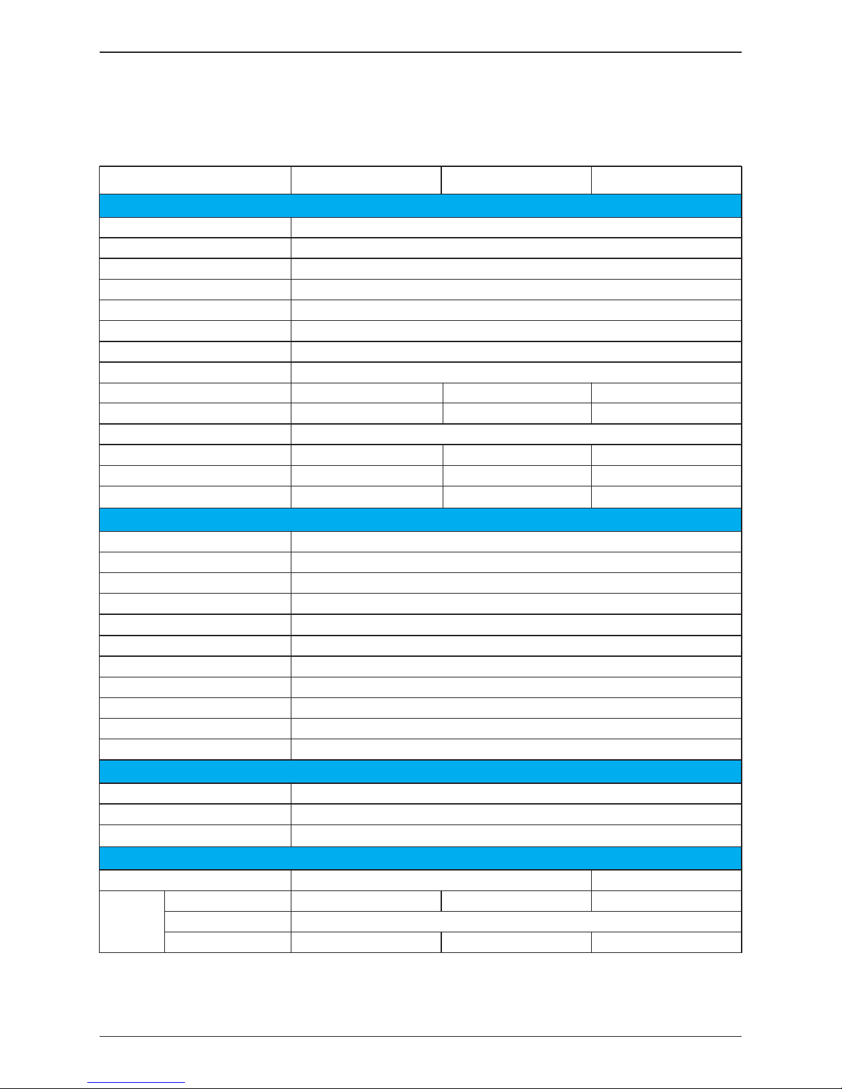
7 Technical Data
7.1 Technical of M42U series
Maximum input voltage
Operating voltage range
Start voltage
V
MPP range for POUT-RATED
Connection type
Combiner fuses
Surge protection, DC side
DC disconnect switch
Number of MPP trackers
Current limit, I
MP-MAX /MPPT
M42U
_120 M42U_121 M42U_122
1100V* (1000V MAX for NEC)
200 - 1000 V
>250 V
545 - 830 V
40A/MPPT
Allowable array ISC-MAX /MPPT
100A/MPPT
String current monitor
Allowable conductors
Rated voltage 710 V
2
Rated output power
Max. output power
Allowable grid configuration
Line frequency range
THD
Connection type
Surge protection, AC side
Night time consumption
42kW
46kW
Rated line voltage
3Ø-4W-Yg or 3Ø-3W
4W: 480/277±10% ; 3W: 480V±10%
Max. output current 56.2A
Efficiency
Peak efficiency
CEC efficiency
98.6 %
98.0 %
50/60Hz
<3%
<3W
Power factor Unity at P
RATED; adjustable: [0.8 ind ~0.8 cap]
AC Switch & Terminal block #4~#6 AWG
Euro efficiency 98.4 %
SPD Type II 10kA (8 x20us)
Dimensions (W x H x D) [in]
* The max withstand voltage is 1100Vdc. (inverter ceases operation if input exceeds 1000Vdc)
W/O Wiring box
Weight
[lb]
Shipping weight
24.2 x 32.2 x 10.8 24.2 x 34 x 10.8
W/ Wiring box 132.9 127.6 132.5
150.9 145.6 150.5
99.2
12 pr. Fuse holders 2pr. Terminal blocks 12 pr. MC4 connectors
#10~#12 AWG, Cu only
#2~#8 AWG, Cu/Al
SPD Type II 10kA (8 x20us)
#10~#12 AWG, Cu only
24 x 15A Not Provisioned 24 x 15A
Yes Yes Yes
Yes Not Provisioned Yes
DC Input
AC Output
General Data
93
Technical Data
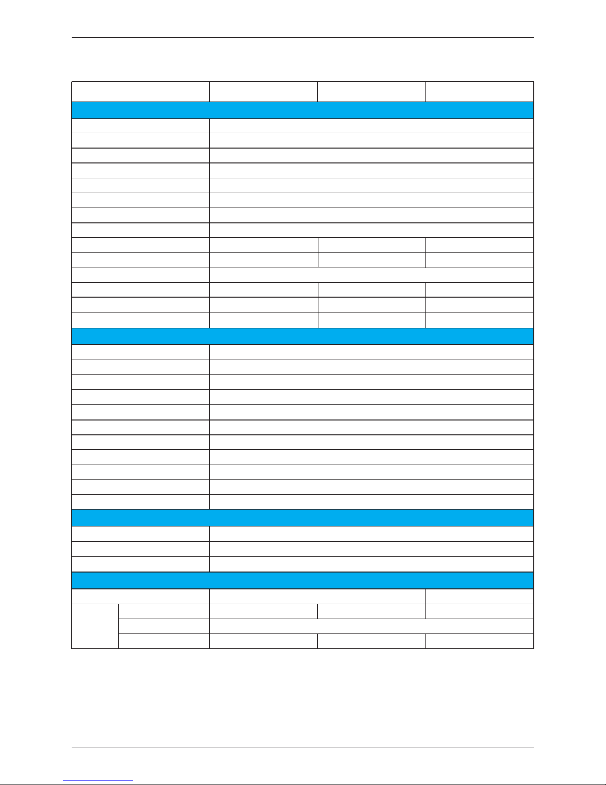
7.2 Technical of M36U series
Maximum input voltage
Operating voltage range
Start voltage
V
MPP range for POUT-RATED
Connection type
Combiner fuses
Surge protection, DC side
DC disconnect switch
Number of MPP trackers
Current limit, I
MP-MAX /MPPT
M36U
_120 M36U_121 M36U_122
1100V* (1000V MAX for NEC)
200 - 1000 V
>250 V
520 - 830 V
36A/MPPT
Allowable array ISC-MAX /MPPT
100A/MPPT
String current monitor
Allowable conductors
Rated voltage 710 V
2
Rated output power
Max. output power
Allowable grid configuration
Line frequency range
THD
Connection type
Surge protection, AC side
Night time consumption
36kW
39.6kW
Rated line voltage
3Ø-4W-Yg or 3Ø-3W
4W: 480/277±10% ; 3W: 480V±10%
Max. output current 48.2A
Efficiency
Peak efficiency
CEC efficiency
98.6 %
98.0 %
50/60Hz
<3%
<3W
Power factor Unity at P
RATED; adjustable: [0.8 ind ~0.8 cap]
AC Switch & Terminal block #4~#6 AWG
Euro efficiency 98.4 %
SPD Type II 10kA (8 x20us)
Dimensions (W x H x D) [in]
* The max withstand voltage is 1100Vdc. (inverter ceases operation if input exceeds 1000Vdc)
W/O Wiring box
Weight
[lb]
Shipping weight
24.2 x 32.2 x 10.8 24.2 x 34 x 10.8
W/ Wiring box 129 123.7 128.5
147 141.7 146.5
99.2
10 pr. Fuse holders 2pr. Terminal blocks 10 pr. MC4 connectors
#10~#12 AWG, Cu only
#2~#8 AWG, Cu/Al
SPD Type II 10kA (8 x20us)
#10~#12 AWG, Cu only
20 x 15A Not Provisioned 20 x 15A
Yes Yes Yes
Yes Not Provisioned Yes
DC Input
AC Output
General Data
94
Technical Data

7.3 Technical of M28U series
Maximum input voltage
Operating voltage range
Start voltage
V
MPP range for POUT-RATED
Connection type
Combiner fuses
Surge protection, DC side
DC disconnect switch
Number of MPP trackers
Current limit, I
MP-MAX /MPPT
M28U
_120 M28U_121 M28U_122
1100V* (1000V MAX for NEC)
200 - 1000 V
>250 V
485 - 830 V
30A/MPPT
Allowable array ISC-MAX /MPPT
50A/MPPT
String current monitor
Allowable conductors
Rated voltage 710 V
2
Rated output power
Max. output power
Allowable grid configuration
Line frequency range
THD
Connection type
Surge protection, AC side
Night time consumption
28kW
30.8kW
Rated line voltage
3Ø-4W-Yg or 3Ø-3W
4W: 480/277±10% ; 3W: 480V±10%
Max. output current 37.5A
Efficiency
Peak efficiency
CEC efficiency
98.6 %
98.0 %
50/60Hz
<3%
<3W
Power factor Unity at P
RATED; adjustable: [0.8 ind ~0.8 cap]
AC Switch & Terminal block #4~#6 AWG
Euro efficiency 98.4 %
SPD Type II 10kA (8 x20us)
Dimensions (W x H x D) [in]
* The max withstand voltage is 1100Vdc. (inverter ceases operation if input exceeds 1000Vdc)
W/O Wiring box
Weight
[lb]
Shipping weight
24.2 x 32.2 x 10.8 24.2 x 34 x 10.8
W/ Wiring box 122.6 117.3 122.1
140.6 135.3 140.1
99.2
8 pr. Fuse holders 2pr. Terminal blocks 8 pr. MC4 connectors
#10~#12 AWG, Cu only
#2~#8 AWG, Cu/Al
SPD Type II 10kA (8 x20us)
#10~#12 AWG, Cu only
16 x 15A Not Provisioned 16 x 15A
Yes Yes Yes
Yes Not Provisioned Yes
DC Input
AC Output
General Data
Technical Data
95

7.5 Certifications
7.4 Communications
Operating TAMB range
Operating elevation
Environment protection
Cooling method
-13°~140°F (-25°~60°C)
Comm port | Protocol
Display
RS-485 | Delta or Sunspec
20 x4 line LCD
Safety
Interconnection
UL1741 SA UL1741, UL1998, UL1699B, CSA C22.2, FCC Pt.15 (Class B)
IEEE1547, IEEE 1547.1
<9800 ft (3000m)
NEMA 4X
Forced air cooling with Smart Fan controls
General Data
7.7 General Data
Communications
Certifications
7.6 Smart Inverter Functionality
Smart Inverter Designations
Adjustable Controls
Utility Support Grid Interactive Inverter (UL1741 SA)
CEC Approved CA Rule 21 compatible
V, F Ride-through, PF adjust, Ramp rate control
Autonomous Functions
Volt/VAR, Volt/Watt, Active power curtailment
Smart Inverter Functionality
96
Technical Data

Figure 7-1: Thermal Derating curve of M42U
30
25
35
40 45 50
55
60
50 %
55 %
60 %
65 %
70 %
75 %
80 %
85 %
90 %
95 %
100 %
105 %
110 %
115 %
P/P*
P*=42kW
545V
710V
830V
Temperature Derating of M42U
97
Technical Data

Figure 7-2: Thermal Derating curve of M36U
30
25
35
40 45 50
55
60
50 %
55 %
60 %
65 %
70 %
75 %
80 %
85 %
90 %
95 %
100 %
105 %
110 %
115 %
P/P*
P*=36kW
520V
710V
830V
Temperature Derating of M36U
98
Technical Data

Figure 7-3: Thermal Derating curve of M28U
30
25
35
40 45 50
55
60
50 %
55 %
60 %
65 %
70 %
75 %
80 %
85 %
90 %
95 %
100 %
105 %
110 %
115 %
P/P*
P*=28kW
485V
710V
830V
Temperature Derating of M28U
99
Technical Data
Region
High Voltage 2 (HV2)
High Voltage 1 (HV1)
Near Nominal (NN)
Low Voltage 1 (LV1)
Low Voltage 2 (LV2)
Low Voltage 3 (LV3)
a
While these operating parameters correspond to the Rule 21 parameters, they may be substituted with
operating parameters for other area EPS requirements.
Note 1: Manufacturer may evaluate product over wider ranges of adjustment than those within the table.
Note 2: The table voltage could be either at the PCC or equipment terminals.
Note 3: For LV3 or HV1 the EUT shall cease to energize in not more than 0.16s (and not trip).
This may differ in other SRD(s).
Appendix A-1: Low and High Voltage Ride-Through Set-points and Timing per Table SA9.1
Default operating parameters that correspond to Rule 21 L/HVRT
a
Appendix A-2: Low and High Frequency Ride-Through Set-points and Timing per Table SA10.1
Default operating parameters that correspond to Rule 21 L/HFRT
a
V ≥ 120
110 < V < 120
88 ≤ V ≤ 110
70 ≤ V < 88
50 ≤ V < 70
V < 50
Not Applicable
12s
Indefinite
20s
10s
1s
Not Applicable
Momentary Cessation
Continuous Operation
Mandatory Operation
Mandatory Operation
Momentary Cessation
0.16s
13s
Not Applicable
21s
11s
1.5s
Voltage
(% Nominal Voltage)
Ride-Through Until Operating Mode
Maximum Trip Time
(s)
APPENDIX: Grid Support Utility Interactive Inverters
Appendix A: CA Rule 21
The inverter has pre-programmed control presets intended for use in specific geographic
areas. They include:
• Rule 21 – Preset all required controls to meet the F/VRT specifications that satisfy
CA Power Tariff Rule 21
• HECO A – Presets all required controls to meet the for the Hawaiian Islands of O’ahu,
Hawai’i Island, and Maui
• HECO B – Presets all required controls to meet the F/VRT specifications for the
Hawaiian Islands of Moloka’i and Lana’i
The following sections provide details of the settings and its adjustable range.
Region
High Frequency 2 (HF2)
High Frequency 1 (HF1)
Near Nominal (NN)
Low Frequency 1 (LF1)
Low Frequency 2 (LF2)
a
While these operating parameters correspond to the Rule 21, 2015 parameters, they may be substituted
with operating parameters for other area EPS requirements.
Note 1: Manufacturer may evaluate product over wider ranges of adjustment than those within the table.
Note 2: Frequency / Watt functionality is an option under the Rule 21, 2015 filing.
f > 62
60.5 < f ≤ 62
58.5 < f ≤ 60.5
57.0 < f ≤ 58.5
f ≤ 57.0
62.0 - 64.0
60.1 - 62.0
Not Applicable
57.0 - 59.9
53.0 - 57.0
Not Applicable
Momentary Cessation
Continuous Operation
Not Applicable
System Frequency
Default Settings
Minimum Range of
Adjustability (Hz)
Ride-Through
Until (s)
Ride-Through
Operational Mode
0.16
300
Not Applicable
300
0.16
Trip Time (s)
Mandatory Operation
Mandatory Operation
Mandatory
Operation
Continuous
Operation
Mandatory
Operation
Not Applicable
100
Appendix A: Rule 21
 Loading...