

Page 1
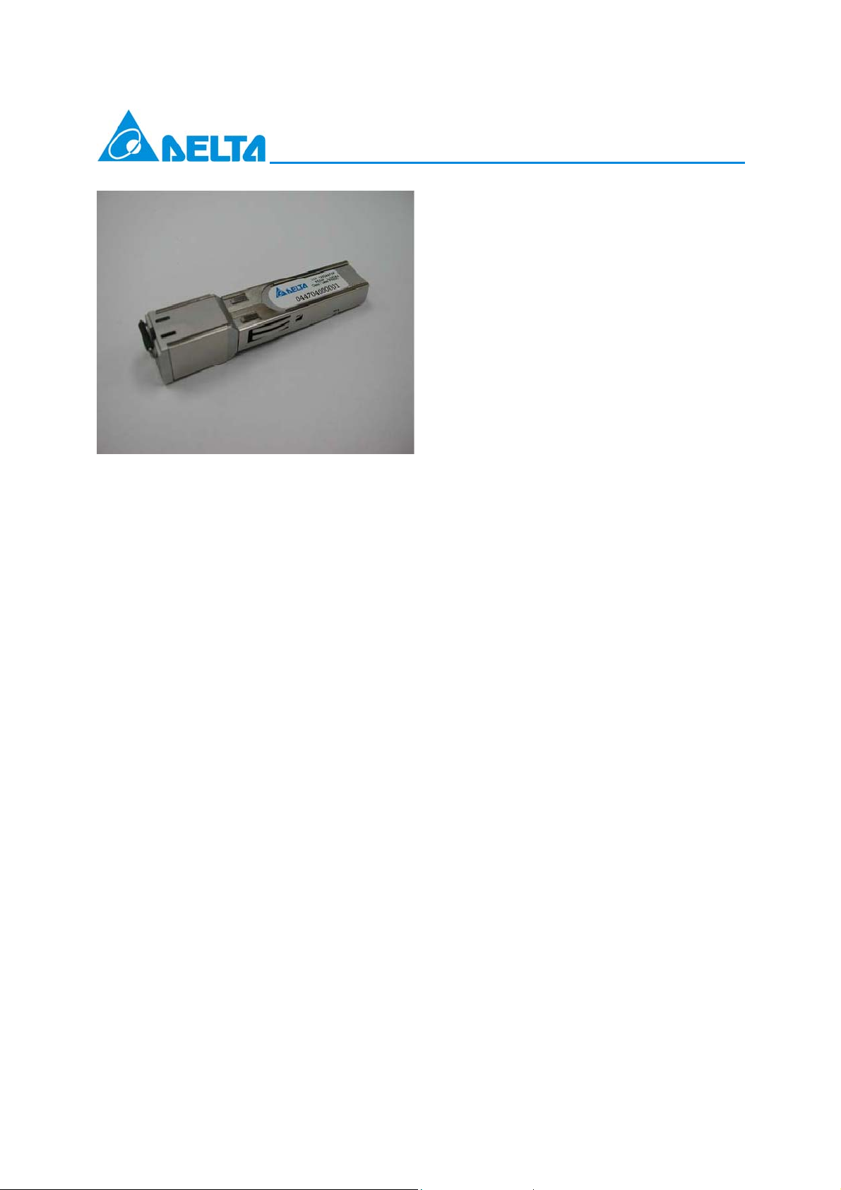
LCP-1250RJ3SR-S
Features
Compliant with specifications for IEEE
802.3z/Gigabit Ethernet
Compliant with MSA specifications for Small
Form Factor Pluggable (SFP)Ports
Hot-pluggable SFP footprint
10/100/1000 BASE-T operation in the host
system with SGMII interface (Default)
1000 BASE-T operation in the host system with
SerDes interface (To be configured)
Compliant with industry standard RFT electrical
connector and cage
EEPROM with serial ID functionality
Description
The LCP-1250RJ3SR-S is a 3.3V copper
small form-factor pluggable (SFP) transceiver.
It offers full duplex 1000M/s Ethernet by
transporting data over standard CAT 5 UTP
cable(category 5 unshielded twisted pair, with
R J-45 connection. It takes signals from both
CAT 5 UTP cable and the SFP SerDes
interface.
The system host (MAC)must enable
SGMII auto-negotiation while
LCP-1250RJ3SR-S is oper ated to setup the
partner linking at one speed of 10/100/1000
Mbps by 1000Base-T auto-negot iation.
The Gigabit Ethernet SFP ports on host
systems can work well plugging with both of
Delta fiber SFP transceiver and Delta copper
SFP transceiver, so there is no need of
software to configure MAC on host system.
At enhance, the software can configure the PHY
device inner LCP-1250RJ3SR-S via SFP
two-wire-interface. The SGMII interface without
clock is selected by setting HWCFG_MODE[3:0]
bits to ‘1100’ or ‘1000’.
Auto-Negotiation follows IEEE 802.3u Clause
28 (1000BASE-T) and Cisco SGMII Spec.
Compatible with the Cisco specification of
SGMII interface.LCP-1250RJ3SR-S supports
the SGMII interface without clock on MAC side.
Gigabit PHY device is integrated internally
Internal PHY IC is configurable by host system
software via SFP 2-wire-interface.
Applications
Gigabit Ethernet over copper
Switch to Switch interface
Switched backplane applications
File server interface
Performance
LCP-1250RJ3SR-S data link up to 100m on
standard CAT 5 UTP
DELTA ELECTRONICS, INC.
1
Oct. 17. 2007 Rev. 1.02
www.deltaww.com
Page 2
Product Selection
y
LCP-1250RJ3SR-S
Part Number
Link Indictor On RX_LOS
Pin
Auto-negotiation on MAC
side Enabled by default
MAC side Interface
Auto-negotiation on
copper side Enabled b
default
Speed Mode (default)
LCP-1250RJ3SR
*note1
N/A Available N/A
1000Base-X Yes SGMII
1.25Gbps SerDes 1.25Gbps SerDes SGMII without clock
1000Base-T 1000Base-T 1000Base-T
1000Mbps only 1000Mbps only 10/100/1000Mbps
LCP-1250RJ3SR-L
*note2
LCP-1250RJ3SR-S
*note3
Notes:
1. This part supports the 1000 Base-T with SerDes interface by default. It can operate in 10/100/1000
Base-T with SGMII interface by reconfiguration of the PHY within the SFP.
2. This part uses the SFP’s Rx-Los pin for link indication and 1000 Base-T auto-negotiation should be
disabling on the host system. It can operate in 10/100/1000 Base-T with SGMII interface by
reconfiguration of the PHY within the SFP.
3. This part supports the 10/100/1000 Base-T with SGMII interface by default. It can operate in 1000
Base-T with SerDes interface by reconfiguration of the PHY within the SFP.
Serial Interface Configuration (PHY Two-Wire Address 0xAC)
Register Bits Field Mode Description
27 3:0 HWCFG_
MODE
R/W Changes to these bits are disruptive to the normal
operation; hence, any changes to these registers must be
followed by software reset to take effect.
Upon hardware reset Register 27.3:0 defaults to the value
in HWCFG_MODE[3:0].
0100 = SGMII without Clock with SGMII Auto-Neg to
copper
1000 = 1000BASE-X without Clock with 1000BASE-X
Auto-Neg to copper (GBIC)
1100 = 1000BASE-X without Clock without 1000BASEX
Auto-Neg to copper
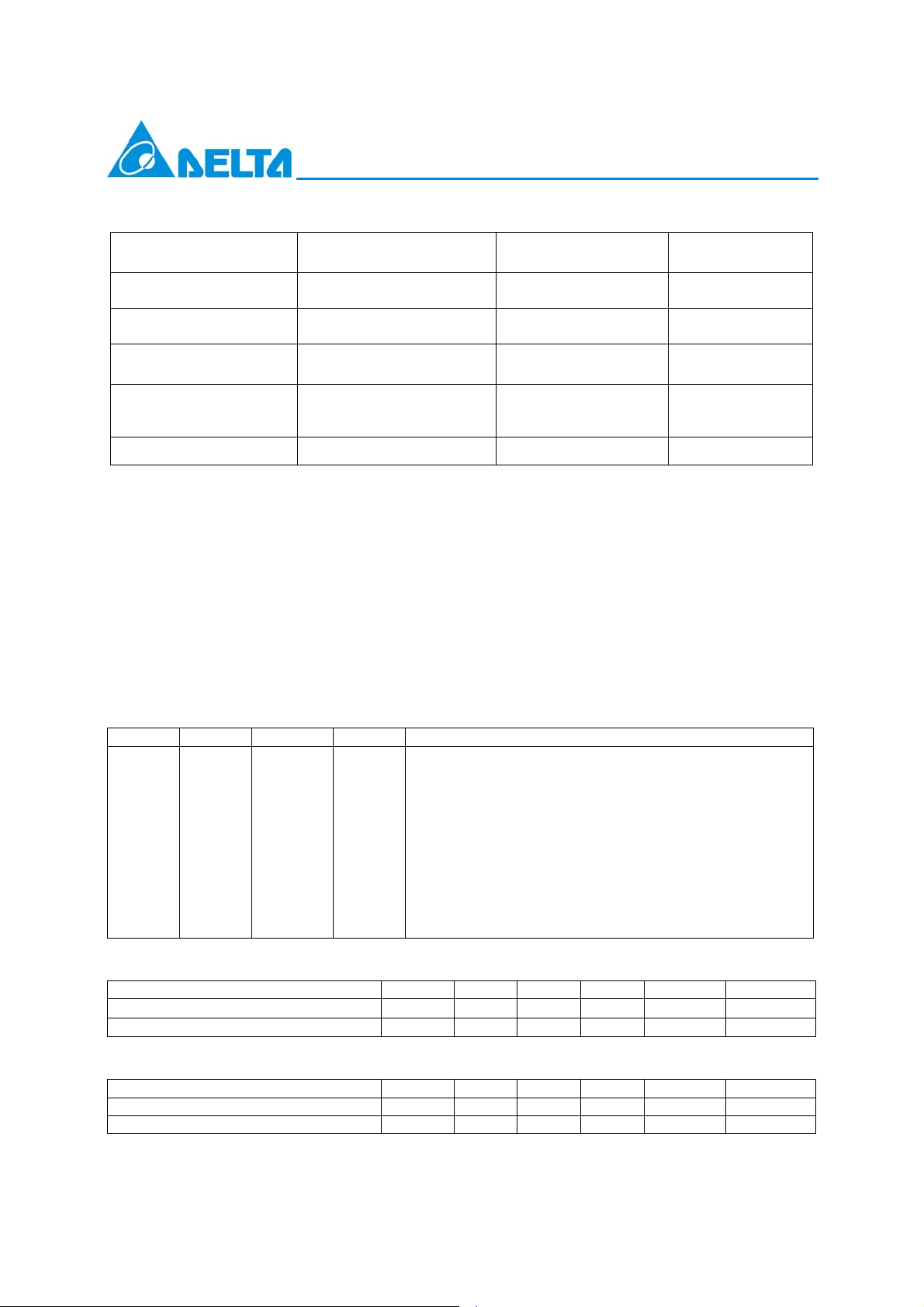
Absolute Maximum Ratings
Parameter Symbol Min. Typ. Max. Unit Note
Storage Temperature Ts
Supply Voltage VCC 0 5 V
−
40
85 ºC
Recommended Operating Conditions
Parameter Symbol Min. Typ. Max. Unit Note
Ambient Operating Temperature TA 0 70 ºC
Supply Voltage VCC 3.135 3.465 V
2
Oct. 17. 2007 Rev. 1.02
DELTA ELECTRONICS, INC.
www.deltaww.com
Page 3
Electrical Characteristics
(TA=0 ºC to 70 ºC, VCC=3.135V to 3.465V)
Parameter Symbol Min. Typ. Max. Unit Note
Supply Current ICC 350 400 mA
Transmitter
Transmitter Differential Input Voltage V
Differential Input Impedance ZTX 80 100 120 Ohm
Transmitter Disable Input-High V
Transmitter Disable Input-Low V
Receiver
Data Output Differential Voltage V
Differential Output Impedance ZRX 80 100 120 Ohm
Data Output Rise/Fall Time t
Notes:
1. Internally AC coupled and terminated to 100-Ohm differential load.
LCP-1250RJ3SR-S
0.5 2.4 V 1
D,TX
2.0 VCC+0.3 V
DISH
0 0.8 V
DISL
0.35 2 V 3
D,RX
r,Rx
/ t
f,Rx
180 ps 4
2. Pull up to V
with a 4.7K – 10K Ohm resistor on host Board
CC
3. Internally AC coupled, but requires a 100-Ohm differential termination at MAC side.
4. These are unfiltered 20%~80% values
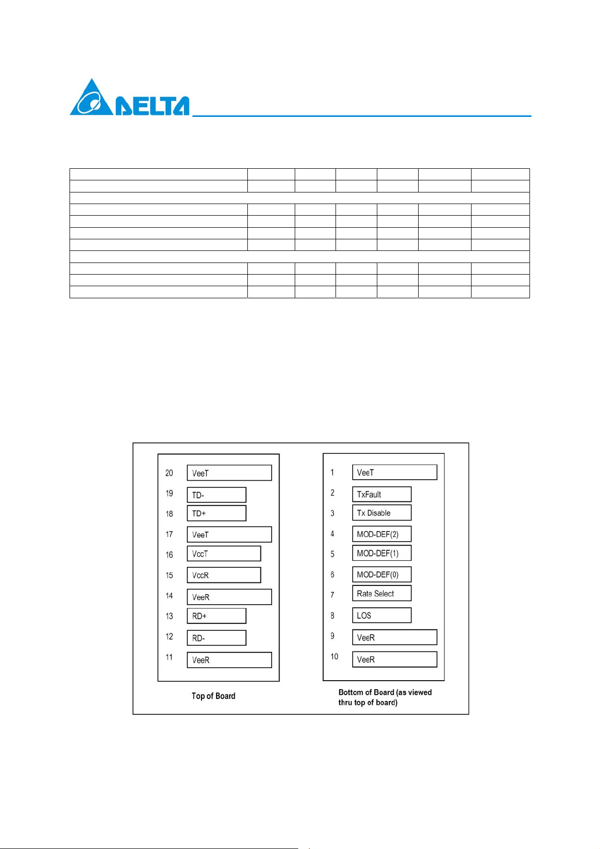
SFP Transceiver Electrical Pad Layout
DELTA ELECTRONICS, INC.
3
Oct. 17. 2007 Rev. 1.02
www.deltaww.com
Page 4

Pin Function Definitions
Pin Num. Name Function Plug Seq. Notes
1 VeeT Transmitter Ground 1 Note 5
2 TX Fault Transmitter Fault Indication 3 Note 1 - Function not available
3 TX Disable Transmitter Disable 3
4 MOD-DEF2 Module Definition 2 3 Note 3 - Two-wire serial ID interface
5 MOD-DEF1 Module Definition 1 3 Note 3 - Two-wire serial ID interface
6 MOD-DEF0 Module Definition 0 3 Note 3 - grounded in module
7 Rate Select Not Connect 3 Function not available
8 LOS Loss of Signal 3 Note 4 - Function not available
9 VeeR Receiver Ground 1 Note 5
10 VeeR Receiver Ground 1 Note 5
11 VeeR Receiver Ground 1 Note 5
12 RD- Inverse Received Data Out 3 Note 6
13 RD+ Received Data Out 3 Note 6
14 VeeR Receiver Ground 1 Note 5
15 VccR Receiver Power 2 Note 7 - 3.3V ± 5%
16 VccT Transmitter Power 2 Note 7 - 3.3V ± 5%
17 VeeT Transmitter Ground 1 Note 5
18 TD+ Transmitter Data In 3 Note 8
19 TD- Inverse Transmitter Data In 3 Note 8
20 VeeT Transmitter Ground 1 Note 5
Plug Seq.: Pin engagement sequence during hot plugging.
LCP-1250RJ3SR-S
Note 2 - Module disables on high or
open
DELTA ELECTRONICS, INC.
4
Oct. 17. 2007 Rev. 1.02
www.deltaww.com
Page 5

Notes:
1) TX Fault is not supported and tied to ground.
2) TX disable is an input that is used to reset the chip of Gigabit Ethernet PHY inside the copper SFP. It is pulled
up within the module with a 4.7 – 10 K resistor.
Low (0 – 0.8V): Transmitter on
(>0.8, < 2.0V): Undefined
High (2.0 – 3.465V): Transmitter Disabled
Open: Transmitter Disabled
3) These are the module definition pins. They should be pulled up with a 4.7K – 10K resistor on the host board.
The pull-up voltage shall be VccT or VccR. MOD-DEF 0 is grounded in the module to indicate that the module is
present. MOD-DEF 1 and MOD-DEF 2 are the clock and data lines of the two-wire serial interface, respectively.
4) LOS (Loss of Signal) is not supported and tied to ground.
5) VeeR and VeeT are internally connected within the copper SFP.
6) RD+ and RD- are the received differential outputs, and they are AC-coupled 100 differential lines that should be
terminated with 100 (differential) at user’s SERDES. The AC coupling is done inside the copper SFP and thus
not required on the host board. The differential voltage swing will be between 250mV and 625 mV, while properly
terminated.
LCP-1250RJ3SR-S
7) VccR and VccT are the receiver and transmitter power supplies, and they are internally connected within the
copper SFP. The power rail is defined as 3.3V ±5% at the SFP connector pin.
8) TD+ and TD- are the transmitted differential inputs, and they are terminated with 100 differential load
inside the module. The AC coupling is done inside the module, and thus not required on the host
board.
DELTA ELECTRONICS, INC.
5
Oct. 17. 2007 Rev. 1.02
www.deltaww.com
Page 6

Recommend Circuit Schematic
LCP-1250RJ3SR-S
6
Oct. 17. 2007 Rev. 1.02
DELTA ELECTRONICS, INC.
www.deltaww.com
Page 7

LCP-1250RJ3SR-S
Package Outline Drawing for Metal Housing
DELTA ELECTRONICS, INC.
7
Oct. 17. 2007 Rev. 1.02
www.deltaww.com
Page 8

LCP-1250RJ3SR-S EEPROM Serial ID Memory Contents (Two-Wire Address A0h)
Address
Hex ASCII
00 03 25 20 50 33 3 75 SN 100 00 125 00
01 04 26 20 51 53 S 76 SN 101 00 126 00
02 00 27 20 52 52 R 77 SN 102 00 127 00
03 00 28 20 53 2D - 78 SN 103 00
04 00 29 20 54 53 S 79 SN 104 00
05 00 30 20 55 20 80 SN 105 00
06 08 31 20 56 30 0 81 SN 106 00
07 00 32 20 57 30 0 82 SN 107 00
08 00 33 20 58 30 0 83 SN 108 00
09 00 34 20 59 30 0 84 DC Note 3 109 00
10 00 35 20 60 00 85 DC 110 00
11 01 36 00 61 00 86 DC 111 00
12 0D 37 00 62 00 87 DC 112 00
13 00 38 00 63 CS1 Note 1 88 DC 113 00
14 00 39 00 64 00 89 DC 114 00
15 00 40 4C L 65 01 90 DC 115 00
16 00 41 43 C 66 00 91 DC 116 00
17 00 42 50 P 67 00 92 00 117 00
18 64 43 2D - 68 SN Note 2 93 00 118 00
19 00 44 31 1 69 SN 94 00 119 00
20 44 D 45 32 2 70 SN 95 CS2 Note 4 120 00
21 45 E 46 35 5 71 SN 96 00 121 00
22 4C L 47 30 0 72 SN 97 00 122 00
23 54 T 48 52 R 73 SN 98 00 123 00
24 41 A 49 4A J 74 SN 99 00 124 00
Notes:
1) Byte 63(CS1): Check sum of bytes 0-62.
Address
Hex ASCII
Address
LCP-1250RJ3SR-S
Hex ASCII
Address
Hex ASCII
Address
Hex ASCII
Address
Hex ASCII
2) Byte 68-83 (SN): Serial number.
3) Byte 84-91 (DC): Date code.
Byte 95 (CS2): Check sum of bytes 64-94.
4)
5) Byte 128-255 had been set hex.00.
LCP-1250RJ3SR-S Internal PHY Register (Two-Wire Address 0xAC)
LCP-1250RJ3SR-S is internally designed of physical layer IC (Marvell 88E1111), which can be programmed
via two-wire interface with the device address 0xAC. For details of PHY IC registers in 88E1111, see
Marvell document
Alaska Ultra 88E1111 Integrated Gigabit Ethernet Transceiver”.
“
Electromagnetic Emission
FCC Class A, CE Class A, VCCI Class A, C-Tick
DELTA ELECTRONICS, INC.
8
Oct. 17. 2007 Rev. 1.02
www.deltaww.com
Page 9

Related Product
1. LCP-1250RJ3SR, SFP Copper Transceiver, IEEE 802.3z/Gigabit Ethernet, standard CAT 5 UTP
2. LCP-1250RJ3SR-L, SFP Copper Transceiver with Rx-Los Indicator, IEEE 802.3z/Gigabit Ethernet,
standard CAT 5 UTP
3. GBIC-1250RJ3SR, GBIC Transceiver, 1250Mb/s, data link up to 100 m on standard CAT 5 UTP.
References
1. “Small Form-factor Pluggable (SFP) Transceiver MultiSource Agreement (MSA)”, September 14, 2000
2. “IEEE Std 802.3, 2002 Edition”. IEEE Standards Department, 2002.
3. “AT24C01A/02/04/08/16 2-Wire Serial CMOS EEPROM”, Atmel Corporation. www.atmel.com
4. “Alaska Ultra 88E1111 Integrated 10/100/1000 Gigabit Ethernet Transceiver”,
Marvell Corporation. www.marvell.com
LCP-1250RJ3SR-S
5. “Serial-GMII Specification Revision 1.8”, Cisco System Corporation. www.cisco.com,
DELTA ELECTRONICS, INC.
9
Oct. 17. 2007 Rev. 1.02
www.deltaww.com
 Loading...