

Page 1

IFD9507
Ethernet Communication Module
Application Manual
Page 2

Page 3

Ethernet Communication Module IFD9507
Warn ing
Please read this instruction carefully before use and follow this instruction to operate the device in order to prevent
damages on the device or injuries to staff.
Switch off the power before wiring.
IFD9507 is an OPEN TYPE device and therefore should be installed in an enclosure free of airborne dust, humidity,
electric shock and vibration. The enclosure should prevent non-maintenance staff from operating the device (e.g.
key or specific tools are required for operating the enclosure) in case danger and damage on the device may occur.
IFD9507 is to be used for controlling the operating machine and equipment. In order not to damage it, only
qualified professional staff familiar with the structure and operation of IFD9507 can install, operate, wire and
maintain it.
DO NOT connect input AC power supply to any of the I/O terminals; otherwise serious damage may occur. Check
all the wirings again before switching on the power and DO NOT touch any terminal when the power is switched
on. Make sure the ground terminal
1 INTRODUCTION...................................................................................................................................4
2 PRODUCT PROFILE & OUTLINE .......................................................................................................6
Table of Contents
1.1 Features ......................................................................................................................................4
1.2 Specifications ..............................................................................................................................4
2.1 Dimension ...................................................................................................................................6
2.2 Product Profiles...........................................................................................................................6
2.3 LED Indicators.............................................................................................................................6
2.4 RJ-11 PIN Definition ....................................................................................................................7
2.5 RJ-45 PIN Definition....................................................................................................................7
2.6 RS-232 PIN Definition .................................................................................................................7
2.7 Address Switch ...........................................................................................................................7
is correctly grounded in order to prevent electromagnetic interference.
2.8 Data Format ................................................................................................................................8
2.9 Baud Rate for Modbus Communication ......................................................................................8
2.10 Feed-through Terminal PIN Definition .........................................................................................8
3 INSTALLATION & WIRING ..................................................................................................................9
3.1 How to Install...............................................................................................................................9
3.2 How to Connect IFD9507 to Network..........................................................................................9
4 REGISTERS IN IFD9507....................................................................................................................10
4.1 Basic Registers (BR).................................................................................................................10
4.2 Explanations on BR...................................................................................................................10
4.3 Alarm Registers (AL) in IFD9507 ..............................................................................................13
DVP-PLC Application Manual
1
Page 4

Ethernet Communication Module IFD9507
4.4 In buffer registers (IN) in IFD9507 ............................................................................................ 14
4.5 Out buffer registers (OUT) in IFD9507 ..................................................................................... 15
5 MONITORING FUNCTIONS.............................................................................................................. 15
5.1 Monitor Bit Registers (MB) ....................................................................................................... 15
5.2 Monitor Word Registerss (MW) ................................................................................................ 16
6 SETTING UP DEVICE ADDRESS AND RELAY ADDRESS IN SLAVE MODE (FOR MODBUS TCP
PROTOCOL ONLY)...........................................................................................................................17
7 SETTING UP DEVICE ADDRESS AND OTHER NETWORK SETTINGS IN SLAVE MODE........... 17
8 MODBUS COMMUNICATION ........................................................................................................... 18
8.1 Function Codes Supported....................................................................................................... 18
8.2 Exception Codes Supported..................................................................................................... 18
8.3 Device Type & Device Address................................................................................................. 18
9 ETHERNET/IP COMMUNICATION.................................................................................................... 19
9.1 Service code supported............................................................................................................ 19
9.2 Object supported ...................................................................................................................... 19
9.3 CIP General Status Code (Reference Volume 1:CIP Common Specification Appendix B) ...... 20
9.4 Connection Manager Service Request Error Codes (Reference Volume 1:CIP Common
Specification Table3-5.29) .................................................................................................................. 20
10 SETTING UP THE SOFTWARE - DCISOFT..................................................................................... 21
10.1 Setting up Communication & Searching for Modules in DCISoft.............................................. 21
10.2 Basic Settings........................................................................................................................... 23
10.3 Network Settings ...................................................................................................................... 24
10.4 Setting up E-Mails .................................................................................................................... 26
10.5 Monitoring Settings................................................................................................................... 27
10.6 IP Filter ..................................................................................................................................... 28
10.7 Ethernet/IP settings .................................................................................................................. 29
10.8 User Defined Settings............................................................................................................... 31
10.9 Virtual COM .............................................................................................................................. 33
10.10 Security Settings....................................................................................................................... 36
10.11 Returning to Default Settings.................................................................................................... 37
11 SETTING UP CONFIGURATION BY HOMEPAGE...........................................................................38
11.1 Webpage connection................................................................................................................ 38
11.2 Basic settings ........................................................................................................................... 39
11.3 Setting up E-Mails .................................................................................................................... 40
11.4 IP filter....................................................................................................................................... 41
11.5 Security Settings....................................................................................................................... 42
11.6 Returning to default setting....................................................................................................... 43
11.7 Monitoring settings ................................................................................................................... 43
11.8 Ethernet/IP................................................................................................................................ 45
11.9 User Define............................................................................................................................... 47
2
DVP-PLC Application Manual
Page 5

Ethernet Communication Module IFD9507
12 APPLICATION EXAMPLES – DCISOFT ...........................................................................................49
12.1 Setting up & Unlocking Password .............................................................................................49
12.2 Password Loss (Returning to Default Settings by RS-232).......................................................51
12.3 IP Filter Protection.....................................................................................................................51
12.4 Application of E-Mail .................................................................................................................53
12.5 Monitoring Mode .......................................................................................................................54
12.6 Application of Virtual COM Port.................................................................................................56
13 APPLICATION EXAMPLES – AB SOFTWARE (REVISION:2.10.118.0)..........................................61
13.1 Serial Slave ...............................................................................................................................61
13.2 Serial Master .............................................................................................................................64
DVP-PLC Application Manual
3
Page 6

Ethernet Communication Module IFD9507
1 Introduction
Thank you for choosing Delta’s IFD9507 module. To correctly install and operate IFD9507, please read the
manual carefully before using the module.
IFD9507 is an Ethernet communication module for remote setting and communication through Delta’s DCISoft
1.01.
IFD9507 has 3 digital input contacts which will send messages to designated E-Mail addresses after being
triggered. IFD9507 supports Modbus TCP communication protocol and can conduct remote monitoring by using
graphic software or human machine interface. IFD9507 can be the master of Modbus TCP, sending out Modbus
TCP instructions and controlling the peripheral equipment. IFD9507 supports Ethernet/IP communication protocol
and can control device between Ethernet/IP protocols with Modbus protocol. IFD9507 can be a slave as well,
receiving Modbus instructions sent from other masters and transferring them to another Modbus communication
network or Ethernet/IP communication network through Ethernet. In addition, under MDI/MDI-X auto-detection, it
does not need to jump wire in selecting the network cable. See the contents below for more detailed instructions
on IFD9507 module.
1.1 Features
z Auto-detects 10/100 Mbps transmission speed; MDI/MDI-X auto-detection
z The monitor table temporarily stores the monitored data for the user to fast save or acquire the data.
z Supports Modbus TCP protocol (supports Master and Slave mode)
z Supports Ethernet/IP protocol (supports Master and Slave mode)
z Able to send out emails after being triggered.
z The station address, RS-485 communication format and baud rate can be set up externally
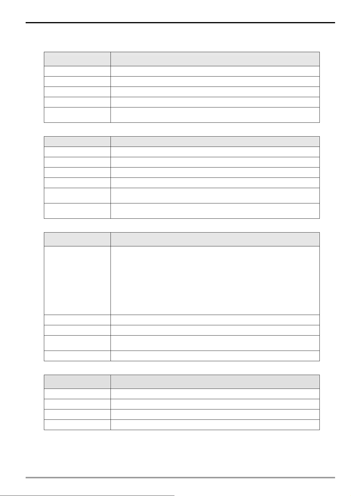
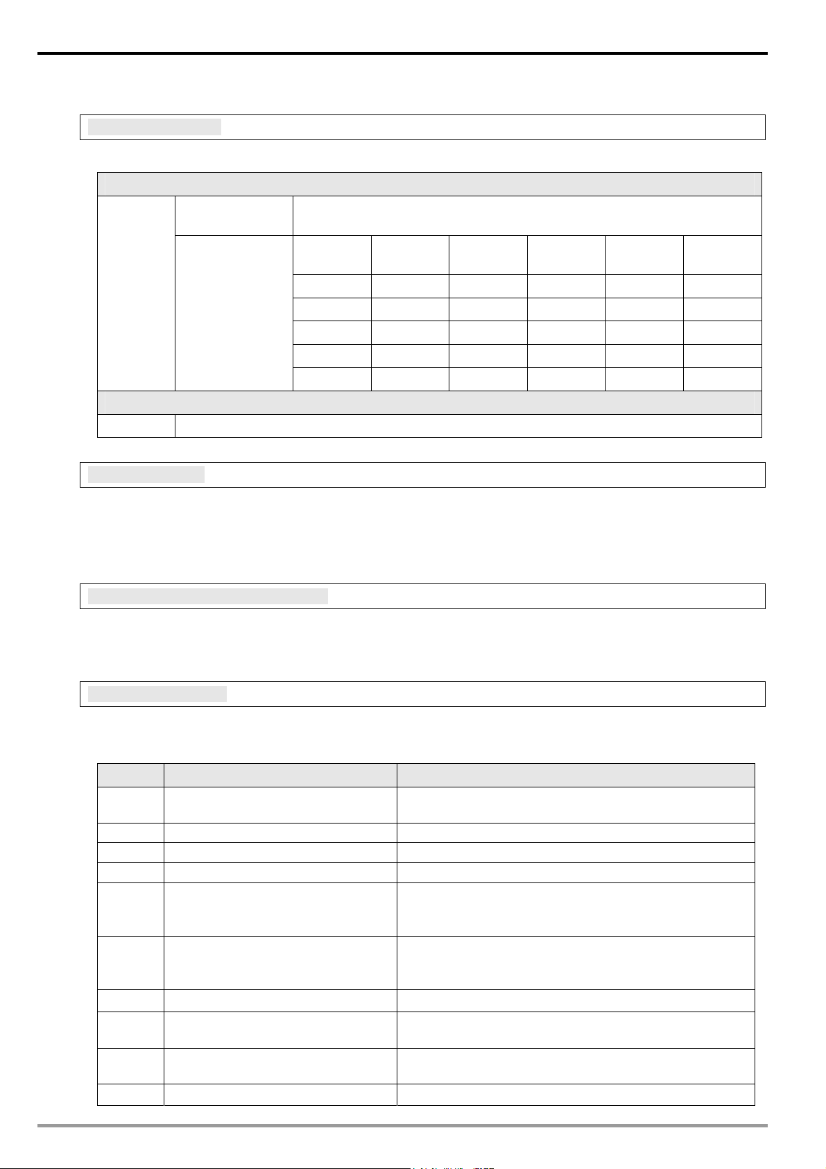
1.2 Specifications
Network interface
Item Specification
Interface RJ-45 with Auto MDI/MDIX
Number of ports 1 Port
Transmission method IEEE802.3, IEEE802.3u
Transmission cable Category 5e
Transmission speed 10/100 Mbps Auto-Detection
Communication
protocol
ICMP, IP, TCP, UDP, DHCP, SMTP, Modbus TCP, Ethernet/IP
Serial communication interface (COM1)
Item Specification
Interface Mini Dim
Number of ports 1 Port
Transmission method RS-232
Transmission cable DVPACAB215 / DVPACAB230 / DVPACAB2A30
Transmission speed 110, 150, 300, 600, 1200, 2400, 4800, 9600, 19200, 38400, 57600, 115200
Communication
protocol
4
Modbus, Delta Configuration, User Define
DVP-PLC Application Manual
Page 7
Ethernet Communication Module IFD9507
Serial communication interface (COM2)
Item Specification
Interface RJ-11
Number of ports 1 Port
Transmission method RS-485
Transmission speed 110, 150, 300, 600, 1200, 2400, 4800, 9600, 19200, 38400, 57600, 115200
Communication
protocol
Terminal block
Item Specification
Interface Feed-through terminal 10PIN
Transmission method RS-485
Transmission distance 1,200m
Transmission speed 110, 150, 300, 600, 1200, 2400, 4800, 9600, 19200, 38400, 57600, 115200
Communication
protocol
Max. number of
stations
Modbus, User Define
Modbus, User Define
32
Environment
Item Specification
ESD (IEC 61131-2, IEC 61000-4-2): 8KV Air Discharge
EFT (IEC 61131-2, IEC 61000-4-4): Power Line: ±2KV, Digital Input: ±2KV,
Communication I/O: ±2KV
Noise immunity
Operation temperature 0°C ~ 55 oC (temperature), 50 ~ 95% (humidity), pollution degree 2
Storage temperature -25°C ~ 70 oC (temperature), 5 ~ 95% (humidity)
Vibration/shock
immunity\
Certificates IEC 61131-2, UL508
Electrical specifications
Item Specification
Power voltage 24VDC (-15% ~ 20%) supplied by feed-through terminal
RS (IEC 61131-2, IEC 61000-4-3): 80MHz ~ 1GHz, 10V/m. 1.4GHz ~ 2.0GHz,
10V/m
Conducted Susceptibility Test (EN61000-4-6, IEC61131-2 9.10): 150KHz ~
80MHz, 3V/m
Surge Test (Biwave IEC61132-2, IEC61000-4-5):
Power line 0.5KV DM, Ethernet 0.5KV CM, RS-485 0.5KV CM
International standards: IEC61131-2, IEC 68-2-6 (TEST Fc)/IEC61131-2 &
IEC 68-2-27 (TEST Ea)
Power consumption 3W
Insulation voltage 500V
Weight (g) 140g
DVP-PLC Application Manual
5
Page 8
Ethernet Communication Module IFD9507
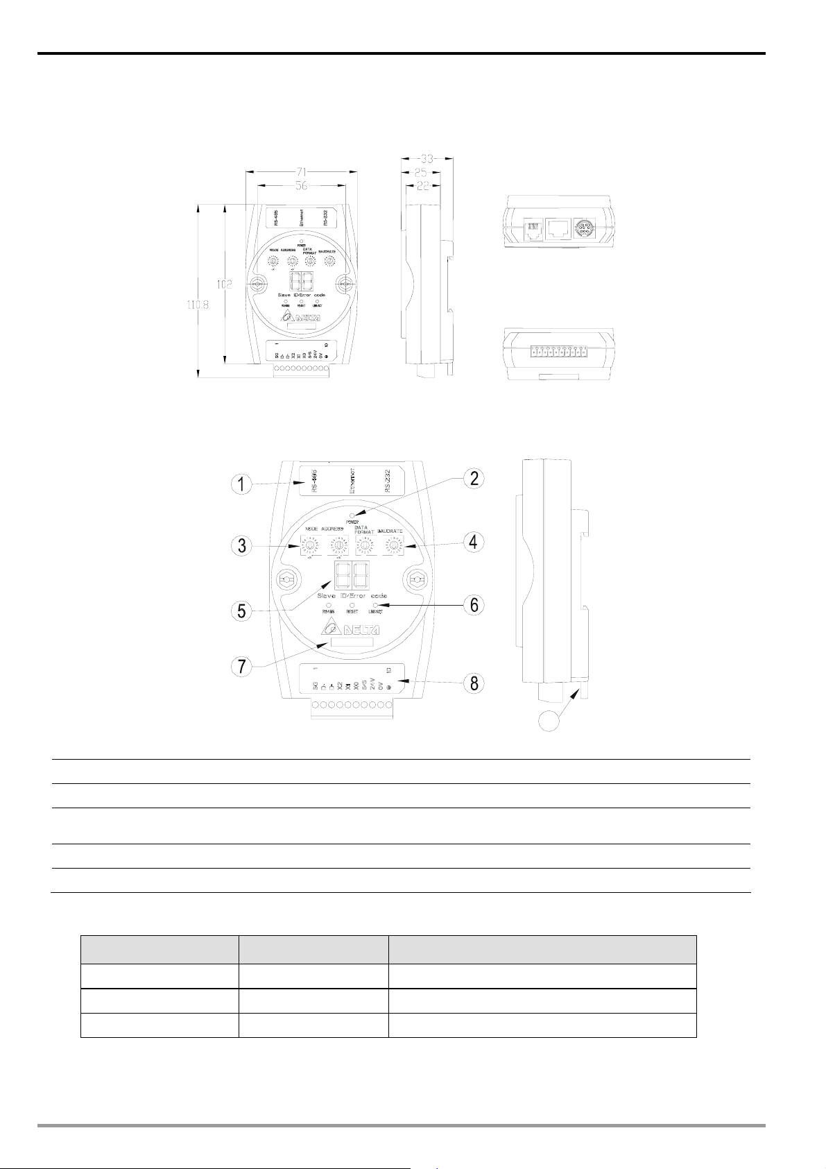
2 Product Profile & Outline
2.1 Dimension
Unit: mm
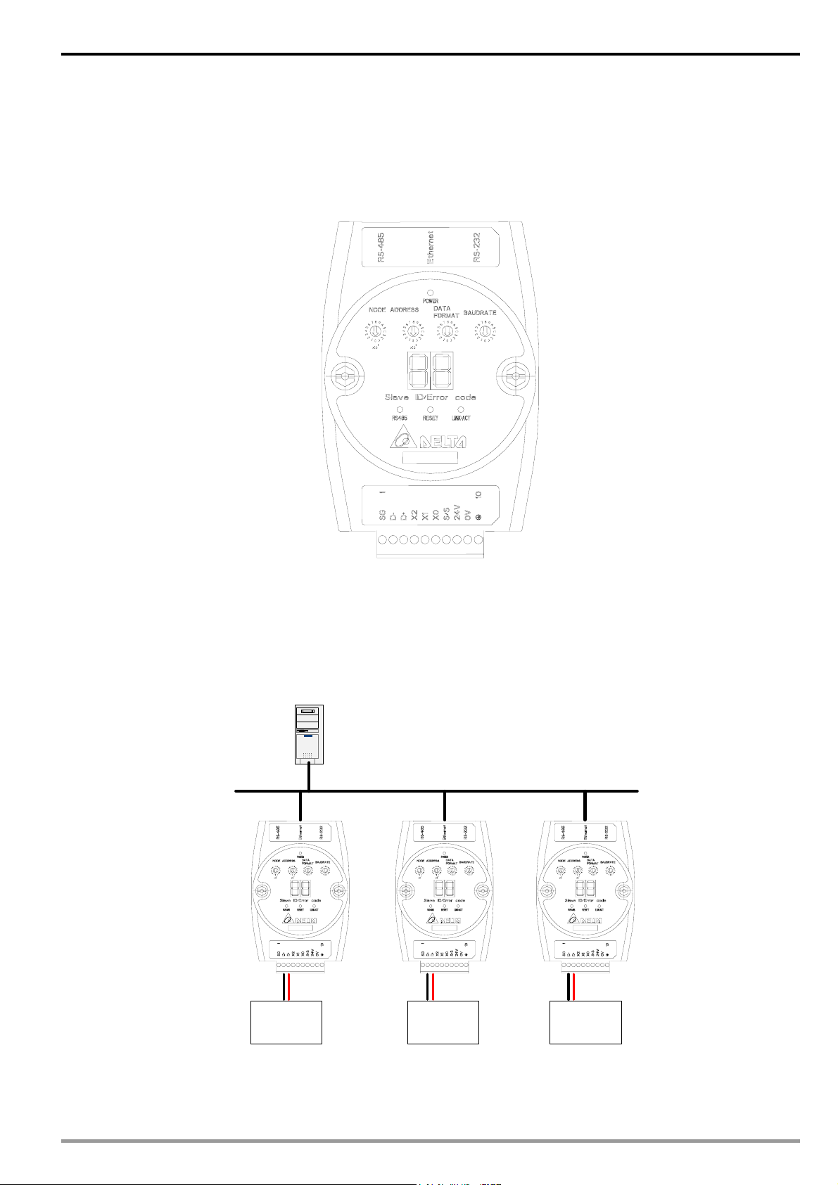
2.2 Product Profiles
9
1 Communication ports: RS-485, Ethernet, RS-232 6 RS-485 indicator, Reset button, Ethernet indicator
2 Power indicator 7 Module name
3 Address setup rotary switch。
4 Communication format/baud rate setup switch 9 DIN rail connector
5 Message display
8 RS-485 connector, digital input points, power input
point, earth point
2.3 LED Indicators
Name Color Function
POWER Green Power status
RS-485 Green Status of series communication port
LINK/ACT Green Status of network communication
6
DVP-PLC Application Manual
Page 9
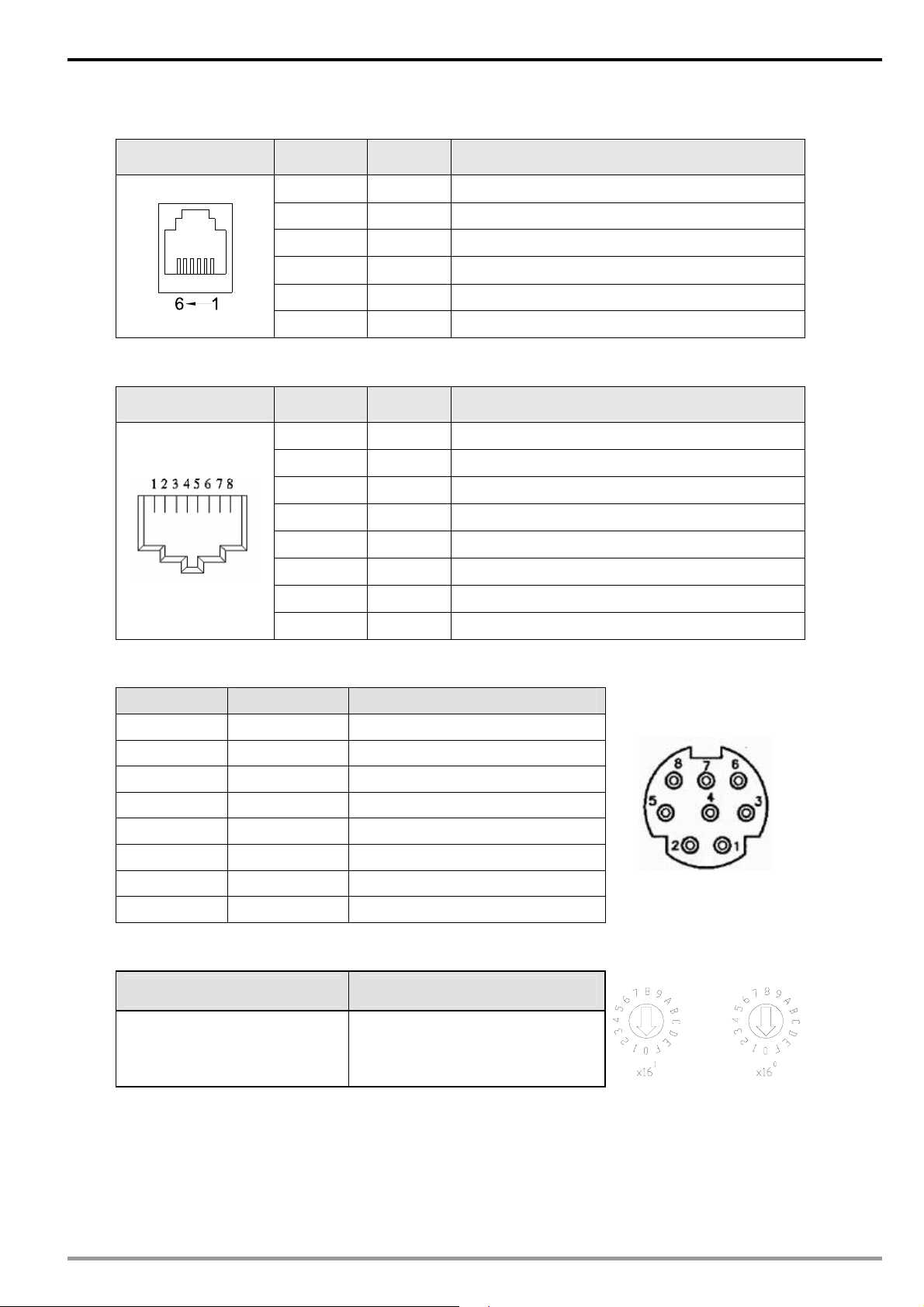
2.4 RJ-11 PIN Definition
RJ-11 sketch PIN. Signal Definition
Ethernet Communication Module IFD9507
1 -- N/C
2 -- N/C
3 D+ Positive pole for data
4 D- Negative pole for data
2.5 RJ-45 PIN Definition
RJ-45 sketch PIN Signal Definition
2.6 RS-232 PIN Definition
PIN Signal Content
1 -- N/C
2 -- N/C
3 -- N/C
4 Rx Reception data
5 Tx Transmission data
6 -- N/C
7 -- N/C
8 GND Ground
5 GND Reference
6 -- N/C
1 Tx+ Positive pole for data transmission
2 Tx- Negative pole for data transmission
3 Rx+ Positive pole for data receiving
4 -- N/C
5 -- N/C
6 Rx- Negative pole for data receiving
7 -- N/C
8 -- N/C
2.7 Address Switch
Switch setting Content
01…F7 Valid node address setting
DVP-PLC Application Manual
7
Page 10
Ethernet Communication Module IFD9507
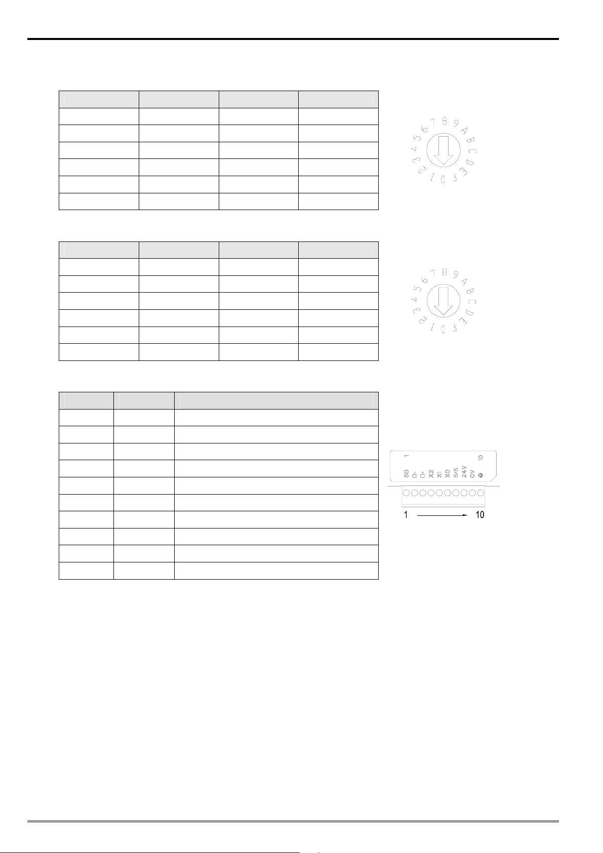
2.8 Data Format
Switch setting Format Switch setting Format
0 7-N-1 8 7-N-2
1 8-N-1 9 8-N-2
2 7-O-1 A 7-O-2
3 8-O-1 B 8-O-2
6 7-E-1 E 7-E-2
7 8-E-1 F 8-E-2
2.9 Baud Rate for Modbus Communication
Switch setting Baud rate Switch setting Baud rate
1 110 7 4,000
2 150 8 9,600
3 300 9 19,200
4 600 A 38,400
5 1,200 B 57,600
6 2,400 C 115,200
2.10 Feed-through Terminal PIN Definition
PIN Signal Content
1 SG Reference ground of signal
2 D- Data-
3 D+ Data-
4 X2 Digital input 2
5 X1 Digital input 1
6 X0 Digital input 0
7 S/S Reference ground of digital input
8 24V +24V input
9 0V 0V input
10 Earth ground
8
DVP-PLC Application Manual
Page 11
3 Installation & Wiring
This section gives instructions on how to connect IFD9507 with other devices and how to connect IFD9507 to
the network.
3.1 How to Install
Ethernet Communication Module IFD9507
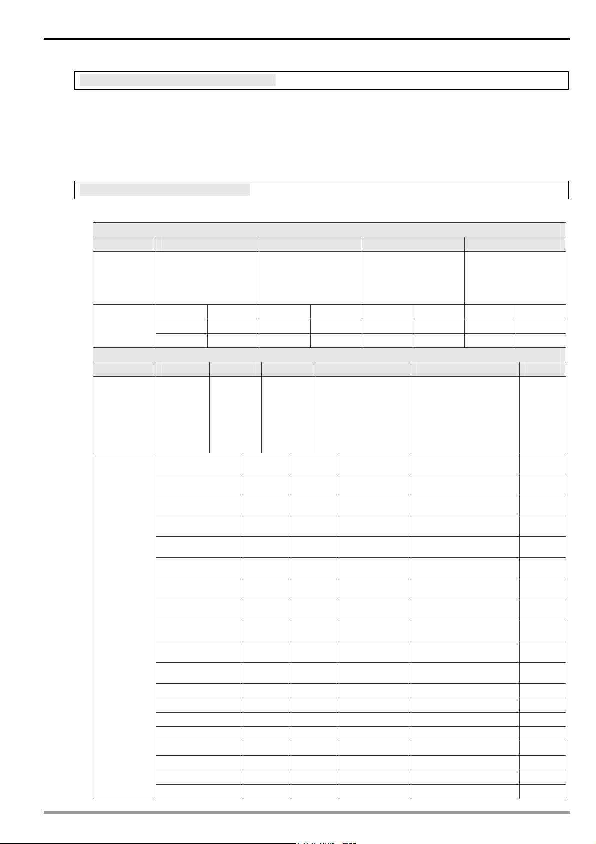
3.2 How to Connect IFD9507 to Network
Connect IFD9507 to the Ethernet hub by twisted pair cable CAT-5e. IFD9507 has auto MDI/MDIX function;
therefore, IFD9507 does not need to jump wire if selecting CAT-5e.The network connection between the PC and
IFD9507:
PC Master
Ethernet
DVP-PLC Application Manual
RS-485 (Master Mode)
AC motor
driver
RS-485 (Master Mode) RS-485 (Slave Mode)
Temperature
controller
Human
machine
interface
9
Page 12

Ethernet Communication Module IFD9507
4 Registers in IFD9507
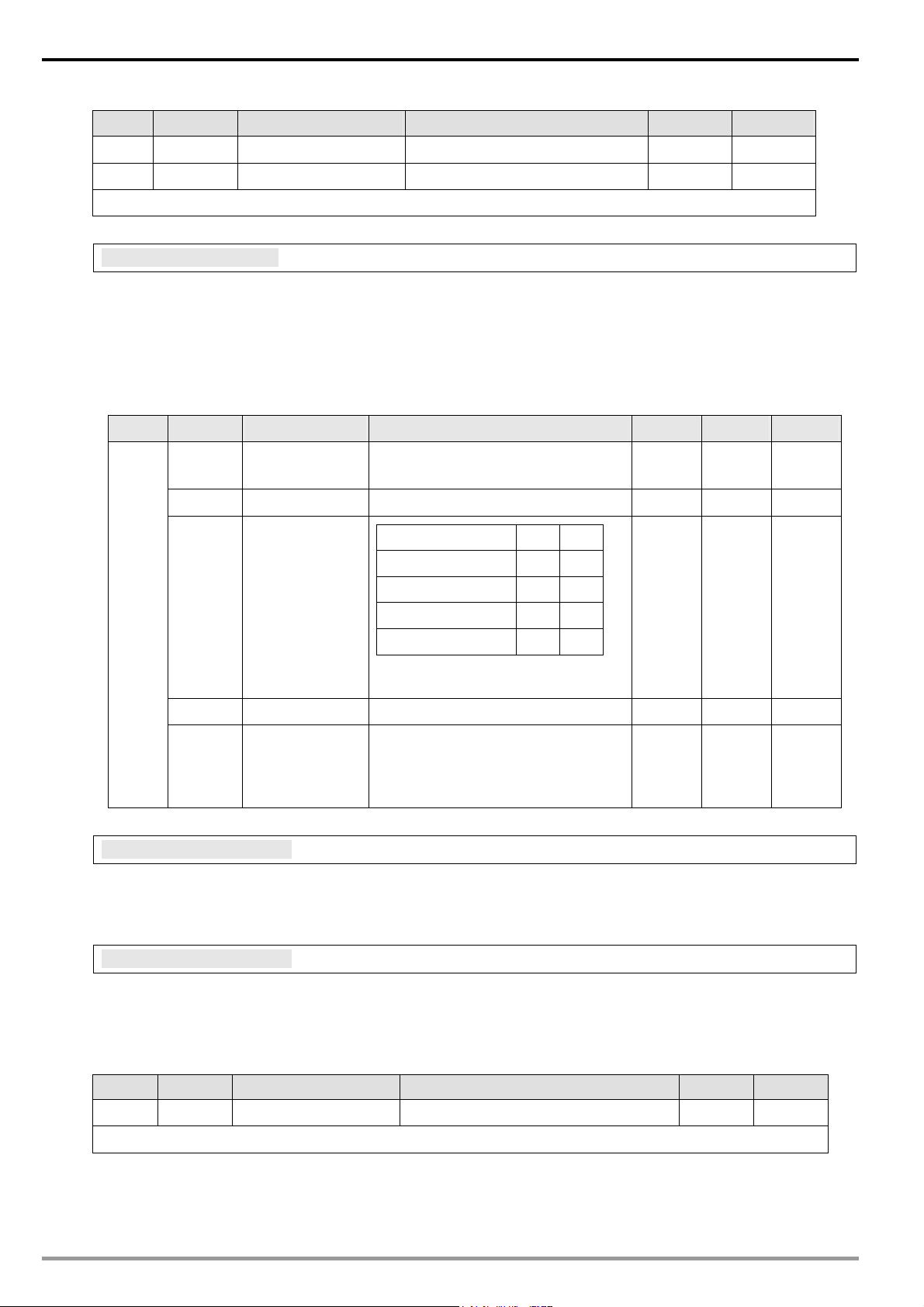
4.1 Basic Registers (BR)
BR#
Attribute
0 R Model name
1 R Firmware version
2 R
3 Reserved
4 R/W
5 R/W Baud rate See the table of baud rate setting No
6 R/W Address For setting up the station address No
7 R
8 Reserved
9 R Error code Displaying the errors. See the table of error codes. 0 No
10 Reserved
11 R/W
12 R/W
13 R/W Keep alive time
14 R/W I/O Enable Flag
15 R/W IP Index Destination IP index 1 Yes
Content Explanation
Set up by the system; read only. The model code of
IFD9507= H’0201
Displaying the current firmware version in hex, e.g. V1.2 is
indicated as high byte = 0x01 and low byte = 0x20.
Displaying the date in decimal form. 10,000s digit and
Release date of
the version
Communication
format
Number of
DI/DO points
Communication
time-out
Communication
delay time
1,000s digit are for “month”; 100s digit and 10s digit are for
“day”. For 1s digit: 0 = morning; 1 = afternoon.
Example: 12191 indicates the version released in the
afternoon of December 19.
See the table of communication format setting No
DI: high byte; DO: low byte 0x300 Yes
For setting up the communication time-out (unit: ms) in
Modbus
For setting up the minimum interval time between every
communication datum
For setting up the communication time-out (unit: second) in
TCP connections
High byte is input buffer enable flag. Low byte is output
buffer enable flag. The flag will be cleared when data was
sent.
Default Latched
Yes
Yes
Yes
5,000 Yes
0 Yes
30 Yes
0 No
16~32 Reserved
33 R/W
Symbol “R” refers to read only; “R/W” refers to read and write.
Returning to
default setting
0 No
4.2 Explanations on BR
BR#0: Model Name
Explanations:
1. Model code of IFD9507 = H'0201.
2. You can read the model code in the program to see if the extension module exists
BR#1: Firmware Version
Explanations:
The firmware version of IFD9507 is displayed in hex, e.g. H’0100 indicates version V1.00.
10
DVP-PLC Application Manual
Page 13
Ethernet Communication Module IFD9507
BR#2: Release Date of the Version
Explanations:
Displaying the date in decimal form. 10,000s digit and 1,000s digit are for “month"; 100s digit and 10s digit
are for “day". For 1s digit: 0 = morning; 1 = afternoon.
Example: 12191 indicates the version released in the afternoon of December 19.
BR#4: Communication Format
Explanations:
BR4 low byte
b7 ~ b4 b3 b2 ~ b1 b0
Stop bit
Explanation Reserved
0000 (0) 7-N-1 0011 (3) 8-O-1 1000 (8) 7-N-2 1011 (B) 8-O-2
Content
b7 B6 ~ b4 B3 b2 b1 b0
Explanation
0001 (1) 8-N-1 0110 (6) 7-E-1 1001 (9) 8-N-2 1110 (E) 7-E-2
0010 (2) 7-O-1 0111 (7) 8-E-1 1010 (A) 7-O-2 1111 (F) 8-E-2
RS-485
User
Define
0: Disable
1: Enable
Reserved
0: 1 stop bit
1: 2 stop bits
BR4 high byte
RS-232
User
Define
0: Disable
1: Enable
COM2 RS-485
setting
0: Serial Master
Ethernet Server
1: Serial Slave
Ethernet Client
Parity bit
00: none parity bit
01: odd parity bit
11: even parity bit
COM1 RS-232 setting
0: Delta Configuration
1: Modbus
Data bit
0: 7 data bits
1: 8 data bits
Mode
0: ASCII
1: RTU
Content
00000000 (0) Disable Disable Serial Master
00000001 (1) Disable Disable Serial Master
00000010 (2) Disable Disable Serial Master
00000011 (3) Disable Disable Serial Master
00000100 (4) Disable Disable Serial Slave
00000101 (5) Disable Disable Serial Slave
00000110 (6) Disable Disable Serial Slave
00000111 (7) Disable Disable Serial Slave
00001000 (8) Disable Enable Serial Master
: : : :
10000111 (135)
10001000 (136) Enable Enable Serial Master Delta configuration ASCII
10001001 (137) Enable Enable Serial Master Delta configuration RTU
10001010 (138) Enable Enable Serial Master Modbus ASCII
10001011 (139) Enable Enable Serial Master Modbus RTU
10001100 (140) Enable Enable Serial Slave Delta configuration ASCII
10001101 (141) Enable Enable Serial Slave Delta configuration RTU
10001110 (142) Enable Enable Serial Slave Modbus ASCII
10001111 (143) Enable Enable
Enable
Disable Serial Slave
Serial Slave Modbus RTU
Delta configuration
Delta configuration
Modbus
Modbus
Delta configuration
Delta configuration
Modbus
Modbus
Delta configuration
:
Modbus
ASCII
RTU
ASCII
RTU
ASCII
RTU
ASCII
RTU
ASCII
:
RTU
DVP-PLC Application Manual
11
Page 14
Ethernet Communication Module IFD9507
BR#5: Baud Rate
Explanations:
BR#5 low byte for baud rate of COM1
Communication
interface
Baud rate
(bps)
Content
RS-232
BR#5 high byte for baud rate of COM2
Content RS-485 same as low byte
Data
0x01 110 0x06 2,400 0x0B 57,600
0x02 150 0x07 4,800 0x0C 115,200
0x03 300 0x08 9,600
0x04 600 0x09 19,200
0x05 1,200 0x0A 38,400
Explanation
Data
Baud rate
(bps)
Data
Baud rate
(bps)
BR#6: Address
Explanations:
For filling in or reading the Modbus address. The address will be displayed in the message display after being
set up.
BR#7: Number of DI/DO Points
Explanations:
Read the number of DI/DO points from BR#7.
BR#9: Error Code
Explanations:
Error code = 0 refers to no error occurring.
Code Indication How to correct
01 ~ F7
F0 Returning to default setting -F1 IFD9507 being powered -F2 Power supply in low voltage Check if the power supply of the module works normally.
F3 Internal memory detection error
F4 Internal error. Manufacturing error.
F5 Network connection error Check if IFD9507 is connected normally to the network.
F6
F7 UART setting error.
E1 Alarm 1 triggered Check alarm input point 1.
Node address of the scan module
(when operating normally)
Full number of devices connected
in the network.
--
1. Re-power IFD9507. If the error still exists, try step 2.
2. Reset IFD9507. If the error still exists, send the
module back to the factory for repair.
1. Re-power IFD9507. If the error still exists, try step 2.
2. Reset IFD9507. If the error still exists, send the
module back to the factory for repair.
Check if the number is too much.
Check if the RS-485, RS-232 communication format is
correct.
12
DVP-PLC Application Manual
Page 15

Ethernet Communication Module IFD9507
Code Indication How to correct
E2 Alarm 2 triggered Check alarm input point 2.
E3 Alarm 3 triggered Check alarm input point 3.
1. Check if IFD9507 is normally connected to RS-485.
04 CRC error
0B No response from the station
BR#11: Communication Time-out (ms)
Explanations:
or setting up the communication time-out in Modbus. Default = 5,000ms. For example, if you wish to set up
the communication time-out as 7 seconds manually, write 7,000 into BR11.
BR#12: Communication Delay Time (ms)
2. Make sure the transmission speed of IFD9507 is
consistent with that of other nodes on the network.
1. Check if IFD9507 is normally connected to RS-485.
2. Make sure the transmission speed of IFD9507 is
consistent with that of other nodes on the network.
Explanations:
For setting up the minimum interval time between every Modbus communication datum. Default = 0ms. For
example, if you wish to set up the communication delay time as 100ms manually, write 100 into BR12.
BR#13: Keep Alive Time (s)
Explanations:
For setting up the communication time-out in TCP connections. Default = 30s. For example, if you wish to set
up the communication time-out as 7 seconds manually, write 7 into BR13.
BR14: I/O Enable Flag
Explanations:
Setting up input buffer and output buffer enable or not. Default = 0. Setting high byte to 1 can enable input
buffer and setting low byte to 1 can enable output buffer.
BR15: IP index
Explanations:
Destination IP index is used in a TCP connection. Default = 1. In delta DCISoft, there are 4 items can be set
therefore the index is 1 to 4. User can select one of items to connect with others Ethernet/IP device.
BR#33: Returning to Default Setting
Explanations:
IFD9507 will return to default setting when "1” is written into BR#33. BR#33 will be cleared to “0” automatically
after the returning.
4.3 Alarm Registers (AL) in IFD9507
AL# Attribute Content Explanation Default Latched
0 R/W Alarm point 1 0 Yes
DVP-PLC Application Manual
13
Page 16
Ethernet Communication Module IFD9507
AL# Attribute Content Explanation Default Latched
1 R/W Alarm point 2 0 Yes
2 R/W Alarm point 3 0 Yes
Symbol “R” refer to read only; “R/W” refers to read and write.
AL#0: Alarm Point 1
Explanations:
You can designate one RX extension point as the alarm point by setting up the AL register in IFD9507. When
the alarm point is triggered, IFD9507 will execute its corresponding function. When b15 of AL0 is set as “1”,
the Gateway will execute the event immediately. When RX point is triggered, the Gateway will only execute
the triggered event once.
Device Function Setting Attribute Default Latched
b15
b4 ~ b14 Reserved
b2 ~ b3
AL#0
b1 Reserved Reserved
b0
Enabling the
function
Type of event
enabled when
RX alarm point
is triggered
Condition for
triggering RX
b15 = 1: Enabling
b15 = 0: Disabling
b3 b2
Reserved 0 0
Trigger E-Mail 0 1
Reserved 1 0
Reserved 1 1
The setting will be invalid when
thealarm function is being executed.
b0 = 0: Triggered when RX input
point is low
b0 = 1: Triggered when RX input
point is high
R/W 0 Yes
R/W 0 No
R/W 0 Yes
R/W 0 Yes
AL#1: Alarm Output 2
Explanations:
The settings for AL#1 are the same as those in AL#0.
AL#2: Alarm Output 3
Explanations:
The settings for AL#2 are the same as those in AL#0.
4.4 In buffer registers (IN) in IFD9507
IN# Attribute Content Explanation Default Latched
0~255 R/W Data input buffer Ethernet/IP input data 0 No
Symbol “R” refers to read only; “R/W” refers to read and write.
Explanations:
The input data was sent to Ethernet.
14
DVP-PLC Application Manual
Page 17
4.5 Out buffer registers (OUT) in IFD9507
OUT# Attribute Content Explanation Default Latched
0~255 R Data output buffer 0 No
Symbol “R” refers to read only; “R/W” refers to read and write.
Explanations:
The output data was sent to RS-485.
5 Monitoring Functions
5.1 Monitor Bit Registers (MB)
MB# Attribute Content Explanation Default Latched
0 R/W
1 R/W
2 R/W
3 ~ 32 R/W
33 ~ 200 R/W Reserved
201 R Monitored value
202 ~ 213 R Reserved
214 R Monitored status
Symbol “R” refer to read only; “R/W” refers to read and write.
MB#0: Number of Devices Monitored
Number of devicees
monitored
No. of station
monitored
Address of the
device monitored
No. of station
monitored, address
of the device
monitored
Ethernet Communication Module IFD9507
Cache mode normally enabled (b15=1),
monitoring data in max. 16 slaves.
No. of the station to be monitored 0 Yes
Recording the address of the device
monitored.
No. of the station to be monitored;
recording the address of the device
monitored.
Every MB records the value in the 16-bit
device.
Every MB records the status in the 16-bit
device. 1 = normal; 0 = abnormal
0 Yes
0 Yes
0 Yes
0 No
0 No
Explanations:
For setting up the number of devices to be monitored. Max. data in 16 slaves can be monitored.
b15 is read only (Default =1: normally enabled cache mode)
MB# (Odd Number): No. of Station Monitored
Explanations:
MB#1, MB#3, MB#5…MB#33 are for setting up the station No. (0 ~ 255) to be monitored.
MB# (Even Number): Address of Device Monitored
Explanations:
MB#2, MB#4, MB#6…MB#34 are for setting up the address of the device to be monitored.
MB#201: Monitored Value
Explanations:
Every MB records the values in the 16-bit device.
DVP-PLC Application Manual
15
Page 18

Ethernet Communication Module IFD9507
b15 b14 b13 b12 b11 b10 b9 b8 b7 b6 b5 b4 b3 b2 b1 b0
Device
MB#214: Monitored Status
Explanations:
Every MB records the status in the 16-bit device. 1 = normal; 0 = abnormal.
Device
5.2 Monitor Word Registerss (MW)
33 ~ 200 R/W Reserved
201 ~ 216 R Monitored value
216 ~ 300 R Reserved
Symbol “R” refers to read only; “R/W” refers to read and write.
Device
16
b15 b14 b13 b12 b11 b10 b9 b8 b7 b6 b5 b4 b3 b2 b1 b0
Device
16
15
15
Device
14
Device
14
Device
13
Device
13
Device
12
Device
12
Device
11
Device
11
Device
10
Device
10
Device 9 Device 8 Device 7 Device 6 Device 5 Device 4 Device 3 Device 2 Device
Device 9 Device 8 Device 7 Device 6 Device 5 Device 4 Device 3 Device 2 Device
MW# Attribute Content Explanation Default Latched
0 R/W
1 R/W
2 R/W
Number of devices
monitored
No. of station
monitored
Address of the
device monitored
Cache mode normally enabled (b15=1),
monitoring data in max. 16 slaves.
No. of the station to be monitored 0 YES
Recording the address of the device
monitored
No. of station
3 ~ 32 R/W
monitored, address
of the device
No. of the station to be monitore; recording
the address of the device monitored.
monitored
Every MW records the monitored value in 1
register
301 R Monitored status
Every MW records the status in a 16-bit
register. 1 = normal; 0 = abnormal
1
1
0 YES
0 YES
0 YES
0 NO
0 NO
16
MW#0: Number of Devices Monitored
Explanations:
For setting up the number of devices to be monitored. Max. data in 16 slaves can be monitored.
b15 is read only (Default =1: normally enabled cache mode)
MW# (Odd Number): No. of Station Monitored
Explanations:
MW#1, MW#3, MW#5…MW#33 are for setting up the station No. (0 ~ 255) to be monitored.
MW# (Even Number): Address of Device Monitored
Explanations:
MW32, MW34, MW#36…MW#34 are for setting up the address of the device to be monitored.
MW#201~#216: Monitored Value
DVP-PLC Application Manual
Page 19
Ethernet Communication Module IFD9507
Explanations:
Every MW records the values in 1 register.
MW#201 MW#202 MW#203 MW#204 MW#205 MW#206 MW#207 MW#208 MW#209 MW#210
Device 1 Device 2 Device 3 Device 4 Device 5 Device 6 Device 7 Device 8 Device 9 Device 10
MW#211 MW#212 MW#213 MW#214 MW#215 MW#216
Device
11
Device
12
Device
13
Device
14
Device
15
Device
16
MW#301: Monitored Status
Explanations:
Every MW records the status in a 16-bit register. 1 = normal; 0 = abnormal.
b15 b14 b13 b12 b11 b10 b9 b8 b7 b6 b5 b4 b3 b2 b1 b0
Device
16
Device
15
Device
14
Device
13
Device
12
Device
11
Device
10
Device 9 Device 8 Device 7 Device 6 Device 5 Device 4 Device 3 Device 2 Device
1
6 Setting up Device Address and Relay Address in Slave Mode (For Modbus TCP protocol
only)
MIP# Attribute Content Explanation Default Latched
0 ~ 50 R/W
Corresponding
address
50 ~ 249 R/W Relay IP address
Symbol “R” refers to read only; “R/W” refers to read and write.
MIP#0: Corresponding Address
Explanations:
The low bytes of MIP#0 are for the first address, and the high byte are for the second address, and so on.
MIP#51 ~ #52: Corresponding IP for the 1st Device Address
Explanations:
Example 1: If you wish to convert “192.168.0.1” into C0A80001 (hex), write A8C0 into MIP50 and H0100 into
MIP51.
Max. 100 addresses are allowed. High
byte for 1 address and low byte for 1
address.
Total 100 IPs. Every address (1 byte)
corresponds to 1 IP address (4 bytes).
0 Yes
0 Yes
Example 2: Data in address 1 have to correspond to 192.168.0.8. Data in address 2 have to correspond to
192.168.0.6. To complete such settings, write H0102 into MIP0, H0800 into MIP50, HA8C0 into MIP51, H0600
into MIP52, and HA8C0 into MIP53.
7 Setting up Device Address and Other Network Settings in Slave Mode
Parameter Explanation
Device address Address of Modbus device
Relay IP address Corresponding IP address for a device
Priority/Time Tick Scale of time. Unit: ms
Timeout Tick Scale of timeout
Timeout Timeout = Time Tick × Timeout Tick (Unit: ms)
DVP-PLC Application Manual
17
Page 20
Ethernet Communication Module IFD9507
Parameter Explanation
Multiple Max. timeout times
Trigger Cyclic, changing status, application object
OÆT packet interval Packet interval between originator and target
TÆO packet interval Packet interval between originator and target
8 Modbus Communication
8.1 Function Codes Supported
Function code Explanation Devices supported
0x02 Read discrete input RX
0x03 Read holding register BR, AL, MB, MW, MIP
0x06 Write single holding register BR, AL, MB, MW, MIP
0x10 Write multiple holding register BR, AL, MB, MW, MIP
0x17 Read/write multiple holding register BR, AL, MB, MW, MIP
8.2 Exception Codes Supported
Exception code Explanation
0x01 Illegal function
0x02 Illegal data addresss
0x03 Illegal data value
0x04 Slave device failure
0x0A Gateway path unavailable
0x0B Gateway target device failed to respond
8.3 Device Type & Device Address
Device
type
RX 0x0400 ~ 0x0402 11025 ~ 11027 101025 ~ 101027 3
Device
type
BR 0x0000 ~ 0x00FF 40001 ~ 40256 400001 ~ 400256 64
AL 0x0200 ~ 0x0202 40513 ~ 40515 400513 ~ 400515 3
X 0x0400 ~ 0x0402 41025 ~ 41027 401025 ~ 401027 3
IN 0x0500 ~ 0x05FF 41281 ~ 41536 401281 ~ 401536 256
OUT 0x0600 ~ 0x06FF 41537 ~ 41791 401537 ~ 401791 256
MB 0x2000 ~ 0x20FF 48193 ~ 48448 408193 ~ 408448 256
MW 0x2200 ~ 0x23FF 48705 ~ 49216 408705 ~ 409216 512
MIP 0x2400 ~ 0x24FF 49217 ~ 49471 409217 ~ 409471 256
Modbus address
(Hex)
Modbus address
(Hex)
Discrete input
5-digit Modbus address (Dec)
Holding register
5-digit Modbus address (Dec)
6-digit Modbus address
(Dec)
6-digit Modbus address
(Dec)
Number
Number
18
DVP-PLC Application Manual
Page 21

9 Ethernet/IP Communication
9.1 Service code supported
Ethernet Communication Module IFD9507
Service
Code
ID
Message Router Object
Assembly Object
Connection Manager
Object
0x01
0x05 ID Reset Invokes the Reset service for the device.
0x0E
0x10
0x4E
0x54
BR
AL
MB
MW
TCP Interface
TCP Link
ID
Message Router Object
Assembly Object
Connection Manager
Object
BR
AL
MB
MW
TCP Interface
TCP Link
Assembly Object
BR
AL
MB
MW
TCP Interface
Connection Manager
Object
Connection Manager
Object
Object Service Description
Get_Attribute_All Returns a predefined listing of this objects
attributes
Get_Attribute_Single Return the contents of the specified
attribute.
Set_Attribute_Single Used to modify an attribute.
Forward_Close Closes a connection.
Forward_Open Opens a connection, maximum data size
is 511 bytes.
9.2 Object supported
Object Name Class ID Code Instance Code
ID 0x01 0x01 Identity Attribute Get
Message Router Object 0x02 0x01 Router Command
Assembly Object
Connection Manager Object 0x06 0x01 Connection
RX Digital input Discrete input Get
BR 0x64 0x01 Basic registers Attribute Get/Set
AL 0x64 0x02 Alarm function Attribute Get/Set
MB 0x64 0x03 Bit monitor Attribute Get/Set
MW 0x64 0x04 Register monitor Attribute Get/Set
TCP Interface 0xF5 0x01 TCP/IP Interface
DVP-PLC Application Manual
Function
Description
0x04 0x64 Assembly GO Set
0x04 0x65 Input device object GI Get
monitor object
Object
Object Type Attribute
Attribute Get/Set
19
Page 22

Ethernet Communication Module IFD9507
Object Name Class ID Code Instance Code
TCP Link 0xF6 0x01 TCP/IP Link
Function
Description
Object
Object Type Attribute
Object Get
9.3 CIP General Status Code (Reference Volume 1:CIP Common Specification Appendix B)
General
Status Code
(in hex)
00 Success Service was successfully performed by the object specified.
01 Connection failure A connection related service failed along the connection path.
02 Resource unavailable Resources needed for the object to perform the requested
04 Path segment error The path segment identifier or the segment syntax was not
05 Path destination
08 Service not supported The requested service was not implemented or was not
09 Invalid attribute value Invalid attribute data detected
0E Attribute not settable A request to modify a non-modifiable attribute was received.
13 Not enough data The service did not supply enough data to perform the
14 Attribute not supported The attribute specified in the request is not supported
15 Too much data The service supplied more data than was expected
16 Object does not exist The object specified does not exist in the device.
20 Invalid parameter A parameter associated with the request was invalid. This code
26 Path Size Invalid The size of the path which was sent with the Service Request
Status Name Description of Status
service were unavailable
understood by the processing node. Path processing shall stop
when a path segment error is encountered.
The path is referencing an object class, instance or structure
unknown
element that is not known or is not contained in the processing
node. Path processing shall stop when a path destination
unknown error is encountered.
defined for this Object Class/Instance.
specified operation.
is used when a parameter does not meet the requirements of
this specification and/or the requirements defined in an
Application Object Specification.
is either not large enough to allow the Request to be routed to
an object or too much routing data was included.
9.4 Connection Manager Service Request Error Codes (Reference Volume 1:CIP Common Specification
Table3-5.29)
General
Status
0x00 Service completed successfully
0x01 0x0100 CONNECTION IN USE OR DUPLICATE FORWARD OPEN
0x01 0x0103 TRANSPORT CLASS AND TRIGGER COMBINATION NOT
0x01 0x0108 INVALID NETWORK CONNECTION PARAMETER
20
Extended Status Explanation and Description
This extended status code shall be returned when an originator is
trying to make a connection to a target with which the originator may
have already established a connection
SUPPORTED
A transport class and trigger combination has been specified which
is not supported by the target. Routers shall not fail the connection
based on the transport class and trigger combination. Only targets
shall return this extended status code.
This extended status code shall be returned as the result of
specifying a connection type, connection priority, redundant owner
or fixed / variable that is not supported by the target application.
Only a target node shall return this extended status code.
DVP-PLC Application Manual
Page 23

Ethernet Communication Module IFD9507
General
Status
0x01 0x0114 VENDOR ID OR PRODUCT CODE MISMATCH
0x01 0x0115 PRODUCT TYPE MISMATCH
0x01 0x0116 REVISION MISMATCH
0x01 0x0315 INVALID SEGMENT IN CONNECTION PATH
Extended Status Explanation and Description
The Product Code or Vendor Id specified in the electronic key
logical segment does not match the Product Code or Vendor Id of in
the target device.
The Product Type specified in the electronic key logical segment
does not match the Product Type of in the target device.
The major and minor revision specified in the electronic key logical
segment does not correspond to a valid revision of the target
device.
Invalid Segment Type or Segment Value in Connection Path This
extended status code is the result of a device being unable to
decode the connection path. This could be caused by an
unrecognized path type, a segment type occurring unexpectedly, or
a myriad of other problems in the connection path.
10 Setting up the Software - DCISoft
This section gives instructions on how to set up IFD9507 by DCISoft and explanations on each setup page.
IFD9507 is set up by UDP port 20006; therefore, you have to be aware of the relevant settings of the firewall.
See the explanations below on the software.
10.1 Setting up Communication & Searching for Modules in DCISoft
Broadcast search
1. Open DCISoft on the PC and click on the “IP Search” icon.
2. You will see the network modules found.
DVP-PLC Application Manual
21
Page 24

Ethernet Communication Module IFD9507
3. Double-click on the module to be set up to enter the setup page. The first page overviews the basic
status of the module.
22
4. The next page is for basic network setup. Consult your ISP for relevant network settings. For other
settings, see BR4~BR6 and BR11~BR13.
DVP-PLC Application Manual
Page 25

Ethernet Communication Module IFD9507
10.2 Basic Settings
The basic settings include parameters such as module name, network settings and serial communication.
The basics
1. Module name:
There can be many IFD9507s on the network. Thus, you can set up a module name for each module to
DVP-PLC Application Manual
23
Page 26

Ethernet Communication Module IFD9507
identify the module when you need to use them.
2. Master configuration:
Open “Serial Master” mode or “Serial Slave” mode.
3. Network settings:
Enable DHCP or static IP. Consult your ISP for other relevant settings.
A. IP configuration:
There are 2 types of IP, static IP and DHCP.
Static IP: Preset or manually modified by the user.
DHCP: Automatically updated by the server. There has to be a server in the LAN.
IP Explanation
Static The user enters the IP address, subnet mask and gateway.
DHCP DHCP server offers the IP address, subnet mask and gateway.
B. IP address:
IP address is the location of the equipment on the network. All equipment connected to the network
has to have an IP address. Incorrect IP address will result in connection failure on the equipment or
even other equipment. Ask your ISP for questions about IP address setup. The default IP for
IFD9507 is 192.168.1.5.
C. Subnet mask:
Subnet mask is an important parameter for setting up the subnet, used for seeing if the destination
IP and the local equipment are in the same subnet. If not, the equipment will send the packet to the
gateway, and the gateway will send the packet to another subnet. Incorrect setting may cause the
destination equipment unable to communication to IFD9507. To see of your setting is correct,
conduct bitwise AND operations between your IP and subnet mask and destination IP and subnet
mask. If the two values obtained are the same, the two IPs are in the same subnet. The default
subnet mask of IFD9507 is 255.255.255.0.
D. Gateway:
Gateway is the window for two different subnets, allowing the two ends in different subnets to
communicate. For example, if the LAN has to be connected to WAN, it will need a gateway to
bridge the communication. The IP of the gateway has to be in the same subnet as IFD9507. The
default gateway of IFD9507 is 192.168.1.254.
4. Communication parameter setting:
See how to set up BR4, BR5, and BR6.
Applicable protocol: Modbus/TCP or Ethernet/IP.
5. Timer setting:
For setting up TCP communication idle time, communication timeout and minimum delay time for
every communication datum. Please refer to the settings of BR11, BR12 and BR13.
10.3 Network Settings
The first step for all the network equipment to connect to the network is to have its own IP address (Internet
Protocol). The IP address is like a number for all network equipment to be identified in the network.
Setting up static IP of the PC
24
DVP-PLC Application Manual
Page 27

Ethernet Communication Module IFD9507
1. Enter Control Panel → Network Connection → click on “Local Area Connection”.
2. You will see the “Local Area Connection Status” window. Click on “Properties”.
3. Click on “Internet Protocol (TCP/IP)".
4. Enter “192.168.0.1” into IP address. Click on “OK” to complete the IP address setting of the PC.
DVP-PLC Application Manual
25
Page 28

Ethernet Communication Module IFD9507
10.4 Setting up E-Mails
E-Mail is the abbreviation of electronic mail which transmits mails through the network. IFD9507 has E-Mail
functions for the user to pre-save a segment of text message, which can be a descriptive message or error
message, into the subject of the E-Mail. When the E-Mail is triggered, IFD9507 will send the messages to the
user by E-Mail.
Mail settings
26
1. Mail alarm setup:
There are 3 mail alarms to be set up. Check the boxes to enable the alarms. The alarm can be
triggered by “low" and “high”.
2. SMTP server:
When alarm 1 is triggered, the E-Mail will first be sent to SMTP server, and the SMTP server will send
it to the designated address. For example, assume there is an E-Mail to be sent to
DVP-PLC Application Manual
Page 29

Ethernet Communication Module IFD9507
Test@delta.com.tw
first, and the server will further send it to the recipient Test@delta.com.tw
3. E-Mail of sender:
Maximum 63 Engligh characters are allowed.
4. Subject of E-Mail:
You can enter the text message in the column, and the message will be placed in the subject of the
E-Mail and sent to the recipient. IFD9507 is able to contain 1 ~ 3 E-Mail subjects (max. 63 English
characters are allowed).
5. E-Mail of recipient:
One mail can be sent to 10 addresses according to the alarm settings. Every address allows max.63
English characters. For example, (see the figure above) when Alarm 1 is triggered, the E-Mail will be
sent to Test1@delta.com.tw
sent to Test2@delta.com.tw
Note:
To correctly send out E-Mails, there has to be a SMTP server in the network. When we send out an
E-Mail, the mail will be sent to SMTP server first, and the server will further send the mail to the
designated address.
, and the SMTP server is 192.168.0.1. The E-Mail will be sent to the SMTP server
.
and Test2@delta.com.tw . When Alarm 2 is triggered, the E-Mail will be
10.5 Monitoring Settings
You can read data in designated addresses in different equipment in the network by setting up IFD9507.The
data can be temporarily stored in IFD9507 for fast storing and acquisition.
Setting up monitoring functions
1. Monitor bit:
Device addresses for setting up the bit status of serial slave; able to read the content in the
DVP-PLC Application Manual
27
Page 30

Ethernet Communication Module IFD9507
corresponding address of the designated slave.
2. Monitor word:
Device addresses for setting up the word status of serial slave; able to read the content in the
corresponding address of the designated slave.
Note:
Cache mode normally enabled, and Max. data in 16 slaves can be monitored. When the cache mode
is enabled, the data you would like to read will be sent back directly from the register in IFD9507.
3. Serial slave mode (used when in Modbus TCP protocol):
The instruction sent from the master is received and transferred to the network. Please designate the
10.6 IP Filter
The IP filter is used for restricting the connection of the network in case some uncertain IP will cause errors.
Only the IP set within a certain range can establish a connection. Other IPs will be rejected.
Setting up IP filter
station address and relay IP address.
Station address: slave PLC address (Gateway and PLC address cannot be the same)
Relay IP address: serial master IP
28
DVP-PLC Application Manual
Page 31

Ethernet Communication Module IFD9507
1. Enable IP filter function:
Check the box to enable IP filter.
2. IP address:
IP addresses that are allowed to establish connections. Maximum 8 IPs are allowed.
3. Netmask:
Subnet mask of the IP that is allowed to establish a connection. To see whether the subnet mask is
allowed, conduct bitwise AND operation between the allowed IP and subnet mask and destination IP
and subnet mask. If the two values obtained are the same, the subnet mask is allowed by the network.
For example, assume the IP is 192.168.0.1 and subnet mask 255.255.255.255, the only IP allowed to
establish a connection will be 192.168.0.1. If the subnet mask is 255.255.255.0, the IPs allowed to
establish connections will become 192.168.0.0 ~ 192.168.0.255.
10.7 Ethernet/IP settings
Ethernet/IP parameters are used for a connection.
Setting Ethernet/IP parameters
DVP-PLC Application Manual
29
Page 32

Ethernet Communication Module IFD9507
30
1. Dest IP
This is Destination IP address.
2. Timeout (ms)
Timetick * Timeout tick = Timeout
※ Available time tick: 20 ~ 215
DVP-PLC Application Manual
Page 33

Ethernet Communication Module IFD9507
※ Max. Timeout tick: 255
3. Trigger
There are three trigger types. The cyclic used to describe event that repeat in regular. Production
occurs when a change of state is detected by application object. The Application object used to
provide the run time exchange of messages across network.
4. OÆT RPI
Originator to target requested packet interval.
When the trigger occurs, the packet is sent to the target within the set interval time.
5. TÆO RPI
Target to originator requested packet interval.
When the trigger occurs, the packet is sent to the source within the set interval time.
6. In Instance
Target input buffer Instance. Range: 1 ~ 65,535.
7. In Size
Target input buffer size. Range: 0 ~ 256.
8. Out Instance
Target output buffer instance. Range: 1 ~ 65,535.
9. Out Size
Target output buffer size. Range: 0 ~ 256.
10. Width
Data width
11. Config Instance
Configuration instance. Range: 1 ~ 65,535.
10.8 User Defined Settings
When you set up user-defined communication protocol for IFD9507, please set up the following parameters.
Setting up communication parameter between RS-232/RS-485 serial master and serial slave
DVP-PLC Application Manual
31
Page 34

Ethernet Communication Module IFD9507
32
1. Listen Port/Destination IP:
Range: 1,024 ~ 65,535
2. Fix Length:
Length of the packet to be transmitted. Unit: byte
3. Start Item:
DVP-PLC Application Manual
Page 35

1 ~ 3 bytes of characters as the start of a packet.
4. Stop Item:
1 ~ 3 bytes of characters as the stop of a packet.
10.9 Virtual COM
Virtual COM converts the data transmitted to RS-232 to Ethernet.
Select "User Define COM”.
Ethernet Communication Module IFD9507
Switch to “User Define” page and select “Listen Port”.
DVP-PLC Application Manual
33
Page 36

Ethernet Communication Module IFD9507
Open Virtual COM setup page.
34
DVP-PLC Application Manual
Page 37

Ethernet Communication Module IFD9507
Press “OK”, and you will see all the devices connected on the network.
Select the module you need and press “OK”. Relevant information of the device will be imported
automatically. Press “OK” to complete the setup.
Once the setup is successful, you can see the virtual COM you set in the Device Manager.
DVP-PLC Application Manual
35
Page 38

Ethernet Communication Module IFD9507
10.10 Security Settings
To prevent the set values in IFD9507 from being modified, you can set up passwords to lock the settings in
IFD9507.
Setting up password
36
1. Password setup:
Check the "Modify” box to set up the password.
2. Confirm password:
Enter the new password again.
3. See “12.1 Application Examples” for more details.
DVP-PLC Application Manual
Page 39

Note:
Once the password is locked, all the pages cannot be set up unless you unlock the password.
However, if you set up IFD9507 by RS-232, you can return the setting to default one whether the
password is locked or not. For example, if you have locked IFD9507 but forget the password, you
have to return IFD9507 to default setting by RS-232, and all the settings will return to default ones.
Login password
Ethernet Communication Module IFD9507
Password:
Enter the password to unlock the editing function for other pages.
10.11 Returning to Default Settings
If you need to clear all the settings after many modifications on the settings and return the settings to default
ones, check the “Factory Setting” box.
Returning to default settings
DVP-PLC Application Manual
37
Page 40

Ethernet Communication Module IFD9507
Returning to default setting:
Check “Factory Setting” box and click on “Yes”.
Note:
If you set up IFD9507 by RS-232, you can return to settings to default ones whether the password is
locked or not. It will take approximately 10 seconds to return to default settings, so DO NOT switch off
the power within the 10 seconds. Besides, you can also press “Reset” button for 2 seconds to return
to default settings.
11 Setting up Configuration by Homepage
This section gives instructions on how to set up IFD9507 by homepage and explanations on each configuration
page. IFD9507 is set up by UDP port 20006; therefore, you have to be aware of the relevant settings of the
firewall. See the explanations below on the homepage.
11.1 Webpage connection
Enabling webpage function
1. Open IE, and enter the IP address of IFD9507 into the address column.
2. See below for the setup page offered by the webpage. Preview all the information in the column on the
38
left hand side.
DVP-PLC Application Manual
Page 41

Ethernet Communication Module IFD9507
11.2 Basic settings
The basic settings include parameters as module name, network settings and series communication. Please
consult your Internet service provider for relevant network settings. For other settings, please refer to BR4 ~
BR6 and BR11 ~ BR13.
The basics
DVP-PLC Application Manual
39
Page 42

Ethernet Communication Module IFD9507
See 10.2 for how to set up.
11.3 Setting up E-Mails
Email is the abbreviation of electronic mail which transmits mails through the network. IFD9507 has E-Mail
functions for the user to pre-save a segment of text messages, which can be a descriptive message or error
message, into the subject of the E-Mail. When the E-Mail is triggered, IFD9507 will send the messages to the
user by E-Mail.
Mail settings
40
DVP-PLC Application Manual
Page 43

Ethernet Communication Module IFD9507
1. Mail alarm setup:
There are 3 mail alarms to be setup. Check the boxes to enable the alarms. The alarms can be
triggered by “falling" or “rising".
2. See 10.4 for how to set up SMTP server/Mail From/E-mail Subject of Event/Recipient E-Mail Address
columns.
11.4 IP filter
The IP filter is used for restricting the connection of the network in case some uncertain IP will cause errors.
Only the IP set within a certain range can establish a connection. Other IPs will be rejected.
Setting up IP filter
DVP-PLC Application Manual
41
Page 44

Ethernet Communication Module IFD9507
See 10.6 for how to set up.
11.5 Security Settings
To prevent the set values in IFD9507 being modified, you can set up passwords to lock the settings in
IFD9507.
Setting up IFD9507 password
1. Password setup:
Maximum 4 characters are allowed. Leave the column “blank” to disable the password protection
function.
2. Confirming password:
Enter the new password again.
Note:
Once the password is locked, all the pages cannot be set up unless you unlock the password.
However, if you set up IFD9507 by RS-232, you can return the setting to default one whether the
password is locked or not. For example, if you have locked IFD9507 but forget the password, you
have to return IFD9507 to default setting by RS-232, and all the settings will return to default ones.
Login password
42
DVP-PLC Application Manual
Page 45

1. Refresing webpage:
Once IFD9506 is locked by a password, please click on “Refresh” on the webpage toolbar to
display the password login page.
2. Setting up password:
Ethernet Communication Module IFD9507
Enter the password to enable the editing function on other pages.
11.6 Returning to default setting
If you need to clear all the settings after many modifications on the settings and return the settings to default
ones, check the “Factory Setting” box.
Returning to default setting
Returning to default setting:
Check “Factory Setting” box and click on “Yes”.
Note:
If you set up IFD9507 by RS-232, you can return to settings to default ones whether the password is
locked or not. It will take approximately 10 seconds to return to default settings, so DO NOT switch off
the power within the 10 seconds. Besides, you can also press “Reset” button for 2 seconds to return
to default settings.
11.7 Monitoring settings
You can read data in designated addresses in different equipment in the network by setting up IFD9507.The
data can be temporarily stored in IFD9507 for fast storing and acquisition.
Setting up Master Mode monitoring functions
DVP-PLC Application Manual
43
Page 46

Ethernet Communication Module IFD9507
1. Monitor bit:
Device addresses for setting up the bit status of serial slave; able to read the content in the
corresponding address of the designated slave.
2. Content:
The corresponding monitored value of the device address.
3. Digit Selection:
The monitored value can be displayed in hex or decimal form.
4. Monitor word:
Device addresses for setting up the word status of serial slave; able to read the content in the
corresponding address of the designated slave.
Note:
Cache mode normally enabled, and Max. data in 16 slaves can be monitored. When the cache mode
is enabled, the data you would like to read will be sent back directly from the register in IFD9507.
44
Setting up Slave Mode monitoring functions
DVP-PLC Application Manual
Page 47

Ethernet Communication Module IFD9507
1. Serial slave mode: (used when in Modbus TCP protocol)
The instruction sent from the master is received and transferred to the network. Please designate the
station address and relay IP address.
Station address: slave PLC address (Gateway and PLC address cannot be the same)
Relay IP address: serial master IP
11.8 Ethernet/IP
You can read data in designated addresses in different equipment in the network by setting up IFD9507.The
data can be temporarily stored in IFD9507 for fast storing and acquisition.
Setting up Slave Mode connection parameters
DVP-PLC Application Manual
45
Page 48

Ethernet Communication Module IFD9507
1. Dest IP
This is Destination IP address.
2. Timeout (ms)
Timetick * Timeout tick = Timeout
※ Available time tick:
※ Max. Timeout tick: 255.
3. Trigger
There are three trigger types. The cyclic used to describe event that repeat in regular. Production
occurs when a change of state is detected by application object. The Application object used to
provide the run time exchange of messages across network.
4. OÆT RPI
Originator to target requested packet interval.
When the trigger occurs, the packet is sent to the target within the set interval time.
5. TÆO RPI
Target to originator requested packet interval.
When the trigger occurs, the packet is sent to the originator within the set interval time.
6. In Instance
Target input buffer Instance. Range: 1 ~ 65,535.
20 ~ 2
15
46
7. In Size
Target input buffer size. Range: 0 ~ 256.
8. Out Instance
Target output buffer instance. Range: 1 ~ 65,535.
9. Out Size
Target output buffer size. Range: 0 ~ 256.
10. Width
Data width
11. Config Instance
Configuration instance. Range: 1 ~ 65,535.
DVP-PLC Application Manual
Page 49

11.9 User Define
You can define your own format for data to be transmitted. The items to be defined include the fixed length,
start item and stop item.
Select RS-232 or RS-485 to connect the device.
Ethernet Communication Module IFD9507
Switch to “User Define” page to set up the “Fix Length”, “Start Item” and “Stop Item”.
1 ~ 256
1. Listen Port/Destination Port:
DVP-PLC Application Manual
47
Page 50

Ethernet Communication Module IFD9507
Range: 1024 ~ 65535.
1. Fix Length:
When this is sest, IFD9507 will transmit data following the fixed length.
2. Start Item:
The start item of data. Range: 1 ~ 3
3. Stop Item:
The stop item of data. Range: 1 ~ 3
When the start item and stop item are set, IFD9507 will transmit data following the start item and
stop item. If the transmission time exceeds the Modbus time-out, IFD9507 will dispose of
incomplete data.
Note:
When using two IFD9507 modules as Mater and Slave and its user define functions, the settings
of the fixed length, start item and stop item have to be consistent. If not, the data will be filtered
automatically.
48
DVP-PLC Application Manual
Page 51

12 Application Examples – DCISoft
12.1 Setting up & Unlocking Password
Application Setting up password by IFD9507 configuration
Ethernet Communication Module IFD9507
Steps
1. See 10.1 for the connection and how to set up the communication.
2. Open the setup page and switch to “Security” page.
(1) Set up password in IFD9507.
(2) Unlock IFD9507.
3. Check “Modify” and enter “aabb” in “Password” and “Confirm Password” columns. Click on “Apply” to save
the password.
DVP-PLC Application Manual
49
Page 52

Ethernet Communication Module IFD9507
4. Open the setup page again, and IFD9507 is now locked by the password. You cannot open any of the
settings now. Enter the password and press “Confirm”, and you will be able to unlock the editing function
on other pages.
50
DVP-PLC Application Manual
Page 53

Ethernet Communication Module IFD9507
12.2 Password Loss (Returning to Default Settings by RS-232)
Application Returning to default settings by RS-232.
Steps
1. Use DVPACAB2A30 cable to connect the PC and IFD9507. Open the setup page.
2. Check “Factory Setting” box and the warning dialog box will appear. Click on “Yes” to return to default
settings (in approx. 5 ~ 10 seconds), and the password will be cleared as well.
(1) Set up password in IFD9507.
(2) Supposed the password is forgotten, return to default settings through RS-232.
12.3 IP Filter Protection
Application
Steps
1. See 10.1 for the connection and how to set up the communication.
2. Open the setup page and switch to “IP Filter” page.
Setting up IP filter protection. Only connections to 192.168.0.7 and 172.16.0.1 ~
172.16.0.255 are allowed.
(1) Check "Enable IP Filter” box.
(2) Set up IP address to “192.168.0.7” and netmask to “255.255.255.255”.
(3) Set up the IP address to “172.16.0.1” and Netmask to “255.255.255.0”.
3. Check “Enable IP Filter” box. Enter “192.168.0.7” into No. 1 IP and “255.255.255.255” in all “Netmask”
columns.
DVP-PLC Application Manual
51
Page 54

Ethernet Communication Module IFD9507
4. Enter “172.16.0.1” in No. 2 IP and “255.255.255.0” in No. 2 Netmask column. Click on “OK” to complete
the setting. Only the equipment within the UP range can be connected.
52
DVP-PLC Application Manual
Page 55

12.4 Application of E-Mail
Application Sending E-Mail to notify the administrator when Alarm 1 is triggered.
(1) Check “Alarm 1” to enable it.
Steps
1. See 10.1 for the connection and how to set up the communication.
2. Open the setup page and switch to “Mail” page.
(2) Set the IP of SMTP server to ” 192.168.1.99” and "Mail From” to “Message@Delta”
(3) Set the E-mail Subject of Event to “MAIL ALARM”.
(4) Set the E-mail address of administrator to test@Delta.com.tw
Ethernet Communication Module IFD9507
3. Setting up “Mail” page and check “Mail Alarm Setup”.
Enter SMTP server address, “Mail From” column, “Subject of Event” and “Recipient E-mail Address”. For
example, when Alarm 1 is triggered, the mail will be sent to test@sample.com
Enter 172.16.144.121 into “SMTP Server” column and Mail From Message@ENA01. Enter “MAIL EVENT”
as the subject and recipient e-mail address as test@delta.com.tw
complete the settings.
. Check “Alarm 1” and press “OK” to
. Trigger Alarm 1 by “low”.
DVP-PLC Application Manual
53
Page 56

Ethernet Communication Module IFD9507
12.5 Monitoring Mode
Application Writing the address of the device to be monitored into the monitor table.
Steps (1) Use monitor bit and monitor word functions.
(2) Monitor bit data in station address 1, H100 and H300, and word data in station address
1 H150.
(3) Monitor bit data in station address 2, H200.
(4) Monitor word data in station address 3, H200.
(5) Monitor word data in station address 4, H100.
(6) Monitor bit quantity: 3; monitor word quantity: 3
1. See 10.1 for how to set up communication.
2. Open IFD9507 Configuration page and switch to “Monitor” page.
54
DVP-PLC Application Manual
Page 57

Ethernet Communication Module IFD9507
3. The settings:
Note:
When the cache mode is enabled, you do not need to modify the station address and device address.
You will read data from IFD9507, in which way you will be able to speed up the reading.
DVP-PLC Application Manual
55
Page 58

Ethernet Communication Module IFD9507
12.6 Application of Virtual COM Port
Through the virtual COM port, IFD9507 is able to transmit the data sent to RS-232 to the
Application
Steps (1) Select “User Define” protocol and set the parameters in the serial master and serial slave
1. Setting up Virtual COM Port
For the COM setting, select “User Define” and set the communication parameters to the ones
Ethernet by connencting to the software supporing serial ports, e.g. Delta’s WPLSoft,
VFDSoft and ASDA-Soft. See the example below for how to connect IFD9507 to VFD-E AC
motor drive through the virtual COM port by VFDSoft.
to the ones consistent with those in VFD-E.
(2) Set up virtual COM port.
(3) Open Delta VFDSoft, set up the communication format (COM Setup) and establish the
connection.
consistent with those in VFD-E.
56
Switch to “User Define” page and select “Listen Port”.
DVP-PLC Application Manual
Page 59

Ethernet Communication Module IFD9507
Open Virtual COM setup page.
DVP-PLC Application Manual
57
Page 60

Ethernet Communication Module IFD9507
Press “OK”, and you will see all the devices connected on the network.
Select the module you need and press “OK”. Relevant information of the device will be imported
automatically. Press “OK” to complete the setup.
58
DVP-PLC Application Manual
Page 61

Ethernet Communication Module IFD9507
Once the setup is successful, you can see the virtual COM you set in the Device Manger.
2. Using Virtual COM in Delta VFDSoft
Open Delta VFDSoft.
Setting up communication format (COM Setup)
Enter the virtual COM (COM2) set in the previous steps to “Com Port” column. Next, enter the
communication format of VFD-E (38400, 7, E, 1) and press “Test" button. Once the “Success” light is
ON, the communication test is regarded successful.
DVP-PLC Application Manual
59
Page 62

Ethernet Communication Module IFD9507
Press “OK”, and IFD9507 will be able to communicate with VFD-E by VFDSoft.
60
DVP-PLC Application Manual
Page 63

Ethernet Communication Module IFD9507
13 Application Examples – AB Software (Revision:2.10.118.0)
13.1 Serial Slave
Using Delta PLC DVP28SV11T to control AB PowerFlex 40P via IFD9507.
Configure 22-COMM-E IP
Use AB software “Driver Explorer Application” to Set the PowerFlex40P+22CommE IP.
1. Open Driver Explorer Application.
2. Select “Configure Communication” in Explore.
3. Select “Serial”
Select your RS232 com port, Baud = “38400”, Checksum Type=”CRC-16” and click “OK”
DVP-PLC Application Manual
61
Page 64

Ethernet Communication Module IFD9507
4. Select “Connect Serial Point-to-Point” in Explore.
5. Select “Parameter List” in 22-COMM-E Ethernet/IP and enter “IP” in IP Addr Cfg1~Cfg4 and
“Netmask” in Subnet Cfg1~Cfg4.
62
DCISoft configuration
1. Open DCISoft “Basic” configuration screen.
2. Select “Serial Slave” in Master Configuration.
DVP-PLC Application Manual
Page 65

Ethernet Communication Module IFD9507
3. Select “Static” in IP Configuration.
4. Enter “192.168.1.99” in IP Address field.
5. Enter “255.255.255.0” in Netmask field.
6. Select “Ethernet/IP” in Application Protocol.
7. Enter “231” in Station Address.
8. Press “OK”.
9. Open DCISoft “Ethernet/IP” configuration screen.
10. Enter AB PowerFlex 40P IP Address“192.168.1.72” in Dest IP Field.
11. Select “Cyclic” in Trigger.
12. Enter PowerFlex 40P parameter “1”,”4”,”2”,”2”,”2 byte”,”6” in In Instance, In Size, Out Instance, Out
Size, Width, Config Instance in turn.
13. Press “OK”.
WPL program
1. Write control data to DVP IFD9507 IN register (H0500)
2. Use WPL MODWR instruction to write the control data to EIP (H0500).
3. Ex. RUN:111000000011010ÆH701A
STOP:111000000011001ÆH7019
Reverse RUN:111000000101010ÆH702A
4. Select which communication index you want. Write 1~4 to DVPIFD9507 BR15 (H000F).
Use WPL MODWR instruction to select the DVP IFD9507 BR (H0500) index.
5. Set the I/O Enable Flag (BR14).
DVP-PLC Application Manual
63
Page 66

Ethernet Communication Module IFD9507
Use WPL MODWR instruction to write “0101” set I/O enable Flag.
13.2 Serial Master
Using AB PLC 1769-L32E to write Delta PLC DVP28SV11T bit and register via IFD9507.
Configure RSLinx 1769-L32E
1. Open RSLinx and configure drivers
64
2. Select RS232 device and click “Add New”
DVP-PLC Application Manual
Page 67

Ethernet Communication Module IFD9507
3. Select Com port and click “Auto-Configure”. When it is successful, it will show successful messages.
Configure IFD9507
1. Open DCISoft “Basic” configuration screen.
2. Select “Serial Master” in Master Configuration.
3. Select “Static” in IP Configuration.
4. Enter “192.168.1.99” in IP Address field.
5. Enter “255.255.255.0” in Netmask field.
6. Enter “231” in Station Address
7. Press “OK”.
DVP-PLC Application Manual
65
Page 68

Ethernet Communication Module IFD9507
Configure RSLogix 5000
1. Select “New”.
2. Select controller type “1769-L32E” and type NameÆclick “OK”.
66
3. Add new Ethernet module.
DVP-PLC Application Manual
Page 69

Ethernet Communication Module IFD9507
4. Select “communications” module.
5. Select “ETHERNET-MODULE” and click “OK”.
DVP-PLC Application Manual
67
Page 70

Ethernet Communication Module IFD9507
6. Enter module name. Select Comm Format “Data-INT”. Enter instance “101”, Size “100”, Out Instance
“100”, Output Size “100”, Configuration Instance “6” and, Configuration Size “0” and
IP: ”192.168.1.99”.
68
7. Enter Requested Packet Interval ”500.0 ms” and click “OK”
DVP-PLC Application Manual
Page 71

8. Open MainRoutine screen
Ethernet Communication Module IFD9507
9. Create New Tag “SW1” (Use SW1 to control instruction ON/OFF)
10. Using Move instruction move data to “ENA01EIP: O.Data” register.
Ex:Set Delta PLC Y0 (H0500) ON
Send instruction MODBUS TCP:06 01 05 05 00 FF 00
(1) H0006: Mov “06” to ENA01EIP: O.Data[0]
(2) H0105: Mov “261” to ENA01EIP: O.Data[1]
(3) H0500: Mov “1280” to ENA01EIP: O.Data[2]
(4) HFF00: Mov “65280” to ENA01EIP: O.Data[3]
DVP-PLC Application Manual
69
Page 72

Ethernet Communication Module IFD9507
11. Download this program and make the PLC 1769-L32E go online.
12. Toggle Bit ”SW1”.
70
DVP-PLC Application Manual
 Loading...