

Delta Electronics GBIC-1250D5RR, GBIC-1250B5LR, GBIC-1250D5VR, GBIC-1250D5MR, GBIC-1250D5Wr User Manual
Page 1
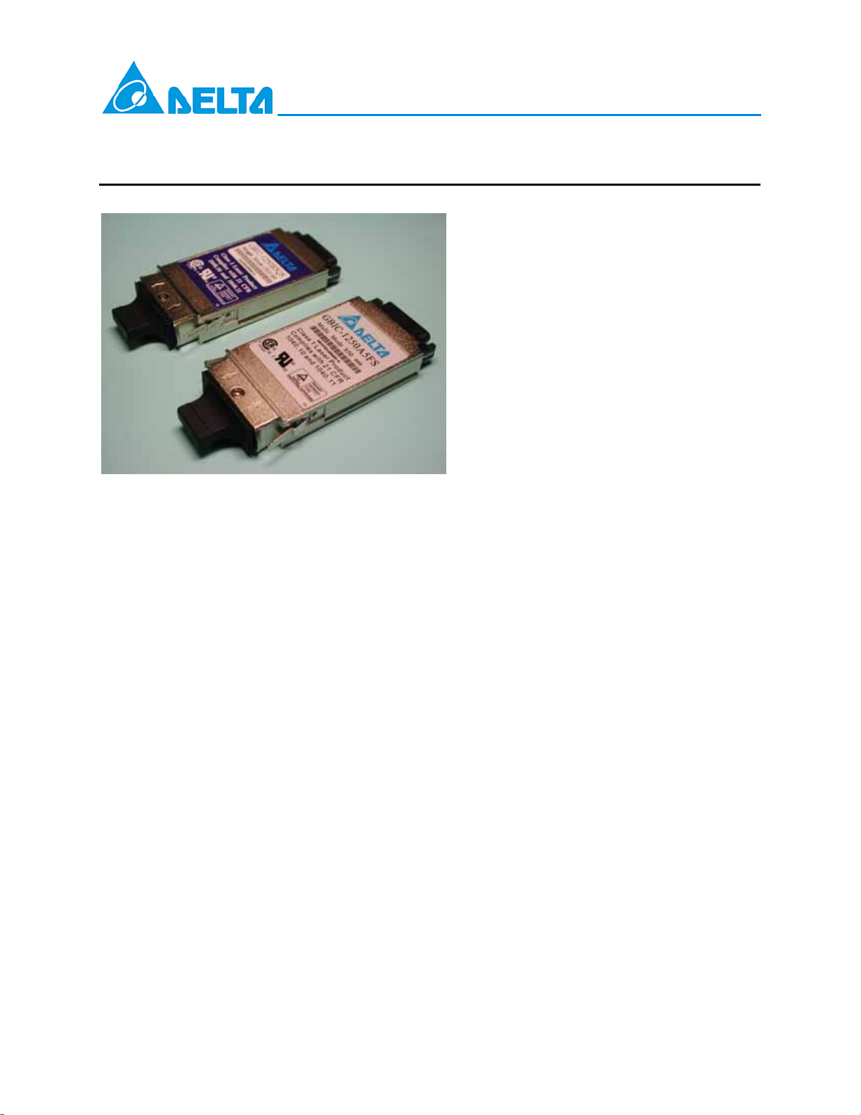
GBIC-1250 Long Distance Series
RoHS Compliant 1250Mbps Gigabit Interface Converters (GBIC)
Transceiver Module for Gigabit Ethernet
Description
The GBIC-1250xxxx families are compliant with GBIC
interface converters specification Rev. 5.4. as well as
Gigabit Ethernet standard as specified in IEEE 802.3.
Features
z Compliant with Gigabit Interface
Converter (GBIC) Revision 5.4
z Compliant with proposed specifications
for IEEE 802.3z/Gigabit Ethernet.
z Dual 5V and 3.3V Power Supply
Operation
z TTL Logic TX_DISABLE / TX_FAULT /
RX_LOS functions
z Class 1 Laser Product Compliant with
the Requirements of IEC 60825-1 and
IEC 60825-2
z Hot-Pluggable
z RoHS Compliant per Directive
2002/95/EEC
Applications
z 1.25 Gigabit Ethernet
z Fiber Channel
Delta’s GBIC transceiver family uses a 20-pin connector
to allow hot plug capability. The system designer can
make configuration changes or maintenance simply by
plugging in different type of converters without removing
the power supply from the host system.
Performance
GBIC-1250B5LR:
1310nm MQW DFB laser, up to 25km in SMF
GBIC-1250D5MR:
1550nm MQW DFB laser, up to 40km in SMF
GBIC-1250D5WR:
1550nm MQW DFB laser, up to 70km in SMF
GBIC-1250D5RR:
1550nm MQW DFB laser, up to 80km in SMF
GBIC-1250D5VR:
1550nm MQW DFB laser, up to 100km in SMF
DELTA ELECTRONICS, INC.
1 01/23/2008
Rev. 0F
www.deltaww.com
Page 2
GBIC-1250 Long Distance Series
Absolute Maximum Ratings
Parameter Symbol Min. Typ. Max. Unit Notes
Storage Temperature Ts -40 85 ºC
Supply Voltage VCC 0 6 V
Recommended Operating Conditions
Parameter Symbol Min. Typ. Max. Unit
Ambient Operating Temperature T
A
-5 70
℃
Notes
Supply voltage Vcc 3.15 / 4.75 3.3 / 5 3.45 / 5.25 V
Total Supply Current I
Data Output Load R
S
DL
300 mA
75
Ω
Transmitter Electro-Optical Performance Specifications:
(TA=-5 °C to 70 °C, VCC=3.15V to 3.45V or V
Parameter Symbol Min. Typ. Max. Unit Note
Transmitter
Transmitter Differential Input Voltage VDT 0.5 2.4 V 1
Transmitter Disable Input-High V
Transmitter Disable Input-Low V
Transmitter Fault Pull up Resistor R
Transmitter Fault Output-High V
Transmitter Fault Output-Low V
Receiver
Receiver Differential Output Voltage VDR 0.35 2 V 3
Receiver LOS Load R
LOS Output Voltage-High V
LOS Output Voltage-Low V
Output Dara Rise / Fall Time tr / t
Notes:
1. Internally AC coupled and terminated to 150Ohm differential load.
2. Pull up to V
on host Board
CC
3. Internally AC coupled, but requires a 150Ohm differential termination at or internal to Serializer/
Deserializer.
4. These are 20%~80% values.
=4.75V to 5.25V)
CC
DISH
DISL
TX_FAULT
TXFH
TXFL
RXLOS
LOSH
LOSL
f
2 VCC+0.3 V
0 0.8 V
4.7 10 kΩ 2
2 VCC+0.3 V 2
0 0.8 V 2
4.7 10 kΩ 2
2 VCC+0.3 V 2
0 0.8 V 2
220 psec 4
DELTA ELECTRONICS, INC.
2 01/23/2008
Rev. 0F
www.deltaww.com
Page 3
N
0
Normalized
GBIC-1250 Long Distance Series
Optical Characteristics
(TA=-5 °C to 70 °C, VCC=3.15V to 3.45V or VCC=4.75V to 5.25V, Data Rate=1250Mb/sec, PRBS=27-1NRZ)
Parameter Symbol Min. Typ. Max. Unit Note
Transmitter
Output Optical Power (Avg.)
GBIC-1250B5LR
GBIC-1250D5MR
GBIC-1250D5WR
P
O
GBIC-1250D5RR
GBIC-1250D5VR
Optical Extinction Ratio ER 9 dB
Center Wavelength
GBIC-1250B5 Series
λ
C
GBIC-1250D5 Series
Spectral Width
Optical Rise/ Fall Time
σ
t
r/tf
Receiver
Optical input sensitivity (avg.)
GBIC-1250B5LR
GBIC-1250D5MR
GBIC-1250D5WR
P
IN
GBIC-1250D5RR
GBIC-1250D5VR
Optical input saturation (avg.)
GBIC-1250B5 Series
GBIC-1250D5 Series
P
SAT
GBIC-1250D5VR
Optical Wavelength
λ
LOS - Deasserted (avg.)
GBIC-1250B5LR
GBIC-1250D5MR
GBIC-1250D5WR
P
A
GBIC-1250D5RR
GBIC-1250D5VR
LOS - Asserted (avg.) P
LOS - Hysteresis PA -P
D
D
Note:
1. The sensitivity is provided at a BER of 1×10
-1 PRBS and ER=9dB.
2. These are 20%~80% values
1Y3
1
1Y
0.
Y
-Y
-4
-5
-3
0
0
1274
1530
1310
1550
1
0
2
5
5
1355
1570
dBm
nm
1 nm
260 psec 2
-23
-22
-24
dBm 1
-24
-29
-1
-1
dBm
-9
1270 1570 nm
-23
-22
-24
dBm
-24
-29
-40 dBm
0.5 dB
-12
or better with an input signal consisting of 1250Mb/s, 2
1
1X
0 XX
1X
ormalized
7
DELTA ELECTRONICS, INC.
3 01/23/2008
Rev. 0F
www.deltaww.com
Page 4
GBIC-1250 Long Distance Series
Pin Out Table
Pin Name Pin# Sequence Sequence Pin# Pin Name
RX_LOS 1 2 1 11 RGND
RGND 2 2 1 12 -RX_DAT
RGND 3 2 1 13 +RX_DAT
MOD_DEF(0) 4 2 1 14 RGND
MOD_DEF(1) 5 2 2 15 VDDR
MOD_DEF(2) 6 2 2 16 VDDT
TX_DISABLE 7 2 1 17 TGND
TGND 8 2 1 18 +TX_DAT
TGND 9 2 1 19 -TX_DAT
TX_FAULT 10 2 1 20 TGND
Overview of internal interface signal Definition
Pin Name Pin # Name/Function Signal Specification
Receiver Signals
RGND 2,3,11,14 Receiver Ground (may be connected with TGND in GBIC) Ground, to GBIC
VDDR 15 Receiver +5 volt (may be connected with VDDT in GBIC) Power, to GBIC
-RX_DAT 12 Receive Data, Differential PECL
+RX_DAT 13 Receive Data, Differential PECL
RX_LOS 1
Transmitter Signals
TGND 8,9,17,20 Transmitter Ground (may be connected with RGND internally) Ground, to GBIC
VDDT 16 Transmitter +5 volt (may be connected with VDDR in GBIC) Power, to GBIC
+TX_DAT 18 Transmit Data, Differential PECL High speed serial, to GBIC
-TX_DAT 19 Transmit Data, Differential PECL High speed serial, to GBIC
TX_DISABLE 7
TX_FAULT 10
Control Signals
MOD_DEF(0) 4
MOD_DEF(1) 5
MOD_DEF(2) 6
Receiver Loss of Signal, logic high, open collector
compat-ible,4.7 K to 10 K Ohm pullup to VDDT on host
Transmitter Disable, logic high, open collector compatible,4.7
K to 10 K Ohm pullup to VDDT on GBIC
Transmitter Fault, logic high, open collector compatible,4.7 K
to 10 K Ohm pullup to VDDT on host
GBIC module definition and presence, bit 0,4.7 K to 10 K Ohm
pullup to VDDT on host
GBIC module definition and presence, bit 1,4.7 K to 10 K Ohm
pullup to VDDT on host
GBIC module definition and presence, bit 2,4.7 K to 10 K Ohm
pullup to VDDT on host
High speed serial, from
GBIC
High speed serial, from
GBIC
Low speed, from GBIC
Low speed, to GBIC
Low speed, from GBIC
Low speed, from GBIC
Low speed, from GBIC
Low speed, from GBIC
DELTA ELECTRONICS, INC.
4 01/23/2008
Rev. 0F
www.deltaww.com
Page 5
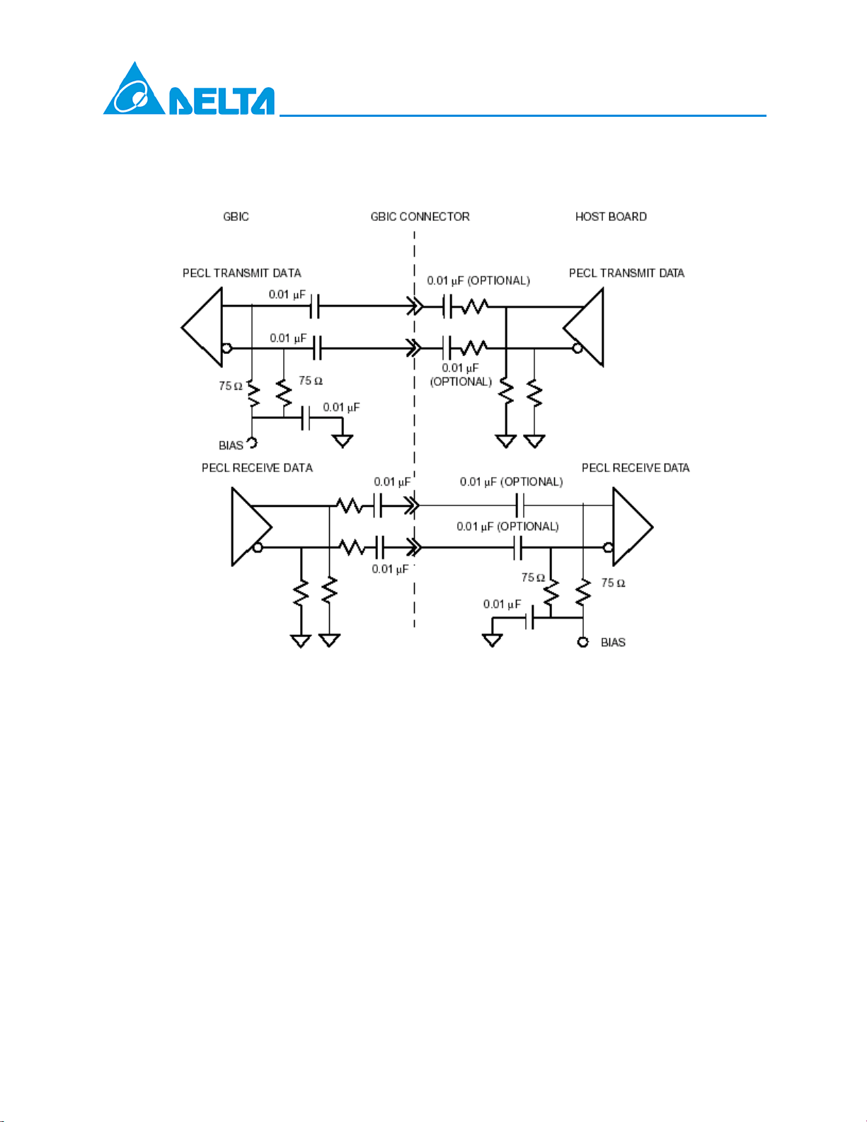
Recommend Circuit Schematic
GBIC-1250 Long Distance Series
DELTA ELECTRONICS, INC.
5 01/23/2008
Rev. 0F
www.deltaww.com
Page 6
GBIC-1250 Long Distance Series
GBIC module definition parameters
Module
Definition
MOD_DEF(0)
Pin 4
0 NC NC NC GBIC not present clause
1 NC NC TTL LOW
2 NC TTL LOW NC
3 NC TTL LOW TTL LOW Optical LW, 1.0625 Gbd 100-SM-LC-L
4 TTL LOW SCL SDA Serial module definition protocol
5 TTL LOW NC TTL LOW
6 TTL LOW TTL LOW NC
7 TTL LOW TTL LOW TTL LOW
MOD_DEF(1)
Pin 5
MOD_DEF(2)
Pin 6
Interpretation by host Reference
Copper Style 1 or Style 2 connector, 1.0625 Gbd,
100-TW-EL-S or 100-TP-EL-S, active
inter-enclosure connection and IEEE802.3
1000BASE-CX
Copper Style 1 or Style 2 connector, 1.0625 Gbd,
100-TW-EL-S, or 100-TP-EL-S, active or passive
intra-enclosure connection
Optical SW, 1.0625 Gbd 100-M5-SN-I or
100-M6-SN-I
Optical LW, 1.0625 Gbd 100-SM-LC-L and similar
to 1.25 Gbd IEEE802.3z 1000BASE-LX, single
mode
Optical SW, 1.0625 Gbd 100-M5-SN-I or
100-M6-SN-I and 1.25 Gbd, IEEE 802.3z,
1000BASE-SX
GBIC timing parameters for GBIC management
Parameter Symbol Min. Max. Unit Unit Conditions
TX_DISABLE assert time t_off 10 µsec
TX_DISABLE negate
time
Time to initialize,
includes reset of
TX_FAULT
TX_FAULT from fault to
assertion
TX_DISABLE time to
start reset
RX_LOS assert delay t_loss_on 100 µsec
RX_LOS negate delay t_loss_off 100 µsec
t_on 1 mec
t_init 300 msec
t_fault 100 µsec
t_rest 10 µsec TX_DISABLE HIGH before TX_DISABLE set LOW
Rising edge of TX_DISABLE to fall of output signal
below 10% of nominal
Falling edge of TX_DISABLE to rise of output
signal above 90% of nominal
From power on or hot plug fter V DD T > 4.75 volts
or From negation of TX_DISABLE during reset of
TX_FAULT.
From occurrence of fault (out-put safety violation or
V DD T < 4.5 volts)
From detection of loss of signal to assertion of
RX_LOS
From detection of presence of signal to negation of
RX_LOS
DELTA ELECTRONICS, INC.
6 01/23/2008
Rev. 0F
www.deltaww.com
Page 7
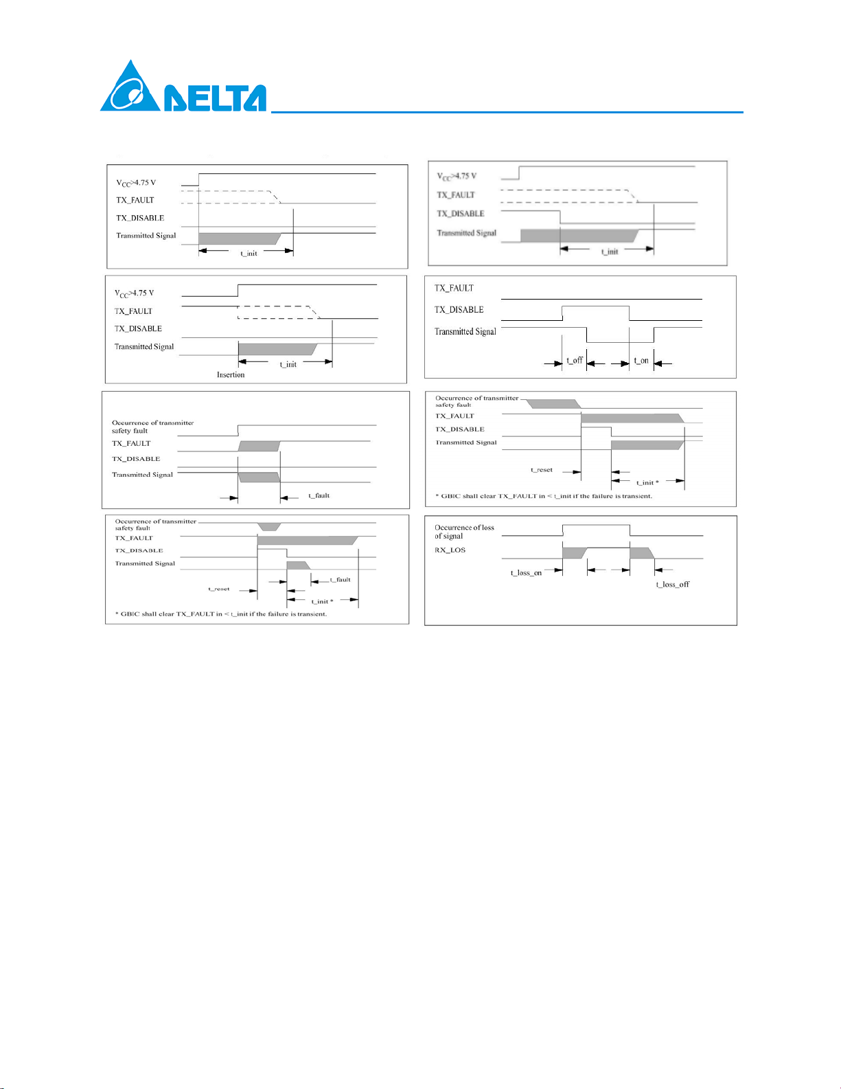
GBIC timing parameters:
GBIC-1250 Long Distance Series
DELTA ELECTRONICS, INC.
7 01/23/2008
Rev. 0F
www.deltaww.com
Page 8

GBIC-1250 Long Distance Series
GBIC-1250B5LR EEPROM Serial ID Memory Contents (2-Wire Address A0h)
Address
Hex ASCII
00 01 25 20 50 35 5 75 SN 100 00 125 00
01 04 26 20 51 4C L 76 SN 101 00 126 00
02 01 27 20 52 52 R 77 SN 102 00 127 00
03 00 28 20 53 20 78 SN 103 00
04 00 29 20 54 20 79 SN 104 00
05 00 30 20 55 20 80 SN 105 00
06 02 31 20 56 41 A 81 SN 106 00
07 80 32 20 57 20 82 SN 107 00
08 10 33 20 58 20 83 SN 108 00
09 01 34 20 59 20 84 DC Note 3 109 00
10 01 35 20 60 05 85 DC 110 00
11 01 36 00 61 1E 86 DC 111 00
12 0D 37 00 62 00 87 DC 112 00
13 00 38 00 63 C8 Note 1 88 DC 113 00
14 19 39 00 64 00 89 DC 114 00
15 FA 40 47 G 65 1A 90 DC 115 00
16 00 41 42 B 66 05 91 DC 116 00
17 00 42 49 I 67 05 92 00 117 00
18 00 43 43 C 68 SN Note 2 93 00 118 00
19 00 44 2D - 69 SN 94 00 119 00
20 44 D 45 31 1 70 SN 95 CS2 Note 4 120 00
21 45 E 46 32 2 71 SN 96 00 121 00
22 4C L 47 35 5 72 SN 97 00 122 00
23 54 T 48 30 0 73 SN 98 00 123 00
24 41 A 49 42 B 74 SN 99 00 124 00
Address
Hex ASCII
Address
Hex ASCII
Address
Hex ASCII
Address
Hex ASCII
Address
Hex ASCII
GBIC-1250D5MR EEPROM Serial ID Memory Contents (2-Wire Address A0h)
Address
Hex ASCII
00 01 25 20 50 35 5 75 SN 100 00 125 00
01 04 26 20 51 4D M 76 SN 101 00 126 00
02 01 27 20 52 52 R 77 SN 102 00 127 00
03 00 28 20 53 20 78 SN 103 00
04 00 29 20 54 20 79 SN 104 00
05 00 30 20 55 20 80 SN 105 00
06 02 31 20 56 41 A 81 SN 106 00
07 80 32 20 57 20 82 SN 107 00
08 10 33 20 58 20 83 SN 108 00
09 01 34 20 59 20 84 DC Note 3 109 00
10 01 35 20 60 06 85 DC 110 00
11 01 36 00 61 0E 86 DC 111 00
12 0D 37 00 62 00 87 DC 112 00
13 00 38 00 63 D0 Note 1 88 DC 113 00
14 28 39 00 64 00 89 DC 114 00
15 FF 40 47 G 65 1A 90 DC 115 00
16 00 41 42 B 66 05 91 DC 116 00
17 00 42 49 I 67 05 92 00 117 00
18 00 43 43 C 68 SN Note 2 93 00 118 00
19 00 44 2D - 69 SN 94 00 119 00
20 44 D 45 31 1 70 SN 95 CS2 Note 4 120 00
21 45 E 46 32 2 71 SN 96 00 121 00
22 4C L 47 35 5 72 SN 97 00 122 00
23 54 T 48 30 0 73 SN 98 00 123 00
24 41 A 49 44 D 74 SN 99 00 124 00
Notes:
1) Byte 63: Check sum of bytes 0-62.
2) Byte 68-83 (SN): Serial number.
3) Byte 84-91 (DC): Date code.
4) Byte 95 (CS2): Check sum of bytes 64-94.
Address
Hex ASCII
Address
Hex ASCII
Address
Hex ASCII
Address
Hex ASCII
Address
Hex ASCII
DELTA ELECTRONICS, INC.
8 01/23/2008
Rev. 0F
www.deltaww.com
Page 9

GBIC-1250 Long Distance Series
GBIC-1250D5WR EEPROM Serial ID Memory Contents (2-Wire Address A0h)
Address
Hex ASCII
00 01 25 20 50 35 5 75 SN 100 00 125 00
01 04 26 20 51 57 W 76 SN 101 00 126 00
02 01 27 20 52 52 R 77 SN 102 00 127 00
03 00 28 20 53 20 78 SN 103 00
04 00 29 20 54 20 79 SN 104 00
05 00 30 20 55 20 80 SN 105 00
06 02 31 20 56 41 A 81 SN 106 00
07 80 32 20 57 20 82 SN 107 00
08 10 33 20 58 20 83 SN 108 00
09 01 34 20 59 20 84 DC Note 3 109 00
10 01 35 20 60 06 85 DC 110 00
11 01 36 00 61 0E 86 DC 111 00
12 0D 37 00 62 00 87 DC 112 00
13 00 38 00 63 F8 Note 1 88 DC 113 00
14 46 39 00 64 00 89 DC 114 00
15 FF 40 47 G 65 1A 90 DC 115 00
16 00 41 42 B 66 05 91 DC 116 00
17 00 42 49 I 67 05 92 00 117 00
18 00 43 43 C 68 SN Note 2 93 00 118 00
19 00 44 2D - 69 SN 94 00 119 00
20 44 D 45 31 1 70 SN 95 CS2 Note 4 120 00
21 45 E 46 32 2 71 SN 96 00 121 00
22 4C L 47 35 5 72 SN 97 00 122 00
23 54 T 48 30 0 73 SN 98 00 123 00
24 41 A 49 44 D 74 SN 99 00 124 00
Address
Hex ASCII
Address
Hex ASCII
Address
Hex ASCII
Address
Hex ASCII
Address
Hex ASCII
GBIC-1250D5RR EEPROM Serial ID Memory Contents (2-Wire Address A0h)
Address
Hex ASCII
00 01 25 20 50 35 5 75 SN 100 00 125 00
01 04 26 20 51 52 R 76 SN 101 00 126 00
02 01 27 20 52 52 R 77 SN 102 00 127 00
03 00 28 20 53 20 78 SN 103 00
04 00 29 20 54 20 79 SN 104 00
05 00 30 20 55 20 80 SN 105 00
06 02 31 20 56 41 A 81 SN 106 00
07 80 32 20 57 20 82 SN 107 00
08 10 33 20 58 20 83 SN 108 00
09 01 34 20 59 20 84 DC Note 3 109 00
10 01 35 20 60 06 85 DC 110 00
11 01 36 00 61 0E 86 DC 111 00
12 0D 37 00 62 00 87 DC 112 00
13 00 38 00 63 FD Note 1 88 DC 113 00
14 50 39 00 64 00 89 DC 114 00
15 FF 40 47 G 65 1A 90 DC 115 00
16 00 41 42 B 66 05 91 DC 116 00
17 00 42 49 I 67 05 92 00 117 00
18 00 43 43 C 68 SN Note 2 93 00 118 00
19 00 44 2D - 69 SN 94 00 119 00
20 44 D 45 31 1 70 SN 95 CS2 Note 4 120 00
21 45 E 46 32 2 71 SN 96 00 121 00
22 4C L 47 35 5 72 SN 97 00 122 00
23 54 T 48 30 0 73 SN 98 00 123 00
24 41 A 49 44 D 74 SN 99 00 124 00
Notes:
1) Byte 63: Check sum of bytes 0-62.
2) Byte 68-83 (SN): Serial number.
3) Byte 84-91 (DC): Date code.
4) Byte 95 (CS2): Check sum of bytes 64-94.
Address
Hex ASCII
Address
Hex ASCII
Address
Hex ASCII
Address
Hex ASCII
Address
Hex ASCII
DELTA ELECTRONICS, INC.
9 01/23/2008
Rev. 0F
www.deltaww.com
Page 10

GBIC-1250 Long Distance Series
GBIC-1250D5VR EEPROM Serial ID Memory Contents (2-Wire Address A0h)
Address
Hex ASCII
00 01 25 20 50 35 5 75 SN 100 00 125 00
01 04 26 20 51 56 V 76 SN 101 00 126 00
02 01 27 20 52 52 R 77 SN 102 00 127 00
03 00 28 20 53 20 78 SN 103 00
04 00 29 20 54 20 79 SN 104 00
05 00 30 20 55 20 80 SN 105 00
06 02 31 20 56 41 A 81 SN 106 00
07 80 32 20 57 20 82 SN 107 00
08 10 33 20 58 20 83 SN 108 00
09 01 34 20 59 20 84 DC Note 3 109 00
10 01 35 20 60 06 85 DC 110 00
11 01 36 00 61 0E 86 DC 111 00
12 0D 37 00 62 00 87 DC 112 00
13 00 38 00 63 15 Note 1 88 DC 113 00
14 64 39 00 64 00 89 DC 114 00
15 FF 40 47 G 65 1A 90 DC 115 00
16 00 41 42 B 66 05 91 DC 116 00
17 00 42 49 I 67 05 92 00 117 00
18 00 43 43 C 68 SN Note 2 93 00 118 00
19 00 44 2D - 69 SN 94 00 119 00
20 44 D 45 31 1 70 SN 95 CS2 Note 4 120 00
21 45 E 46 32 2 71 SN 96 00 121 00
22 4C L 47 35 5 72 SN 97 00 122 00
23 54 T 48 30 0 73 SN 98 00 123 00
24 41 A 49 44 D 74 SN 99 00 124 00
Notes:
5) Byte 63: Check sum of bytes 0-62.
6) Byte 68-83 (SN): Serial number.
7) Byte 84-91 (DC): Date code.
8) Byte 95 (CS2): Check sum of bytes 64-94.
Address
Hex ASCII
Address
Hex ASCII
Address
Hex ASCII
Address
Hex ASCII
Address
Hex ASCII
DELTA ELECTRONICS, INC.
10 01/23/2008
Rev. 0F
www.deltaww.com
Page 11
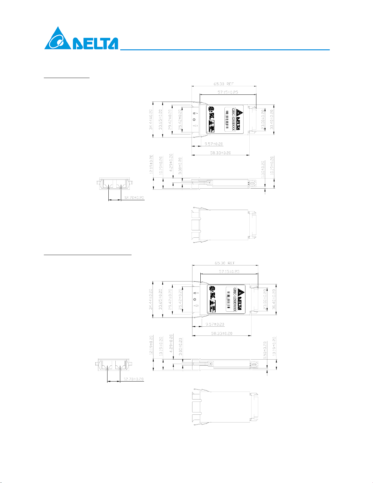
Package Outline Drawing
GBIC-1250B5LR
GBIC-1250 Long Distance Series
C
S
C
l
i
a
n
1
o
s
0
m
g
s
4
l
p
0
e
I
.
l
1
M
i
L
e
0
s
a
o
a
w
s
d
n
e
d
e
i
r
t
h
1
1
P
0
3
2
r
4
1
1
o
0
0
C
.
d
1
n
F
1
u
m
R
c
t
GBIC-1250D5 (M、W、R、V) R
C
S
C
l
i
a
n
1
o
s
0
m
g
4
s
l
p
0
e
I
.
l
1
M
i
L
e
0
s
a
o
a
w
s
d
n
e
d
e
i
t
r
h
1
1
P
0
5
2
4
r
5
1
o
0
0
C
.
d
1
n
F
1
u
m
R
c
t
DELTA ELECTRONICS, INC.
11 01/23/2008
Rev. 0F
www.deltaww.com
Page 12

Regulatory Compliance
Test Item Reference Qty’ Evaluation
(#1)
Electromagnetic Interference
EMC
FCC Class B
EN 55022 Class B
CISPR 22
GBIC-1250 Long Distance Series
5
(#2) Immunity:
Radio Frequency
Electromagnetic Field
(#3) Immunity:
Electrostatic Discharge to the
Duplex SC Receptacle
(#4) Electrostatic Discharge to
the Electrical Pins
EN 61000-4-3
IEC 1000-4-3
EN 61000-4-2
IEC 1000-4-2
IEC 801.2
MIL-STD-883C
Method 3015.4
EIAJ#1988.3.2B
Version 2,
Machine model
Ordering information for GBIC modules
GBIC-1250X1X2X3X
X1: Light source types
A: Multi-mode
B: 1310nm Single-mode
D: 1550nm Single-mode
X2: Power Supply Voltage
5: 3.3 and 5V
4
5
(1) Satisfied with electrical characteristics of
product spec.
5
(2) No physical damage
5
X3: Distance:
L: 25km
M: 10km
W: 70km
R: 80km
V: 100km
X4: R: RoHS Compliant
Others: customized parts
Available Products
z GBIC-1250A5FR: Dual supply voltage (3.3/5V), 850nm VCSEL, 50um MMF 500m.
z GBIC-1250B5QR: Dual supply voltage (3.3/5V), 1310nm MQW FP LD, SMF 10km.
12 01/23/2008
DELTA ELECTRONICS, INC.
www.deltaww.com
Rev. 0F
 Loading...