

Page 1
Page 2

Preface
Thank you very much for purchasing DELTA’s AC servo products.
This manual will be helpful in the installation, wiring, inspection, and operation of Delta AC servo drive and
motor. Before using the product, please read this user manual to ensure correct use.
You should thoroughly understand all safety precautions (DANGERS, WARNINGS and STOPS) before
proceeding with the installation, wiring and operation. If you do not understand please contact your local
Delta sales representative. Place this user manual in a safe location for future reference.
Using This Manual
Contents of this manual
This manual is a user guide that provides the information on how to install, operate and maintain
ASDA-B series AC servo drives and ECMA series AC servo motors. The contents of this manual
are including the following topics:
z Installation of AC servo drives and motors
z Configuration and wiring
z Trial run steps
z Control functions and adjusting methods of AC servo drives
z Parameter settings
z Communication protocol
z Inspection and maintenance
z Troubleshooting
z Application examples
Who should use this manual
This user manual is intended for the following users:
z Those who are responsible for designing.
z Those who are responsible for installing or wiring.
z Those who are responsible for operating or programming.
z Those who are responsible for maintaining or troubleshooting.
Important precautions
Before using the product, please read this user manual thoroughly to ensure correct use and store
this manual in a safe and handy place for quick reference whenever necessary. Besides, please
observe the following precautions:
z Do not use the product in a potentially explosive environment.
z Install the product in a clean and dry location free from corrosive and inflammable gases or
liquids.
Revision January, 2009 i
Page 3

Preface|ASDA-B Series
z Do not connect a commercial power supply to the U, V, W terminals of motor. Failure to
observe this precaution will damage either the Servo motor or drive.
z Ensure that the motor and drive are correctly connected to a ground. The grounding method
must comply with the electrical standard of the country (Please refer to NFPA 70: National
Electrical Code, 2005 Ed.).
z Do not disconnect the AC servo drive and motor while the power is ON.
z Do not attach, modify and remove wiring when power is applied to the AC servo drive and
motor.
z Before starting the operation with a mechanical system connected, make sure the
emergency stop equipment can be energized and work at any time.
z Do not touch the drive heat sink or the servo motor during operation. Otherwise, it may result
in serious personnel injury.
PLEASE READ PRIOR TO INSTALLATION FOR SAFETY.
ASDA-B series drives are open type servo drives and must be installed in an NEMA enclosure such as a
protection control panel during operation to comply with the requirements of the international safety
standards. They are provided with precise feedback control and high-speed calculation function
incorporating DSP (Digital Signal Processor) technology, and intended to drive three-phase permanent
magnet synchronous motors (PMSM) to achieve precise positioning by means of accurate current output
generated by IGBT (Insulated Gate Bipolar Transistor).
ASDA-B series drives can be used in industrial applications and for installation in an end-use enclosure that
do not exceed the specifications defined in the ASDA-B series user manual (Drives, cables and motors are
for use in a suitable enclosure with a minimum of a UL50 type 1 or NEMA 250 Type 1 rating).
Carefully notice and observe the following safety precautions when receiving, inspecting, installing, operating,
maintaining and troubleshooting. The following words, DANGER, WARNING and STOP are used to mark
safety precautions when using the Delta’s servo product. Failure to observe these precautions may void the
warranty!
The words, DANGER, WARNING and STOP, have the following meaning:
Indicates a potentially hazardous situation and if not avoided, may result in serious injury or
death.
Indicates a potentially hazardous situation and if not avoided, may result in minor to moderate
injury or serious damage to the product.
Indicates an improper action that it is not recommended to do and if doing it may cause
damage, malfunction and inability.
ii
Revision January, 2009
Page 4
Unpacking Check
¾ Please ensure that both the servo drive and motor are correctly matched for size (power rating). Failure to
observe this precaution may cause fire, seriously damage the drive / motor or cause personal injury.
Installation
¾ Do not install the product in a location that is outside the stated specification for the drive and motor. Failure to
observe this caution may result in electric shock, fire, or personal injury.
Wiring
¾ Connect the ground terminals to a class-3 ground (Ground resistance should not exceed 100Ω). Improper
grounding may result in electric shock or fire.
¾ Do not connect any power supplies to the U, V, W terminals. Failure to observe this precaution may result in
serious injury, damage to the drive or fire.
¾ Ensure that all screws, connectors and wire terminations are secure on the power supply, servo drive and motor.
Failure to observe this caution may result in damage, fire or personal injury.
Operation
¾ Before starting the operation with a mechanical system connected, change the drive parameters to match the user-
defined parameters of the mechanical system. Starting the operation without matching the correct parameters may
result in servo drive or motor damage, or damage to the mechanical system.
¾ Ensure that the emergency stop equipment or device is connected and working correctly before operating the
motor that is connected to a mechanical system.
Preface|ASDA-B Series
¾ Do not approach or touch any rotating parts (e.g. shaft) while the motor is running. Failure to observe this
precaution may cause serious personal injury.
¾ In order to prevent accidents, the initial trial run for servo motor should be conducted under no load conditions
(separate the motor from its couplings and belts).
¾ For the initial trial run, do not operate the servo motor while it is connected to its mechanical system. Connecting
the motor to its mechanical system may cause damage or result in personal injury during the trail run. Connect the
servo motor once it has successfully completed a trail run.
¾ Caution: Please perform trial run without load first and then perform trial run with load connected. After the
servo motor is running normally and regularly without load, then run servo motor with load connected. Ensure to
perform trial run in this order to prevent unnecessary danger.
¾ Do not touch either the drive heat sink or the motor during operation as they may become hot and personal injury
may result.
Maintenance and Inspection
¾ Do not touch any internal or exposed parts of servo drive and servo motor as electrical shock may result.
¾ Do not remove the operation panel while the drive is connected to an electrical power source otherwise electrical
shock may result.
¾ Wait at least 10 minutes after power has been removed before touching any drive or motor terminals or
performing any wiring and/or inspection as an electrical charge may still remain in the servo drive and servo
motor with hazardous voltages even after power has been removed.
¾ Do not disassemble the servo drive or motor as electric shock may result.
¾ Do not connect or disconnect wires or connectors while power is applied to the drive and motor.
¾ Only qualified personnel who have electrical knowledge should conduct maintenance and inspection.
Main Circuit Wiring
¾ Install the encoder cables in a separate conduit from the motor power cables to avoid signal noise. Separate the
conduits by 30cm (11.8inches) above.
¾ Use multi-stranded twisted-pair wires or multi-core shielded-pair wires for signal, encoder (PG) feedback cables.
The maximum length of command input cable is 3m (9.84ft.) and the maximum length of encoder (PG) feedback
cables is 20m (65.62ft.).
¾ As a charge may still remain in the drive with hazardous voltages even after power has been removed, be sure to
wait at least 10 minutes after power has been removed before performing any wiring and/or inspection.
Revision January, 2009 iii
Page 5
Preface|ASDA-B Series
¾ It is not recommended to frequently power the drive on and off. Do not turn the drive off and on more than once
per minute as high charging currents within the internal capacitors may cause damage.
Main Circuit Terminal Wiring
¾ Insert only one wire into one terminal on the terminal block.
¾ When inserting wires, please ensure that the conductors are not shorted to adjacent terminals or wires.
¾ Please use Y-type terminals to tighten the ends of wires.
¾ Ensure to double check the wiring before applying power to the drive.
NOTE
1) In this manual, actual measured values are in metric units. Dimensions in (imperial
units) are for reference only. Please use metric for precise measurements.
2) The content of this manual may be revised without prior notice. Please consult our
distributors or download the most updated version at
http://www.delta.com.tw/industrialautomation
.
iv
Revision January, 2009
Page 6

Table of Contents
Chapter 1 Unpacking Check and Model Explanation............................................................. 1-1
1.1 Unpacking Check ........................................................................................................................ 1-1
1.2 Model Explanation ....................................................................................................................... 1-3
1.2.1 Nameplate Information .....................................................................................................1-3
1.2.2 Model Name Explanation ................................................................................................. 1-4
1.3 Servo Drive and Servo Motor Combinations............................................................................... 1-6
1.4 Servo Drive Features................................................................................................................... 1-7
1.5 Control Modes of Servo Drive ..................................................................................................... 1-8
Chapter 2 Installation and Storage......................................................................................... 2-1
2.1 Installation Notes ......................................................................................................................... 2-1
2.2 Storage Conditions ...................................................................................................................... 2-1
2.3 Installation Conditions ................................................................................................................. 2-2
2.4 Installation Procedure and Minimum Clearances........................................................................ 2-3
Chapter 3 Connections and Wiring ........................................................................................ 3-1
3.1 Connections................................................................................................................................. 3-1
3.1.1 Connecting to Peripheral Devices .................................................................................... 3-1
3.1.2 Servo Drive Connectors and Terminals ........................................................................... 3-2
3.1.3 Wiring Methods................................................................................................................. 3-4
3.1.4 Motor Power Cable Connector Specifications.................................................................. 3-5
3.1.5 Encoder Connector Specifications ................................................................................... 3-7
3.1.6 Cable Specifications for Servo Drive and Servo Motor .................................................... 3-8
Revision January, 2009
Page 7

Table of Contents|ASDA-B Series
3.2 Basic Wiring................................................................................................................................. 3-9
3.3 Input / Output Interface Connector -CN1..................................................................................... 3-12
3.3.1 CN1 Terminal Identification .............................................................................................. 3-12
3.3.2 Signals Explanation of Connector CN1 ............................................................................ 3-13
3.3.3 User-defined DI and DO signals....................................................................................... 3-18
3.3.4 Wiring Diagrams of I/O Signals (CN1).............................................................................. 3-20
3.4 Encoder Connector CN2 ............................................................................................................. 3-24
3.5 Serial Communication Connector CN3 ....................................................................................... 3-25
3.5.1 CN3 Terminal Layout and Identification ........................................................................... 3-25
3.5.2 Connection between PC/Keypad and Connector CN3 .................................................... 3-26
3.6 Standard Connection Example.................................................................................................... 3-27
3.6.1 Position Control Mode ...................................................................................................... 3-27
3.6.2 Speed Control Mode......................................................................................................... 3-28
3.6.3 Torque Control Mode........................................................................................................ 3-29
Chapter 4 Display and Operation........................................................................................... 4-1
4.1 ASD-PU-01A ............................................................................................................................... 4-1
4.1.1 Description of Digital Keypad ASD-PU-01A..................................................................... 4-1
4.1.2 Display Flowchart ............................................................................................................. 4-3
4.1.3 Status Display................................................................................................................... 4-8
4.1.4 Fault Code Display Operation .......................................................................................... 4-11
4.1.5 JOG Operation.................................................................................................................. 4-12
4.1.6 DO Force Output Diagnosis Operation ............................................................................ 4-14
4.1.7 DI Diagnosis Operation .................................................................................................... 4-15
4.1.8 DO Diagnosis Operation................................................................................................... 4-15
4.1.9 Parameters Read and Write ............................................................................................. 4-16
Revision January, 2009
Page 8

Table of Contents|ASDA-B Series
4.2 ASD-PU-01B ............................................................................................................................... 4-18
4.2.1 Description of Digital Keypad ASD-PU-01B..................................................................... 4-18
4.2.2 Display Flowchart ............................................................................................................. 4-19
4.2.3 Status Display................................................................................................................... 4-28
4.2.4 Fault Code Display Operation .......................................................................................... 4-31
4.2.5 JOG Operation.................................................................................................................. 4-31
4.2.6 DO Force Output Diagnosis Operation ............................................................................ 4-33
4.2.7 DI Diagnosis Operation .................................................................................................... 4-34
4.2.8 DO Diagnosis Operation................................................................................................... 4-35
4.2.9 Parameters Read and Write ............................................................................................. 4-36
Chapter 5 Trial Run and Tuning Procedure ........................................................................... 5-1
5.1 Inspection without Load............................................................................................................... 5-1
5.2 Applying Power to the Drive ........................................................................................................ 5-3
5.3 JOG Trial Run without Load........................................................................................................ 5-7
5.3.1 ASD-PU-01A Tuning Flowchart........................................................................................ 5-7
5.3.2 ASD-PU-01B Tuning Flowchart........................................................................................ 5-8
5.4 Speed Trial Run without Load..................................................................................................... 5-9
5.5 Tuning Procedure ........................................................................................................................ 5-11
5.5.1 Tuning Flowchart .............................................................................................................. 5-13
5.5.2 Load Inertia Estimation Flowchart .................................................................................... 5-14
5.5.3 AutoMode (PI) Tuning Flowchart...................................................................................... 5-15
5.5.4 AutoMode (PDFF) Tuning Flowchart................................................................................ 5-17
5.5.5 Limit of Load Inertia Estimation ........................................................................................ 5-18
5.5.6 Relationship between Tuning Modes and Parameters .................................................... 5-19
5.5.7 Gain Adjustment in Manual Mode .................................................................................... 5-20
Revision January, 2009
Page 9

Table of Contents|ASDA-B Series
Chapter 6 Control Modes of Operation .................................................................................. 6-1
6.1 Control Modes of Operation ........................................................................................................ 6-1
6.2 Position Control Mode ................................................................................................................. 6-2
6.2.1 Command Source of Position Control Mode .................................................................... 6-2
6.2.2 Structure of Position Control Mode .................................................................................. 6-3
6.2.3 Pulse Inhibit Input Function (INHIBIT).............................................................................. 6-4
6.2.4 Electronic Gear Ratio ....................................................................................................... 6-4
6.2.5 Low-pass Filter ................................................................................................................. 6-6
6.2.6 Position Loop Gain Adjustment ........................................................................................ 6-6
6.3 Speed Control Mode.................................................................................................................... 6-9
6.3.1 Command Source of Speed Control Mode ...................................................................... 6-9
6.3.2 Structure of Speed Control Mode..................................................................................... 6-10
6.3.3 Smoothing Strategy of Speed Control Mode.................................................................... 6-11
6.3.4 Analog Speed Input Scaling ............................................................................................. 6-14
6.3.5 Timing Chart of Speed Control Mode............................................................................... 6-15
6.3.6 Speed Loop Gain Adjustment........................................................................................... 6-15
6.3.7 Resonance Suppression .................................................................................................. 6-23
6.4 Torque Control Mode................................................................................................................... 6-25
6.4.1 Command Source of Torque Control Mode ..................................................................... 6-25
6.4.2 Structure of Torque Control Mode.................................................................................... 6-26
6.4.3 Smoothing Strategy of Torque Control Mode................................................................... 6-27
6.4.4 Analog Torque Input Scaling ............................................................................................ 6-27
6.4.5 Timing Chart of Speed Control Mode............................................................................... 6-28
6.5 Control Modes Selection ............................................................................................................. 6-29
6.5.1 Speed / Position Control Mode Selection......................................................................... 6-29
Revision January, 2009
Page 10

Table of Contents|ASDA-B Series
6.5.2 Speed / Torque Control Mode Selection .......................................................................... 6-30
6.5.3 Torque / Position Control Mode Selection........................................................................ 6-30
6.6 Others.......................................................................................................................................... 6-31
6.6.1 Speed Limit....................................................................................................................... 6-31
6.6.2 Torque Limit...................................................................................................................... 6-31
6.6.3 Regenerative Resistor ...................................................................................................... 6-32
6.6.4 Electromagnetic Brake ..................................................................................................... 6-36
Chapter 7 Servo Parameters ................................................................................................. 7-1
7.1 Definition...................................................................................................................................... 7-1
7.2 Parameter Summary ................................................................................................................... 7-2
7.2.1 Parameters List by Group................................................................................................. 7-2
7.2.2 Parameters List by Function............................................................................................. 7-10
7.3 Detailed Parameter Listings ........................................................................................................ 7-19
Chapter 8 MODBUS Communications................................................................................... 8-1
8.1 Communication Hardware Interface............................................................................................8-1
8.2 Communication Parameter Settings............................................................................................8-4
8.3 MODBUS Communication Protocol ............................................................................................ 8-8
Chapter 9 Maintenance and Inspection ................................................................................. 9-1
9.1 Basic Inspection .......................................................................................................................... 9-1
9.2 Maintenance ................................................................................................................................ 9-2
9.3 Life of Replacement Components............................................................................................... 9-2
Chapter 10 Troubleshooting..................................................................................................... 10-1
10.1 Fault Messages Table ................................................................................................................. 10-1
10.2 Potential Cause and Corrective Actions ...................................................................................... 10-3
10.3 Clearing Faults ............................................................................................................................ 10-12
Revision January, 2009
Page 11

Table of Contents|ASDA-B Series
Chapter 11 Specifications ........................................................................................................ 11-1
11.1 Specifications of Servo Drive (ASDA-B Series) .......................................................................... 11-1
11.2 Specifications of Servo Motor (ECMA Series) ............................................................................ 11-4
11.3 Dimensions of Servo Drive.......................................................................................................... 11-7
11.4 Servo Motor Speed-Torque Curves (T-N Curve) ........................................................................ 11-10
11.5 Overload Characteristics ............................................................................................................. 11-11
11.6 Dimensions of Servo Motor ......................................................................................................... 11-18
11.7 EMI Filters Selection.................................................................................................................... 11-22
Chapter 12 Application Examples ............................................................................................ 12-1
12.1 Connecting to DVP-EH PLC and DOP-A HMI ............................................................................ 12-1
12.2 Connecting to DVP-EH PLC and Delta TP04 Series .................................................................. 12-12
12.3 External Controller Connection Examples................................................................................... 12-15
Appendix A Accessories ........................................................................................................... A-1
Revision January, 2009
Page 12

Table of Contents|ASDA-B Series
About this Manual…
User Information
Be sure to store this manual in a safe place.
Due to constantly growing product range, technical improvement and alteration or changed texts, figures and
diagrams, we reserve the right of this manual contained information change without prior notice.
Coping or reproducing any part of this manual, without written consent of Delta Electronics Inc. is prohibited.
Technical Support and Service
Welcome to contact us or visit our web site (http://www.delta.com.tw/industrialautomation/) if you need any
technical support, service and information, or, if you have any question in using the product. We are looking
forward to serve you needs and willing to offer our best support and service to you. Reach us by the
following ways.
ASIA
DELTA ELECTRONICS, INC.
Taoyuan Plant 1
31-1, XINGBANG ROAD,
GUISHAN INDUSTRIAL ZONE,
TAOYUAN COUNTY 33370, TAIWAN, R.O.C.
TEL: 886-3-362-6301
FAX: 886-3-362-7267
NORTH/SOUTH AMERICA
DELTA PRODUCTS CORPORATION (USA)
Raleigh Office
P.O. BOX 12173
5101 DAVIS DRIVE,
RESEARCH TRIANGLE PARK, NC 27709, U.S.A.
TEL: 1-919-767-3813
FAX: 1-919-767-3969
JAPAN
DELTA ELECTRONICS (JAPAN), INC.
Tokyo Office
DELTA SHIBADAIMON BUILDING
2-1-14 SHIBADAIMON, MINATO-KU,
TOKYO, 105-0012, JAPAN
TEL: 81-3-5733-1111
FAX: 81-3-5733-1211
EUROPE
DELTRONICS (THE NETHERLANDS) B.V.
Eindhoven Office
DE WITBOGT 15, 5652 AG EINDHOVEN,
THE NETHERLANDS
TEL: 31-40-259-2850
FAX: 31-40-259-2851
Revision January, 2009
Page 13

Table of Contents|ASDA-B Series
This page intentionally left blank
Revision January, 2009
Page 14

Chapter 1 Unpacking Check and Model Explanation
1.1 Unpacking Check
After receiving the AC servo drive, please check for the following:
Ensure that the product is what you have ordered.
Verify the part number indicated on the nameplate corresponds with the part number of your order
(Please refer to Section 1.2 for details about the model explanation).
Ensure that the servo motor shaft rotates freely.
Rotate the motor shaft by hand; a smooth rotation will indicate a good motor. However, a servo motor
with an electromagnetic brake can not be rotated manually.
Check for damage.
Inspect the unit to insure it was not damaged during shipment.
Check for loose screws.
Ensure that all necessary screws are tight and secure.
If any items are damaged or incorrect, please inform the distributor whom you purchased the product from or
your local Delta sales representative.
A complete and workable AC servo system should be including the following parts:
Part I : Delta standard supplied parts
(1) Servo drive
(2) Servo motor
(3) Quick Start
Part II : Optional parts, not Delta standard supplied part (Refer to Appendix A)
(1) One power cable, which is used to connect servo motor and U, V, W terminals of servo drive. This
power cable is with one green grounding cable. Please connect the green grounding cable to the
ground terminal of the servo drive.
(2) One encoder cable, which is used to connect the encoder of servo motor and CN2 terminal of servo
drive.
(3) CN1 Connector: 25 PIN Connector (D-sub Connector)
(4) CN2 Connector: 9 PIN Connector (D-sub Connector)
(5) CN3 Connector: 8 PIN Connector (DIN Cable Mount Male)
Revision January 2009 1-1
Page 15
Chapter 1 Unpacking Check and Model Explanation|ASDA-B Series
Delta AC Servo Drive and Motor
1-2 Revision January 2009
Page 16
1.2 Model Explanation
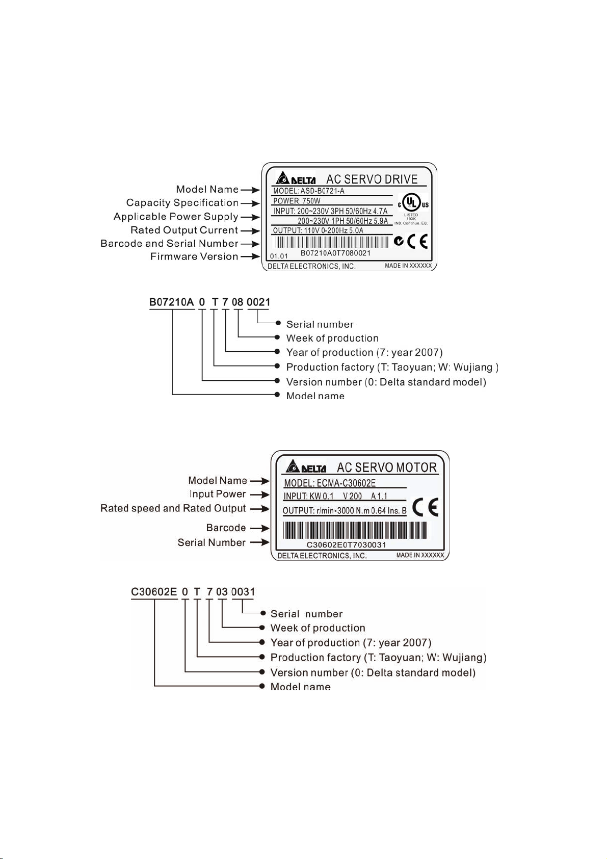
1.2.1 Nameplate Information
ASDA-B Series Servo Drive
Nameplate Explanation
Serial Number Explanation
Chapter 1 Unpacking Check and Model Explanation|ASDA-B Series
ECMA Series Servo Motor
Nameplate Explanation
Serial Number Explanation
Revision January 2009 1-3
Page 17
Chapter 1 Unpacking Check and Model Explanation|ASDA-B Series
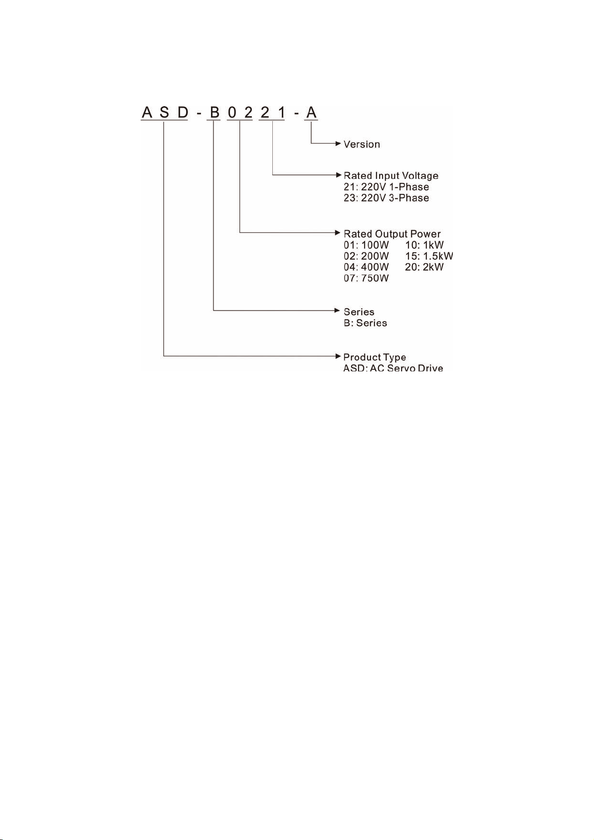
1.2.2 Model Name Explanation
ASDA-B Series Servo Drive
1-4 Revision January 2009
Page 18
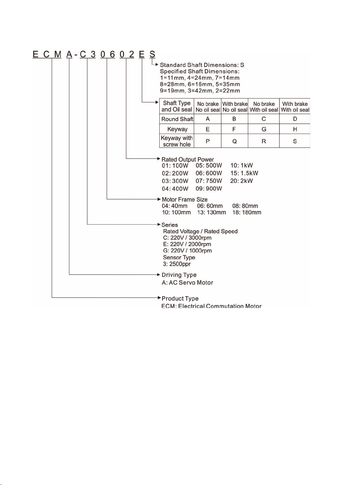
ECMA Series Servo Motor
Chapter 1 Unpacking Check and Model Explanation|ASDA-B Series
Revision January 2009 1-5
Page 19

Chapter 1 Unpacking Check and Model Explanation|ASDA-B Series
1.3 Servo Drive and Servo Motor Combinations
The table below shows the possible combination of Delta ASDA-B series servo drives and ECMA series
servo motors. The boxes () in the model names are for optional configurations. (Please refer to Section 1.2
for model explanation)
Servo Drive Servo Motor
100W ASD-B0121-A
200W ASD-B0221-A
400W ASD-B0421-A
750W ASD-B0721-A
1000W ASD-B1021-A
1500W ASD-B1521-A
2000W ASD-B2023-A
ECMA-C30401S (S=8mm)
ECMA-C30602S (S=14mm)
ECMA-C30604S (S=14mm)
ECMA-C308047 (7=14mm)
ECMA-E31305S (S=22mm)
ECMA-G31303S (S=22mm)
ECMA-C30807S (S=19mm)
ECMA-G31306S (S=22mm)
ECMA-C31010S (S=22mm)
ECMA-E31310S (S=22mm)
ECMA-G31309S (S=22mm)
ECMA-E31315S (S=22mm)
ECMA-C31020S (S=22mm)
ECMA-E31320S (S=22mm)
ECMA-E31820S (S=35mm)
The drives shown in the above table are designed for use in combination with the specific servo motors.
Check the specifications of the drives and motors you want to use.
Also, please ensure that both the servo drive and motor are correctly matched for size (power rating). If the
power of motor and drive is not within the specifications, the drive and motor may overheat and servo alarm
would be activated. For the detail specifications of servo drives and motors, please refer to Chapter 11
“Specifications”.
The drives shown in the above table are designed according to the three multiple of rated current of motors
shown in the above table. If the drives which are designed according to the six multiple of rated current of
motors are needed, please contact our distributors or your local Delta sales representative.
1-6 Revision January 2009
Page 20
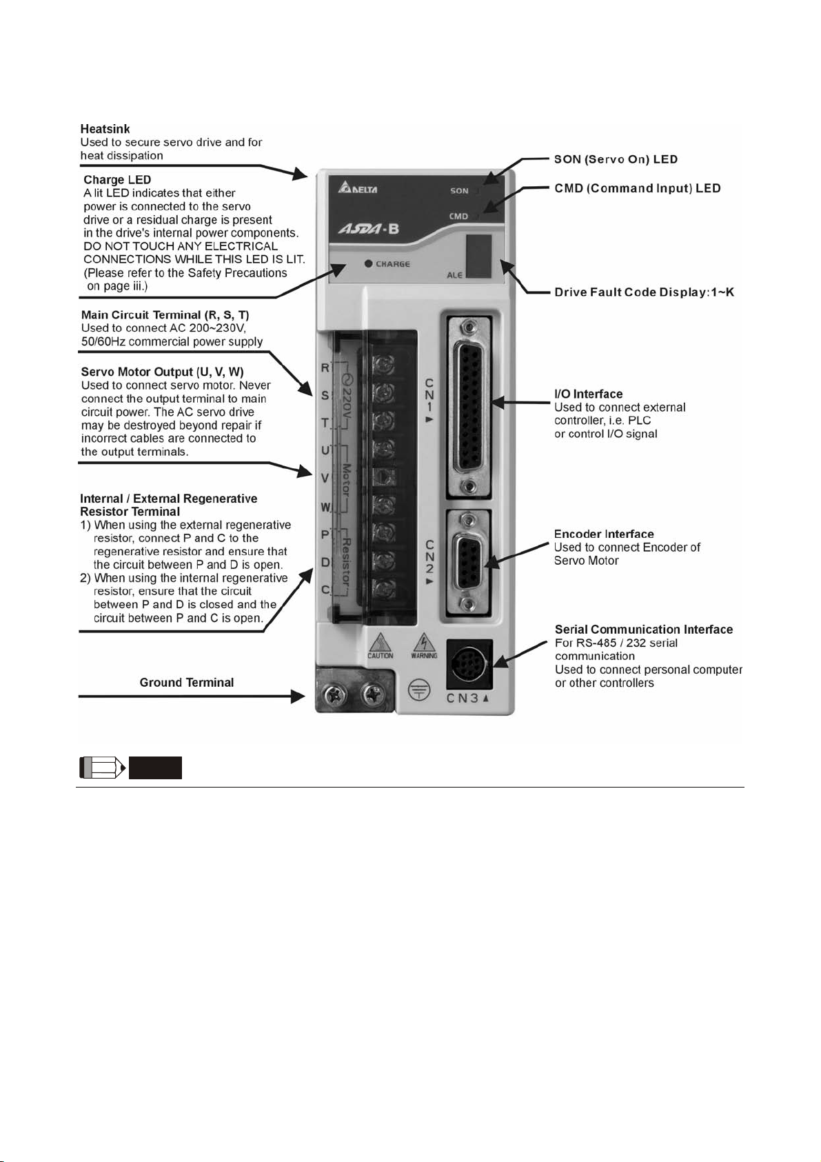
1.4 Servo Drive Features
Chapter 1 Unpacking Check and Model Explanation|ASDA-B Series
NOTE
1) Only 750W and above servo drives are provided with built-in regenerative resistors. The servo drives
below 400W are not.
2) CMD LED: A lit CMD LED indicates that the servo drive is ON (Servo On) or the motor speed is equal to
or higher than the setting value of P1-38 (>=P1-38 (ZSPD)).
Revision January 2009 1-7
Page 21

Chapter 1 Unpacking Check and Model Explanation|ASDA-B Series
1.5 Control Modes of Servo Drive
The Delta Servo can be programmed to provide five single and three dual modes of operation.
Their operation and description is listed in the following table.
Mode Code Description
Single
Mode
External Position Control P
Speed Control S
Internal Speed Control Sz
Torque Control T
Internal Torque Control Tz
S-P
Position control for the servo motor is achieved via an
external pulse command.
Speed control for the servo motor can be achieved via
parameters set within the servo drive or from an external
analog -10 ~ +10 Vdc command. Control of the internal
speed parameters is via the Digital Inputs (DI). (A
maximum of three speeds can be stored internally).
Speed control for the servo motor is only achieved via
parameters set within the servo drive. Control of the
internal speed parameters is via the Digital Inputs (DI). (A
maximum of three speeds can be stored internally).
Torque control for the servo motor can be achieved via
parameters set within the servo drive or from an external
analog -10 ~ +10 Vdc command. Control of the internal
torque parameters is via the Digital Inputs (DI). (A
maximum of three torque levels can be stored internally).
Torque control for the servo motor is only achieved via
parameters set within the servo drive. Control of the
internal torque parameters is via the Digital Inputs (DI). (A
maximum of three torque levels can be stored internally).
Either S or P control mode can be selected via the Digital
Inputs (DI). (Please refer to Chapter 7 for more detailed DI
setting.)
Either T or P control mode can be selected via the Digital
Dual Mode
The above control modes can be accessed and changed via by parameter P1-01. If the control mode is
changed, switch the drive off and on after the new control mode has been entered. The new control mode
will only be valid after drive off/on action. Please see safety precautions on page iii (switching drive off/on
multiple times).
T-P
S-T
Inputs (DI). (Please refer to Chapter 7 for more detailed DI
setting.)
Either S or T control mode can be selected via the Digital
Inputs (DI). (Please refer to Chapter 7 for more detailed DI
setting.)
1-8 Revision January 2009
Page 22

Chapter 2 Installation and Storage
2.1 Installation Notes
Pay close attention on the following installation notes:
Do not bend or strain the connection cables between servo drive and motor.
When mounting servo drive, make sure to tighten screws to secure the drive in place.
If the servo motor shaft is coupled directly to a rotating device ensure that the alignment specifications of
the servo motor, coupling, and device are followed. Failure to do so may cause unnecessary loads or
premature failure to the servo motor.
If the length of cable connected between servo drive and motor is more than 20m (65.62ft.), please
increase the wire gauge of the encoder cable and motor connection cable (connected to U, V, W
terminals).
Make sure to tighten the screws for securing motor.
2.2 Storage Conditions
The product should be kept in the shipping carton before installation. In order to retain the warranty coverage,
the AC servo drive should be stored properly when it is not to be used for an extended period of time. Some
storage suggestions are:
Store in a clean and dry location free from direct sunlight.
Store within an ambient temperature range of -20°C to +65°C (-4°F to 149°F).
Store within a relative humidity range of 0% to 90% and non-condensing.
Do not store in a place subjected to corrosive gases and liquids.
Correctly packaged and placed on a solid surface.
Revision January 2009 2-1
Page 23

Chapter 2 Installation and Storage|ASDA-B Series
2.3 Installation Conditions
Operating Temperature
ASDA-B Series Servo Drive : 0°C to 45°C (32°F to 113°F)
ECMA Series Servo Motor : 0°C to 40°C (32°F to 104°F)
The ambient temperature of servo drive for long-term reliability should be under 45°C (113°F).
If the ambient temperature of servo drive is greater than 45°C (113°F), please install the drive in a well-
ventilated location and do not obstruct the airflow for the cooling fan.
Caution
The servo drive and motor will generate heat. If they are installed in a control panel, please ensure sufficient
space around the units for heat dissipation.
Pay particular attention to vibration of the units and check if the vibration has impacted the electric devices in
the control panel. Please observe the following precautions when selecting a mounting location. Failure to
observe the following precautions may void the warranty!
Do not mount the servo drive or motor adjacent to heat-radiating elements or in direct sunlight.
Do not mount the servo drive or motor in a location subjected to corrosive gases, liquids, or airborne
dust or metallic particles.
Do not mount the servo drive or motor in a location where temperatures and humidity will exceed
specification.
Do not mount the servo drive or motor in a location where vibration and shock will exceed specification.
Do not mount the servo drive or motor in a location where it will be subjected to high levels of
electromagnetic radiation.
2-2 Revision January 2009
Page 24
Chapter 2 Installation and Storage|ASDA-B Series
2.4 Installation Procedure and Minimum Clearances
Installation Procedure
Incorrect installation may result in a drive malfunction or premature failure of the drive and or motor. Please
follow the guidelines in this manual when installing the servo drive and motor.
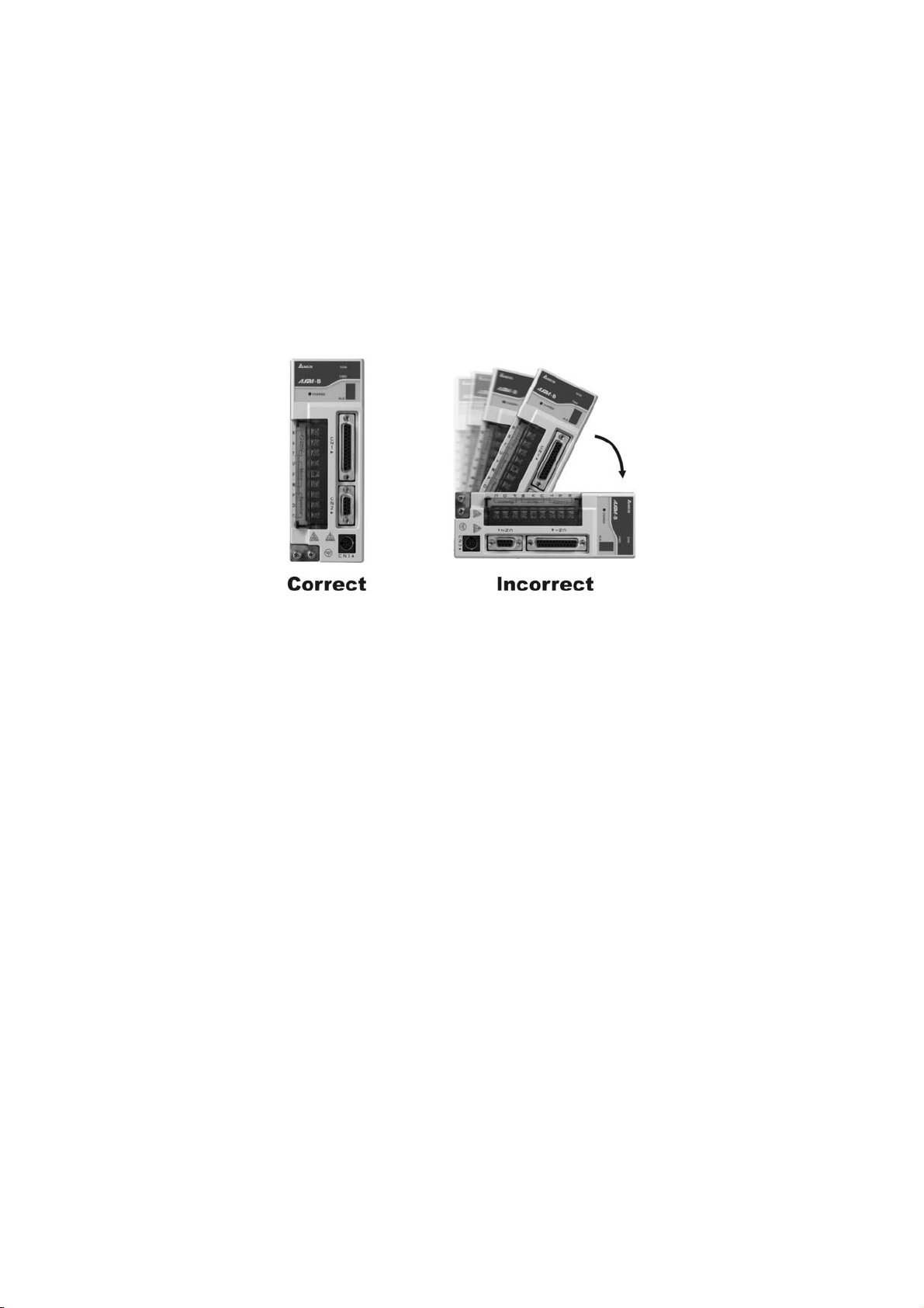
The ASDA-B servo drive should be mounted perpendicular to the wall or in the control panel. In order to
ensure the drive is well ventilated, ensure that the all ventilation holes are not obstructed and sufficient free
space is given to the servo drive. Do not install the drive in a horizontal position or malfunction and damage
will occur.
Drive Mounting
The ASDA-B Servo drives must be back mounted vertically on a dry and solid surface such as a NEMA
enclosure. A minimum spacing of two inches must be maintained above and below the drive for ventilation
and heat dissipation. Additional space may be necessary for wiring and cable connections. Also, as the drive
conducts heat away via the mounting, the mounting plane or surface should be conductor away and not
conduct heat into the drive from external sources
Motor Mounting
The ECMA Servo motors should be mounted firmly to a dry and solid mounting surface to ensure maximum
heat transfer for maximum power output and to provide a good ground.
For the dimensions and weights specifications of servo drive or motor, please refer to Chapter 11
“Specifications".
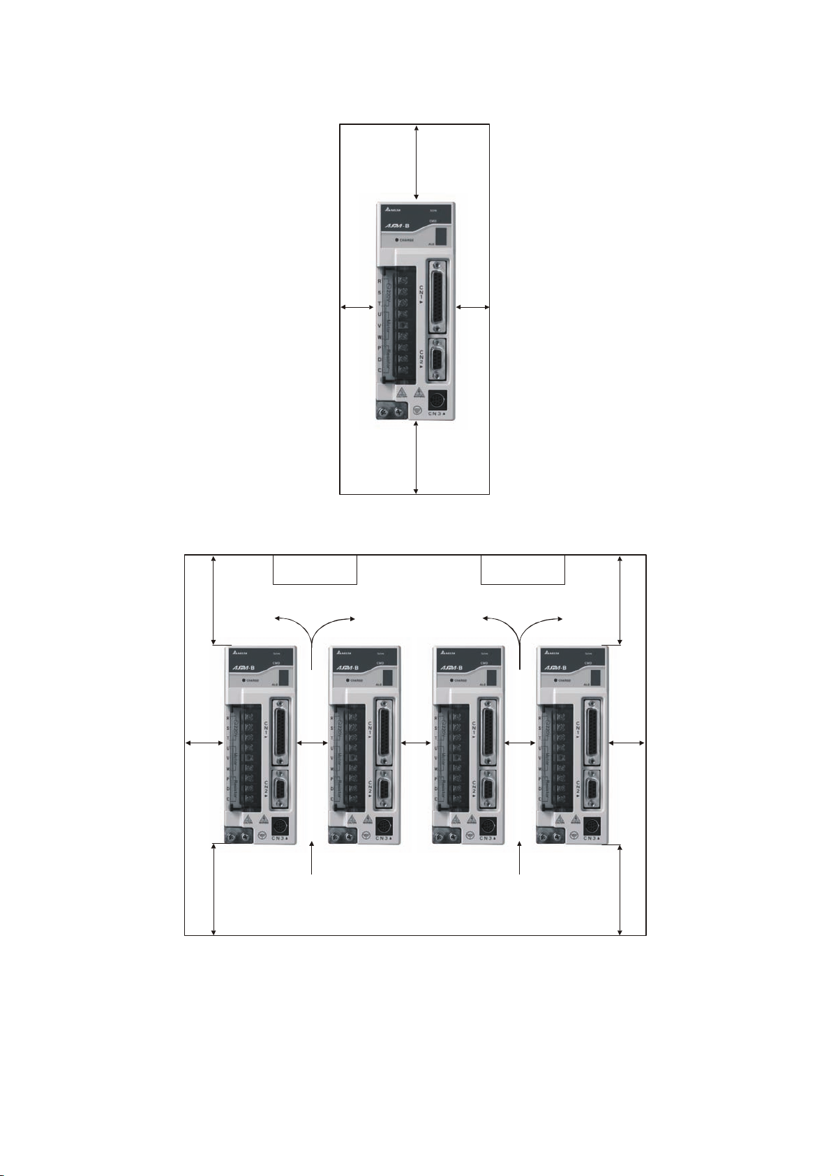
Minimum Clearances
Install a fan to increase ventilation to avoid ambient temperatures that exceed the specification. When
installing two or more drive adjacent to each other please follow the clearances as shown in the following
diagram.
Revision January 2009 2-3
Page 25
Chapter 2 Installation and Storage|ASDA-B Series
A
Minimum Clearances
2.0in
50mm()
min.
Side by Side Installation
4.0in
100mm
()
min.
0.8in
20mm()
min.
2.0in
50mm()
min.
0.8in
20mm()
min.
FAN FAN
4.0in
100mm
()
min.
1.6in
40mm()
min.
4.0in
100mm
()
min.
0.4in
10mm()
min.
0.4in
10mm()
min.
0.4in
10mm()
min.
ir flowAir flow
()
4.0in
100mm
min.
1.6in
40mm()
min.
2-4 Revision January 2009
Page 26
Chapter 3 Connections and Wiring
This chapter provides information on wiring ASDA-B series products, the descriptions of I/O signals and
gives typical examples of wiring diagrams.
3.1 Connections
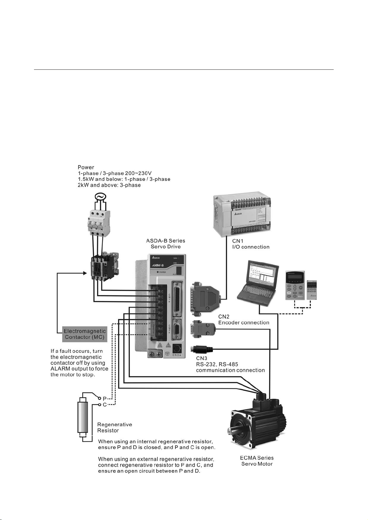
3.1.1 Connecting to Peripheral Devices
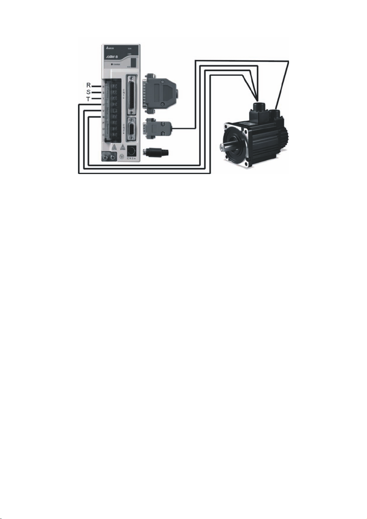
In Figure 3.1, it briefly explains how to connect each peripheral device.
Figure 3.1
Revision January 2009 3-1
Page 27
Chapter 3 Connections and Wiring|ASDA-B Series
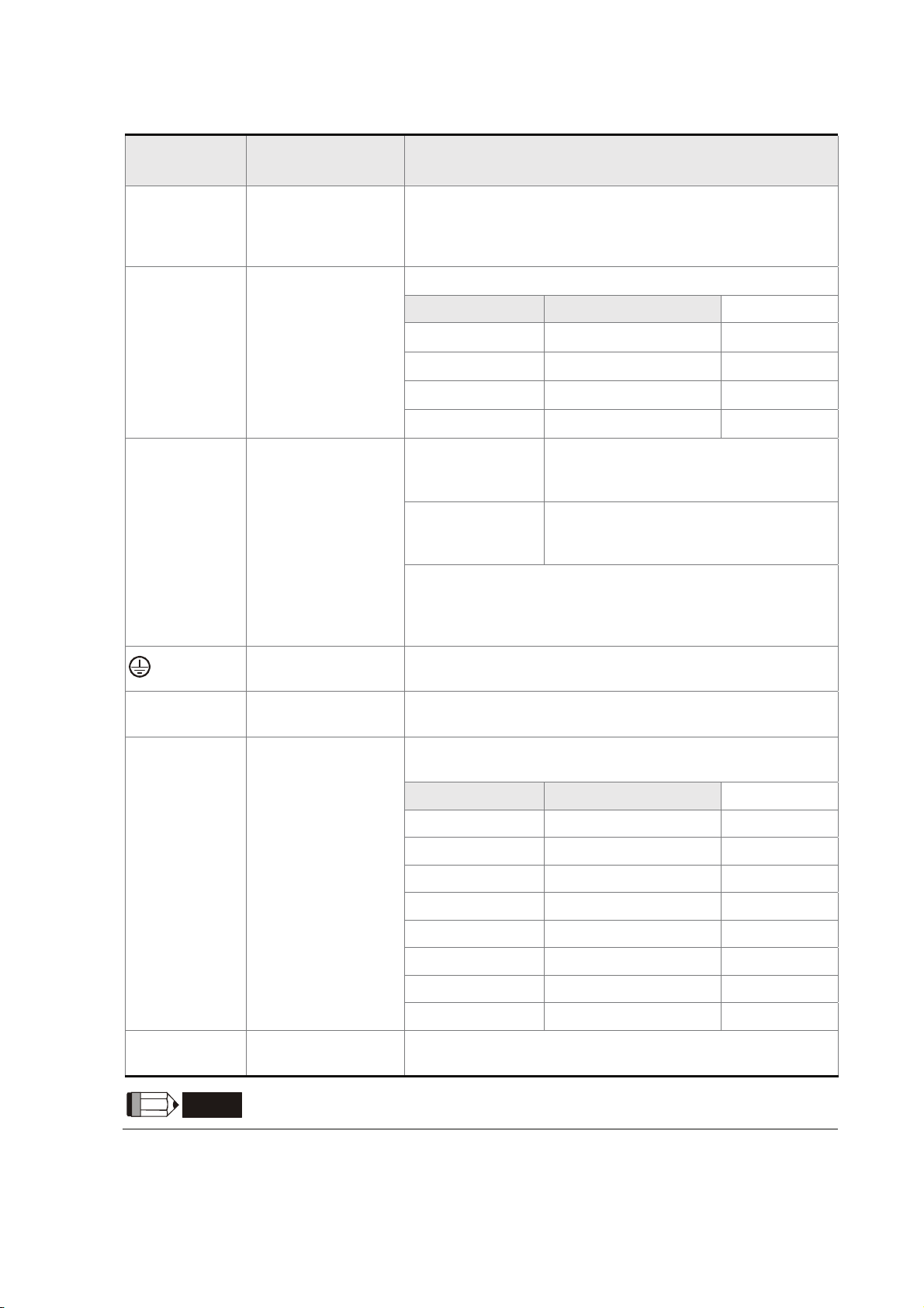
3.1.2 Servo Drive Connectors and Terminals
Terminal
Identification
R, S, T
U, V, W
FG
P, D, C
Terminal
Description
Main circuit terminal
Servo motor output
Regenerative
resistor terminal
Notes
The Main Circuit Terminal is used to supply the servo with
line power. If a single-phase supply, is used connect the R
and S terminals to power. If 3-phase, connect all three R, S,
& T terminals.
Used to connect servo motor
Terminal Symbol Wire Color
U Red
V White
W Black
FG Green
Ensure the circuit is closed between P
Internal resistor
External resistor
Only 750W and above servo drives are provided with builtin regenerative resistors. Ensure to leave the circuit closed
between P and D when using a built-in (internal)
regenerative resistor.
and D, and the circuit is open between
P and C.
Connect regenerative resistor to P and
C, and ensure an open circuit between
P and D.
two places
CN1
CN2
CN3
NOTE
Ground terminal
I/O connector
Encoder connector
Communication
connector
Used to connect grounding wire of power supply and servo
motor.
Used to connect external controllers. Please refer to section
3.3 for details.
Used to connect encoder of servo motor. Please refer to
section 3.4 for details.
Terminal Symbol Wire Color
A Black
/A Black/Red
B White
/B White/Red
Z Orange
/Z Orange/Red
+5V Brown & Brown/White
GND Blue & Blue/White
Used to connect PC or keypad. Please refer to section 3.5
for details.
1) U, V ,W , CN1, CN2, CN3 terminals provide short circuit protection.
3-2 Revision January 2009
Page 28

Chapter 3 Connections and Wiring|ASDA-B Series
Wiring Notes
Please observe the following wiring notes while performing wiring and touching any electrical
connections on the servo drive or servo motor.
1. Ensure to check if the power supply and wiring of the "power" terminals (R, S, T, U, V, & W) is
correct.
2. Please use shielded twisted-pair cables for wiring to prevent voltage coupling and eliminate
electrical noise and interference.
3. As a residual hazardous voltage may remain inside the drive, please do not immediately touch
any of the "power" terminals (R, S, T, U, V, & W) and/or the cables connected to them after the
power has been turned off and the charge LED is lit. (Please refer to the Safety Precautions on
page iii).
4. The cables connected to R, S, T and U, V, W terminals should be placed in separate conduits
from the encoder or other signal cables. Separate them by at least 30cm (11.8inches).
5. If the encoder cable is too short, please use a twisted-shield signal wire with grounding
conductor. The wire length should be 20m (65.62ft.) or less. For lengths greater than 20m
(65.62ft.), the wire gauge should be doubled in order to lessen any signal attenuation.
6. As for motor cable selection, please use the 600V PTFE wire and the wire length should be less
than 30m (98.4ft.). If the wiring distance is longer than 30m (98.4ft.), please choose the
adequate wire size according to the voltage.
7. The shield of shielded twisted-pair cables should be connected to the SHIELD end (terminal
marked
) of the servo drive.
8. For the connectors and cables specifications, please refer to section 3.1.6 for details.
9. In this manual, actual measured values are in metric units. The recommended wire lengths in
(imperial units) are for reference only. Please use metric for precise measurements.
Revision January 2009 3-3
Page 29
Chapter 3 Connections and Wiring|ASDA-B Series
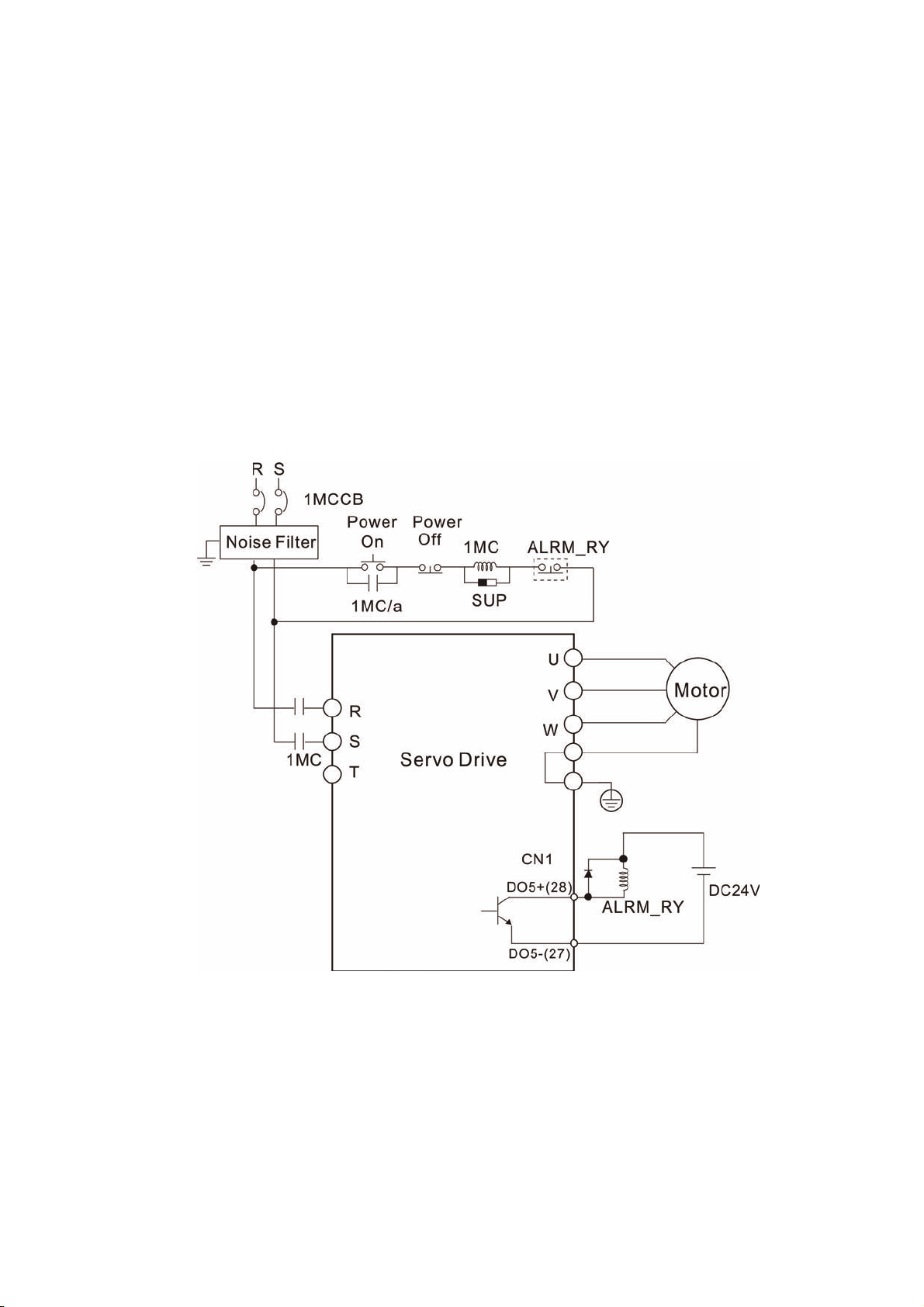
3.1.3 Wiring Methods
For servo drives 1.5kW and below the input power can be either single or three-phase. For drives 2kW
and above only three-phase connections are available.
In the wiring diagram figures 3.2 & 3.3:
Power ON : contact “a” (normally open)
Power OFF or Alarm Processing : contact “b” (normally closed)
1MC/x : coil of electromagnetic contactor
1MC/a : self-holding power
1MC : contact of main circuit power
Figure 3.2 Single-Phase Power Supply Connection
3-4 Revision January 2009
Page 30
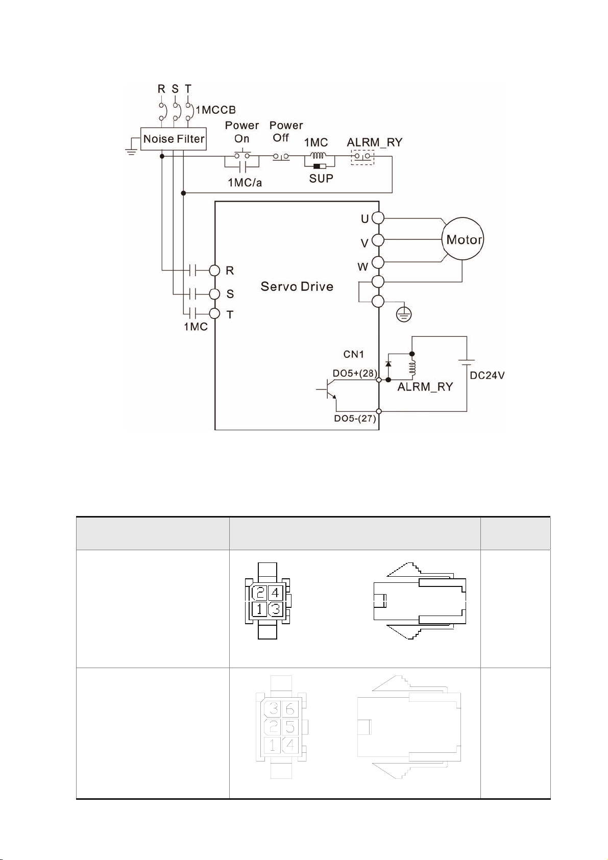
Chapter 3 Connections and Wiring|ASDA-B Series
Figure 3.3 Three-Phase Power Supply Connection
3.1.4 Motor Power Cable Connector Specifications
The boxes () in the model names are for optional configurations. (Please refer to section 1.2 for model
explanation.)
Motor Model Name U, V, W / Electromagnetic Brake Connector
ECMA-C30401S (100W)
ECMA-C30602S (200W)
ECMA-C30604S (400W)
ECMA-C308047 (400W)
ECMA-C30807S (750W)
HOUSING: JOWLE (C4201H00-2*2PA)
ECMA-C30602S (200W)
ECMA-C30604S (400W)
ECMA-C308047 (400W)
ECMA-C30807S (750W)
Terminal
Identification
A
B
HOUSING: JOWLE (C4201H00-2*3PA)
Revision January 2009 3-5
Page 31
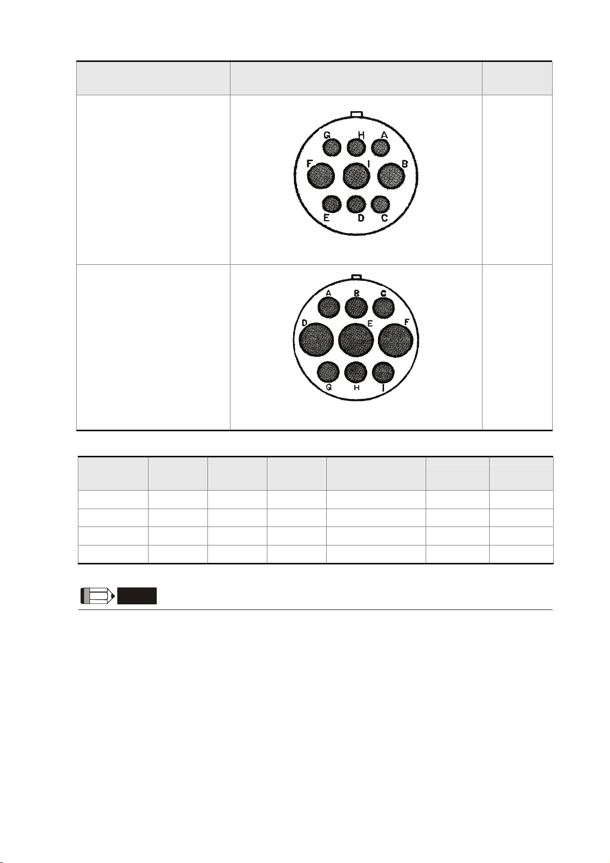
Chapter 3 Connections and Wiring|ASDA-B Series
Motor Model Name U, V, W / Electromagnetic Brake Connector
ECMA-G31303S (300W)
ECMA-E31305S (500W)
ECMA-G31306S (600W)
ECMA-G31309S (900W)
ECMA-C31010S (1000W)
ECMA-E31310S (1000W)
ECMA-E31315S (1500W)
ECMA-C31020S (2000W)
ECMA-E31320S (2000W)
3106A-20-18S
ECMA-E31820S (2000W)
Terminal
Identification
C
D
3106A-24-11S
(Red)
U
Terminal
Identification
A 1 2 3 4 - -
B 1 2 4 5 3 6
C F I B E G H
D D E F G A B
NOTE
1) The coil of brake has no polarity. The names of terminal identification are BRAKE1 and BRAKE2.
2) The power supply for brake is DC24V. Never use it for VDD, the +24V source voltage.
V
(White)
W
(Black)
CASE GROUND
(Green)
BRAKE1 BRAKE2
3-6 Revision January 2009
Page 32

Chapter 3 Connections and Wiring|ASDA-B Series
3.1.5 Encoder Connector Specifications
The boxes () in the model names are for optional configurations. (Please refer to section 1.2 for model
explanation.)
Motor Model Name Encoder Connector
ECMA-C30401S (100W)
ECMA-C30602S (200W)
ECMA-C30604S (400W)
ECMA-C308047 (400W)
ECMA-C30807S (750W)
HOUSING: AMP (1-172161-9)
ECMA-G31303S (300W)
ECMA-E31305S (500W)
ECMA-G31306S (600W)
ECMA-G31309S (900W)
ECMA-C31010S (1000W)
ECMA-E31310S (1000W)
ECMA-E31315S (1500W)
ECMA-C31020S (2000W)
ECMA-E31320S (2000W)
ECMA-E31820S (2000W)
3106A-20-29S
Terminal
Identification
A
B
Terminal
Identification
AMP (1-
172161-9)
A
(Black)
/A
(Black
/Red)
B
(White)
/B
(White
/Red)
Z
(Orange)
/Z
(Orange
/Red)
+5V
(Brown &
Brown/White)
GND
(Blue &
Blue/White)
BRAID
SHELD
A 1 4 2 5 3 6 7 8 9
Terminal
Identification
3106A-20-
29S
A
(Blue)
/A
(Blue
/Black)
B
(Green)
/B
(Green
/Black)
Z
(Yellow)
/Z
(Yellow
/Black)
+5V
(Red & Red
/White)
GND
(Black &
Black
/White)
BRAID
SHELD
B A B C D F G S R L
Revision January 2009 3-7
Page 33

Chapter 3 Connections and Wiring|ASDA-B Series
3.1.6 Cable Specifications for Servo Drive and Servo Motor
Servo Drive and Servo Motor
ASD-B0121-A ECMA-C30401S 2.1 (AWG14) 0.82 (AWG18) 2.1 (AWG14)
ASD-B0221-A ECMA-C30602S 2.1 (AWG14) 0.82 (AWG18) 2.1 (AWG14)
ECMA-C30604S 2.1 (AWG14) 0.82 (AWG18) 2.1 (AWG14)
ASD-B0421-A
ASD-B0721-A
ASD-B1021-A
ASD-B1521-A ECMA-E31315S 2.1 (AWG14) 1.3 (AWG16) 2.1 (AWG14)
ASD-B2023-A
ECMA-C308047 2.1 (AWG14) 0.82 (AWG18) 2.1 (AWG14)
ECMA-E31305S 2.1 (AWG14) 0.82 (AWG18) 2.1 (AWG14)
ECMA-G31303S 2.1 (AWG14) 0.82 (AWG18) 2.1 (AWG14)
ECMA-C30807S 2.1 (AWG14) 0.82 (AWG18) 2.1 (AWG14)
ECMA-G31306S 2.1 (AWG14) 0.82 (AWG18) 2.1 (AWG14)
ECMA-C31010S 2.1 (AWG14) 1.3 (AWG16) 2.1 (AWG14)
ECMA-E31310S 2.1 (AWG14) 1.3 (AWG16) 2.1 (AWG14)
ECMA-G31309S 2.1 (AWG14) 1.3 (AWG16) 2.1 (AWG14)
ECMA-C31020S 2.1 (AWG14) 2.1 (AWG14) 2.1 (AWG14)
ECMA-E31320S 2.1 (AWG14) 2.1 (AWG14) 2.1 (AWG14)
ECMA-E31820S 2.1 (AWG14) 3.3 (AWG12) 2.1 (AWG14)
Power Cable - Wire Gauge mm2 (AWG)
R,S,T U,V,W P,C
Encoder Cable - Wire Gauge mm2 (AWG)
Servo Drive and Servo Motor
ASD-B0121-A ECMA-C30401S 0.13 (AWG26) 10 core (4 pair) UL2464 3m (9.84ft.)
ASD-B0221-A ECMA-C30602S 0.13 (AWG26) 10 core (4 pair) UL2464 3m (9.84ft.)
ECMA-C30604S 0.13 (AWG26) 10 core (4 pair) UL2464 3m (9.84ft.)
ASD-B0421-A
ASD-B0721-A
ASD-B1021-A
ASD-B1021-A ECMA-G31309S 0.13 (AWG26) 10 core (4 pair) UL2464 3m (9.84ft.)
ASD-B1521-A ECMA-E31315S 0.13 (AWG26) 10 core (4 pair) UL2464 3m (9.84ft.)
ASD-B2023-A
ECMA-C308047 0.13 (AWG26) 10 core (4 pair) UL2464 3m (9.84ft.)
ECMA-E31305S 0.13 (AWG26) 10 core (4 pair) UL2464 3m (9.84ft.)
ECMA-G31303S 0.13 (AWG26) 10 core (4 pair) UL2464 3m (9.84ft.)
ECMA-C30807S 0.13 (AWG26) 10 core (4 pair) UL2464 3m (9.84ft.)
ECMA-G31306S 0.13 (AWG26) 10 core (4 pair) UL2464 3m (9.84ft.)
ECMA-C31010S 0.13 (AWG26) 10 core (4 pair) UL2464 3m (9.84ft.)
ECMA-E31310S 0.13 (AWG26) 10 core (4 pair) UL2464 3m (9.84ft.)
ECMA-C31020S 0.13 (AWG26) 10 core (4 pair) UL2464 3m (9.84ft.)
ECMA-E31320S 0.13 (AWG26) 10 core (4 pair) UL2464 3m (9.84ft.)
ECMA-E31820S 0.13 (AWG26) 10 core (4 pair) UL2464 3m (9.84ft.)
Wire Size Core Number UL Rating
Standard
Wire Length
(Please refer to Section 1.2 for model explanation)
NOTE
1) Please use shielded twisted-pair cables for wiring to prevent voltage coupling and eliminate
electrical noise and interference.
2) The shield of shielded twisted-pair cables should be connected to the SHIELD end (terminal
marked
3-8 Revision January 2009
) of the servo drive.
Page 34

Chapter 3 Connections and Wiring|ASDA-B Series
3.2 Basic Wiring
Figure 3.4 Basic Wiring Schematic of 400W and below models
Revision January 2009 3-9
Page 35

Chapter 3 Connections and Wiring|ASDA-B Series
Figure 3.5 Basic Wiring Schematic of 750W models
3-10 Revision January 2009
Page 36

Chapter 3 Connections and Wiring|ASDA-B Series
Figure 3.6 Basic Wiring Schematic of 1kW and above models
Revision January 2009 3-11
Page 37

Chapter 3 Connections and Wiring|ASDA-B Series
3.3 Input / Output Interface Connector -CN1
The CN1 Interface Connector provides access to three signal groups:
i General interface for the analog speed and torque control, encoder reference signal from the motor,
open collector and line driver inputs, and reference voltages.
ii 6 programmable Digital Inputs (DI), can be set via parameters P2-10 ~ P2-15
iii 3 programmable Digital Outputs (DO), can be set via parameters P2-18 ~ P2-20
A detailed explanation of each group is available in Section 3.3.2, Tables 3.A, 3.B & 3.C.
3.3.1 CN1 Terminal Identification
Figure 3.7 The Layout of CN1 Drive Connector:
1
14
13
CN1 Terminal Signal Identification
1 D03+
2 DO2+
3 DI4- Digital input
4 COM+ DI input common voltage rail
5 DI3- Digital input
6 T-REF Analog torque input (+)
7 VDD +24Vpower output (for external I/O)
8 GND Analog input signal ground
9 V-REF Analog speed input (+)
10 OA Encoder A pulse output
11 /OB Encoder /B pulse output
12 OB Encoder B pulse output
13 COM- VDD(24V) power ground
Digital output
Digital output
25
14 DI6- Digital input
15 DI5- Digital input
16 DO1+
17 DI1- Digital input
18 DI2- Digital input
19 /SIGN Position sign (-)
20 SIGN Position sign (+)
21 /PULSE Pulse input (-)
22 PULSE Pulse input (+)
23 /OA Encoder /A pulse output
24 OZ Encoder Z pulse output
25 /OZ Encoder /Z pulse output
Digital output
3-12 Revision January 2009
Page 38

Chapter 3 Connections and Wiring|ASDA-B Series
NOTE
1) GND (Pin 8) and COM- (Pin 13) of CN1 connector are independent respectively and do not have
connection with the ground terminal outside the servo drive.
3.3.2 Signals Explanation of Connector CN1
The Tables 3.A, 3.B, & 3.C detail the three groups of signals of the CN1 interface. Table 3.A details the
general signals. Table 3.B details the Digital Output (DO) signals and Table 3.C details the Digital Input
(DI) signals. The General Signals are set by the factory and can not be changed, reprogrammed or
adjusted. Both the Digital Input and Digital Output signals can be programmed by the users.
Table 3.A General Signals
Signal Pin No Details
Motor speed command: -10V to +10V, corresponds to
Analog
Signal
Input
V_REF 9
T_REF 6
the maximum speed programmed P1-55 Maximum
Speed Limit (Factory default 3000 RPM).
Motor torque command: -10V to +10V, corresponds
to -100% to +100% rated torque command.
Wiring Diagram
(Refer to 3.3.3)
C1
C1
PULSE
Position
Pulse
Input
Position
Pulse
Output
Power
Ground
The Digital Input (DI) and Digital Output (DO) have factory default settings which correspond to the
/PULSE
SIGN
/SIGN
OA
/OA
OB
/OB
OZ
/OZ
VDD 7
COM+
COM-
GND 8 Analog input signal ground.
22
21
20
19
10
23
12
11
24
25
4
13
The drive can accept two different types of pulse
inputs: Open Collector and Line Driver.
Three different pulse commands can be selected via
parameter P1-00. Quadrature, CW + CCW pulse &
Pulse / Direction.
The motor encoder signals are available through
these terminals. The A, B, Z output signals can be
Line Driver type. The Z output signal can be Open
Collector type also, but the output maximum voltage
is 5V and the maximum permissible current is
200mA.
VDD is the +24V source voltage provided by the
drive. Maximum permissible current is 500mA.
COM+ is the common voltage rail of the Digital Input
and Digital Output signals. Connect VDD to COM+ for
source mode. For external applied power sink mode
(+12V to +24V), the positive terminal should be
connected to COM+ and the negative to COM-.
C2/C3
C10/C11
-
-
various servo drive control modes. (See section 1.5). However, both the DI's and DO's can be
programmed independently to meet the requirements of the users.
Detailed in Tables 3.B and 3.C are the DO and DI functions with their corresponding signal name and
wiring schematic. The factory default settings of the DI and DO signals are detailed in Table 3.F.
Revision January 2009 3-13
Page 39

Chapter 3 Connections and Wiring|ASDA-B Series
All of the DI's and DO's and their corresponding pin numbers are factory set and nonchangeable,
however, all of the assigned signals and control modes are user changeable. For Example, the factory
default setting of DO1 (pin 16) is SRDY (servo ready) signal, but it can be assigned to SON (Servo On)
signal and vise versa.
The following Tables 3.B and 3.C detail the functions, applicable operational modes, signal name and
relevant wiring schematic of the default DI and DO signals.
Table 3.B DO Signals
DO
Signal
Assigned
Control Mode
Pin No.
+
SRDY is activated when the servo drive is
16
SRDY ALL
(DO1)
ready to run. All fault and alarm conditions, if
present, have been cleared.
SON is activated when control power is
applied to the servo drive. The drive may or
may not be ready to run as a fault / alarm
condition may exist.
SON ALL -
Servo ON (SON) is "ON" with control power
applied to the servo drive, there may be a fault
condition or not. The servo is not ready to run.
Servo ready (SRDY) is "ON" where the servo
is ready to run, NO fault / alarm exists.
ZSPD is activated when the drive senses the
motor is equal to or below the Zero Speed
Range setting as defined in parameter P1-38.
2
ZSPD ALL
(DO2)
For Example, at default ZSPD will be activated
when the drive detects the motor rotating at
speed at or below 10 rpm. ZSPD will remain
activated until the motor speed increases
above 10 RPM.
Details
(*1)
Wiring Diagram
(Refer to 3.3.3)
C4/C5/C6/C7
TSPD is activated once the drive has detected
the motor has reached the Target Rotation
TSPD ALL -
Speed setting as defined in parameter P1-39.
TSPD will remain activated until the motor
speed drops below the Target Rotation Speed.
When the drive is in P mode, TPOS will be
TPOS P -
activated when the position error is equal and
below the setting value of P1-54.
TQL is activated when the drive has detected
TQL ALL -
that the motor has reached the torques limits
set by either the parameters P1-12 ~ P1-14.
ALRM is activated when the drive has
detected a fault condition. (However, when
1
ALRM ALL
(DO3)
Reverse limit error, Forward limit error,
Emergency stop, Serial communication error,
and Undervoltage these fault occur, WARN is
activated first.)
BRKR ALL - BRKR is activated actuation of motor brake.
OLW is activated when the servo drive has
OLW ALL -
detected that the motor has reached the
output overload level set by parameter P2-37.
3-14 Revision January 2009
Page 40

Chapter 3 Connections and Wiring|ASDA-B Series
DO
Signal
Assigned
Control Mode
Pin No.
+
Details
(*1)
Wiring Diagram
(Refer to 3.3.3)
Servo warning output. WARN is activated
when the drive has detected Reverse limit
WARN ALL -
error, Forward limit error, Emergency stop,
Serial communication error, and Undervoltage
these fault conditions.
Footnote *1: The "state" of the output function may be turned ON or OFF as it will be dependant on the
settings of P2-10~P2-15.
Table 3.C DI Signals
DI
Signal
SON
Assigned
Control Mode
Pin No. Details
(*2)
ALL 17 Servo On. Switch servo to "Servo Ready".
Wiring Diagram
(Refer to 3.3.3)
A number of Faults (Alarms) can be cleared by
activating ARST. Please see section 10.3 for
applicable faults that can be cleared with the
ARST
ALL 18
ARST command. However, please investigate
Fault or Alarm if it does not clear or the fault
description warrants closer inspection of the
drive system.
GAINUP
CCLR
ZCLAMP
CMDINV
INHP
TRQLM
SPDLM
ALL - Gain switching in speed and position mode
When CCLR is activated the setting is
P 5
parameter P2-48 Pulse Clear Mode is
executed.
When this signal is On and the motor speed
value is lower than the setting value of P1-38,
it is used to lock the motor in the instant
S , T -
position while ZCLAMP is On.
The parameter P2-38 should be enabled first if
the users want to set the speed command that
has been accelerated and decelerated more
smoothly.
ALL -
When this signal is On, the motor is in reverse
rotation.
Pulse inhibit input. When the drive is in
P -
position mode, if INHP is activated, the
external pulse input command is not valid.
P , S , Sz -
T , Tz -
ON indicates the torque limit command is
valid.
ON indicates the speed limit command is
valid.
C8/C9
GNUM0
SPD0
SPD1
Revision January 2009 3-15
P - Electronic gear ratio (Numerator) selection 0
ALL -
Select the source of speed command:
See Table 3.D.
Page 41

Chapter 3 Connections and Wiring|ASDA-B Series
DI
Signal
TCM0
TCM1
S-P
S-T
T-P
EMGS
CWL
CCWL
Assigned
Control Mode
Pin No. Details
ALL -
Sz , S , P -
Sz , S , Tz -
T , Tz , P -
ALL 14
ALL 3
ALL 15
(*2)
Select the source of torque command:
See Table 3.E.
Speed / Position mode switching
OFF: Speed, ON: Position
Speed / Torque mode switching
OFF: Speed, ON: Torque
Torque / Position mode switching
OFF: Torque, ON: Position
It should be contact “b” and normally ON or a
fault (ALE13) will display.
Reverse inhibit limit. It should be contact “b”
and normally ON or a fault (ALE14) will
display.
Forward inhibit limit. It should be contact “b”
and normally ON or a fault (ALE15) will
display.
Wiring Diagram
(Refer to 3.3.3)
C8/C9
TLLM
P , S -
Torque limit - Reverse operation (Torque limit
function is valid only when P1-02 is enabled)
TRLM
P , S -
Torque limit - Forward operation (Torque limit
function is valid only when P1-02 is enabled)
Footnote *2: The "state" of the input function may be turned ON or OFF as it will be dependant on the
settings of P2-18~P2-20.
Table 3.D Source of Speed Command Table 3.E Source of Torque Command
SPD1 SPD0 Parameter TCM1 TCM0 Parameter
OFF OFF
S mode: analog input
Sz mode: 0
OFF OFF
T mode: analog input
Tz mode: 0
OFF ON P1-09 OFF ON P1-12
ON OFF P1-10 ON OFF P1-13
ON ON P1-11 ON ON P1-14
The user-defined DI and DO signals are defined via parameters P2-10 to P2-15 and P2-18 to P2-20.
Please refer to the following Table 3.F for the settings. Although the content of the Table 3.F does not
provide more information than the Table 3.B and Table 3.C above, as each control mode is separated
and listed in different row, it is easy for the users to view and can avoid confusion. However, the Pin
number of each signal can not be displayed in the Table 3.F.
3-16 Revision January 2009
Page 42

Chapter 3 Connections and Wiring|ASDA-B Series
Table 3.F Default DI Signals and DO Signals
The factory default settings of DI signals
Signal DI Code Function Default Settings
SON 01 Servo On DI1
ARST 02 Alarm Reset DI2
GAINUP 03 Gain switching in speed and position mode
CCLR 04 Pulse clear DI3
ZCLAMP 05 Zero speed CLAMP
CMDINV 06 Command input reverse control
INHP 07 Pulse inhibit input
TRQLM 09 Torque limit enabled
SPDLM 10 Speed limit enabled
GNUM0 11 Electronic gear ratio (Numerator) selection 0
SPD0 14 Speed command selection 0
SPD1 15 Speed command selection 1
TCM0 16 Torque command selection 0
TCM1 17 Torque command selection 1
S-P 18
S-T 19
T-P 20
Position / Speed mode switching (OFF: Speed, ON:
Position)
Speed / Torque mode switching (OFF: Speed, ON:
Torque)
Torque / Position mode switching (OFF: Torque,
ON: Position)
EMGS 21 Emergency stop (contact b) DI6
CWL 22 Reverse inhibit limit (contact b) DI4
CCWL 23 Forward inhibit limit (contact b) DI5
TLLM 25 Torque limit - Reverse operation
TRLM 26 Torque limit - Forward operation
The factory default settings of DO signals
Signal DO Code Function Default Settings
SRDY 01 Servo ready DO1
SON 02 Servo On
ZSPD 03 At Zero speed DO2
TSPD 04 At Speed reached
TPOS 05 At Positioning completed
TQL 06 At Torques limit
ALRM 07 Servo alarm (Servo fault) activated DO3
BRKR 08 Electromagnetic brake control
OLW 09 Output overload warning
WARN 10 Servo warning activated
Revision January 2009 3-17
Page 43

Chapter 3 Connections and Wiring|ASDA-B Series
3.3.3 User-defined DI and DO signals
If the default DI and DO signals could not be able to fulfill the users’ requirements, there are still user-
defined DI and DO signals. The setting method is easy and they are all defined via parameters. The
user-defined DI and DO signals are defined via parameters P2-10 to P2-15 and P2-18 to P2-20.
Please refer to the following Table 3.G for the settings.
Table 3.G User-defined DI and DO signals
Signal Name
DI1- 17 P2-10 DO1+ 16 P2-18
DI2- 18 P2-11 DO2+ 2 P2-19
DI3- 5 P2-12
DI
DI4- 3 P2-13
DI5- 15 P2-14
DI6- 14 P2-15
Default Pin
No.
Parameter Signal Name
DO
DO3+ 1 P2-20
Default Pin
No.
Parameter
DI signal:
For example: If the users want to set DI1 to be servo on, it only needs to set the value of parameter P2-
10 to 101 (refer to chapter 7).
NOTE
1) 14~17: Single control mode;18~20: Dual control mode; 0: Input function disabled
Setting of parameter P2-10 to P2-15:
DI Code Signal Description
01 SON Servo On
02 ARST Alarm Reset
03 GAINUP Gain switching in speed and position mode
04 CCLR Pulse clear
05 ZCLAMP Zero speed CLAMP
06 CMDINV Command input reverse control
07 INHP Pulse inhibit input
09 TRQLM Torque limit enabled
10 SPDLM Speed limit enabled
11 GNUM0 Electronic gear ratio (Numerator) selection 0
14 SPD0 Speed command selection 0
15 SPD1 Speed command selection 1
16 TCM0 Torque command selection 0
17 TCM1 Torque command selection 1
18 S-P Position / Speed mode switching (OFF: Speed, ON: Position)
3-18 Revision January 2009
Page 44
Chapter 3 Connections and Wiring|ASDA-B Series
Setting of parameter P2-10 to P2-15:
DI Code Signal Description
19 S-T Speed / Torque mode switching (OFF: Speed, ON: Torque)
20 T-P Torque / Position mode switching (OFF: Torque, ON: Position)
21 EMGS Emergency stop (contact b)
22 CWL Reverse inhibit limit (contact b)
23 CCWL Forward inhibit limit (contact b)
25 TLLM Torque limit - Reverse operation
26 TRLM Torque limit - Forward operation
DO signal:
For example: If the users want to set DO1 to be servo ready, it only needs to set the value of parameter
P2-18 to 101 (refer to chapter 7).
NOTE
1) 0: Output function disabled
DO Code Signal Description
01 SRDY Servo ready
02 SON Servo On
03 ZSPD At Zero speed
04 TSPD At Speed reached
05 TPOS At Positioning completed
06 TQL At Torques limit
07 ALRM Servo alarm (Servo fault) activated
08 BRKR Electromagnetic brake control
09 OLW Output overload warning
10 WARN Servo warning activated
Setting of parameter P2-18 to P2-20:
Revision January 2009 3-19
Page 45

Chapter 3 Connections and Wiring|ASDA-B Series
3.3.4 Wiring Diagrams of I/O Signals (CN1)
The valid voltage range of analog input command in speed and torque mode is -10V ~+10V.
The command value can be set via relevant parameters.
C1: Speed / Torque analog signal input
There are two kinds of pulse inputs, Line driver input and Open-collector input. Max. input pulse
frequency of Line driver input is 500kpps and max. input pulse frequency of Open-collector input is
200kpps.
NOTE
1) In order to protect the internal circuit, when using open collector input, please
ensure to connect one 1 ~ 2 KΩ current limit resistor before Pin 19(/SIGN) and
Pin 21(/PULSE) respectively (Please refer to the wiring diagram on next page).
2) For the specifications of connected current limit resistor, please refer to the
table below:
Vdc Specifications
24V 1KΩ
12V 500Ω
−
2Vdc
Equation: mA
100
≅
20
+
R
3-20 Revision January 2009
Page 46

Chapter 3 Connections and Wiring|ASDA-B Series
S
S
C2-1: Pulse input (Open collector – internal power)
ervo Drive
Please ensure to
connect the resistor
or the photocoupler
may be damaged due
to excessive current.
C2-2: Pulse input (Open collector – external power)
Approx.
1K
Approx.
1K
7
VDD
19 /SIGN
20 SIGN
21 /PULSE
22 PULSE
COM-
13
DC24V
Max. input pulse
frequency is 200kpps
50
50
50
50
ervo Drive
Please ensure to
connect the resistor
or the photocoupler
may be damaged
due to excessive
current.
Vdc
Approx.
1K
Approx.
1K
7
VDD
19 /SIGN
20 SIGN
21 /PULSE
DC24V
Ma x. in put p ulse
frequency is 200kpps
50
50
50
22 PULSE
50
COM-
13
Revision January 2009 3-21
Page 47

Chapter 3 Connections and Wiring|ASDA-B Series
C3: Pulse input (Line Driver)
Because this
photocoupler is a
unidirectional
optocoupler, please pay
close attention on the
current direction of input
pulse command.
Be sure to connect a diode when the drive is applied to inductive load.
(Continuous maximum current: 40mA, Instantaneous peak current: max. 100mA)
C4: Wiring of DO signal, for the use of internal power supply, general load
C5: Wiring of DO signal, for the use of internal power supply, inductive load
3-22 Revision January 2009
Page 48

Chapter 3 Connections and Wiring|ASDA-B Series
C6: Wiring of DO signal, for the use of external
C7: Wiring of DO signal, for the use of external
power supply, general load
Use a relay or open-collector transistor to input signal.
C8: Wiring of DI signal, for the use of internal
C9: Wiring of DI signal, for the use of internal
power supply
power supply, inductive load
power supply
C10: Encoder output signal (Line driver) C11: Encoder output signal (Photocoupler)
Revision January 2009 3-23
Page 49

Chapter 3 Connections and Wiring|ASDA-B Series
3.4 Encoder Connector CN2
Integrated within the servo motor is an incremental encoder with 2,500PPR and commutation signal.
When power is first applied to the servo drive, control algorithms detect the motor's rotor position through
imbedded sensors in the motor within 500msec approximately.
Feedback to the amplifier of the UVW signals for commutation is via the ABZ encoder signal wires. Following
rotor position sensing the amplifier automatically switches to encoding for commutation control.
The 2500PPR encoder is automatically multiplied to 10000PPR by X4 logic for increased control accuracy.
Figure 3.8 The layout of CN2 Drive Connector:
Pin No Signal Name
4 A phase input A
5 /A phase input /A
3 B phase input B
2 /B phase input /B
Identification
1
5
CN2 Terminal Signal Identification
Terminal
Description
Encoder A phase
output
Encoder /A phase
output
Encoder B phase
output
Encoder /B phase
output
6
9
Connector
Military
A A1 Black
B A4 Black / Red
C A2 White
D A5 White / Red
Fast
Connector
Wire Color
9 Z phase input Z
1 /Z phase input /Z
8 Encoder power +5V Encoder 5V power S A7
6, 7 Encoder power GND Grounding R A8
Shielding Shielding Shielding L A9 Shielding
3-24 Revision January 2009
Encoder Z phase
output
Encoder /Z phase
output
F A3 Orange
G A6
Orange / Red
Brown &
Brown / White
Blue &
Blue / White
Page 50

Chapter 3 Connections and Wiring|ASDA-B Series
3.5 Serial Communication Connector CN3
3.5.1 CN3 Terminal Layout and Identification
The servo drive can be connected to a PC or controller via a serial communication connector. The users
can operate the servo drive through PC software supplied by Delta (contact to the dealer/distributor).
The communication connector/port of Delta servo drive can provide two common serial communication
interfaces: RS-232, and RS-485 connection. RS-232 is mostly be used but is somewhat limited. The
maximum cable length for an RS-232 connection is 15 meters (50 feet). Using RS-485 interface can
allow longer distance for transmission and support multiple drives to be connected simultaneously.
Figure 3.9 The layout of CN3 Drive Connector:
4
1
3
6
2
5
8
7
CN3 Drive Connector
CN3 Terminal Signal Identification
Pin No Signal Name
1 RS-485- RS-485-
2 Signal power +5VD
3 RS-485+ RS-485+
4
5
RS-232 data
receiving
RS-232 data
transmission
Terminal
Identification
RS-232-RX
RS-232-TX
Description
For data transmission of the servo drive.
Connected to the RS-485- interface of PC.
For data transmission of the servo drive.
Connected to the RS-485+ interface of PC.
For data receiving of the servo drive.
Connected to the RS-232 interface of PC.
For data transmission of the servo drive.
Connected to the RS-232 interface of PC.
Please refer to section 3.5.2.
RS-232 / RS-485
6
7
8 Grounding GND
1) In order to avoid the communication error, if the users use their own communication connector,
Revision January 2009 3-25
data format
selection
Re-flash
selection
NOTE
ensure the circuit between the connector case and all pins is not closed.
SEL232 / 485
Boot_Load
RS-232 & RS-485 data format selection
For RS-485 connection, connect SEL232/485(Pin6)
to GND(Pin8). For RS-232 connection, do not
connect SEL232/485(Pin6) to GND(Pin8).
Boot_Load terminal for DSP Reflash burn-in
selection (Do not connect this terminal).
Page 51

Chapter 3 Connections and Wiring|ASDA-B Series
2) When using RS-232 communication, the user can use the communication cable provided by Delta
PLC directly. (The PLC communication cable is compatible with all Delta Servo systems for the
users’ convenience)
3.5.2 Connection between PC/Keypad and Connector CN3
Connection between PC and CN3
4
2
3
5
5
4
1
3
6
8
7
2
5
8
PC or
Notebook
Connection between Keypad and CN3
5
1
3
5
7
9
KEYPAD
10
2
4
8
6
2
8
3
CN3 Dr i ve Co nnec tor
8
1
2
3
6
5
4
CN3 Drive Connector
4
2
5
8
7
3-26 Revision January 2009
Page 52

3.6 Standard Connection Example
3.6.1 Position Control Mode
Chapter 3 Connections and Wiring|ASDA-B Series
Revision January 2009 3-27
Page 53

Chapter 3 Connections and Wiring|ASDA-B Series
3.6.2 Speed Control Mode
3-28 Revision January 2009
Page 54

3.6.3 Torque Control Mode
Chapter 3 Connections and Wiring|ASDA-B Series
Revision January 2009 3-29
Page 55

Chapter 3 Connections and Wiring|ASDA-B Series
This page intentionally left blank.
3-30 Revision January 2009
Page 56

Chapter 4 Display and Operation
This chapter describes the basic operation of the digital keypad and the features it offers.
There are several modes of operation:
Monitor, Parameter, Parameter Setting, Save, Write and Fast Edit Mode.
In Monitor mode, users can display the monitor status. In Parameter mode, users can display and view the
parameter name, unit and setting value, and also can navigate in parameter groups. In Parameter Setting
mode, users can edit and change the parameter setting value. In Save mode, it allows users to save the
parameters stored in PC or the servo drive into the digital keypad. In Write mode, it allows users to write the
parameters out of the digital keypad and restored in the servo drive. Please note that the status monitor
function of the servo drive is disabled and the LED indicators on the digital keypad are invalid at this time
when in Save mode and Write mode. In Fast Edit mode, users can edit the parameters more quickly. Also,
static and dynamic auto-tuning is also provided in this mode.
If users desire to upgrade the firmware version of the digital keypad, please open the rear case of the keypad
and turn the switch to BOOTLOAD. Then, execute the PC program and the firmware will be upgraded.
For the keypad parameters and fault messages (Alarm codes), please refer to Chapter 7 and Chapter 10.
4.1 ASD-PU-01A
4.1.1 Description of Digital Keypad ASD-PU-01A
The digital keypad includes the ASD-PU-01A display panel and function keys. The Figure 4.1 shows all
of the features of the ASD-PU-01A digital keypad and an overview of their functions.
Figure 4.1
LCD Display
Status Display
(LED Indication)
MODE Key
UP and DOWN Key
SHIFT Key
JOG Key
RESET Key
WRITE Key
Revision January 2009 4-1
SET Key
Fast Edit Key
SAVE Key
Page 57

Chapter 4 Display and Operation|ASDA-B Series
Name Function
LCD Display
2 line × 16 character LCD display shows the monitor codes, parameter settings and
operation values of the AC servo drive.
SON LED (Servo On Indicator). A lit LED illuminates to indicate that the servo drive is
enabled.
ALRM LED (Alarm Output Indicator). A lit ALRM LED illuminates to indicates that a
alarm output is activated.
Status Display
(LED Indication)
JOG LED (JOG Operation Indicator). A lit JOG LED illuminates to indicates that JOG
operation is enabled.
TSPD LED (Speed reached Indicator). A lit TSPD LED illuminates to indicates that the
target speed is reached and TSPD signal is activated.
TPOS LED (Positioning completed Indicator). A lit TPOS LED illuminates to indicates
that the target position is reached and TPOS signal is activated.
MODE Key. Pressing MODE key can enter or exit different parameter groups, and
MODE
switch between Parameter mode and Parameter Setting mode, SAVE mode and
WRITE mode.
SHIFT Key. In Parameter mode, pressing SHIFT key can scrolls through parameter
SHIFT
groups. In Parameter Setting mode and SAVE mode, after a parameter is selected and
its value displayed, pressing SHIFT key can move the cursor to the left and then
change parameter settings (blinking digits) by using arrow keys.
UP and DOWN arrow Key. Pressing the UP and DOWN arrow key can scroll through
and change monitor codes, parameter groups and various parameter settings.
In SAVE and WRITE mode, pressing UP and DOWN arrow key can scroll through and
change the memory blocks. In SAVE mode, pressing UP and DOWN arrow key can
select and change the memory file name also.
SET Key. Pressing Set key can enter into the Parameter Setting mode, then display,
SET
select and save parameter groups and various parameter settings. During diagnosis
operation, pressing SET key can execute the function in the last step.
(The parameter settings changes are not effective until the SET key is pressed.)
JOG Key. Pressing JOG key can enable JOG operation immediately. 1st pressing:
JOG
enter JOG operation. 2nd pressing: exit JOG operation. Please refer to Section 4.4.3
for operation.
ARST
SAVE
WRITE
Reset Key. Pressing ARST key can Used to clear a fault (Alarm).
This key is available in any modes.
SAVE Key. Pressing SAVE key can save parameter settings to the digital keypad.
Please refer to Section 4.2.2 for operation.
WRITE Key. Pressing WRITE key can write out the parameter settings in the digital
keypad and send to the servo drive. Please refer to Section 4.2.3 for operation.
Fast Edit Key. Pressing Fast Edit key can use three special functions:
Fast Editing, Static Auto-tuning and Dynamic Auto-tuning.
Fast editing function:
1) 1st pressing: Enable the Fast Editing function. When Fast Editing function is
Fast Edit
enabled, using UP and DOWN arrow key can browse, search and edit the
parameters that have been edited before directly and quickly. The parameter
setting method is the same as usual.
2) 2nd pressing: Disable the Fast Editing function.
Static Auto-tuning and Dynamic Auto-tuning function: Please refer to Section 4.2.4
for operation.
NOTE
1) The functions of MODE, SHIFT, UP and DOWN, and SET keys are the same as the function keys of
ASDA-A series servo drive.
4-2 Revision January 2009
Page 58
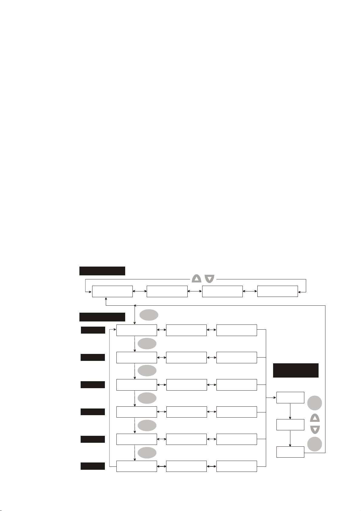
Chapter 4 Display and Operation|ASDA-B Series
4.1.2 Display Flowchart
Monitor Mode, Parameter Mode and Parameter Setting Mode
1. When the power is applied to the AC servo drive, the digital keypad will execute communication
initial setup for approximately two seconds (9600bps & 7,N,2 Modbus ASCII) first, and then enter
into the monitor mode.
2. In monitor mode, pressing UP or DOWN arrow key can switch monitor parameter code.
3. In monitor mode, pressing MODE key can enter into parameter mode, pressing the SHIFT key
can switch parameter group and pressing UP or DOWN arrow key can change parameter group
code.
4. In parameter mode, system will enter into the parameter setting mode immediately after the SET
key is pressed. The LCD display will display the corresponding setting value of this parameter
simultaneously. Then, users can use UP or DOWN arrow key to change parameter value or press
MODE key to exit and return back to the parameter mode.
5. In parameter setting mode, users can move the cursor to left by pressing the SHIFT key and
change the parameter settings (blinking digits) by pressing the UP or DOWN arrow key.
6. After the setting value change is completed, press SET key to save parameter settings or execute
command.
7. When the parameter setting is completed, LCD display will show the end code “-SET END-“ and
automatically return back to parameter mode.
Figure 4.2
Monitor Mode
STS00:Fb PULSE
0 p ulse
Parameter Mode
GROUP0
GROUP1
GROUP2
GROUP3
P0-00:VER
0.005
P1-00:PTT
2
P2-00:KPP
70 rad/s
P3-00:ADR
1
STS01:Fb REV
0 rev
MODE
SHIFT
SHIFT
SHIFT
SHIFT
P0-01:ALE
0
P1-01:CTL
0
P2-01:PPR
100 %
P3-01:BRT
3 bps
STS02:CMD PULSE
0 pulse
P0-02:STS
0
P1-02:PSTL
0
P2-02:PFG
50 %
P3-02:PTL
0
STS15:IGBT temp
3 3 d eg C
Parameter
Setting Mode
Edit Setting Values
10000
10001
SET
GROUP4
GROUP8
Revision January 2009 4-3
P4-00:ASH1
1
SHIFT
P8-00:VERSION
1.001
P4-01:ASH2
1
P8-01:MISC FUN
1
P4-02:ASH3
1
P8-05:KPD ID
255
SET
SET END
Save Setting Values
Page 59

Chapter 4 Display and Operation|ASDA-B Series
SAVE Mode (Save parameter settings from the Drive to the Keypad)
1. When the power is applied to the AC servo drive, the digital keypad will enter into the monitor
mode first.
2. In monitor mode, pressing SAVE key can switch to SAVE mode.
3. In SAVE mode, pressing SAVE key can execute the function the users select and save the new
parameter settings.
4. In SAVE mode, pressing UP and DOWN key can save the desired memory block that the users
want to save.
5. If the desired memory block has not been used, the LCD display will show the message
“xxxxxxxx”. If the desired memory block has been used and there are parameters data saved in
it, the LCD display will show the MCU version of the servo drive and the preset file name, such
as “BL001-XX”. The last two words “XX” can be modified by the users and its range is within 0 ~
9 or A ~Z. The users can select the words by using UP and DOWN keys and change the words
by using SHIFT key.
6. In SAVE mode, pressing MODE key once can return to the previous display and finally exit the
SAVE mode. However, if the users have pressed the SAVE key, i.e. the SAVE operation has
been executed, the MODE key will become disabled, the users cannot return to previous
display and only can move to the next step.
7. The users can save the parameters in some memory block repeatedly on the condition that the
version, inertia and models of the servo drives should be the same. If one of the parameters is
set by the servo drive in different condition, it cannot be saved into the same memory block with
other parameters and must be saved to other memory blocks. Before re-using the same
memory block, please perform the “Memory Block Clear” function first (Please see the
description of parameter P8-11).
Figure 4.3
SAVE
KPD SAVE
yes?
SAVE
KPD SAVE 0.000
ROM00:********
KPD SAVE 0.000
ROM01:********
KPD SAVE 0.000
ROM24:********
Press key to return to previous display
MODE
NO
KPD SAVE 0.000
ROM00:saving
KPD SAVE 0.006
ROM00:BL003-00
YES
SAVE
SAVE
MODE
KPD SAVE 0.000
ROM00:********?
SAVE
4-4 Revision January 2009
Page 60

Chapter 4 Display and Operation|ASDA-B Series
WRITE Mode (Parameter settings written out from Keypad to the Drive)
1. When the power is applied to the AC servo drive, the digital keypad will enter into the monitor
mode first.
2. In monitor mode, pressing WRITE key can switch to WRITE mode.
3. In WRITE mode, pressing WRITE key can execute the function the users select and save the
new parameter settings.
4. In WRITE mode, pressing UP and DOWN key can write out the desired memory block that the
users want to write out.
5. If the desired memory block has not been used, the LCD display will show the message
“xxxxxxxx”. If the desired memory block has been used and there are parameters data saved in
it, the LCD display will show the MCU version of the servo drive and the preset file name, such
as “BL001-XX”. The last two words “XX” can be modified by the users and its range is within 0 ~
9 or A ~Z. The users can select the words by using UP and DOWN keys and change the words
by using SHIFT key.
6. In WRITE mode, pressing MODE key once can return to the previous display and finally exit the
WRITE mode.
7. Only the parameters of the same version, the same inertia and the same model type of the
servo drives can be written out. If the servo drive version stored in the keypad is different than
the actual servo drive version, the users can make them the same via Delta Servo Drive PC
software, ASDAB_SW.
Figure 4.4
WRITE
KPD WRITE
yes?
WRITE
KPD WRITE 0.006
ROM00:BL003-00
KPD WRITE 0.006
ROM01:BL003-01
Press key to return to previous displ ay
MODE
ALARM 47
MODEL MATCH ERR
MODE
WRITE
KPD WR ITE 0.006
ROM00:BL003-00?
NO
WRITE
KPD WRITE 0.006
ROM24:BL003-24
KPD WRITE 0.006
ROM00:writing
YES
Revision January 2009 4-5
Page 61

Chapter 4 Display and Operation|ASDA-B Series
Fast Edit Mode (Fast Editing, Static & Dynamic Auto-tuning)
1. When the power is applied to the AC servo drive, the digital keypad will enter into the monitor
mode first.
2. In monitor mode, pressing Fast Edit key can switch to Fast Edit mode.
3. In Fast Edit mode, pressing Fast Edit key can execute the function the users select and save
the new parameter settings.
4. In Fast Edit mode, pressing UP and DOWN key can scroll through the functions freely.
5. In Fast Edit mode, the users can enable or disable the Fast Editing function and browse through
the parameters that have been edited before.
6. In Fast Edit mode, when Static Auto-tuning function is enabled, the users can input the value of
responsiveness (frequency width), motor load inertia and stiffness directly.
7. In Fast Edit mode, when Dynamic Auto-tuning function is enabled, the users can input the value
of motor rotation number, motor rotation frequency, motor rotation time and responsiveness
directly.
8. Static Auto-tuning function only can be enabled in Manual mode (P2-32 is set to 0). If it is
enabled in AutoMode, an error message may display.
9. Dynamic Auto-tuning function only can be enabled in AutoMode (P2-32 is set to 1 or 2). If the
users want to use the Dynamic Auto-tuning function in Manual mode, please press MODE key
FEDIT:AUTO D -L
to skip
6
this step (Please see Figure 4.5 on next page).
10. In Fast Edit mode, pressing MODE key once can return to the previous display and finally exit
the Fast Edit mode (Please see Figure 4.5 on next page).
4-6 Revision January 2009
Page 62

Figure 4.5
Chapter 4 Display and Operation|ASDA-B Series
Fast Editing
FEDIT:PR EDIT
PR ENABLE
Dynamic Auto-tuning
FEDIT:AUTO D
MODE
FEDIT:AUTO D -R
2 rev
FEDIT:AUTO D -F
1.0 HZ
Fast Edit
Fast Edit
Fast Edit
STS00:Fb PULSE
0 pu lse
MODE
FEDIT:PR EDIT
FEDIT:PR EDIT
PR DISABLE
FEDIT:AUTO D -R
3 HZ
FEDIT:AUTO D -F
1.1 HZ
Fast Edit
Fast Edit
FEDIT:AUTO S
MODE
FEDIT:AUTO S -BW
100 HZ
FEDIT:AUTO S -JR
1.0 HZ
FEDIT:AUTO S -RH
1.0 00 HZ
FEDIT:AUTO S -RH
PR Dload
Static Auto-tuning
靜態自動增益
Fast Edit
Fast Edit
Fast Edit
Fast Edit
MODE
FEDIT:AUTO S
FEDIT:AUTO S -BW
101 HZ
FEDIT:AUTO S -JR
1.1 HZ
FEDIT:AUTO S -RH
1. 001 H Z
MODE
FEDIT:AUTO D -T
15 s
Fast Edit
FEDIT:AUTO D -L
6
Fast Edit
FEDIT:AUTO D -L
PR Dload
FEDIT:AUTO D -T
16 s
FEDIT:AUTO D -L
7
Revision January 2009 4-7
Page 63

Chapter 4 Display and Operation|ASDA-B Series
4.1.3 Status Display
Save Setting Display
After the SET key is pressed, LCD display will show the following display messages for approx. one
second according to different status.
Display Message Description
:
-
P
01
0
EEN
T
S
0-0
0R
A L
EON
DY
R
1-1
4F
OSS
A
P W
N
0-2
1T
T R
AER
D
A
TT
P
D
:
EVP
The setting value is saved correctly.
This parameter is read only. Write-protected. (cannot be changed)
:
OSP
1
R D
O
:
SPP
L
Invalid password or no password was input.
The setting value is error or input reserve setting value.
:
CP
0-1
1T
T R
EER
S
ALT N
O
S
Abort Setting Display
Display Message Description
:
0-0
0R
O
BT
R
A
EVP
Fault Message Display
Display Message Description
1A0RAM
VCLRRRE N T
E U
O
Polarity Setting Display
The servo module is enabled and this parameter cannot be
changed.
In parameter mode, pressing MODE key can abort parameter
setting change and return to monitor mode. In parameter setting
mode, pressing MODE key can return back to parameter mode.
After returning back to parameter mode, pressing MODE key
again can abort parameter setting change.
When the AC servo drive has a fault, LCD display will display
“ALARMnn”. “ALARM” indicates the alarm and “nn” indicates the
drive fault code. The display range of alarm code “nn” is 1 to 48.
For the list of drive fault code, please refer to parameter P0-01 or
refer to Chapter 10 (Troubleshooting).
Display Message Description
:
-
01
1000 mpr
-
01
1000 mpr-
4-8 Revision January 2009
PSP
91
:
PSP
91
Positive value display. When entering into parameter setting
mode, pressing UP or DOWN arrow key can increase or decrease
the display value. SHIFT key is used to change the selected digit
(The selected digit will blink).
Negative value display. When the parameter setting is greater
than five digits, after the display value is set, continuously press
SHIFT key for six times and then the negative sign will show up to
indicate a negative value.
Page 64

Chapter 4 Display and Operation|ASDA-B Series
Monitor Setting Display
In monitor mode, in order to change the monitor status, the users can press UP or DOWN arrow key or
change parameter P0-02 directly to specify the monitor status. When the power is applied, the monitor
status depends on the setting value of P0-02. For example, if the setting value of P0-02 is 2 when the
power is applied, the C.P monitor symbol will first display and then show the “Pulse counts of pulse
command [pulse]” monitor status.
P0-02
Setting
0
1
2
3
4
5
Display Message Description Unit
:
0TS0
bFS
LPUS
E
Motor feedback pulse number pulse
e
lpu
s
0TS1
0
:
bFS
VRE
Motor feedback rotation number rev
0TS2
0
:
MCS
D
vre
LPUS
E
Pulse counts of pulse command pulse
e
lpu
s
0TS3
0
:
MCS
DVR
E
Rotation number of pulse command rev
0TS4
0
:
LPUS
vre
RES
E
R
Position error counts pulse
0
:
0TS5
S
m
C
F
d
P
e
lpu
s
ER
Q
Input frequency of pulse command kHz
0
zkH
6
7
8
9
10
11
S
S
S
S
T
S
S1
S:TS1
:
0TS6
0
:
0TS7
0
:
0TS8
0
:
0TS9
0
00. lotv
:
0
0
1
0
D
ESP E
pr
P
DCM D
S
v
P
DCM D
S
pr
Q
DCM L
T
Q
DCM L
T
tN
GAV ADLO
%
m
1
Speed input command volt
Motor rotation speed rpm
lo
t
2
Speed input command rpm
m
1
Torque input command volt
2
Torque input command Nt-m
m
-
Average load %
Revision January 2009 4-9
Page 65

Chapter 4 Display and Operation|ASDA-B Series
P0-02
Setting
12
13
14
15
The following table lists the display examples of monitor value:
Display Message Description
Display Message Description Unit
S
TS1
S
TS1
S:TS10JL4
S
:
APE A
2
0
:
0
:
0
LO
K
uVb3
s
TTS1
BIG mpTe5
D
%
l
otv
m
iet
g
eCd
Peak load %
Main circuit voltage volt
Ratio of load inertia to Motor inertia time
IGBT Temperature of power supply
module
degC(°C)
0TS6
0TS6
0TS7
:
0
003
:
0
003-
:
0
0.5
D
ESP E
D
ESP E
P
DCM D
S
v
Positive value display.
pr
m
pr
m
1
lo
t
Display value: +3000.
Negative value display.
Display value: -3000。
Decimal point display.
Display value: 5.00.
S
S
S
4-10 Revision January 2009
Page 66

Chapter 4 Display and Operation|ASDA-B Series
A
A
A
A
A
4.1.4 Fault Code Display Operation
After entering the parameter mode P4-00 to P4-04 (Fault Record), press SET key to display the
corresponding fault code history for the parameter or press UP arrow key to display the fault code of
ASH1 to ASH5 in order. ASH1 indicates the most recent occurred fault code, ASH2 is the previous
occurred fault code before ASH1 and so on.
Figure 4.8
Fault Code History Current Display Fault Code History
P
04
-
04
SA
0H
1
0
:
SAP
1H
2
Status Display
:
-
SET
SET
P
P:04
0
:
-
04
SAP
2H
3
SET
P:04
0
:
-
04
SAP
3H
4
SET
P:04
:
-
04
S
0H
0
-
S
1H
0
-
S
2H
0
-
S
3H
1
2
3
4
0
P
04
SA
4H
5
0
:
-
SET
P
0
:
-
04
S
4H
0
5
Revision January 2009 4-11
Page 67

Chapter 4 Display and Operation|ASDA-B Series
4.1.5 JOG Operation
After entering parameter mode P4-05, the users can follow the following steps to perform JOG operation
or press JOG key on the digital keypad to enter into parameter setting mode of P4-05 directly.
Step 1. Press the SET key to display the JOG rpm speed. (The default value is 20 rpm).
Step 2. Press the UP or DOWN arrow keys to increase or decrease the desired JOG speed. (This also
can be undertaken by using the SHIFT key to move the cursor to the desired unit column (the
effected number will flash) then changed using the UP and DOWN arrow keys. The example
display in Figure 4.8 is adjusted as 100rpm.)
Step 3. Press the SET key when the desired JOG speed is set. The Servo Drive will display "JOG" and
JOG LED will light up.
Step 4. Press the UP or DOWN arrow keys to jog the motor either CCW or CW. The motor will only
rotate while the arrow key is activated.
Step 5. To change JOG speed again, press the MODE key. After JOG speed is changed, press the
SET key and the JOG operation will run again. Refer back to #2 and #3 to change speed.
NOTE
1) JOG operation is effective only when Servo On (when the servo drive is enabled).
2) Before pressing JOG key, please ensure to confirm that P2-10 (DI1) is set to 101 (Servo On).
Otherwise, the JOG operation cannot be enabled even if the JOG key has been pressed.
3) The users can set the acceleration and deceleration time in advance (the settings of parameter P1-
34, P1-35 and P1-36).
4-12 Revision January 2009
Page 68

Figure 4.9
Chapter 4 Display and Operation|ASDA-B Series
P
04
-
P
04
OJ
5
2
5G
G
0
:
OJ
r
SET
pm
:
-
r02pm
P
04
OJ
5
G
:
-
r12pm
P
04
1
MODE
-
P
04
OJ
G
e
s
i
w
k
c
o
l
c
r
e
t
n
u
o
CCW
C
OJ
5G
r00pm
:
OJ
5G
rpm
SET
CW
C
e
s
i
w
k
c
o
l
:
-
Revision January 2009 4-13
Page 69

Chapter 4 Display and Operation|ASDA-B Series
4.1.6 DO Force Output Diagnosis Operation
For testing, the digital outputs can be forced to be activated (ON) or inactivated (OFF) by using
parameter P4-06. Follow the setting method in Figure 4.10 to enter into DO force output diagnosis
operation (OP x) mode (“x” indicates the parameter range from 0 to 7). Pressing UP or DOWN arrow
key can change “x” value from 0 to 7 (hexadecimal format) and force digital outputs DO1 to DO3 to be
activated (ON) or inactivated (OFF). The DO function and status is determined by P2-18 to P2-20. This
function is enabled only when Servo Off (the servo drive is disabled).
Figure 4.10
:
-
Force DO1 to be activated
P
P4
OP
04
6
-
06 T
T
OF
0
SET
:
OF
0
P4
06
Force DO2 to be activated
Force DO3 to be activated
OP
P4
-
06 T
T
OF
1
:
OF
2OP
:
-
4-14 Revision January 2009
Page 70

Chapter 4 Display and Operation|ASDA-B Series
4.1.7 DI Diagnosis Operation
Following the setting method in Figure 4.11 can perform DI diagnosis operation (parameter P4-07).
According to the ON and OFF status of the digital inputs DI1 to DI6, the corresponding status will
display on the servo drive LCD display. When the segment lit and display on the screen, it means that
the corresponding digital input signal is ON.
Figure 4.11
P
:
04-7
5
7
:
04-7ST
T
T
S
I
SET
TIP
DI
DI6: ON
DI5: ON
DI4: ON
DI3: OFF
DI2: OFF
DI1: ON
4.1.8 DO Diagnosis Operation
Following the setting method in Figure 4.12 can perform DO diagnosis operation (parameter P4-09).
According to the ON and OFF status of the digital outputs DO1 to DO3, the corresponding status will
display on the servo drive LCD display. When the segment lit and display on the screen, it means that
the corresponding digital input signal is ON.
Figure 4.12
:
-
P
04
9
-
P
04
9
T
O
M
6
H
SET
:
OMT
DO
DI3: ON
DI2: ON
DI1: OFF
Revision January 2009 4-15
Page 71

Chapter 4 Display and Operation|ASDA-B Series
4.1.9 Parameters Read and Write
Digital keypad provides the servo parameters read and write function not only for the servo drive but
also for PC side. The function of parameter read and write must be set via the PC software (Please see
Figure 4.6 & Figure 4.7). The users can use this software to read, write and manage all parameters.
When using this software to read and write parameters, the communication method of keypad
parameter P8-01 must be set to 0.
Figure 4.6
4-16 Revision January 2009
Page 72

Figure 4.7
Chapter 4 Display and Operation|ASDA-B Series
Revision January 2009 4-17
Page 73
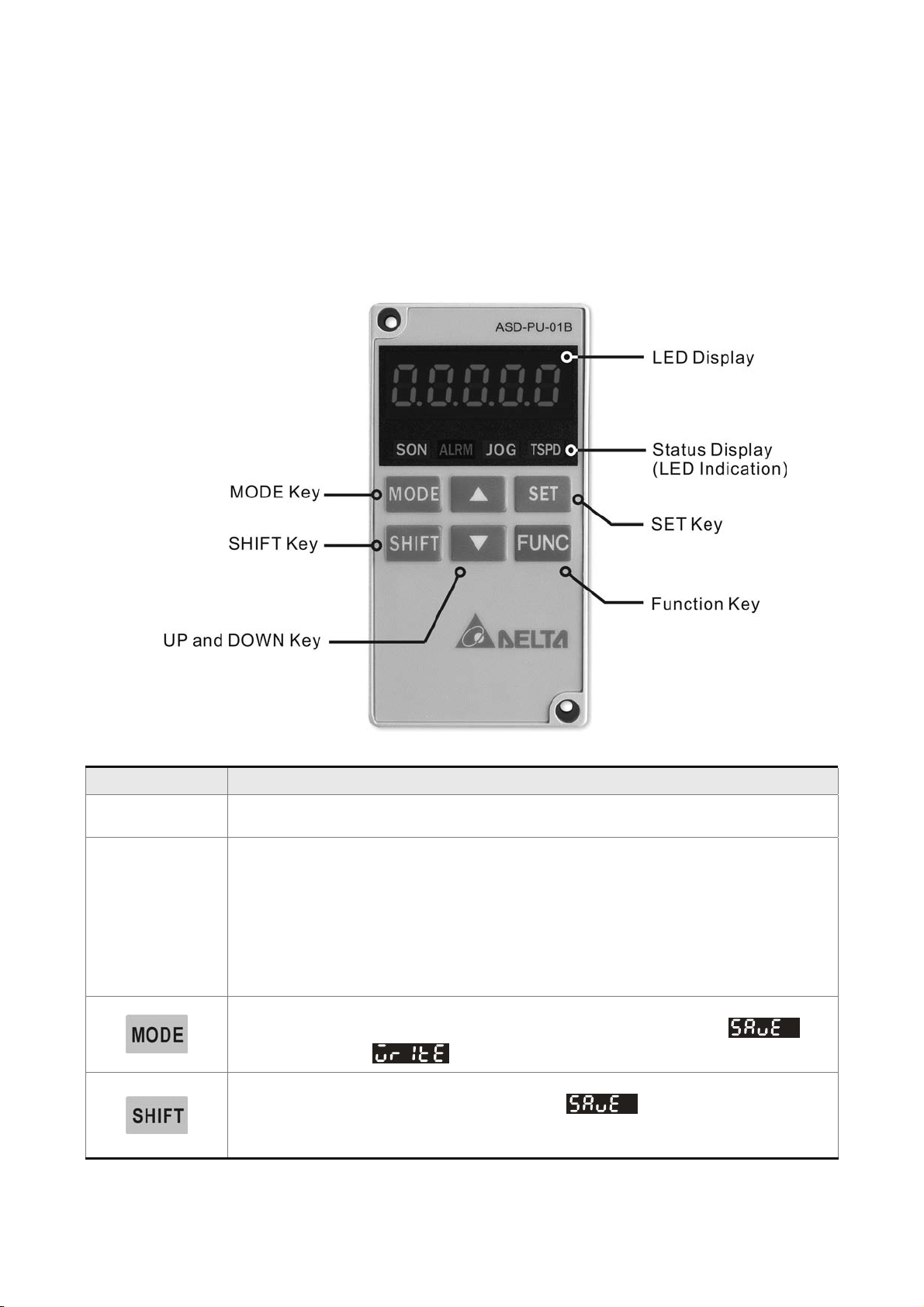
Chapter 4 Display and Operation|ASDA-B Series
4.2 ASD-PU-01B
4.2.1 Description of Digital Keypad ASD-PU-01B
The digital keypad includes the ASD-PU-01B display panel and function keys. The Figure 4.8 shows all
of the features of the ASD-PU-01B digital keypad and an overview of their functions.
Figure 4.8
Name Function
LED Display
Status Display
(LED Indication)
5-digit LED display shows the monitor codes, parameter settings and operation values
of the AC servo drive.
SON LED (Servo On Indicator). A lit LED illuminates to indicate that the servo drive is
enabled.
ALRM LED (Alarm Output Indicator). A lit ALRM LED illuminates to indicates that a
alarm output is activated.
JOG LED (JOG Operation Indicator). A lit JOG LED illuminates to indicates that JOG
operation is enabled.
TSPD LED (Speed reached Indicator). A lit TSPD LED illuminates to indicates that the
target speed is reached and TSPD signal is activated.
MODE Key. Pressing MODE key can enter or exit different parameter groups, and
switch between Parameter mode and Parameter Setting mode, SAVE (
mode and WRITE (
SHIFT Key. In Parameter mode, pressing SHIFT key can scrolls through parameter
groups. In Parameter Setting mode and SAVE (
selected and its value displayed, pressing SHIFT key can move the cursor to the left
and then change parameter settings (blinking digits) by using arrow keys.
) mode.
)
) mode, after a parameter is
4-18 Revision January 2009
Page 74

Chapter 4 Display and Operation|ASDA-B Series
Name Function
UP and DOWN arrow Key. Pressing the UP and DOWN arrow key can scroll through
and change monitor codes, parameter groups and various parameter settings.
In SAVE (
arrow key can scroll through and change the memory blocks. In SAVE mode, pressing
UP and DOWN arrow key can select and change the memory file name also.
SET Key. Pressing SET key can enter into the Parameter Setting mode, then display,
select and save parameter groups and various parameter settings. During diagnosis
operation, pressing SET key can execute the function in the last step.
(The parameter settings changes are not effective until the SET key is pressed.)
Function Key. Pressing Function key can enable JOG, Reset, Parameter Read &
Write, Fast Editing, Static Auto-tuning and Dynamic Auto-tuning these functions.
) mode and WRITE ( ) mode, pressing UP and DOWN
4.2.2 Display Flowchart
Monitor Mode, Parameter Mode and Parameter Setting Mode
1. When the power is applied to the AC servo drive, the digital keypad will execute communication
initial setup for approximately two seconds (9600bps & 7,N,2 Modbus ASCII) first, and then enter
into the monitor mode.
2. In monitor mode, pressing UP or DOWN arrow key can switch monitor parameter code.
3. In monitor mode, pressing MODE key can enter into parameter mode, pressing the SHIFT key
can switch parameter group and pressing UP or DOWN arrow key can change parameter group
code.
4. In parameter mode, system will enter into the parameter setting mode immediately after the SET
key is pressed. The LED display will display the corresponding setting value of this parameter
simultaneously. Then, users can use UP or DOWN arrow key to change parameter value or press
MODE key to exit and return back to the parameter mode.
5. In parameter setting mode, users can move the cursor to left by pressing the SHIFT key and
change the parameter settings (blinking digits) by pressing the UP or DOWN arrow key.
6. After the setting value change is completed, press SET key to save parameter settings or execute
command.
7. When the parameter setting is completed, LED display will show the end code “-END-“ and
automatically return back to parameter mode.
Revision January 2009 4-19
Page 75

Chapter 4 Display and Operation|ASDA-B Series
Figure 4.9
4-20 Revision January 2009
Page 76

Chapter 4 Display and Operation|ASDA-B Series
SAVE Mode ( Save parameter settings from the Drive to the Keypad)
1. When the power is applied to the AC servo drive, the digital keypad will enter into the monitor
mode first.
2. In monitor mode, pressing FUNC key first. Then, pressing UP key four times or DOWN key
three times can switch to SAVE mode.
3. In SAVE mode, pressing UP and DOWN key can save the desired memory block that the users
want to save.
4. If the desired memory block has not been used, the LED display will show the message “00000”
or “10000” or “20000” or “30000”, etc. If the desired memory block has been used and there are
parameters data saved in it, the LED display will show the MCU version of the servo drive and
the preset file name. For example, if the MCU version is 1.014, the message “01014” or “11014”
or “21014” or “31014”, etc. will show on the LED display. The users can change the save
address (memory block) by using UP and DOWN keys.
5. After the save address (memory block) is selected, press FUNC key, the LED display will show
. At this time, pressing MODE key once can return to the previous display, pressing
FUNC key can record the address and save the data. When recording the address, the LED
display will show
. After the address is saved to the keypad, the LED display will
show “0XXXX” (such as “01012” shown in Figure 4.10 on next page).
6. In SAVE mode, pressing MODE key once can return to the previous display and finally exit the
SAVE mode. However, if the users have pressed the FUNC key and enter into SAVE mode, i.e.
the SAVE operation has been executed, the MODE key will become disabled, and the users
cannot return to previous display and only can move to the next step.
7. The users can save the parameters in some memory block repeatedly on the condition that the
version, inertia and models of the servo drives should be the same. If one of the parameters is
set by the servo drive in different condition, it cannot be saved into the same memory block with
other parameters and must be saved to other memory blocks. Before re-using the same
memory block, please perform the “Memory Block Clear” function first (Please see the
description of parameter P8-11).
Revision January 2009 4-21
Page 77
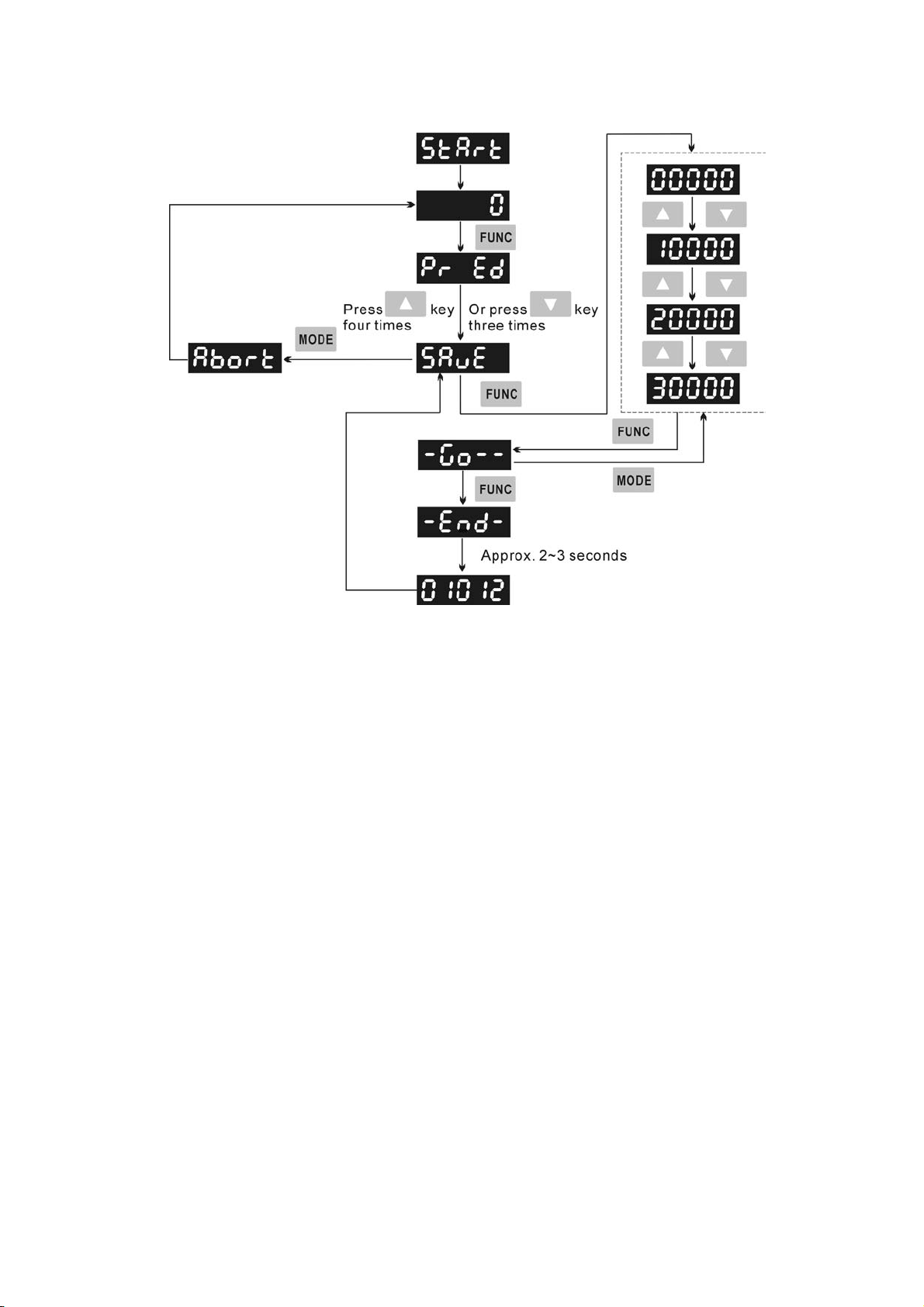
Chapter 4 Display and Operation|ASDA-B Series
Figure 4.10
4-22 Revision January 2009
Page 78
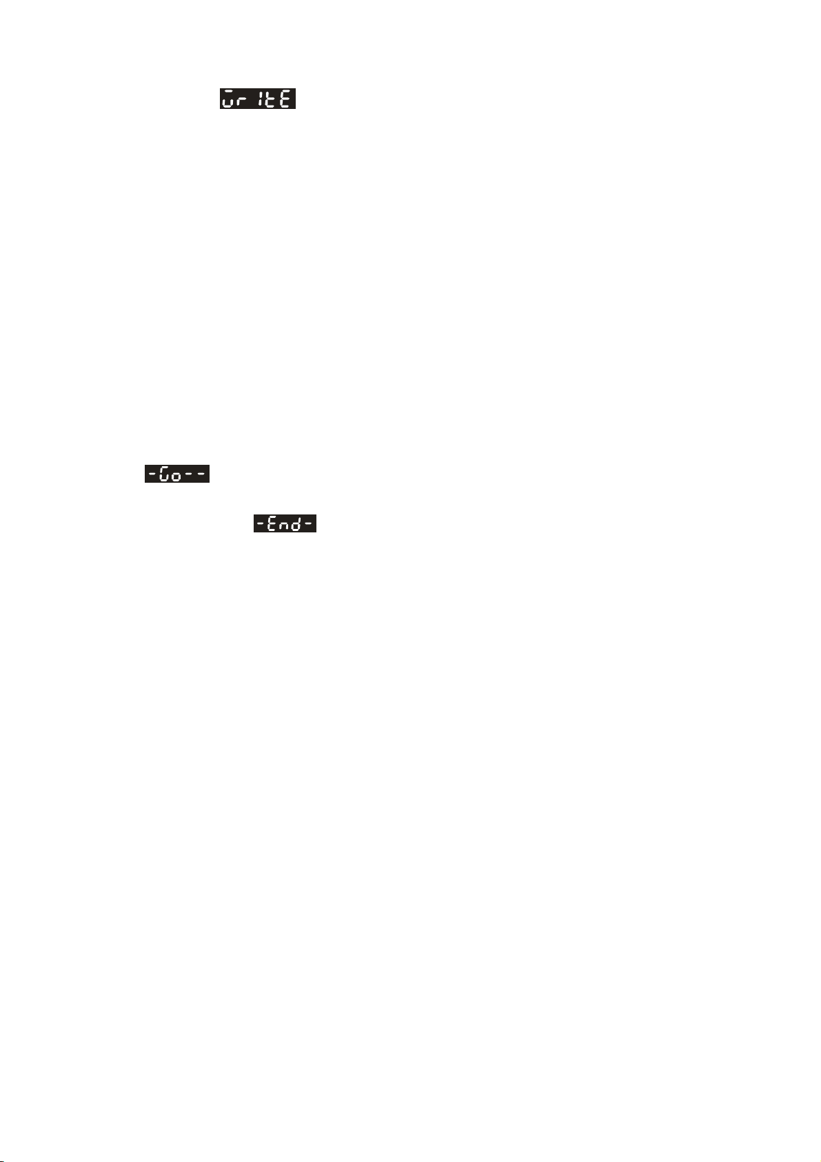
Chapter 4 Display and Operation|ASDA-B Series
WRITE Mode ( Parameter settings written out from Keypad to the Drive)
1. When the power is applied to the AC servo drive, the digital keypad will enter into the monitor
mode first.
2. In monitor mode, pressing FUNC key first. Then, pressing UP key five times or DOWN key two
times can switch to WRITE mode.
3. In WRITE mode, pressing UP and DOWN key can write out the desired memory block that the
users want to write out.
4. If the desired memory block has not been used, the LED display will show the message “00000”
or “10000” or “20000” or “30000”, etc. If the desired memory block has been used, the LED
display will show the MCU version of the servo drive and the preset file name. For example, if
the MCU version is 1.014, the message “01014” or “11014” or “21014” or “31014”, etc. will show
on the LED display. The users can change the write address (memory block) by using UP and
DOWN keys.
5. After the write address (memory block) is selected, press FUNC key, the LED display will show
. At this time, pressing MODE key once can return to the previous display, pressing
FUNC key can record the address and write out the data. When recording the address, the LED
display will show
. After the address is written, the LED display will show “0XXXX”
(such as “01012” shown in Figure 4.11 on next page).
6. In WRITE mode, pressing MODE key once can return to the previous display and finally exit the
WRITE mode.
7. Only the parameters of the same version, the same inertia and the same model type of the
servo drives can be written out. If the servo drive version stored in the keypad is different than
the actual servo drive version, the users can make them the same via Delta Servo Drive PC
software, ASDAB_SW.
Revision January 2009 4-23
Page 79
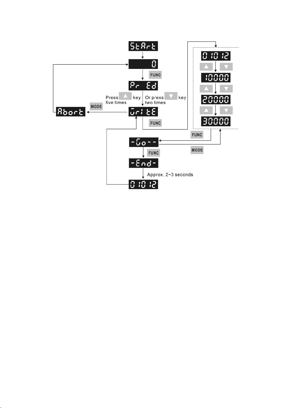
Chapter 4 Display and Operation|ASDA-B Series
Figure 4.11
4-24 Revision January 2009
Page 80

Chapter 4 Display and Operation|ASDA-B Series
Fast Edit Mode ( Fast Editing Function)
1. When the power is applied to the AC servo drive, the digital keypad will enter into the monitor
mode first.
2. In monitor mode, pressing FUNC key once can switch to Fast Edit mode.
3. In Fast Edit mode, pressing FUNC key can enable and disable Fast Editing function. When
display on the LED display, it indicates Fast Editing function is enabled. When
display on the LED display, it indicates Fast Editing function is disabled.
4. In Fast Edit mode, the users can enable or disable the Fast Editing function and browse through
the parameters that have been edited before.
5. In Fast Edit mode, when Static Auto-tuning function is enabled, the users can input the value of
responsiveness (frequency width), motor load inertia and stiffness directly.
6. In Fast Edit mode, when Dynamic Auto-tuning function is enabled, the users can input the value
of motor rotation number, motor rotation frequency, motor rotation time and responsiveness
directly.
7. Static Auto-tuning function only can be enabled in Manual mode (P2-32 is set to 0). If it is
enabled in AutoMode, an error message may display.
8. Dynamic Auto-tuning function only can be enabled in AutoMode (P2-32 is set to 1 or 2). If the
users want to use the Dynamic Auto-tuning function in Manual mode, please press MODE key
to skip the fourth step, which is the step used to specify the responsiveness.
9. In Fast Edit mode, pressing MODE key once can return to the previous display and finally exit
the Fast Edit mode (Please see Figure 4.12 below).
Figure 4.12
Revision January 2009 4-25
Page 81

Chapter 4 Display and Operation|ASDA-B Series
Dynamic Auto-tuning Mode ( Dynamic Auto-tuning Function)
1. When the power is applied to the AC servo drive, the digital keypad will enter into the monitor
mode first.
2. In monitor mode, pressing FUNC key first. Then, pressing UP key two times or DOWN key five
times can switch to Dynamic Auto-tuning mode.
3. In Dynamic Auto-tuning mode, the users can input the value of motor rotation number, motor
rotation frequency, motor rotation time and responsiveness directly.
4. Dynamic Auto-tuning function only can be enabled in AutoMode (P2-32 is set to 1 or 2). If the
users want to use the Dynamic Auto-tuning function in Manual mode, please press MODE key
to skip the fourth step, which is the step used to specify the responsiveness.
5. In Fast Edit mode, pressing MODE key once can return to the previous display and finally exit
the Fast Edit mode (Please see Figure 4.13 below).
Figure 4.13
4-26 Revision January 2009
Page 82

Chapter 4 Display and Operation|ASDA-B Series
Static Auto-tuning Mode ( Static Auto-tuning Function)
1. When the power is applied to the AC servo drive, the digital keypad will enter into the monitor
mode first.
2. In monitor mode, pressing FUNC key first. Then, pressing UP key two times or DOWN key five
times can switch to Static Auto-tuning mode.
3. In Static Auto-tuning mode, the users can input the value of responsiveness (frequency width),
motor load inertia and stiffness directly.
4. Static Auto-tuning function only can be enabled in Manual mode (P2-32 is set to 0). If it is
enabled in AutoMode, an error message may display.
5. In Fast Edit mode, pressing MODE key once can return to the previous display and finally exit
the Fast Edit mode (Please see Figure 4.14 below).
Figure 4.14
Revision January 2009 4-27
Page 83

Chapter 4 Display and Operation|ASDA-B Series
4.2.3 Status Display
Save Setting Display
After the SET key is pressed, LED display will show the following display messages for approx. one
second according to different status.
Display Message Description
The setting value is saved correctly.
This parameter is read only. Write-protected. (cannot be changed)
Invalid password or no password was input.
The setting value is error or input reserve setting value.
Abort Setting Display
Display Message Description
Fault Message Display
Display Message Description
Polarity Setting Display
Display Message Description
The servo module is enabled and this parameter cannot be
changed.
In parameter mode, pressing MODE key can abort parameter
setting change and return to monitor mode. In parameter setting
mode, pressing MODE key can return back to parameter mode.
After returning back to parameter mode, pressing MODE key
again can abort parameter setting change.
When the AC servo drive has a fault, LED display will display
“ALEnn”. “ALE” indicates the alarm and “nn” indicates the drive
fault code. The display range of alarm code “nn” is 1 to 48. For the
list of drive fault code, please refer to parameter P0-01 or refer to
Chapter 10 (Troubleshooting).
Positive value display. When entering into parameter setting
mode, pressing UP or DOWN arrow key can increase or decrease
the display value. SHIFT key is used to change the selected digit
(The selected digit will blink).
Negative value display. When the parameter setting is greater
than five digits, after the display value is set, continuously press
SHIFT key for six times and then the negative sign will show up to
indicate a negative value.
4-28 Revision January 2009
Page 84

Chapter 4 Display and Operation|ASDA-B Series
Monitor Setting Display
In monitor mode, in order to change the monitor status, the users can press UP or DOWN arrow key or
change parameter P0-02 directly to specify the monitor status. When the power is applied, the monitor
status depends on the setting value of P0-02. For example, if the setting value of P0-02 is 2 when the
power is applied, the monitor function will be “Pulse counts of pulse command”, the C.P monitor codes
will first display and then the pulse number will display after.
P0-02
Setting
0
1
2
3
4
5
6
Display Message Description Unit
Motor feedback pulse number pulse
Motor feedback rotation number rev
Pulse counts of pulse command pulse
Rotation number of pulse command rev
Position error counts pulse
Input frequency of pulse command kHz
Motor rotation speed rpm
7
8
9
10
11
12
13
Speed input command volt
Speed input command rpm
Torque input command volt
Torque input command Nt-m
Average load %
Peak load %
Main circuit voltage volt
Revision January 2009 4-29
Page 85

Chapter 4 Display and Operation|ASDA-B Series
P0-02
Setting
14
Display Message Description Unit
Ratio of load inertia to Motor inertia time
15
IGBT Temperature of power supply
module
The following table lists the display examples of monitor value:
Display Message Description
Positive value display.
Display value: +3000.
Negative value display.
Display value: -3000。
Decimal point display.
Display value: 5.00.
degC(°C)
4-30 Revision January 2009
Page 86

Chapter 4 Display and Operation|ASDA-B Series
4.2.4 Fault Code Display Operation
After entering the parameter mode P4-00 to P4-04 (Fault Record), press SET key to display the
corresponding fault code history for the parameter or press UP arrow key to display the fault code of H1
to H5 in order. H1 indicates the most recent occurred fault code, H2 is the previous occurred fault code
before H1 and so on.
Figure 4.15
4.2.5 JOG Operation
After entering parameter mode P4-05, the users can follow the following steps to perform JOG operation
or press FUNC key on the digital keypad to enter into JOG mode (parameter setting mode of P4-05)
directly.
Step 1 Press the FUNC key to display the JOG rpm speed. (The default value is 20 rpm).
Step 2 Press the UP or DOWN arrow keys to increase or decrease the desired JOG speed. (This also
can be undertaken by using the SHIFT key to move the cursor to the desired unit column (the
effected number will flash) then changed using the UP and DOWN arrow keys. The example
display in Figure 4.16 is adjusted as 21rpm.)
Step 3 Press the SET key when the desired JOG speed is set. The Servo Drive will display
and JOG LED will light up.
Step 4 Press the UP or DOWN arrow keys to jog the motor either CCW or CW. The motor will only
rotate while the arrow key is activated.
Step 5 To change JOG speed again, press the MODE key. After JOG speed is changed, press the
SET key and the JOG operation will run again. Refer back to #2 and #3 to change speed.
Revision January 2009 4-31
Page 87

Chapter 4 Display and Operation|ASDA-B Series
NOTE
1) JOG operation is effective only when Servo On (when the servo drive is enabled).
2) Before using JOG function, please ensure to confirm that P2-10 (DI1) is set to 101 (Servo On).
Otherwise, the JOG operation cannot be enabled even if the FUNC key has been pressed.
3) The users can set the acceleration and deceleration time in advance (the settings of parameter P1-
34, P1-35 and P1-36).
Figure 4.16
4-32 Revision January 2009
Page 88

Chapter 4 Display and Operation|ASDA-B Series
4.2.6 DO Force Output Diagnosis Operation
For testing, the digital outputs can be forced to be activated (ON) or inactivated (OFF) by using
parameter P4-06. Follow the setting method in Figure 4.17 to enter into DO force output diagnosis
operation (OP x) mode (“x” indicates the parameter range from 0 to 7). Pressing UP or DOWN arrow
key can change “x” value from 0 to 7 (hexadecimal format) and force digital outputs DO1 to DO3 to be
activated (ON) or inactivated (OFF). The DO function and status is determined by P2-18 to P2-20. This
function is enabled only when Servo Off (the servo drive is disabled).
Figure 4.17
Revision January 2009 4-33
Page 89
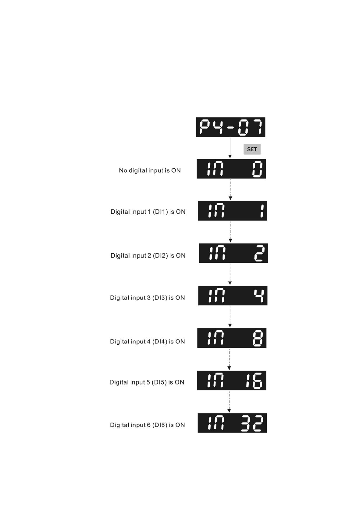
Chapter 4 Display and Operation|ASDA-B Series
4.2.7 DI Diagnosis Operation
Following the setting method in Figure 4.18 can perform DI diagnosis operation (parameter P4-07).
According to the ON and OFF status of the digital inputs DI1 to DI6, the corresponding status will
display on the servo drive LED display. When the segment lit and display on the screen, it means that
the corresponding digital input signal is ON.
Figure 4.18
4-34 Revision January 2009
Page 90

Chapter 4 Display and Operation|ASDA-B Series
4.2.8 DO Diagnosis Operation
Following the setting method in Figure 4.19 can perform DO diagnosis operation (parameter P4-09).
According to the ON and OFF status of the digital outputs DO1 to DO3, the corresponding status will
display on the servo drive LED display. When the segment lit and display on the screen, it means that
the corresponding digital input signal is ON.
Figure 4.19
Revision January 2009 4-35
Page 91
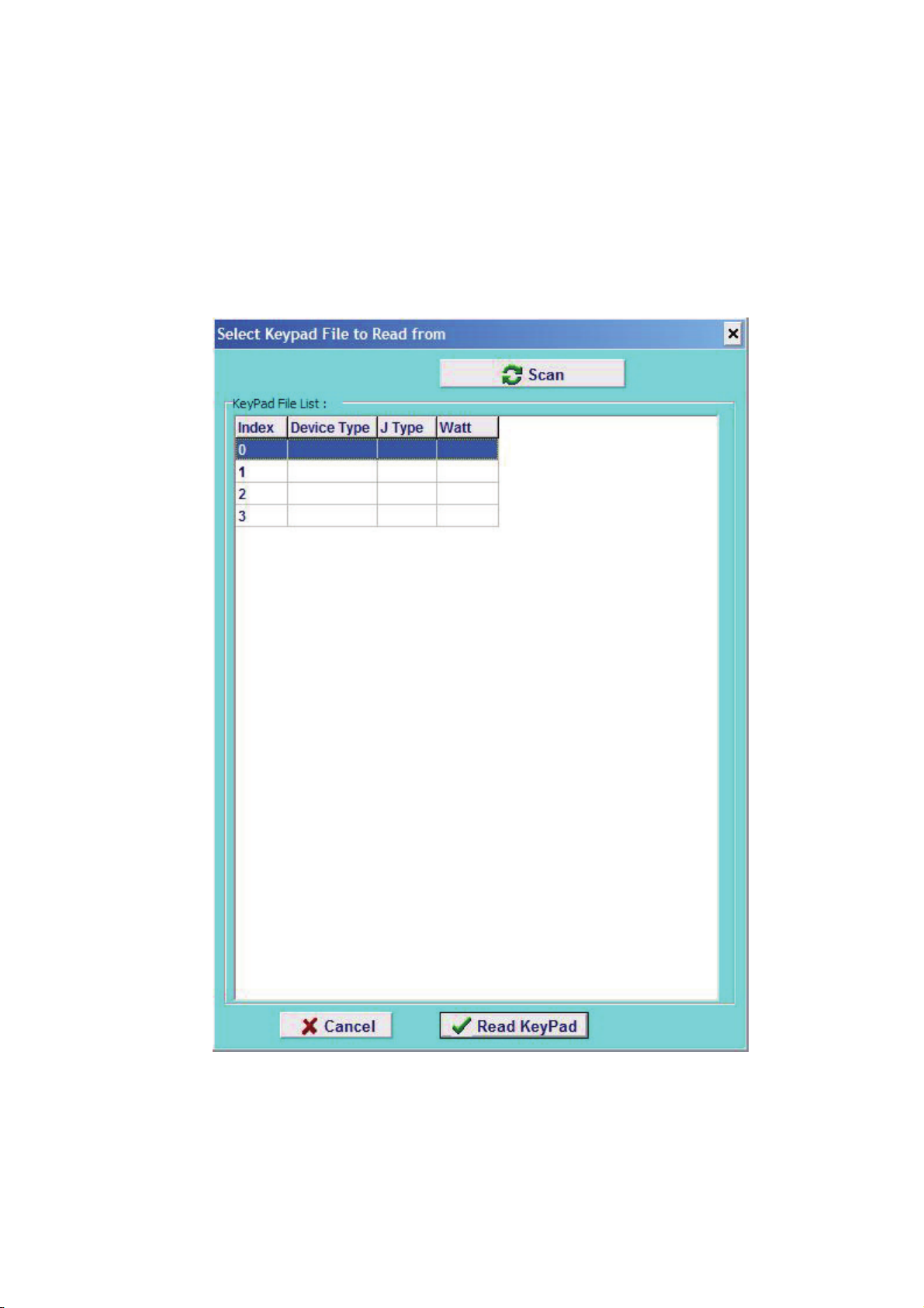
Chapter 4 Display and Operation|ASDA-B Series
4.2.9 Parameters Read and Write
Digital keypad provides the servo parameters read and write function not only for the servo drive but
also for PC side. The function of parameter read and write must be set via the PC software (Please see
Figure 4.20 & Figure 4.21). The users can use this software to read, write and manage all parameters.
When using this software to read and write parameters, the communication method of keypad
parameter P8-01 must be set to 0.
Figure 4.20
4-36 Revision January 2009
Page 92

Figure 4.21
Chapter 4 Display and Operation|ASDA-B Series
Revision January 2009 4-37
Page 93

Chapter 4 Display and Operation|ASDA-B Series
This page intentionally left blank.
4-38 Revision January 2009
Page 94

Chapter 5 Trial Run and Tuning Procedure
This chapter describes trial run and tuning procedure for servo drive and motor. Trial run, which is divided
into two parts, one part is to introduce the trial run without load, and the other part is to introduce trial run with
load. Ensure to complete the trial run without load first before performing the trial run with load. Tuning
procedure includes the tuning process, flowchart, and the relevant parameters of AutoMode (PI & PDFF)
mode and Manual mode
5.1 Inspection without Load
In order to prevent accidents and avoid damaging the servo drive and mechanical system, the trial run
should be performed under no load condition (no load connected, including disconnecting all couplings and
belts). Do not run servo motor while it is connected to load or mechanical system because the unassembled
parts on motor shaft may easily disassemble during running and it may damage mechanical system or even
result in personnel injury. After removing the load or mechanical system from the servo motor, if the servo
motor can runs normally following up the normal operation procedure (when trial run without load is
completed), then user can connect to the load and mechanical system to run the servo motor.
¾ In order to prevent accidents, the initial trial run for servo motor should be conducted under no load conditions
(separate the motor from its couplings and belts).
¾ Caution: Please perform trial run without load first and then perform trial run with load connected. After the
servo motor is running normally and regularly without load, then run servo motor with load connected. Ensure
to perform trial run in this order to prevent unnecessary danger.
After power in connected to AC servo drive, the charge LED will light and it indicates that AC servo drive is
ready. Please check the followings before trial run in order to find the problem and correct it in advance.
Doing this can avoid the damage to the servo drive and servo motor.
Item Content
z Inspect the servo drive and servo motor to insure they were not damaged.
z To avoid an electric shock, be sure to connect the ground terminal of servo drive
to the ground terminal of control panel.
z Before making any connection, wait 10 minutes for capacitors to discharge after
the power is disconnected, alternatively, use an appropriate discharge device to
discharge.
z Ensure that all wiring terminals are correctly insulated.
Inspection before
operation
(Control power is not
applied)
z Ensure that all wiring is correct or damage and or malfunction may result.
z Visually check to ensure that there are not any unused screws, metal strips, or
any conductive or inflammable materials inside the drive.
z Never put inflammable objects on servo drive or close to the external
regenerative resistor.
z Make sure control switch is OFF.
z If the electromagnetic brake is being used, ensure that it is correctly wired.
z If required, use an appropriate electrical filter to eliminate noise to the servo drive.
z Ensure that the external applied voltage to the drive is correct and matched to the
controller.
Revision January 2009 5-1
Page 95

Chapter 5 Trial Run and Tuning Procedure|ASDA-B Series
Item Content
z Ensure that the cables are not damaged, stressed excessively or loaded heavily.
When the motor is running, pay close attention on the connection of the cables
and notice that if they are damaged, frayed or over extended.
z Check for abnormal vibrations and sounds during operation. If the servo motor is
vibrating or there are unusual noises while the motor is running, please contact
the dealer or manufacturer for assistance.
z Ensure that all user-defined parameters are set correctly. Since the
Inspection during
operation
(Control power is
applied))
characteristics of various machinery are different, in order to avoid accident or
cause damage, do not adjust the parameter abnormally and ensure the
parameter setting is not an excessive value.
z Ensure to reset some parameters when the servo drive is off (Please refer to
Chapter 7). Otherwise, it may result in malfunction.
z If there is no contact sound or there be any unusual noises when the relay of the
servo drive is operating, please contact your distributor for assistance or contact
with Delta.
z Check for abnormal conditions of the power indicators and LED display. If there is
any abnormal condition of the power indicators and LED display, please contact
your distributor for assistance or contact with Delta.
5-2 Revision January 2009
Page 96

Chapter 5 Trial Run and Tuning Procedure|ASDA-B Series
5.2 Applying Power to the Drive
Users please observe the following steps when applying power supply to the servo drive.
1. Please check and confirm the wiring connection between the drive and motor is correct.
1) Terminal U, V, W and FG (frame ground) must connect to Red, White, Black and Green cables
separately (U: Red, V: White, W: Black, FG: Green). If not connect to the specified cable and
terminal, then the drive cannot control motor. The motor grounding lead, FG must connect to
grounding terminal. For more information of cables, please refer to section 3.1.
2) Ensure to connect encoder cable to CN2 connector correctly. If users only desire to execute JOG
operation, it is not necessary to make any connection to CN1 and CN3 connector. For more
information of the connection of CN2 connector, please refer to Section 3.1 and 3.4.
¾ Do not connect the AC input power (R, S, T) to the (U, V, W) output terminals. This will damage the AC servo
drive.
2. Main circuit wiring
Connect power to the AC servo. For three-phase input power connection and single-phase input power
connection, please refer to Section 3.1.3.
3. Turn the Power On
The servo power is main circuit power (R, S, T). When the power is on, the AC servo drive will start many
items of self-test. After the test, if
result is normal. If there is any text or value displayed on the display, please refer to parameter P0-01
(Drive Fault Code) to know the fault message and refer to Chapter 10 (Troubleshooting) to clear or
remove the fault.
1) When display shows:
displays and blinks on the LCD display, it indicates that the testing
Over voltage:
The main circuit voltage has exceeded its maximum allowable value or input power is error (Incorrect
power input).
Corrective Actions:
Use voltmeter to check whether the input voltage falls within the rated input voltage.
Use voltmeter to check whether the input voltage is within the specified limit.
Revision January 2009 5-3
Page 97

Chapter 5 Trial Run and Tuning Procedure|ASDA-B Series
2) When display shows:
Encoder error:
Check if the wiring is correct. Check if the encoder wiring (CN2) of servo motor is loose or incorrect.
Corrective Actions:
Check if the user performs wiring recommended in the user manual.
Examine the encoder connector and cable.
Inspect whether wire is loose or not.
Check if the encoder is damaged.
3) When display shows:
Emergency stop activated:
Please check if any of digital inputs DI1~DI6 signal is set to “Emergency Stop” (EMGS).
Corrective Actions:
If it does not need to use “Emergency Stop (EMGS)” as input signal, the users only need to
confirm that if all of the digital inputs DI1~DI6 are not set to “Emergency Stop (EMGS)”. (The
setting value of parameter P2-10 to P2-15 is not set to 21.)
If it is necessary to use “Emergency Stop (EMGS)” as input signal, the users only need to
confirm that which of digital inputs DI1~DI6 is set to “Emergency Stop (EMGS)” and check if
the digital input signal is ON (It should be activated).
4) When display shows:
Reverse limit switch error:
Please check if any of digital inputs DI1~DI6 signal is set to “Reverse inhibit limit (CWL)” and check if
the signal is ON or not.
Corrective Actions:
If it does not need to use “Reverse inhibit limit (CWL)” as input signal, the users only need to
confirm that if all of the digital inputs DI1~DI6 are not set to “Reverse inhibit limit (CWL)”. (The
setting value of parameter P2-10 to P2-15 is not set to 22.)
If it is necessary to use “Reverse inhibit limit (CWL)” as input signal, the users only need to
confirm that which of digital inputs DI1~DI6 is set to “Reverse inhibit limit (CWL)” and check if
the digital input signal is ON (It should be activated).
5-4 Revision January 2009
Page 98

Chapter 5 Trial Run and Tuning Procedure|ASDA-B Series
5) When display shows:
Forward limit switch error:
Please check if any of digital inputs DI1~DI6 signal is set to “Forward inhibit limit (CCWL)” and check if
the signal is ON or not.
Corrective Actions:
If it is no need to use “Forward inhibit limit (CCWL)” as input signal, the users only need to
confirm that if all of the digital inputs DI1~DI8 are not set to “Forward inhibit limit (CCWL)”. (The
setting value of parameter P2-10 to P2-15 is not set to 23.)
If it is necessary to use “Forward inhibit limit (CCWL)” as input signal, the users only need to
confirm that which of digital inputs DI1~DI6 is set to “Forward inhibit limit (CCWL)” and check if
the digital input signal is ON (It should be activated).
When “Digital Input 1 (DI1)” is set to Servo On (SON), if DI1 is set to ON (it indicates that Servo On
(SON) function is enabled) and the following fault message shows on the display:
6) When display shows:
Overcurrent:
Corrective Actions:
Check the wiring connections between the servo drive and motor.
Check if the circuit of the wiring is closed.
Remove the short-circuited condition and avoid metal conductor being exposed.
7) When display shows:
Undervoltage:
Corrective Actions:
Check whether the wiring of main circuit input voltage is normal.
Use voltmeter to check whether input voltage of main circuit is normal.
Use voltmeter to check whether the input voltage is within the specified specification.
8) When display shows:
Revision January 2009 5-5
Page 99

Chapter 5 Trial Run and Tuning Procedure|ASDA-B Series
Magnetic field error:
Corrective Actions:
Check if the encoder is abnormal.
Verify the encoder connector.
9) When display shows:
Input power phase loss:
Corrective Actions:
Verify the main circuit power R, S, T. Check for possible poor connection on the power cable.
Check if one phase of the input power is lost.
NOTE
1) If there are any unknown fault codes and abnormal display when applying power to the drive or servo on
is activated (without giving any command), please inform the distributor or contact with Delta for
assistance.
5-6 Revision January 2009
Page 100

Chapter 5 Trial Run and Tuning Procedure|ASDA-B Series
5.3 JOG Trial Run without Load
It is very convenient to use JOG trial run without load to test the servo drive and motor as it can save the
wiring. The external wiring is not necessary and the users only need to connect the digital keypad (ASD-PU-
01A or ASD-PU-01B) to the servo drive. For safety, it is recommended to set JOG speed at low speed.
Please refer to the following steps to perform JOG trial run without load.
5.3.1 ASD-PU-01A Tuning Flowchart
STEP 1: Turn the drive ON through software. Ensure that there is no fault message display on the LCD
display and the servo drive is normal.
STEP 2: Press JOG key on the keypad and the drive will enter into JOG operation mode automatically.
(At this time, the servo drive is enabled (Servo On).)
STEP 3: The users can press UP and DOWN key to change JOG speed and press SHIFT key to adjust
the digit number of the displayed value.
STEP 4: Pressing SET key can determine the speed of JOG operation.
STEP 5: Pressing UP key and the servo motor will run in CCW direction. After releasing UP key, the
motor will stop running.
STEP 6: Pressing DOWN key and the servo motor will run in CW direction. After releasing DOWN key,
the motor will stop running.
CW and CCW Definition:
CCW (Counterclockwise): when facing the servo motor shaft, CCW is reverse running.
CW (Clockwise): when facing the servo motor shaft, CW is forward running.
STEP 7: When pressing MODE key, it can exit JOG operation mode.
NOTE
Please note that JOG operation cannot be used when EMGS occurs (ALE13, Emergency stop activated).
However, if CWL (ALE14, Reverse inhibit limit) or CCWL (ALE15, Forward inhibit limit) occurs during
JOG operation, the users can still use JOG operation without problem.
Please refer to the description of Section 4.1.5 in Chapter 4.
Revision January 2009 5-7
 Loading...