

ASDA A2-E
EtherCAT
Interface Servo Drive
User Manual
www.deltaww.com
ASDA A2-E
EtherCAT Interface Servo Drive User Manual
V3.0
DELTA_ASDA-A2-E_UM_EN_20150430
Industrial Automation Headquarters
Delta Electronics, Inc.
Taoyuan Technology Center
No.18, Xinglong Rd., Taoyuan City,
Taoyuan County 33068, Taiwan
TEL: 886-3-362-6301 / FAX: 886-3-371-6301
Asia
Delta Electronics (Jiangsu) Ltd.
Wujiang Plant 3
1688 Jiangxing East Road,
Wujiang Economic Development Zone
Wujiang City, Jiang Su Province, P.R.C. 215200
TEL: 86-512-6340-3008 / FAX: 86-769-6340-7290
Delta Greentech (China) Co., Ltd.
238 Min-Xia Road, Pudong District,
ShangHai, P.R.C. 201209
TEL: 86-21-58635678 / FAX: 86-21-58630003
Delta Electronics (Japan), Inc.
Tokyo Ofce
2-1-14 Minato-ku Shibadaimon,
Tokyo 105-0012, Japan
TEL: 81-3-5733-1111 / FAX: 81-3-5733-1211
Delta Electronics (Korea), Inc.
1511, Byucksan Digital Valley 6-cha, Gasan-dong,
Geumcheon-gu, Seoul, Korea, 153-704
TEL: 82-2-515-5303 / FAX: 82-2-515-5302
Delta Electronics Int’l (S) Pte Ltd.
4 Kaki Bukit Ave 1, #05-05, Singapore 417939
TEL: 65-6747-5155 / FAX: 65-6744-9228
Delta Electronics (India) Pvt. Ltd.
Plot No 43 Sector 35, HSIIDC
Gurgaon, PIN 122001, Haryana, India
TEL : 91-124-4874900 / FAX : 91-124-4874945
Americas
Delta Products Corporation (USA)
Raleigh Ofce
P.O. Box 12173,5101 Davis Drive,
Research Triangle Park, NC 27709, U.S.A.
TEL: 1-919-767-3800 / FAX: 1-919-767-8080
Delta Greentech (Brasil) S.A.
Sao Paulo Ofce
Rua Itapeva, 26 - 3° andar Edicio Itapeva One-Bela Vista
01332-000-São Paulo-SP-Brazil
TEL: 55 11 3568-3855 / FAX: 55 11 3568-3865
Europe
Deltronics (The Netherlands) B.V.
Eindhoven Ofce
De Witbogt 15, 5652 AG Eindhoven, The Netherlands
TEL: 31-40-2592850 / FAX: 31-40-2592851
*We reserve the right to change the information in this manual without prior notice.
Via Polesine, 1/4
10020 Cambiano ( TO ) Italy
+39 011 9454523
www.e-comtech.it
info@e-comtech.it

Revision April, 2015 i
Table of Contents
Chapter 1 CoE Drive Overview ................................................................................. 1-1
1.1 Communication Specification ...................................................................... 1-1
1.2 The Interface of Delta EtherCAT Servo Drive .............................................. 1-2
1.3 LED Indicators ............................................................................................. 1-3
1.4 The Topology ............................................................................................... 1-6
1.5 Wiring .......................................................................................................... 1-7
1.5.1 Explanation of I/O (CN1) Connector Signal ............................................ 1-8
1.5.2 CN2 Connector ....................................................................................... 1-9
1.5.3 CN5 Connector (Full-closed Loop) ......................................................... 1-10
1.5.4 CN6 EtherCAT Terminal ........................................................................ 1-11
1.5.5 CN7 Extension DI ................................................................................... 1-12
1.5.6 CN-STO.................................................................................................. 1-13
1.5.7 STO with Safety Relay ........................................................................... 1-14
1.5.8 STO Disable ........................................................................................... 1-14
1.6 Dimension .................................................................................................... 1-15
1.6.1 220V Series ............................................................................................ 1-15
1.6.2 400V Series ............................................................................................ 1-17
Chapter 2 System Setup ........................................................................................... 2-1
2.1 Parameter Settings of EtherCAT Mode ....................................................... 2-1
2.2 TwinCAT Setup ............................................................................................ 2-3
2.3 Synchronization Modes Setting ................................................................... 2-11

ASDA A2-E Table of Contents
ii Revision April, 2015
2.3.1 Two Synchronization Modes of Delta Servo ........................................... 2-11
2.3.2 Select the Synchronization Mode ........................................................... 2-12
2.3.3 Synchronous Clock Time Setting ........................................................... 2-12
2.4 PDO Mapping .............................................................................................. 2-14
2.4.1 Default PDO Mappings ........................................................................... 2-14
2.4.2 Re-define a PDO Mapping ..................................................................... 2-15
2.4.3 Using TwinCAT ...................................................................................... 2-16
Chapter 3 EtherCAT Communication States ........................................................... 3-1
3.1 State Transition Operation ........................................................................... 3-2
Chapter 4 EtherCAT Troubleshooting ..................................................................... 4-1
Chapter 5 CANopen Operation Mode ....................................................................... 5-1
5.1 Profile Position Mode ................................................................................... 5-1
5.1.1 Description ............................................................................................. 5-1
5.1.2 Operation Procedures ............................................................................ 5-1
5.1.3 Advanced Setting Procedures ................................................................ 5-2
5.1.4 Associated Object List ............................................................................ 5-3
5.2 Interpolation Position Mode ......................................................................... 5-4
5.2.1 Description ............................................................................................. 5-4
5.2.2 Operation Procedures ............................................................................ 5-5
5.2.3 Associated Object List ............................................................................ 5-5
5.3 Cyclic Synchronous Position Mode .............................................................. 5-6
5.3.1 Description ............................................................................................. 5-6

Table of Contents ASDA A2-E
Revision April, 2015 iii
5.3.2 The Function of CSP Mode .................................................................... 5-6
5.3.3 Operation Procedures ............................................................................ 5-6
5.3.4 Associated Object List ............................................................................ 5-7
5.4 Homing Mode .............................................................................................. 5-8
5.4.1 Description ............................................................................................. 5-8
5.4.2 Operation Procedures ............................................................................ 5-8
5.4.3 Associated Object List ............................................................................ 5-9
5.5 Profile Velocity Mode ................................................................................... 5-10
5.5.1 Description ............................................................................................. 5-10
5.5.2 Operation Procedures ............................................................................ 5-10
5.5.3 Advanced Setting Procedures ................................................................ 5-11
5.5.4 Associated Object List ............................................................................ 5-11
5.6 Cyclic Synchronous Velocity Mode .............................................................. 5-12
5.6.1 Description ............................................................................................. 5-12
5.6.2 The Function of CSV Mode .................................................................... 5-12
5.6.3 Operation Procedures ............................................................................ 5-12
5.6.4 Associated Object List ............................................................................ 5-13
5.7 Profile Torque Mode .................................................................................... 5-14
5.7.1 Description ............................................................................................. 5-14
5.7.2 Operation Procedures ............................................................................ 5-14
5.7.3 Advanced Setting Procedures ................................................................ 5-14
5.7.4 Associated Object List ............................................................................ 5-15
5.8 Cyclic Synchronous Torque Mode ............................................................... 5-16
5.8.1 Description ............................................................................................. 5-16
5.8.2 The Function of CST Mode .................................................................... 5-16

ASDA A2-E Table of Contents
iv Revision April, 2015
5.8.3 Operation Procedures ............................................................................ 5-16
5.8.4 Associated Object List ............................................................................ 5-17
5.9 Limit Position Handling Procedure ............................................................... 5-18
5.9.1 Description ............................................................................................. 5-18
5.9.2 Operation Procedures ............................................................................ 5-18
5.10 Touch Probe Function ................................................................................. 5-19
5.10.1 Description ............................................................................................. 5-19
5.10.2 Touch Probe Function ............................................................................ 5-19
5.10.3 Touch Probe Status ................................................................................ 5-20
5.10.4 Associated Object List ............................................................................ 5-21
Chapter 6 Object Dictionary Entries ........................................................................ 6-1
6.1 Specifications for Objects ............................................................................ 6-1
6.1.1 Object Type ............................................................................................ 6-1
6.1.2 Data Type ............................................................................................... 6-1
6.2 Overview of Object Group 1000h ................................................................. 6-2
6.3 Overview of Object Group 6000
h
................................................................. 6-3
6.4 Details of Objects ......................................................................................... 6-6
Chapter 7 Safety Function (Safe Torque Off, STO) ................................................. 7-1
7.1 Description of Terminal Block ...................................................................... 7-1
7.1.1 Functional Safety Standard and Certificates ........................................... 7-3
7.2 STO Safety Function ................................................................................... 7-3
7.3 Related Parameter Descriptions of STO Function ....................................... 7-5
7.4 Related Alarm Descriptions of STO Function .............................................. 7-6

Table of Contents ASDA A2-E
Revision April, 2015 v
Chapter 8 Alarm List .................................................................................................. 8-1
8.1 EtherCAT Communication Fault Messages ................................................. 8-1
8.2 Error Code Table ......................................................................................... 8-4
8.3 SDO Error Message Abort Codes ................................................................ 8-7
Chapter 9 Reference .................................................................................................. 9-1

ASDA A2-E Table of Contents
vi Revision April, 2015
(This page is intentionally left blank.)

Revision April, 2015 1-1
Chapter 1 CoE Drive Overview
1.1 Communication Specification
EtherCAT
Communication
Physical layer
100BASE-TX
Communication
connector
RJ45 × 2 (Connector CN6A=IN, CN6B=OUT)
Network topology
Line connection
Baud rate
2 x 100 Mbps (full duplex)
Frame data length
Maximum 1484 bytes
SyncManager
SM0: Mailbox output
SM1: Mailbox input
SM2: Process data output
SM3: Process data input
FMMU
(Fieldbus Memory
Management Units)
FMMU0: Process data output area
FMMU1: Process data input area
FMMU2: Mailbox status area
Device profile
CoE: CANopen over EtherCAT
Synchronization
mode
DC synchronization ( SYNC0 )
Non- synchronized ( Free Run )
Communication
object
SDO: Service Data Object
PDO: Process Data Object
EMCY: Emergency Data Object
LED indicator
(On RJ45
Connector)
EtherCAT ERR (ER) × 1
EtherCAT Link/Activity (L/A) × 2
EtherCAT RUN (RN) × 1
Application layer
specifications
IEC61800-7 CiA402 Drive Profile
The supported CiA402 operation
modes
Profile Position Mode (PP)
Profile Velocity Mode (PV)
Profile Torque Mode (PT)
Homing Mode (HM)
Interpolated Position Mode(IP)
Cycle Synchronized Position Mode (CSP)
Cycle Synchronized Velocity Mode (CSV)
Cycle Synchronized Torque Mode (CST)

ASDA A2-E Chapter 1 Coe Drive Overview
1-2 Revision April, 2015
1.2 The Interface of Delta EtherCAT Servo Drive
Figure 1 The Interface of Delta EtherCAT Servo Drive
EtherCAT® is registered trademark and patented technology, licensed by Beckhoff
Automation GmbH, Germany.
Run indicator (RUN)
Link/Activity of EtherCAT
output port indicator (L/A)
Error indicator (ERR)
EtherCAT output
port (CN6)
EtherCAT input port
(CN6)
Link/Activity of EtherCAT
input port indicator (L/A)
Chapter 1 CoE Drive Overview ASDA A2-E
Revision April, 2015 1-3
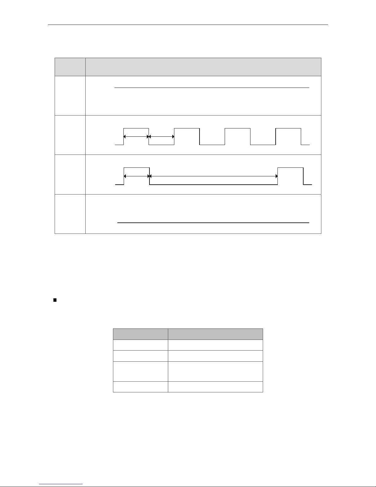
1.3 LED Indicators
Indicator
state
Indicator pattern
ON
ON
OFF
Blinking
ON
OFF
200ms
200ms
Single
Flash
ON
OFF
200ms
1000ms
OFF
ON
OFF
Figure 2. RJ45 LED indicator pattern
ERROR (ERR) LED
The ERR LED indicator shows the error status of EtherCAT communication.
Indicator state Slave State
Off No error
Blinking State change error
Single Flash
Synchronization error
SyncManager error
On PDI Watchdog timeout

ASDA A2-E Chapter 1 Coe Drive Overview
1-4 Revision April, 2015
State change error: The state machine does not allow the system to change its state
because the wrong parameter settings. Please refer to Figure 29 for
its switching conditions.
Synchronization error: The synchronization of Master Clock and Slave Clock is failed.
SyncManager error: The data of process data is lost when receiving.
PDI Watchdog
timeout:
The hardware failure on slave. Please contact Delta distributors for
assistance.
RUN LED
The RUN LED indicator shows the status of EtherCAT state machine
Indicator state Slave State
Off INIT
Blinking PRE-OPERATIONAL
Single Flash SAFE-OPERATIONAL
On OPERATIONAL
INIT: After power on, the EtherCAT slave will get into INIT state if there
is no error. At INIT state, no communication servo is provided.
Accessing slave’s register from the host is available at this state.
PRE-OPERATIONAL: The SDO can be used to communicate with its host controller.
SAVE-
OPERATIONAL:
Both SDO and TxPDO, which can send cyclic data from the slave
to the host, are workable.
OPERATIONAL: SDO, TxPDO and RxPDO are working.

Chapter 1 CoE Drive Overview ASDA A2-E
Revision April, 2015 1-5
Link Activity (L/A) LED
The L/A LED indicator shows the physical link status and the link activity.
Indicator state Slave State
Off No link
Blinking Link and activity
On Link without activity
No link: The link has not established yet.
Link and activity: The data is exchanging with its partners.
Link without activity: The link is established but no data is exchanging now.
ASDA A2-E Chapter 1 Coe Drive Overview
1-6 Revision April, 2015
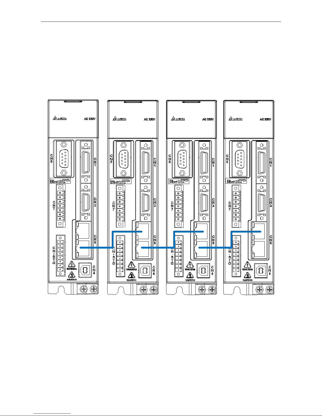
1.4 The Topology
The topology is defined by the host controller. Please refer to the host controller ’s
application manual. There are only one input port and one output port on Delta servo drive
for EtherCAT communication ports.
Figure 3 EtherCAT connection topology example
Chapter 1 CoE Drive Overview ASDA A2-E
Revision April, 2015 1-7
1.5 Wiring
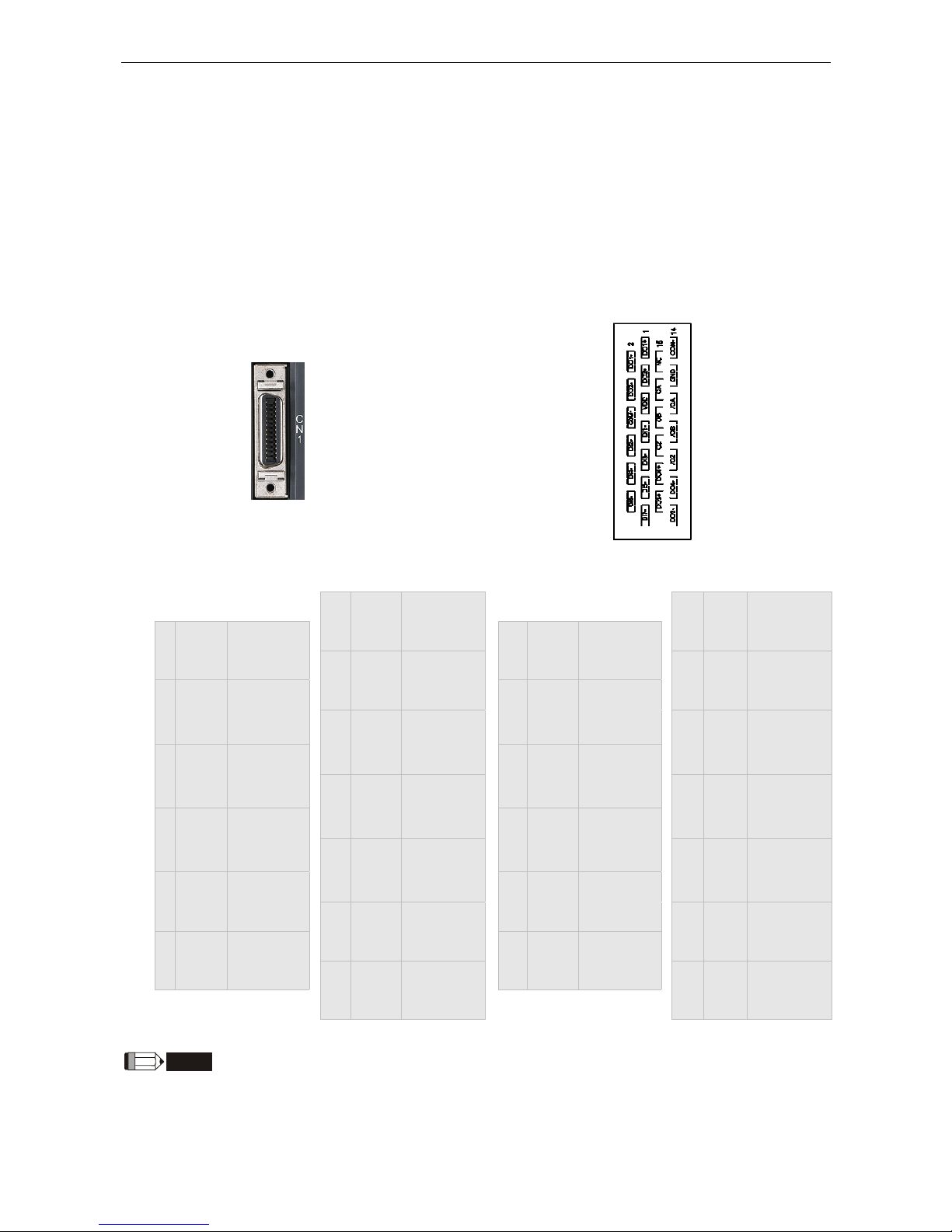
I/O Signal (CN1) Connection and Connector Terminal Layout
In order to have a more flexible communication with the master, 4 programmable
Digital Output (DO) and 7 programmable Digital Input (DI) are provided, which are
parameter P2-18~P2-21 and P2-10~P2-16 respectively. In addition, the differential
output encoder signal A+, A-, B+, B-, Z+ and Z- is also provided. The followings are
the pin diagrams.
CN1 Connector (female)
CN1 Connector (male)
rear view
1 DO1+
Digital
output
14 COM-
VDD power
ground
2 DO1-
Digital
output
15 NC N/A
3 DO2+
Digital
output
16 GND
Analog
input signal
ground
4 DO2-
Digital
output
17 OA
Encoder/
A pulse
output
5 VDD
+24V Power
output
18 /OA
Encoder/
A pulse
output
6 COM+
Power input
(12~24V)
19 OB
Encoder/
B pulse
output
7 DI1- Digital input
20 /OB
Encoder/
B pulse
output
8 DI2- Digital input
21 OZ
Encoder/
Z pulse
output
9 DI3- Digital input
22 /OZ
Encoder/
Z pulse
output
10 DI4- Digital input
23 DO4+
Digital
output
11 DI5- Digital input
24 DO4-
Digital
output
12 DI6- Digital input
25 DO3+
Digital
output
13 DI7- Digital input
26 DO3-
Digital
output
NOTE
NC means NO CONNECTION. This terminal is for internal use only. Do not connect it, or it may damage the
servo drive.

ASDA A2-E Chapter 1 Coe Drive Overview
1-8 Revision April, 2015
1.5.1 Explanation of I/O (CN1) Connector Signal
The following details the signals listed in previous section.
General Signals
Signal Name Pin No Function
Wiring
Method
(Refer to
3.4.3)
Position
pulse
(output)
OA
/OA
17
18
Encoder signal output A, B, Z (Line Driver output)
C13/C14
OB
/OB
19
20
OZ
/OZ
21
22
Power
VDD 5
VDD is the +24V power provided by the drive and
is for Digital Input (DI) and Digital Output (DO)
signal. The maximum current is 500mA.
-
COM+ 6
COM+ is the common input of Digital Input (DI)
and Digital Output (DO) voltage. When using
VDD, VDD should be connected to COM+. If not
using, it needs to apply the external power (+12V
~+24V). Its positive end should connect to COM+
and the negative end should connect to COM-.
COM- 14
GND 16
VCC voltage is based on GND.
Other NC 15
NO CONNECTION. This terminal is for internal
use only. Do not connect it, or it may damage the
servo drive.

Chapter 1 CoE Drive Overview ASDA A2-E
Revision April, 2015 1-9
1.5.2 CN2 Connector
CN2 Connector (female)
CN2 Connector (male)
Rear view
Quick Connector
HOUSING: AMP (1-172161-9)
Military Connector
3106A-20-29S
Drive Connector Motor Connector
Pin No
Terminal
Symbol
Function and Description
Military
connector
Quick
connector
Color
5 T+
Serial communication signal
input / output (+)
A 1 Blue
4 T-
Serial communication signal
input / output (-)
B 4
Blue &
Black
- -
Reserved - - -
- -
Reserved - - -
14,16 +5V
Power +5V S 7
Red/Red &
white
13,15 GND
Power ground R 8
Black/Black
& white
- -
shielding L 9 -

ASDA A2-E Chapter 1 Coe Drive Overview
1-10 Revision April, 2015
1.5.3 CN5 Connector (Full-closed Loop)
Connect linear scale or encoder (A, B, Z format) to the servo and form a full-closed
loop. In position mode, the pulse command issued by the controller is based on the
control loop of the external linear scale. Please refer to Chapter 6.
CN5 Connector (female)
Pin No Signal Name Terminal Symbol Function and Description
1 /Z phase input Opt_/Z /Z phase
2 /B phase input Opt_/B /B phase
3 B phase input Opt_B B phase
4 A phase input Opt_A A phase
5 /A phase input Opt_/A /A phase
6 Encoder grounding GND Ground
7 Encoder grounding GND Ground
8 Encoder power +5V + 5V power
9 Z phase input Opt_Z Z phase
NOTE
1. It only supports the encoder of AB phase and 5V voltage.
2. The application of full-closed loop: it supports the encoder of highest resolution 1280000 pulse/rev (A
pulse number per motor revolution for a full-closed loop that corresponds to an optical signal with AB
(Quadrature) phase pulses (4x).).

Chapter 1 CoE Drive Overview ASDA A2-E
Revision April, 2015 1-11
1.5.4 CN6 EtherCAT Terminal
CN5 Connector (female)
Pin No Signal Name Terminal Symbol Function and Description
1 TX + TX + Transmit +
2 TX - TX - Transmit 3 RX + RX + Receive +
4 - - 5 - - 6 RX - RX - Receive 7 - - 8 - - -
NOTE
1. The maximum distance between two stations should be 50 meters.
2. Please use CAT5e STP Shielding.
IN
OUT

ASDA A2-E Chapter 1 Coe Drive Overview
1-12 Revision April, 2015
1.5.5 CN7 Extension DI
CN7 Connector (male)
Pin No Signal Name Terminal Symbol Function and Description
*1
VDD
24V power
COM+
VDD (24V) power is the same as
the voltage of Pin11 in CN1
2 Extension DI9 EDI 9- Digital input pin 93 Extension DI10 EDI 10- Digital input pin 104 Extension DI11 EDI 11- Digital input pin 115 Extension DI12 EDI 12- Digital input pin 126 Extension DI13 EDI 13- Digital input pin 137 Extension DI14 EDI 14- Digital input pin 14-
Caution: Do not apply to dual power or it may damage the servo drive.

Chapter 1 CoE Drive Overview ASDA A2-E
Revision April, 2015 1-13
1.5.6 CN-STO
CN-STO Connector (male)
Pin No Signal Name Terminal Symbol Function and Description
*1
VDD24V
power
COM+
VDD (24V) power is the same
as the voltage of Pin11 in CN1
2 STO_A STO_A STO input pin A+
3 /STO_A /STO_A STO input pin A4 STO_B STO_B STO input pin B+
5 /STO_B /STO_B STO input pin B-
6 FDBK_A FDBK_A
STO alarm output pin A,
Relay Output
Max. Current : 1A
7 FDBK_B FDBK_B
STO alarm output pin B,
Relay Output
Max. Current : 1A
8 COM- COM- VDD(24V) power ground
Caution: Do not apply to dual power or it may damage the servo drive.

ASDA A2-E Chapter 1 Coe Drive Overview
1-14 Revision April, 2015
1.5.7 STO with Safety Relay
ESTOP
1
2
3
4
5
6
7
8
STO_A
/ STO_A
STO_B
/ STO_B
FDBK_A
FDBK_B
COM+
COM-
STO
24V DC
Safe ty Re la y
1.5.8 STO Disable
1
2
3
4
5
6
7
8
STO
STO_A
/ STO_ A
STO_B
/ STO_ B
FDBK_A
FDBK_B
COM+
COM-

Chapter 1 CoE Drive Overview ASDA A2-E
Revision April, 2015 1-15
1.6 Dimension
1.6.1 220V Series
100W/200W/400W
Weight
1.5(3.3)
750W/1kW/1.5kW
Weight
2.0(4.4)

ASDA A2-E Chapter 1 Coe Drive Overview
1-16 Revision April, 2015
2kW/3kW
PE
TERMINIAL
70
Ø5.5
203
82
5.4203.0
215.5
14.5 62
< 0.7
Weight
2.89(6.36)

Chapter 1 CoE Drive Overview ASDA A2-E
Revision April, 2015 1-17
1.6.2 400V Series
400W/750W/1kW/1.5kW
Ø5.5
180
65
70
5.4163
12.5
47
173
Weight
2.0(4.4)
2kW/3kW/4.5kW/5.5kW
123.5
107
Ø
6
70.2
205.5
2
3
0
8
245
107
7
Weight
4.6(10.1)

ASDA A2-E Chapter 1 Coe Drive Overview
1-18 Revision April, 2015
7.5kW
PE TERMINAL
119.5
Ø
6
2
3
2
107
2
4
7
2
5
4
.
2
2
4
5
136
8 70.2 205.5
5
2
6
0
Weight
4.6(10.1)
NOTE
1. Dimensions are in millimeters (inches); Weights are in kilograms (kg) and pounds (lbs).
2. Dimensions and weights of the servo drive may be revised without prior notice.

Revision April, 2015 2-1
Chapter 2 System Setup
2.1 Parameter Settings of EtherCAT Mode
1. Set parameter P1-01 to 0x0Ch for EtherCAT communication and CANopen as the
application layer.
2. Restart the system of servo drive.
P1-01● CTL Control Mode and Output Direction
Address:0102H
0103H
Interface:
Panel / Software Communication
Reference:
-
Default:
0
Control Mode:
ALL
Unit:
Pulse (P mode); r/min (S mode);
N-m (T mode)
Range:
00 ~ 0x110F
Format:
Hex
Data Size:
16-bit
Settings:
Control mode settings
PT PR S T Sz Tz PT PR S T Sz Tz
Single Mode Dual Mode
00 ▲ 06 ▲ ▲
01 ▲ 07 ▲ ▲
02 ▲ 08 ▲ ▲
03 ▲ 09 ▲ ▲
04 ▲ 0A ▲ ▲
05 ▲ 0B N/A
Multiple Mode 0C CANopen Mode
0E ▲ ▲ ▲ 0D ▲ ▲
0F ▲ ▲ ▲

ASDA A2-E Chapter 2 System Setup
2-2 Revision April, 2015
PR: Position control mode. The command is from the internal signal. Execution of 64 positions
is via DI.POS0 ~ POS5. A variety of homing control is also provided.
S: Speed control mode. The command is from the external signal or internal signal. Execution
of the command selection is via DI.SPD0 and DI.SPD1.
T: Torque control mode. The command is from the external signal or internal signal. Execution
of the command selection is via DI.TCM0 and DI.TCM1.
Sz: Zero speed / internal speed command
Tz: Zero torque / internal torque command
Dual Mode: The control mode selection is via DI signals. For example, either PT or S control
mode can be selected via DI signal, S-P (see Table A).
Multiple Mode: The control mode selection is via DI signals. For example, PT, PR or S control
mode can be selected via DI signals, S-P and PT-PR (see Table A).
Torque output direction settings
Direction 0 1
Forward
Reverse
Discrete I/O Setting
1: When switching to different mode, digital inputs/outputs (P2-10 ~ P2-22) will be set to the
default value according to the mode you selected.
0: When switching to different mode, the setting value of digital inputs/outputs (P2-10 ~ P2-22)
will remain the same and will not be changed.

Chapter 2 System Setup ASDA A2-E
Revision April, 2015 2-3
2.2 TwinCAT Setup
A lot of software can be applied to configure EtherCAT system. The following procedures
are the example of TwinCAT of Beckhoff. Please install the software properly before you
start to configure the system.
1. Copy Delta XML description to the folder the TwinCAT installed (usually
C:\TwinCAT\Io\EtherCAT).
2. Restart the TwinCAT.
3. The configuration procedure can be started by applying TwinCAT manager which
shown as below.
Figure 4
4. Install the Network Interface Card (NIC) for EtherCAT communication.
Select Options → Show Real Time Ethernet Compatible Devices.

ASDA A2-E Chapter 2 System Setup
2-4 Revision April, 2015
Figure 5
Select the correct Adapter from the devices (NICs) installed in the computer
for EtherCAT communication and click “Install”.
Figure 6

Chapter 2 System Setup ASDA A2-E
Revision April, 2015 2-5
5. Open a new project from the drop down menu File → new.
6. Right click I/O Devices and select Scan Devices or Press <F5> to scan the devices.
Click OK in the pop-up dialog window to confirm the information.
Figure 7
Figure 8
7. Find Device [n] (EtherCAT), select this device and click OK.
Figure 9
8. Click Yes to scan for boxes.
Figure 10

ASDA A2-E Chapter 2 System Setup
2-6 Revision April, 2015
9. Click Yes to Add drives to NC-Configuration.
Figure 11
10. Click No and TwinCAT will be switched to Config mode.
Figure 12
11. TwincAT is in Config Mode. In the left panel, it shows Device (EtherCAT) and you
can find ASDA A2-E CoE Drive.
Figure 13

Chapter 2 System Setup ASDA A2-E
Revision April, 2015 2-7
12. Select the Drive (ASDA A2-E) and in Online tab you can check if the device’s
EtherCAT state machine (ESM) is in PREOP state.
Figure 14
13. Double click on Drive (ASDA A2-E CoE Drive) and it will show:
2nd TxPDO – CoE Tx PDO mapping
3rd RxPDO – CoE Rx PDO mapping
WcState
InfoData
Figure 15

ASDA A2-E Chapter 2 System Setup
2-8 Revision April, 2015
14. Set the communication cycle* and the default value is 2ms.
Select NC-Task 1 SAF in the left window, and set Cycle ticks as
communication cycle (The minimum value is 1ms) in the right window.
Figure 16
*The communication cycle time, SYNC0 cycle time, and PDO cycle time should be
set to the same value.
15. Set Following Error Calculation to Extern.
Select Axis 1_Drive in the left window → In parameter column of the right
window, select Extern in Following Error Calculation → click Download
and then click OK in pop-up dialog.
Figure 17
Chapter 2 System Setup ASDA A2-E
Revision April, 2015 2-9
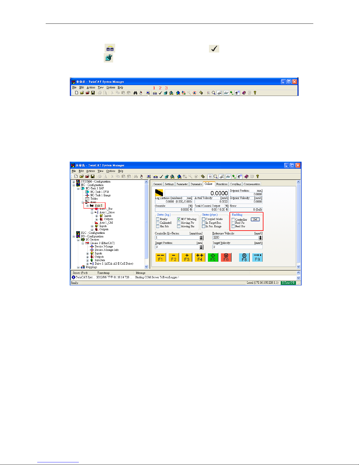
16. Switch TwinCAT to Run Mode.
Press to generate Mappings → press to check confiugration → and
press to activate configuration. TwinCAT will be switched to Run Mode
and then click OK in pop-up dialog.
Figure 18
17. Enable the axis (Servo On).
Under NC-Configuration of the left window, select Axis 1 → select Online
tab in the right window → click Set.
Figure 19
In pop-up dialog, click All to enable the motor.
Figure 20

ASDA A2-E Chapter 2 System Setup
2-10 Revision April, 2015
18. In Online tab, there are two different speed levels of jogging buttons for forward and
backward movement which can test the system. During the operation, please Be
Ensured that the movement would not damage your system and endanger the
personnel safety.
Figure 21
Chapter 2 System Setup ASDA A2-E
Revision April, 2015 2-11
2.3 Synchronization Modes Setting
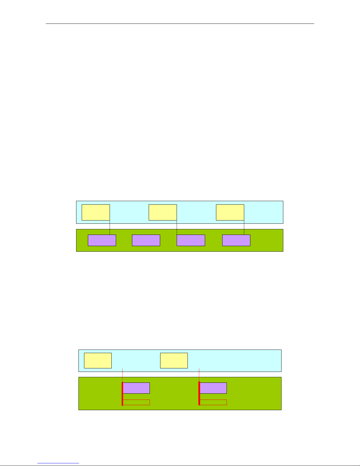
2.3.1 Two Synchronization Modes of Delta Servo
ASDA A2-E supports two synchronization modes, Free Run mode and DCSynchronous mode. Please note that the asynchronous Free Run mode is still under
the definition of “Synchronization Modes” within EtherCAT specification guide.
Free Run Mode (Asynchronous)
The master and slaves are running in an asynchronous manner. The master and
the slave both have their own clock to calculate the time. In other words, there is no
synchronous clock between the master and the slave. A command sent by the
master and a reply from the slave only consists with a sequential order instead of
strict clock timing. For example, a master sends a PDO at tick t1 and the slave will
receive it at tick t1 or tick t2 and vice versa.
EtherCAT
Data Frame
EtherCAT
Data Frame
EtherCAT
Data Frame
EtherCAT
Communication
Frame
ASDA-A2-E
Application
(Free Run)
Application
Task
Application
Task
Application
Task
Application
Task
No EtherCAT frame
Figure 22 Free Run Mode synchronization
DC-Synchronous Mode (SYNC0 synchronization)
There exists a clock tick for the master and all slaves operation. A data sent by the
master will be received by slave(s) at the same clock interval. The master will inform
all slaves about its clock and ask slaves to align according to the time. A strict clock
tick is always running within this system.
EtherCAT
Data Frame
EtherCAT
Data Frame
EtherCAT
Communication
Frame
ASDA-A2-E Application
(SYN0 Synchronization)
Application
Task
Application
Task
SYN0 Event SYN0 Event
Figure 23 DC-Synchronous mode synchronization
ASDA A2-E Chapter 2 System Setup
2-12 Revision April, 2015
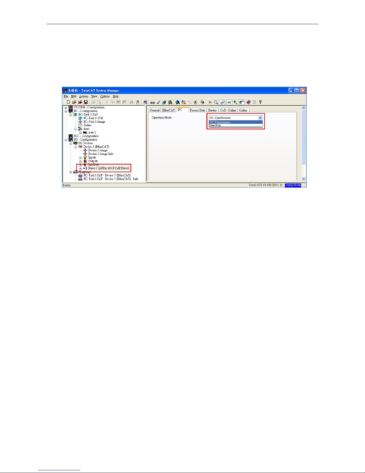
2.3.2 Select the Synchronization Mode
1. Select Drive (ASDA A2-E CoE Drive) in the left window.
2. The DC tab in the right window, users can select DC-Synchronous or Free Run as
the Operation Mode. This is for selecting synchronous or asynchronous mode.
Figure 24
2.3.3 Synchronous Clock Time Setting
1. Select NC-Task 1 SAF in the left window.
2. Click Task in the right window.
3. Cycle ticks are the data exchanging period under the Task tab.
Figure 25

Chapter 2 System Setup ASDA A2-E
Revision April, 2015 2-13
The unit of cycle for SYNC0 cycle time is 1ms.
SYNC0 cycle time supported
1ms (PDO cycle time = 1ms)
2ms (PDO cycle time = 2ms)
3ms (PDO cycle time = 3ms)
…
* SYNC0 cycle time is used to define PDO cycle time.

ASDA A2-E Chapter 2 System Setup
2-14 Revision April, 2015
2.4 PDO Mapping
The PDO mapping Objects are allocated from index 0x1600 to 0x1603 for RxPDOs and
0x1A00 to 0x1A03 for TxPDOs in Object Dictionary.
2.4.1 Default PDO Mappings
The following tables are the default PDO mappings of ASDA A2-E CoE Drive for cyclic
data exchange and are also defined in EtherCAT Slave Information file (XML file).
1st PDO Mapping
RxPDO
(0x1600)
Control Word
(0x6040)
Target Position
(0x607A)
Target Velocity
(0x60FF)
Target Torque
(0x6071)
Mode of Operation
(0x6060)
TxPDO
(0x1A00)
Status Word
(0x6041)
Actual Position
(0x6064)
Actual Velocity
(0x606C)
Actual Torque
(0x6077)
Mode of Operation Display
(0x6061)
2nd PDO Mapping (default PDO assignment)
RxPDO
(0x1601)
Control Word
(0x6040)
Target Position
(0x607A)
TxPDO
(0x1A01)
Status Word
(0x6041)
Actual Position
(0x6064)
3rd PDO Mapping
RxPDO
(0x1602)
Control Word
(0x6040)
Target Velocity
(0x60FF)
TxPDO
(0x1A02)
Status Word
(0x6041)
Actual Position
(0x6064)
Actual Velocity
(0x606C)

Chapter 2 System Setup ASDA A2-E
Revision April, 2015 2-15
4th PDO Mapping
RxPDO
(0x1603)
Control Word
(0x6040)
Target Torque
(0x6071)
TxPDO
(0x1A03)
Status Word
(0x6041)
Actual Position
(0x6064)
Actual Torque
(0x6077)
2.4.2 Re-define a PDO Mapping
Setup procedure
1. Set 【RxPDO Assignment:0x1C12:0/ TxPDO Assignment: 0x1C13:0】to 0x0 for
disabling the PDO assignment.
2. Set 【RxPDO mapping entry: ex. 0x1601:0/ TxPDO mapping entry: ex. 0x1A01:0】
to 0x0 for disabling the PDO mapping entry setting.
3. Set 【RxPDO mapping entry: ex. 0x1601:0 - 0x1601:7/ TxPDO mapping entry: ex.
0x1A01:0 - 0x1A01:7】.
4. Set 【RxPDO mapping entry: ex. 0x1601:0/ TxPDO mapping entry: ex. 0x1A01:0】
to the number of mapping entries in PDO mapping.
5. Set 【RxPDO Assignment:0x1C12:1/ TxPDO Assignment: 0x1C13:1】to PDO
assignment.
6. Set 【RxPDO Assignment:0x1C12:0/ TxPDO Assignment: 0x1C13:0】to 0x1 for
enabling the PDO assignment.

ASDA A2-E Chapter 2 System Setup
2-16 Revision April, 2015
2.4.3 Using TwinCAT
1. Press or Shift and F4 to set/reset TwinCAT to Config Mode (Click OK in pop-up
dialog).
2. Select Drive (ASDA A2-E CoE Drive) in the left window. In Process Data field, you
can change PDO Assignment for another PDO mapping.
3. Right click the PDO Content Window, and find the PDO mapping that you desire to
set, and then you can configure (Insert/Delete/Edit/Move Up/Move Down) the PDO
mapping content.
(8 PDOs is the maximum number of PDO which can be assigned in every PDO
mappings.)
Figure 27
Figure 28 ASD-A2-E CoE drive Object List

Chapter 2 System Setup ASDA A2-E
Revision April, 2015 2-17
4. After changing the PDO Assignment, press or F4 to reload I/O devices. (Click
No in pop-up dialog and stay in Config Mode.)

ASDA A2-E Chapter 2 System Setup
2-18 Revision April, 2015
(This page is intentionally left blank.)

Revision April, 2015 3-1
Chapter 3 EtherCAT
Communication States
ASDA A2-E supports four EtherCAT communication states which are shown as below:
Init (Initialization)
Pre-Operational
Safe-Operational
Operational
Init
Pre-operational
Safe-operational
Operational
(OI)
(IP) (PI)
(OP)
(PS)
(SP)
(SO)
(OS)
(SI)
Figure 29 The EtherCAT State machine
EtherCAT host controller can switch the states. Different state provides different
service.
State Description
Init
After power on, the system will be located in this state when hardware
is initialized without any error.
No communication packet is sent at this stage.
Pre-Operational
The mailbox can be accessed via SDO (Service Data Object).
The Emergency message will be sent to the host controller if any
alarm occurs.

Chapter 3 EtherCAT Communication States ASDA A2-E
3-2 Revision April, 2015
Safe-Operational
Except SDO, for accessing Mailbox, the PDO (Process Data Object)
can only be applied for Process Data Input (TxPDO) at this stage.
Operational
The full function of SDO and PDO (TxPDO and RxPDO) are available
now.
3.1 State Transition Operation
The EtherCAT host will send different state transition command for requesting different
service.
State Change Description
IP
Master will define the slave address and register SyncManager (0/1),
and it is possible to access mailbox.
Master will command the slave to switch to Safe-Operational state.
PS
SDO from the master will be employed for the settings of PDO
mapping.
Master will define FMMU and register SyncManager (2/3), and slaves
keep sending the PDO (TxPDO) packets to the master.
Master requests the Slave to switch to Operational state.
SO
Master starts to send PDO (RxPDO).
The distributed clock synchronization procedure takes place between
the master and slaves.
PI, SI, OI
All communication functions, including SDO and PDO cannot work.
Switch to Init State.
SP, OP
Disable PDO function.
Switch to Pre-Operational state
OS
Master stops sending Process Data Output (RxPDO).
Switch to Safe-Operational state

Revision April, 2015 4-1
Chapter 4 EtherCAT
Troubleshooting
Q: Why my TwinCAT cannot find EtherCAT Device from all installed NIC
(Network Interface Card) and only shows RT-Ethernet devices?
A:
1. Please refer to TwinCAT setup procedure and make sure NIC is installed
properly.
2. Check if the cable is correctly connected and L/A LED is lit.
Q: The dialog shows “Unknown device type found” while using TwinCAT Scan
boxes.
A: Copy XML description of the ASDA-A2-E to TwinCAT device description folder
(usually in C:\TwinCAT\Io\EtherCAT) and restart TwinCAT System.
Q: Why does EtherCAT state machine only show INIT in Current State and blank
in DLL status when TwinCAT is in Config Mode?
Figure 30
A:
1. Set parameter P1-01 to 0x0C (EtherCAT communication mode).
2. Check the wiring from the host to EtherCAT communication port CN6A for input
and CN6B for output on servo drive. If the Link LED lit, it indicates that the
physical connection is correct and the drive is connecting.

ASDA A2-E Chapter 4 EtherCAT Troubleshooting
4-2 Revision April, 2015
Q: TwinCAT shows “following error”.
Figure 31
A: Set “Following Error Calculation” to Extern:
1. Select Axis 1_Drive in the left window.
2. In Parameter tab, select Extern in Following Error Calculation.
3. Download and click OK in pop-up dialog.
Figure 32
Q: ASDA A2-E servo drive shows AL185
A: This alarm message occurs because of the disconnection of EtherCAT cable
between the host and the slave. Please check the wiring. After checking the
connection of the cable, it is necessary to re-servo on the drive or set OD 0x6040
to 0x86 for fault reset.
Chapter 4 EtherCAT Troubleshooting ASDA A2-E
Revision April, 2015 4-3
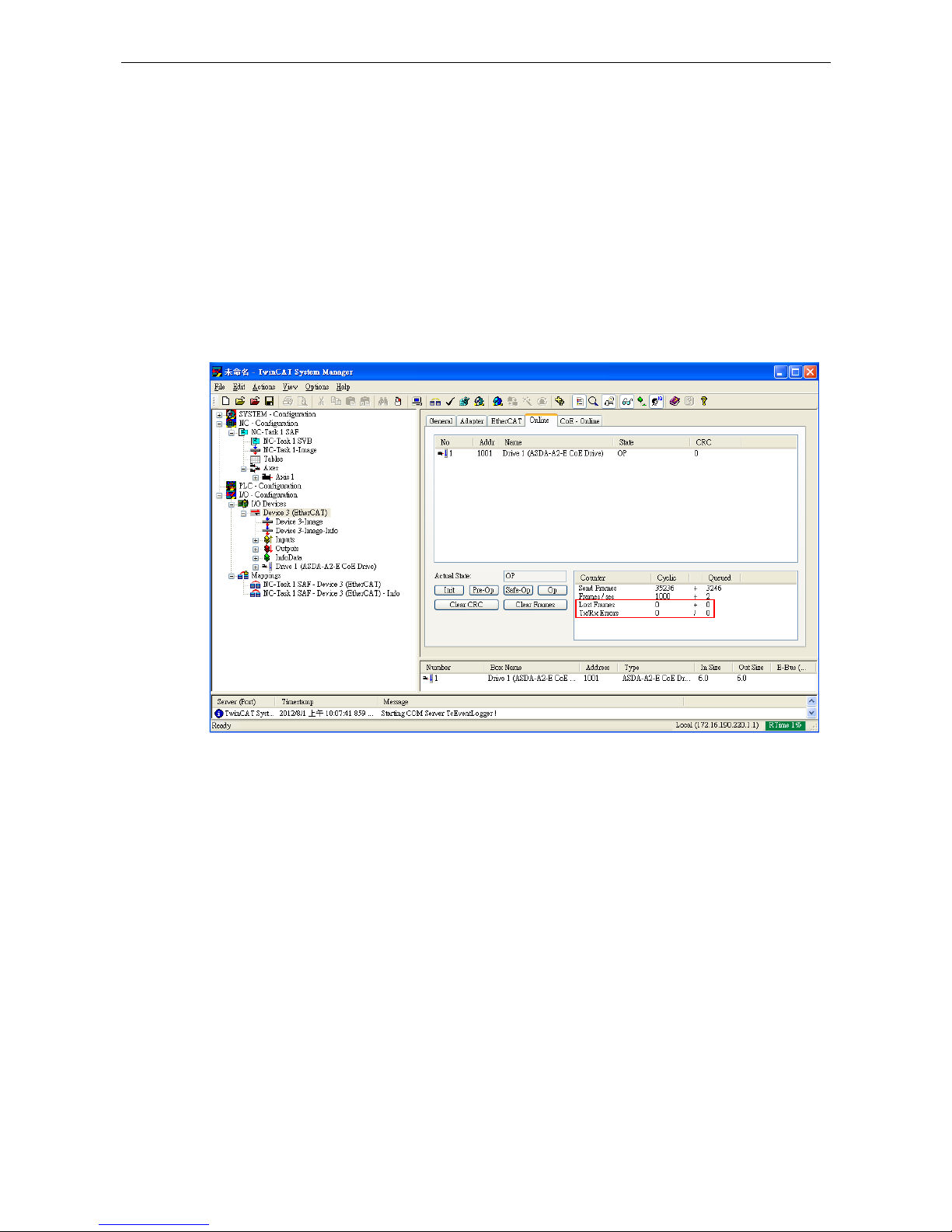
Q: ASDA A2-E servo drive shows AL180
A: Working under Operational state and losing three consecutive PDOs will lead to
this alarm.
1. A mechanism inside Delta Servo Drive can be used to monitor the error when
receiving PDO by setting P0-02 to 121. If the number keeps increasing, it can
be interpreted as the exaggerated jitter of PDO or server interference on the
communication cable.
2. Select drive and click Online. If the number in the columns of Lost Frames and
Rx Errors keeps increasing, it means the system have severe interference.
Figure 33
Q: ASDA A2-E servo drive servo drive shows AL3E1
A: Working under Operational state with CANopen CSP/CSV/CST mode and losing
two consecutive PDOs will lead to this alarm.
1. Check the reference clock whether with big time jitter
2. Fault reset with control word 0x6040.7 = 1
Q: ASDA A2-E servo drive shows AL3E3
A: Working under Operational state with CANopen CSP/CSV/CST mode and losing
two consecutive PDOs will lead to this alarm.
1. Make sure the host controller periodically and stably sends PDO.
2. Make sure grounding and wiring are both correct.

ASDA A2-E Chapter 4 EtherCAT Troubleshooting
4-4 Revision April, 2015
(This page is intentionally left blank.)

Revision April, 2015 5-1
Chapter 5 CANopen Operation
Mode
5.1 Profile Position Mode
5.1.1 Description
Servo drive (hereinafter referred to as “Drive”) receives position command from the
host (external) controller (hereinafter referred to as “Host”) and then controls servo
motor to reach the target position.
Pulse of User-defined Unit Definition:
Pulse of User Unit (PUU): No. of
= 1280000
5.1.2 Operation Procedures
1. Set 【Mode of operations:6060h】to profile position mode (0x01).
2. Set 【Target position:607Ah】to the target position (unit: PUU).
3. Set 【Profile velocity:6081h】to the profile velocity (unit: PUU per second).
4. Set 【Profile acceleration:6083h】to plan acceleration slope (millisecond from 0rpm
to 3000rpm).
5. Set 【Profile deceleration:6084h】to plan deceleration slope (millisecond from 0rpm
to 3000rpm).
6. Set 【Controlword:6040h】as (0x06 > 0x07 > 0x0F) to Servo On the drive and
enable the motor.
7. Read 【Statusword:6064h】to obtain feedback position of the motor.
8. Read 【Statusword:6041h】to obtain the drive status of the following error, setpoint acknowledge and target reached.

Chapter 5 CANopen Operation Mode ASDA A2-E
5-2 Revision April, 2015
5.1.3 Advanced Setting Procedures
1. Host could obtain more information about profile position mode.
Read 【Position demand value:6062h】to obtain the internal position command.
(unit: PUU)
Read 【Position actual value*:6063h】to obtain the actual position value. (unit:
increments)
2. Following error
Set 【Following error window:6065h】 to define the range of tolerated position
value, which also defines the range of the position demand value. (unit: PUU)
Read 【Following error actual value:60F4h】to obtain the actual value of the
following error. (unit: PUU)
following error
following error
window
position
no following error
reference position
following error
accepted following error tolerance
following error
window
Reference position
3. Position window
Set 【Position window:6067
h
】to define a symmetrical range of the accepted
positions which is relative to the target position. (unit: PUU)
Set 【Position window time:6068h】to plan activation time of target reached.
(unit: millisecond)

ASDA A2-E Chapter 5 CANopen Operation Mode
Revision April, 2015 5-3
position not reached
position window posi tion window
position
position reached
target position
position not reached
accepted position range
Position reached
5.1.4 Associated Object List
Index Name Type Attr.
6040h Controlword UNSIGNED16 RW
6041h Statusword UNSIGNED16 RO
6060h Modes of operation INTEGER8 RW
6061h Modes of operation display INTEGER8 RO
6062h Position demand value [PUU] INTEGER32 RO
6063h Position actual value [increment] INTEGER32 RO
6064h Position actual value INTEGER32 RO
6065h Following error window UNSIGNED32 RW
6067h Position window UNSIGNED32 RW
6068h Position window time UNSIGNED16 RW
607Ah Target position INTEGER32 RW
6081h Profile velocity UNSIGNED32 RW
6083h Profile acceleration UNSIGNED32 RW
6084h Profile deceleration UNSIGNED32 RW
6093h Position factor UNSIGNED32 RW
60F4h Following error actual value INTEGER32 RO
60FCh Position demand value INTEGER32 RO

Chapter 5 CANopen Operation Mode ASDA A2-E
5-4 Revision April, 2015
5.2 Interpolation Position Mode
5.2.1 Description
The Host sends PDO periodically. With each PDO, the Host sends the next reference
Xi, differece△Xi and controlword to the drive. While the next SYNC0 is receiving, the
drive interpolates from X
i-1
to X
i
.
Extrapolation, Jitter Compensation
- When PDO is delayed, the interpolator will predict the speed and position for
the next time according to the last acceleration.
- When PDO delays for 2*cycle, the Drive should stop and send out an error
message.
PDO Rx/Tx Mapping record
- The Drive receives PDOs from the Host
32 bit reference position [position increment]
16 bit symmetrical difference [increments]
△Xi = (X
i+1
– X
i-1
)/2 (It is also the same as velocity.)
16 bit controlword
The Drive receives PDOs from the Host (Every PDO contains 8 bytes field which is
shown as below.)
32 bit reference position 16 bit difference 16 bit controlword

ASDA A2-E Chapter 5 CANopen Operation Mode
Revision April, 2015 5-5
5.2.2 Operation Procedures
1. Set 【Mode of operations:6060h】to interpolation position mode(0x07).
2. Set 【Interpolation sub mode select:60C0h】to Interpolation mode.
If 60C0h is [0], the Host does not send [60C1h Sub-2]. It could save calculating
time of the host and the Drive could also work.
If 60C0h is [-1], the Host needs to send [60C1h Sub-2] and the Drive works more
precisely.
3. Set 【Interpolation time period:60C2h】to predict the cycle that SYNC0 receives
PDO.
60C2h Sub-1 for Interpolation time units. The range is from 1ms to 20ms.
- 60C2h Sub-2 for Interpolation time index. The value is always -3, meaning
the interpolation time unit is 10-3 second.
4. Drive PDO Rx:
60C1h Sub-1 for Pos Cmd (32-bit)
6040h Sub-0 for ControlWord.
5.2.3 Associated Object List
Index Name Type Attr.
6040h Controlword UNSIGNED16 RW
6041h Statusword UNSIGNED16 RO
6060h Modes of operation INTEGER8 RW
6061h Modes of operation display INTEGER8 RO
6093h Position factor UNSIGNED32 RW
60C0h Interpolation sub mode select INTEGER16 RW
60C1h Interpolation data record ARRAY RW
(Please refer to the following “Details of Objects” section for more detailed descriptions)

Chapter 5 CANopen Operation Mode ASDA A2-E
5-6 Revision April, 2015
5.3 Cyclic Synchronous Position Mode
5.3.1 Description
The Host plans the path in Cyclic Synchronous Position mode and sends PDO
periodically. With each PDO, the Host sends the target position and controlword to the
drive. Velocity offset and torque offset can be used as velocity and torque feedforwad.
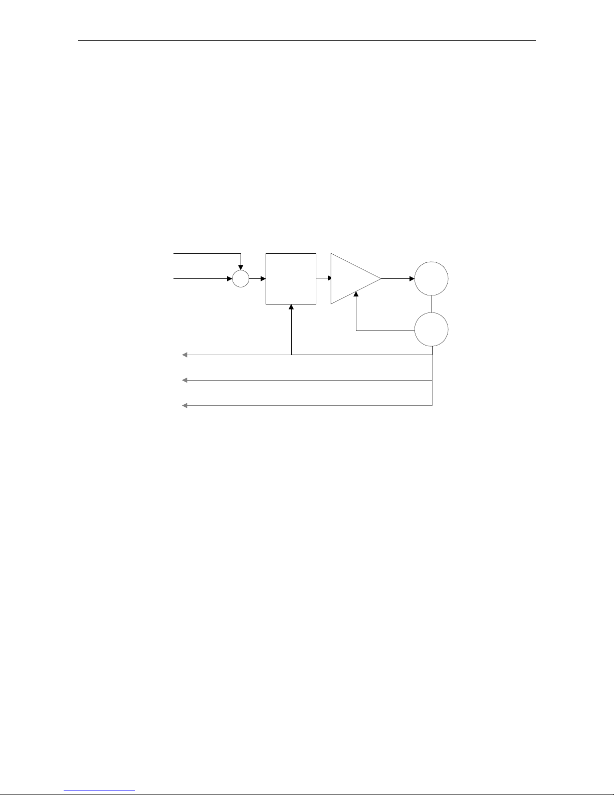
5.3.2 The Function of CSP Mode
Position
control
Velocity
control
Torque
control
M
S
Target
position
(607A
h
)
Position offset (60B0h)
Velocity offset (60B1h)
Torque offset (60B2h)
+
+
+
+
+
+
Position actual value
(6064
h
)
Velocity actual value
(606C
h
)
Torque actual value
(6077
h
)
5.3.3 Operation Procedures
1. Set 【Mode of operations:6060h】to cyclic synchronous position mode(0x08).
2. Set 【Interpolation time period:60C2h】 to predict the cycle that SYNC0 receives
PDO.
60C2h Sub-1 for Interpolation time units. The min is from 1ms to 20ms.
- 60C2h Sub-2 for Interpolation time index. The value is always -3, meaning
the interpolation time unit is 10-3 second.

ASDA A2-E Chapter 5 CANopen Operation Mode
Revision April, 2015 5-7
3. Drive PDO Rx:
607Ah for Target Pos Cmd (32-bit).
6040h Sub-0 for ControlWord.
5.3.4 Associated Object List
Index Name Type Attr.
6040h Controlword UNSIGNED16 RW
6041h Statusword UNSIGNED16 RO
6060h Modes of operation INTEGER8 RW
6061h Modes of operation display INTEGER8 RO
607A h Target position INTEGER32 RW
60B0 h Position offset INTEGER32 RW
6064 h Position actual value INTEGER32 RO
60B1
h
Velocity offset INTEGER32 RW
606C
h
Velocity actual value INTEGER32 RO
60B2
h
Torque offset INTEGER16 RW
6077
h
Torque actual value INTEGER16 RO
(Please refer to the following “Details of Objects” section for more detailed descriptions)

Chapter 5 CANopen Operation Mode ASDA A2-E
5-8 Revision April, 2015
5.4 Homing Mode
5.4.1 Description
This mode could help the drive to find the home position. Users can specify the speed,
acceleration and method of homing.
5.4.2 Operation Procedures
1. Set【Mode of operations:6060h】to the homing mode(0x06).
2. Set【Home offset:607Ch】.
3. Set【Homing method:6098h】. The method range is 1 to 35. (Refer to OD-6098h
definition which shows below.)
4. Set【Homing speeds:6099h Sub-1】in order to set speed search for switching. (unit:
rpm)
5. Set【Homing speeds:6099h Sub-2】in order to set speed during the search for zero.
(unit: rpm)
6. Set【Homing acceleration:609Ah】for homing acceleration. (unit: millisecond from
0rpm to 3000rpm)
7. Set【Controlword:6040h】to (0x06 0x07 0x0F) to Servo ON the drive and
enable the motor.
8. Set【Controlword:6040h】to (0x0F 0x1F) to find Home Switch and do homing.
9. Read【Statusword:6041h】to obtain the drive status.

ASDA A2-E Chapter 5 CANopen Operation Mode
Revision April, 2015 5-9
5.4.3 Associated Object List
Index Name Type Attr.
6040h Controlword UNSIGNED16 RW
6041h Statusword UNSIGNED16 RO
6060h Modes of operation INTEGER8 RW
6061h Modes of operation display INTEGER8 RO
607Ch Home offset INTEGER32 RW
6093h Position factor UNSIGNED32 RW
6098h Homing method INTEGER8 RW
6099h Homing speed ARRAY RW
609Ah Homing acceleration UNSIGNED32 RW
(Please refer to the following “Details of Objects” section for more detailed descriptions.)

Chapter 5 CANopen Operation Mode ASDA A2-E
5-10 Revision April, 2015
5.5 Profile Velocity Mode
5.5.1 Description
The drive could receive velocity command and plan acceleration and deceleration.
5.5.2 Operation Procedures
1. Set【Mode of operations:6060h】to profile velocity mode(0x03).
2. Set【Controlword:6040h】as (0x06 0x07 0x0F) to Servo ON the drive and
enable the motor.
(After Servo On, the internal velocity command will be reset and OD-60FFh will be
cleared.)
3. Set【Profile acceleration:6083h】to plan acceleration slope. (millisecond from 0rpm
to 3000rpm)
4. Set【Profile deceleration:6084h】to plan deceleration slope. (millisecond from 0rpm
to 3000rpm)
5. Set【Target velocity:60FFh】. The unit of the target velocity is 0.1rpm.
(If the drive is already servo-on, it will work immediately while receiving velocity
command. OD-60FFh will be cleared to 0 if OD-6060h [Mode] is changed, and
Servo-Off or Quick-Stop is activated.)
6. Read【Statusword:6041h】to obtain the drive status.

ASDA A2-E Chapter 5 CANopen Operation Mode
Revision April, 2015 5-11
5.5.3 Advanced Setting Procedures
1. Host could obtain the information of velocity mode.
Read【Velocity demand value:606Bh】to inquire the internal velocity command.
(unit: 0.1rpm)
Read【Velocity actual value:606Ch】to obtain the actual velocity value. (unit:
0.1rpm)
2. Host could set velocity monitor threshold.
Set【Velocity window:606Dh】to allocate velocity reached zone. (unit: 0.1rpm)
Set【Velocity widnow time:606Eh】in order to ensure the activation time is
before velocity reached. (unit: millisecond)
Set【Velocity threshold:606Fh】to allocate zero speed level. (unit: 0.1rpm)
5.5.4 Associated Object List
Index Name Type Attr.
6040h Controlword UNSIGNED16 RW
6041h Statusword UNSIGNED16 RO
6060h Modes of operation INTEGER8 RW
6061h Modes of operation display INTEGER8 RO
606Bh Velocity demand value INTEGER32 RO
606Ch Velocity actual value INTEGER32 RO
Index Name Type Attr.
606Dh Velocity window UNSIGNED16 RW
606Eh Velocity window time UNSIGNED16 RW
606Fh Velocity threshold UNSIGNED16 RW
60FFh Target velocity INTEGER32 RW
(Please refer to the following “Details of Objects” section for more detailed descriptions)

Chapter 5 CANopen Operation Mode ASDA A2-E
5-12 Revision April, 2015
5.6 Cyclic Synchronous Velocity Mode
5.6.1 Description
The Host plans the path in Cyclic Synchronous Velocity mode. In this mode, the Host
sends PDO periodically including target position and controlword to drive. In addition,
velocity offset and torque offset can be used as the velocity and torque feedforwad.
5.6.2 The Function of CSV Mode
Velocity
control
Torque
control
M
S
Target
velocity
(60FF
h
)
Velocity offset (60B1h)
Torque offset (60B2h)
+
+
+
+
Position actual value
(6064
h
)
Velocity actual value
(606C
h
)
Torque actual value
(6077
h
)
5.6.3 Operation Procedures
1. Set 【Mode of operations:6060h】to cyclic synchronous velocity mode(0x09).
2. Set 【Interpolation time period:60C2h】 to predict the cycle that SYNC0 receives
PDO.
60C2h Sub-1 for Interpolation time units. The min is from 1ms to 20ms.
- 60C2h Sub-2 for Interpolation time index. The value is always -3, meaning
the interpolation time unit is 10-3 second.

ASDA A2-E Chapter 5 CANopen Operation Mode
Revision April, 2015 5-13
3. Drive PDO Rx:
60F Fh for Target Velocity Cmd (32-bit)
6040h Sub-0 for ControlWord
5.6.4 Associated Object List
Index Name Type Attr.
6040h Controlword UNSIGNED16 RW
6041h Statusword UNSIGNED16 RO
6060h Modes of operation INTEGER8 RW
6061h Modes of operation display INTEGER8 RO
60FF h Target velocity INTEGER32 RW
60B1
h
Velocity offset INTEGER32 RW
606Ch Velocity actual value INTEGER32 RO
6064 h Position actual value INTEGER32 RO
60B2
h
Torque offset INTEGER16 RW
6077
h
Torque actual value INTEGER16 RO

Chapter 5 CANopen Operation Mode ASDA A2-E
5-14 Revision April, 2015
5.7 Profile Torque Mode
5.7.1 Description
The drive could receive torque command and plan profile torque slope.
5.7.2 Operation Procedures
1. Set 【Mode of operations:6060h】to profile torque mode(4).
2. Set 【Controlword:6040h】as (0x6 0x7 0x0F) to Servo ON the drive and
enable the motor.
(After Servo On the drive, the internal torque command will be reset and OD-6071h
will be cleared. It means the drive is servo-on and starts to receive the torque
command.)
3. Set 【Torque slope:6087h】to plan torque slope time. (unit: millisecond from 0 to
100% rated torque)
4. Set 【Target torque:6071h】to the target torque. The unit is given one rated torque
in a thousand. (OD-6071h will be cleared to 0 if OD-6060h [Mode] changed. ServoOff or Quick-Stop is activated.)
5.7.3 Advanced Setting Procedures
Host could obtain the information of torque mode.
Read 【Torque demand value:6074h】 to obtain the output value of the torque limit
function. (unit: one rated torque in a thousand)
Read 【Torque rated current:6075h】to obtain the rated current determined by the
motor and drive type. (unit: multiples of milliamp)
Read 【Torque actual value:6077h】to obtain the instantaneous torque in servo
motor. (unit: one rated torque in a thousand)

ASDA A2-E Chapter 5 CANopen Operation Mode
Revision April, 2015 5-15
Read 【Current actual value:6078h】to obtain the instantaneous current in servo
motor. (unit: one rated torque in a thousand)
5.7.4 Associated Object List
Index Name Type Attr.
6040h Controlword UNSIGNED16 RW
6041h Statusword UNSIGNED16 RO
6060h Modes of operation INTEGER8 RW
6061h Modes of operation display INTEGER8 RO
6071h Target torque INTEGER16 RW
6074h Torque demand value INTEGER16 RO
6075h Motor rated current UNSIGNED32 RO
6077h Torque actual value INTEGER16 RO
6078h Current actual value INTEGER16 RO
6087h Torque slope UNSIGNED32 RW
(Please refer to the following “Details of Objects” section for more detailed descriptions.)
Chapter 5 CANopen Operation Mode ASDA A2-E
5-16 Revision April, 2015
5.8 Cyclic Synchronous Torque Mode
5.8.1 Description
The Host plans the path in Cyclic Synchronous Torque mode. In this mode, the Host
sends PDO periodically including target position and controlword to drive. In addition,
velocity offset and torque offset can be used as the velocity and torque feedforwad.
5.8.2 The Function of CST Mode
Torque
control
M
S
Target
torque
(6071
h
)
Torque offset (60B2h)
+
+
Position actual value
(6064
h
)
Velocity actual value
(606C
h
)
Torque actual value
(6077
h
)
5.8.3 Operation Procedures
1. Set【Mode of operations:6060h】to cyclic synchronous torque mode (0x0A).
2. Set【Interpolation time period:60C2h】to predict the cycle that SYNC0 receives
PDO.
60C2
h
Sub-1 for Interpolation time units. The min is from 1ms to 20ms.
- 60C2h Sub-2 for Interpolation time index. The value is always -3, meaning
the interpolation time unit is 10
-3
second.
3. Drive PDO Rx:
6071
h
for Target Torque Cmd (16-bit)
6040h Sub-0 for ControlWord.

ASDA A2-E Chapter 5 CANopen Operation Mode
Revision April, 2015 5-17
5.8.4 Associated Object List
Index Name Type Attr.
6040h Controlword UNSIGNED16 RW
6041h Statusword UNSIGNED16 RO
6060h Modes of operation INTEGER8 RW
6061h Modes of operation display INTEGER8 RO
6071h Target torque INTEGER16 RW
60B2
h
Torque offset INTEGER16 RW
6077
h
Torque actual value INTEGER16 RO
606Ch Velocity actual value INTEGER32 RO
6064 h Position actual value INTEGER32 RO
(Please refer to the following “Details of Objects” section for more detailed descriptions)

Chapter 5 CANopen Operation Mode ASDA A2-E
5-18 Revision April, 2015
5.9 Limit Position Handling Procedure
5.9.1 Description
Drive will switch to Quick-Stop status while traveling to the position of positive or
negative limit sensors, and it can be handled by the following procedures.
5.9.2 Operation Procedures
1. The servo panel will show the alarm while sensors are close to the positive or
negative limit. The motor is controlled by a deceleration slope to stop and it is at
Quick-Stop status. The drive will keep in servo-on status but will not accept the
further motion command.
2. Set 【Controlword:6040h】to 0x8F for fault reset and clearing the alarm displayed
on the panel.
3. Set 【Controlword:6040h】to 0x1F/0x0F for Operation Enabled, and then the servo
can accept the motion command again.
4. For a motor at its limit position, there must be a command which can drive the motor
to the backward direction. Or the alarm will be triggered again while the motor starts
moving.

ASDA A2-E Chapter 5 CANopen Operation Mode
Revision April, 2015 5-19
5.10 Touch Probe Function
5.10.1 Description
Touch Probe function can be enabled by the DI on CN7 or the encoder; among that,
the feedback position can be latched as positive or negative edge with DI13 on CN7.
The time of latch position is shorter than 5 µs and it is used to execute high speed
performance in measuring or packaging applications.
5.10.2 Touch Probe Function
The current status of Touch Probe can be obtained by object 60B8h. The definition of
each bit is as the followings.
Bit Value Definition
0
0
Switch off touch probe 1
1
Enable touch probe 1
1
0
Trigger first event
1
Continuous
2
0
Trigger with touch probe 1 input
1
Trigger with zero impulse signal
3 0
Reserved
4
0
Switch off sampling at positive edge of touch
probe 1
1
Enable sampling at positive edge of touch probe 1
5
0
Switch off sampling at negative edge of touch
probe 1
1
Enable sampling at negative edge of touch probe
1
6、7
0
Reserved
8
0
Switch off touch probe 2
1
Enable touch probe 2
9
0
Trigger first event
1
Continuous
10
0
Trigger with touch probe 2 input

Chapter 5 CANopen Operation Mode ASDA A2-E
5-20 Revision April, 2015
1
Trigger with zero impulse signal
11
0
Reserved
12
0
Switch off sampling at positive edge of touch
probe 2
1
Enable sampling at positive edge of touch probe 2
13
0
Switch off sampling at negative edge of touch
probe 2
1
Enable sampling at negative edge of touch probe
2
14、15
Reserved
5.10.3 Touch Probe Status
The current status of Touch Probe can be obtained by object 60B9h. The definition of
each bit is as the followings.
Bit Value Definition
0
0 Touch probe 1 is switched off
1 Touch probe 1 is enabled
1
0 Touch probe 1 has no positive edge value stored
1 Touch probe 1 has positive edge value stored
2
0 Touch probe 1 has no negative edge value stored
1 Touch probe 1 has negative edge value stored
3 ~ 5 0 Reserved
6
0 Trigger with touch probe 1 input
1 Trigger with zero impulse signal
7
0,1
Toggle with every update of Touch probe 1 value
Stored
8
0 Touch probe 2 is switched off
1 Touch probe 2 is enabled
9
0 Touch probe 2 has no positive edge value stored
1 Touch probe 2 has positive edge value stored

ASDA A2-E Chapter 5 CANopen Operation Mode
Revision April, 2015 5-21
10
0 Touch probe 2 has no negative edge value stored
1 Touch probe 2 has negative edge value stored
11 ~ 13
0 Reserved
14
0 Trigger with touch probe 2 input
1 Trigger with zero impulse signal
15
0,1
Toggle with every update of Touch probe 2 value
Stored
5.10.4 Associated Object List
Index Name Type Attr.
60B8h
Touch probe function UNSIGNED16 RW
60B9h
Touch probe status UNSIGNED16 RO
60BAh
Touch probe pos1 pos value INTEGER32 RO
60BBh
Touch probe pos1 neg value INTEGER32 RO
60BCh
Touch probe pos2 pos value INTEGER32 RO
60BD
h
Touch probe pos2 neg value INTEGER32 RO
(Please refer to the following “Details of Objects” section for more detailed descriptions)

Chapter 5 CANopen Operation Mode ASDA A2-E
5-22 Revision April, 2015
(This page is intentionally left blank.)

Revision Aril, 2015 6-1
Chapter 6 Object Dictionary
Entries
6.1 Specifications for Objects
6.1.1 Object Type
Object Name Comments
VAR A single value such as an UNSIGNED8, Boolean, float, INTEGER16
etc.
ARRAY
A
multiple data field object where each data field is a sample variable
of the SAME basic data type e.g. array of UNSIGNED16 etc. Subindex 0 is UNSIGNED8 but is not part of the ARRAY data
RECORD A multiple data field object where the data fields may be any
combination of simple variables. Sub-index 0 is UNSIGNED8 but is
not part of the RECORD data
6.1.2 Data Type
Please refer to CANopen Standard 301.

Chapter 6 Object Dictionary Entries ASDA A2-E
6-2 Revision April, 2015
6.2 Overview of Object Group 1000
h
Index Object Type Name Data Type Access
1000h VAR device type UNSIGNED32 RO
1001h VAR error register UNSIGNED8 RO
1600h~03h RECORD Receive PDO mapping UNSIGNED32 RW
1A00h~03h RECORD Transmit PDO mapping UNSIGNED32 RW
※ Only 1001
h
could be mapped to PDO.

ASDA A2-E Chapter 6 Object Dictionary Entries
Revision April, 2015 6-3
6.3 Overview of Object Group 6000
h
Index
Object
Type
Name Data Type Access Mappable
603Fh VAR Error Code UNSIGNED16 RO Y
6040h VAR Controlword UNSIGNED16 RW Y
6041h VAR Statusword UNSIGNED16 RO Y
605Bh VAR Shutdown option code INTEGER16 RW N
605Eh VAR Fault reaction option code INTEGER16 RW N
6060h VAR Modes of operation INTEGER8 RW Y
6061h VAR Modes of operation display INTEGER8 RO Y
6062h VAR Position demand value [PUU] INTEGER32 RO Y
6063h VAR Position actual value
[increment]
INTEGER32 RO Y
6064h VAR Position actual value INTEGER32 RO Y
6065h VAR Following error window UNSIGNED32 RW Y
6067h VAR Position windows UNSIGNED32 RW Y
6068h VAR Position window time UNSIGNED16 RW Y
606Bh VAR Velocity demand value INTEGER32 RO Y
606Ch VAR Velocity actual value INTEGER32 RO Y
606Dh VAR Velocity window UNSIGNED16 RW Y
606Eh VAR Velocity window time UNSIGNED16 RW Y
606Fh VAR Velocity threshold UNSIGNED16 RW Y
6071h VAR Target torque INTEGER16 RW Y
6072h VAR Max torque UNSIGNED16 RW Y
6074h VAR Torque demand value INTEGER16 RO Y
6075h VAR Motor rated current UNSIGNED32 RO Y
6076h VAR Motor rated torque UNSIGNED32 RO Y
6077h VAR Torque actual value UNSIGNED16 RO Y
6078h VAR Current actual value INTEGER16 RO Y
607Ah VAR Target position INTEGER32 RW Y

Chapter 6 Object Dictionary Entries ASDA A2-E
6-4 Revision April, 2015
Index
Object
Type
Name Data Type Access Mappable
607Ch VAR Home Offset INTEGER32 RW Y
607Dh ARRAY Software position limit INTEGER32 RW Y
607Eh VAR Polarity UNSIGNED8 RW Y
607Fh VAR Max profile velocity UNSIGNED32 RW Y
6080h VAR Max motor speed UNSIGNED32 RW Y
6081h VAR Profile velocity UNSIGNED32 RW Y
6083h VAR Profile acceleration UNSIGNED32 RW Y
6084h VAR Profile deceleration UNSIGNED32 RW Y
6085h VAR Quick stop deceleration UNSIGNED32 RW Y
6086h VAR Motion profile type INTEGER16 RW Y
6087h VAR Torque slope UNSIGNED32 RW Y
6093h ARRAY Position factor UNSIGNED32 RW Y
6098h VAR Homing method INTEGER8 RW Y
6099h ARRAY Homing speeds UNSIGNED32 RW Y
609Ah VAR Homing acceleration UNSIGNED32 RW Y
60B0h VAR Position offset INTEGER32 RW Y
60B1h VAR Velocity offset INTEGER32 RW Y
60B2h VAR Torque offset INTEGER16 RW Y
60B8h VAR Touch probe function UNSIGNED16 RW Y
60B9h VAR Touch probe status UNSIGNED16 RO Y
60BAh VAR Touch probe pos1 pos value INTEGER32 RO Y
60BBh VAR Touch probe pos1 neg value INTEGER32 RO Y
60BCh VAR Touch probe pos2 pos value INTEGER32 RO Y
60BDh VAR Touch probe pos2 neg value INTEGER32 RO Y
60C0h VAR Interpolation sub mode select INTEGER16 RW Y
60C1h ARRAY Interpolation data record UNSIGNED16/32 RW Y
60C2h RECORD Interpolation time period SIGNED8 RW Y
60C5h VAR Max acceleration UNSIGNED32 RW Y
60C6h VAR Max deceleration UNSIGNED32 RW Y

ASDA A2-E Chapter 6 Object Dictionary Entries
Revision April, 2015 6-5
Index
Object
Type
Name Data Type Access Mappable
60F2h VAR Positioning option code UNSIGNED16 RW Y
60F4h VAR Following error actual value INTEGER32 RO Y
60FCh VAR Position demand value INTEGER32 RO Y
60FDh VAR Digital inputs UNSIGNED32 RO Y
60FFh VAR Target velocity INTEGER32 RW Y
6502h VAR Supported drive modes UNSIGNED32 RO Y
Delta parameter definition
2xxx VAR Parameter Mapping INTEGER16/32 RW Y

Chapter 6 Object Dictionary Entries ASDA A2-E
6-6 Revision April, 2015
6.4 Details of Objects
Object 1000h: Device Type
INDEX 1000h
Name device type
Object Code VAR
Data Type UNSIGNED32
Access RO
PDO Mapping No
Value Range UNSIGNED32
Default Value 04020192 h : A2 Series
Object 1001h: Error Register
INDEX 1001h
Name error register
Object Code VAR
Data Type UNSIGNED8
Access RO
PDO Mapping Yes
Value Range UNSIGNED8
Default Value 0
Object 1600
h
~ 1604h: Receive PDO Mapping Parameter
INDEX 1600h ~ 1603h
Name Receive PDO mapping
Object Code RECORD
Data Type PDO Mapping
Access RW
PDO Mapping No
Sub-Index 0
Description Number of mapped application objects in
PDO
Data Type UNSIGNED8
Access RW

ASDA A2-E Chapter 6 Object Dictionary Entries
Revision April, 2015 6-7
PDO Mapping No
Value Range 0: deactivated
1~8: activated
Default Value 0
Sub-Index 1~8
Description PDO mapping for the nth application object
to be mapped
Data Type UNSIGNED32
Access RW
PDO Mapping No
Value Range UNSIGNED32
Default Value 0
PDO Mapping
0
1
2
3
3
bbbb
cccc
aaaa
yy
zz
xx
08h
20h
10h
Object Dictionary
cccc zz
Application
Object 3
bbbb yy
Application
Object 2
aaaa xx
Application
Object 1
Application
Object 2
Application Object 1Application Object 3
Object 1A00h ~ 1A04h: Transmit PDO Mapping Parameter
Sub-Index 0
Description Number of mapped application objects in
PDO
Data Type UNSIGNED8
INDEX 1A00h ~ 1A03h
Name Transmit PDO mapping
Object Code RECORD
Data Type PDO Mapping
Access RW
PDO Mapping No

Chapter 6 Object Dictionary Entries ASDA A2-E
6-8 Revision April, 2015
Access RW
PDO Mapping No
Value Range 0: deactivated
1~8: activated
Default Value 0
Sub-Index 1~8
Description PDO mapping for the nth application object
to be mapped
Data Type UNSIGNED32
Access RW
PDO Mapping No
Value Range UNSIGNED32
Default Value 0
Object 1C12h : RxPDO assign
INDEX 1C12h
Name RxPDO assign
Object Code RECORD
Data Type PDO Mapping assign
Access RW
PDO Mapping No
Sub-Index 0
Description Number of assigned PDO mapping
Data Type UNSIGNED8
Access RW
PDO Mapping No
Value Range 0: deactivated
1: One PDO mapping be assigned to
SycManager2 for RxPDO
Default Value 1
Sub-Index 1
Description Index of assigned PDO mapping
Data Type UNSIGNED16
Access RW
PDO Mapping No

ASDA A2-E Chapter 6 Object Dictionary Entries
Revision April, 2015 6-9
Value Range 1600 h to 1603 h
Default Value 1601 h
Object 1C13h : TxPDO assign
INDEX 1C13h
Name TxPDO assign
Object Code RECORD
Data Type PDO Mapping assign
Access RW
PDO Mapping No
Sub-Index 0
Description Number of assigned PDO mapping
Data Type UNSIGNED8
Access RW
PDO Mapping No
Value Range 0: deactivated
1: One PDO mapping be assigned to
SycManager3 for TxPDO
Default Value 1
Sub-Index 1
Description Index of assigned PDO mapping
Data Type UNSIGNED16
Access RW
PDO Mapping No
Value Range 1A00 h to 1A03 h
Default Value 1A01 h
Object 603Fh: Error code (error code of CANopen defined)
INDEX 603Fh
Name Errorcode
Object Code VAR
Data Type UNSIGNED16
Access RO
PDO Mapping Yes
Value Range UNSIGNED16

Chapter 6 Object Dictionary Entries ASDA A2-E
6-10 Revision April, 2015
Default Value 0
Object 6040h: Controlword
INDEX 6040h
Name Controlword
Object Code VAR
Data Type UNSIGNED16
Access RW
PDO Mapping Yes
Value Range UNSIGNED16
Default Value P1-01 = 0x0C, Default is 0x0004
State Machine
ControlWord
(6040h)
StatusWord
(6041h)
State machine in system context
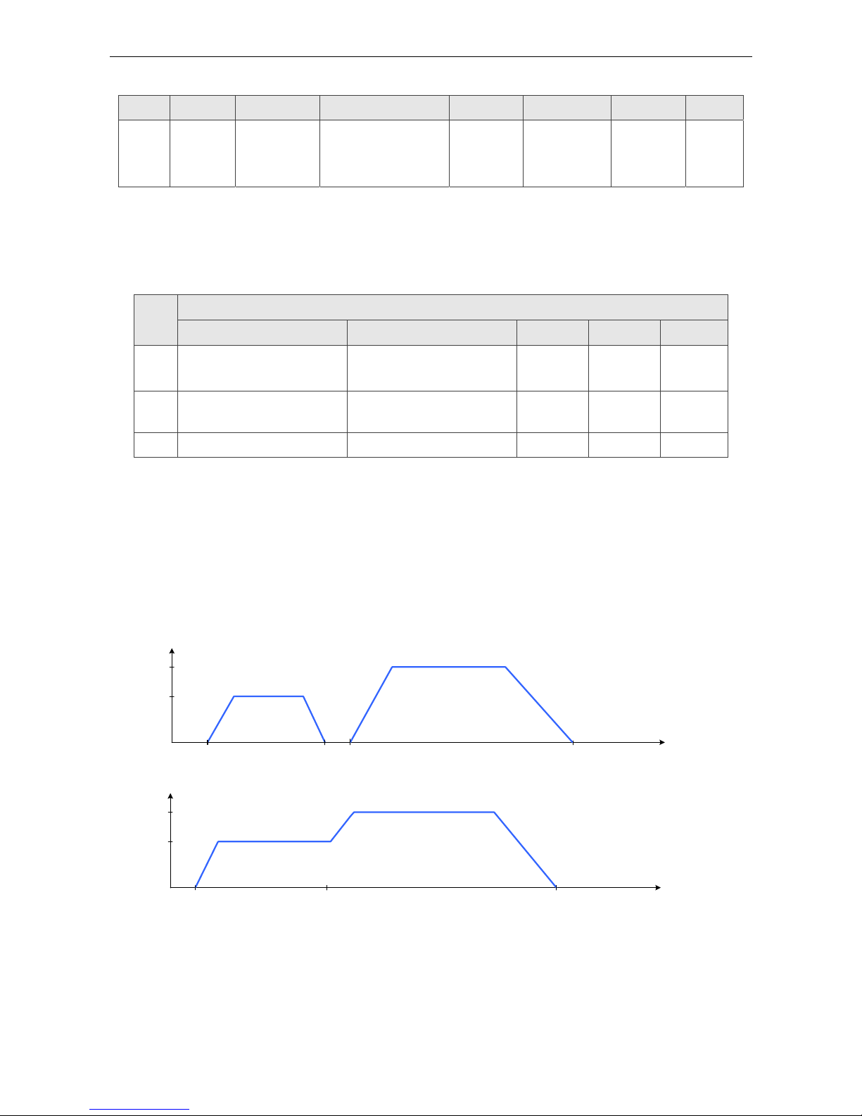
ASDA A2-E Chapter 6 Object Dictionary Entries
Revision April, 2015 6-11
Bit Definition
15~9 8 7 6~4 3 2 1 0
N/A Halt Fault reset
Operation mode
specific
Enable
operation
Quick
Stop
(B-contact)
Enable
voltage
Switch
on
Note:
The user needs to set 6040h to 0x0006->0x0007->0x000F for Servo On step by step.
Bit
Operation mode
PP HM IP PV PT
4 New set-point
(positive trigger)
Homing operation start
(positive trigger)
N/A N/A N/A
5 Change set
immediately
N/A N/A N/A N/A
6 Absolute(0) / relative(1) N/A N/A N/A N/A
Abbreviation:
PP
Profile Position Mode
HM
Homing Mode
IP
Interpolated Position Mode
PV
Profile Velocity Mode
PT
Profile Torque Mode
t1 t2t0 t3 time
v1
v2
Velocity
Single set-point
Velocity
v2
v1
t0
t1
t2 time
Change settings immediately

Chapter 6 Object Dictionary Entries ASDA A2-E
6-12 Revision April, 2015
Object 6041h: Statusword
INDEX 6041h
Name Statusword
Object Code VAR
Data Type UNSIGNED16
Access RO
PDO Mapping Yes
Value Range UNSIGNED16
Default Value 0
Data Description
15 14 13 12 11 10 9 8 7 6 5 4 3 2 1 0
MSB LSB
Bit Definition
0 Ready to switch on
1 Switch on
2 Operation enabled (status of servo on)
3 Fault (the drive will servo off)
4 Voltage enabled
5 Quick stop
6 Switch on disabled
7 Warning (the drive is still servo on)
8 N/A
9 Remote
10 Target reached
11 Internal limit active (Not supported)
PP HM IP PV PT
12
Set-point
acknowledge
Homing
attained
IP mode active Zero Speed N/A
13 Following error Homing error N/A N/A N/A
14 N/A N/A N/A N/A N/A
15 N/A N/A N/A N/A N/A
Note:
Set-point acknowledge: Trajectory generator has assumed the positioning values
Homing attained: Homing mode carried out successfu lly
IP mode active: interpolated position mode active – mode is running in IP mode

ASDA A2-E Chapter 6 Object Dictionary Entries
Revision April, 2015 6-13
Object 605Bh: Shutdown option code
INDEX 605Bh
Name Shutdown option code
Object Code VAR
Data Type INTEGER16
Access RW
PDO Mapping Yes
Value Range INTEGER16
Default Value 0
Comment 0:Disable drive function
-1:Dynamic break enable
Object 605Eh: Fault reaction option code
INDEX 605Eh
Name Fault reaction option code
Object Code VAR
Data Type INTEGER16
Access RW
PDO Mapping Yes
Value Range INTEGER16
Default Value 2
Comment 0:Disable drive, motor is free to rotate
1:slow down on slow down ramp
2:slow down on quick stop ramp
Object 6060h: Modes of operation
INDEX 6060h
Name Modes of operation
Object Code VAR
Data Type INTEGER8
Access RW
PDO Mapping Yes
Value Range INTEGER8
Default Value 0
Comment 0: Reserved
1: Profile position mode
3: Profile velocity mode

Chapter 6 Object Dictionary Entries ASDA A2-E
6-14 Revision April, 2015
4: Profile torque mode
6: Homing mode
7: Interpolated position mode
8: Cyclic synchronous position mode
9: Cyclic synchronous velocity mode
10: Cyclic synchronous torque mode
Object 6061h: Modes of operation display
INDEX 6061h
Name Modes of operation display
Object Code VAR
Data Type INTEGER8
Access RW
PDO Mapping Yes
Value Range INTEGER8
Default Value 0
Object 6062h: Position demand value
INDEX 6062h
Name Position demand value
Object Code VAR
Data Type INTEGER32
Access RO
PDO Mapping Yes
Value Range INTEGER32
Default Value 0
Comment Position command is calculated by
Interpolation theory
Unit: PUU
Object 6063h: Position demand value
INDEX 6063h
Name Position actual value*
Object Code VAR
Data Type INTEGER32
Access RO
PDO Mapping Yes
Value Range INTEGER32

ASDA A2-E Chapter 6 Object Dictionary Entries
Revision April, 2015 6-15
Default Value 0
Comment Unit: increments
Object 6064h: Position actual value
INDEX 6064h
Name Position actual value
Object Code VAR
Data Type INTEGER32
Access RO
PDO Mapping Yes
Value Range INTEGER32
Default Value 0
Comment Unit: PUU
Object 6065h: Following error window
INDEX 6065h
Name Following error window
Object Code VAR
Data Type UNSIGNED32
Access RW
PDO Mapping Yes
Value Range UNSIGNED32
Default Value 3840000
Comment Unit: PUU
Object 6067
h
: Position window
INDEX 6067h
Name Position window
Object Code VAR
Data Type UNSIGNED32
Access RW
PDO Mapping Yes
Value Range UNSIGNED32
Default Value 100
Comment Unit: PUU

Chapter 6 Object Dictionary Entries ASDA A2-E
6-16 Revision April, 2015
Object 6068h: Position window time
INDEX 6068h
Name Position window time
Object Code VAR
Data Type UNSIGNED16
Access RW
PDO Mapping Yes
Value Range UNSIGNED16
Default Value 0
Comment Unit: millisecond
Object 606Bh: Velocity demand value
INDEX 606Bh
Name Velocity demand value
Object Code VAR
Data Type INTEGER32
Access RO
PDO Mapping Yes
Value Range INTEGER32
Comment Unit: 0.1rpm
Object 606C
h
: Velocity actual value
INDEX 606Ch
Name Velocity actual value
Object Code VAR
Data Type INTEGER32
Access RO
PDO Mapping Yes
Value Range INTEGER32
Comment Unit: 0.1rpm

ASDA A2-E Chapter 6 Object Dictionary Entries
Revision April, 2015 6-17
Object 606Dh: Velocity window
INDEX 606Dh
Name Velocity window
Object Code VAR
Data Type INTEGER16
Access RO
PDO Mapping Yes
Value Range 0~3000
Default Value 100
Comment Unit: 0.1rpm
Object 606Eh: Velocity window time
INDEX 606Eh
Name Velocity window time
Object Code VAR
Data Type UNSIGNED16
Access RW
PDO Mapping Yes
Value Range UNSIGNED16
Default Value 0
Comment Unit: millisecond
Object 606F
h
: Velocity threshold
INDEX 606Fh
Name Velocity threshold
Object Code VAR
Data Type UNSIGNED16
Access RW
PDO Mapping Yes
Value Range 0~2000
Default Value 100
Comment Unit: 0.1rpm

Chapter 6 Object Dictionary Entries ASDA A2-E
6-18 Revision April, 2015
Object 6071h: Target torque
INDEX 6071h
Name Target torque
Object Code VAR
Data Type INTEGER16
Access RW
PDO Mapping Yes
Value Range -3000~3000
Default Value 0
Comment Unit: one rated torque in a thousand
Object 6072h: Max torque
INDEX 6072h
Name Max torque
Object Code VAR
Data Type UNSIGNED16
Access RW
PDO Mapping Yes
Value Range 0~3000
Default Value 3000
Comment Unit: one rated torque in a thousand
Object 6074h: Torque demand value
INDEX 6074h
Name Torque demand value
Object Code VAR
Data Type INTEGER16
Access RO
PDO Mapping Yes
Value Range INTEGER16
Comment Unit: one rated torque in a thousand

ASDA A2-E Chapter 6 Object Dictionary Entries
Revision April, 2015 6-19
Object 6075h: Motor rated current
INDEX 6075h
Name Motor rated current
Object Code VAR
Data Type UNSIGNED32
Access RO
PDO Mapping Yes
Value Range UNSIGNED32
Comment Unit: milliamp
Object 6076h: Motor rated torque
INDEX 6076h
Name Motor rated torque
Object Code VAR
Data Type UNSIGNED32
Access RO
PDO Mapping Yes
Value Range UNSIGNED32
Comment Unit: one rated torque in a thousand
Object 6077h: Torque actual value
INDEX 6077h
Name Torque actual value
Object Code VAR
Data Type INTEGER16
Access RO
PDO Mapping Yes
Value Range INTEGER16
Comment Unit: one rated torque in a thousand
Object 6078h: Current actual value
INDEX 6078h
Name Current actual value
Object Code VAR
Data Type INTEGER16
Access RO

Chapter 6 Object Dictionary Entries ASDA A2-E
6-20 Revision April, 2015
PDO Mapping Yes
Value Range INTEGER16
Comment Unit: one rated current in a thousand
Object 607Ah: Target position
INDEX 607Ah
Name Target position
Object Code VAR
Data Type INTEGER32
Access RW
PDO Mapping Yes
Value Range INTEGER32
Default Value 0
Comment For Profile position mode 6060h=1
Unit: PUU
Object 607Ch: Home offset
INDEX 607Ch
Name Home offset
Object Code VAR
Data Type INTEGER32
Access RW
PDO Mapping Yes
Value Range INTEGER32
Default Value 0
Comment Unit : PUU
home offset
Home
Position
Zero
Position
Home offset

ASDA A2-E Chapter 6 Object Dictionary Entries
Revision April, 2015 6-21
Object 607Dh: Software position limit
INDEX 607Dh
Name Software position limit
Object Code ARRAY
Data Type INTEGER32
Access RW
PDO Mapping Yes
Sub-Index 0
Description Number of entries
Data Type UNSIGNED8
Access RO
PDO Mapping Yes
Value Range 2
Default Value 2
Sub-Index 1
Description Min position limit
Data Type INTEGER32
Access RW
PDO Mapping Yes
Value Range -2147483648 ~ +2147483647
Default Value -2147483648
Comment Unit: PUU
Sub-Index 2
Description Max position limit
Data Type INTEGER32
Access RW
PDO Mapping Yes
Value Range -2147483648 ~ +2147483647
Default Value +2147483647
Comment Unit: PUU

Chapter 6 Object Dictionary Entries ASDA A2-E
6-22 Revision April, 2015
Object 607Fh: Max profile velocity
INDEX 607Fh
Name Max profile velocity
Object Code VAR
Data Type UNSIGNED32
Access RW
PDO Mapping Yes
Value Range UNSIGNED32
Default Value P1-55(rpm) * 10
Comment Unit:0.1rpm
Object 6080h: Max motor speed
INDEX 6080h
Name Max motor speed
Object Code VAR
Data Type UNSIGNED32
Access RW
PDO Mapping Yes
Value Range UNSIGNED32
Default Value P1-55(rpm)
Comment Unit: rpm
Object 6081
h
: Profile velocity
INDEX 6081h
Name Profile Velocity
Object Code VAR
Data Type UNSIGNED32
Access RW
PDO Mapping Yes
Value Range UNSIGNED32
Default Value 10000
Comment For Profile position mode 6060h=1
Unit: PUU per second

ASDA A2-E Chapter 6 Object Dictionary Entries
Revision April, 2015 6-23
Object 6083h: Profile acceleration
INDEX 6083h
Name Profile acceleration
Object Code VAR
Data Type UNSIGNED32
Access RW
PDO Mapping Yes
Value Range 1~UNSIGNED32
Default Value 200
Comment For Profile position mode 6060h=1 & Profile
velocity mode 6060h = 3
Unit: millisecond (time from 0rpm to
3000rpm)
Object 6084h: Profile deceleration
INDEX 6084h
Name Profile deceleration
Object Code VAR
Data Type UNSIGNED32
Access RW
PDO Mapping Yes
Value Range 1~UNSIGNED32
Default Value 200
Comment For Profile position mode 6060h=1 & Profile
velocity mode 6060h = 3
Unit: millisecond (time from 0rpm to
3000rpm)
Object 6085h: Quick stop deceleration
INDEX 6085h
Name Quick stop acceleration
Object Code VAR
Data Type UNSIGNED32
Access RW
PDO Mapping Yes
Value Range UNSIGNED32
Default Value 0
Comment Unit: millisecond (time from 0rpm to
3000rpm)

Chapter 6 Object Dictionary Entries ASDA A2-E
6-24 Revision April, 2015
Object 6086h: Motion profile type
INDEX 6086h
Name Motion profile type
Object Code VAR
Data Type INTEGER16
Access RW
PDO Mapping Yes
Value Range INTEGER16
Default Value 0
Object 6087h: Torque slope
INDEX 6087h
Name Torque slope
Object Code VAR
Data Type UNSIGNED32
Access RW
PDO Mapping Yes
Value Range UNSIGNED32
Default Value 0
Comment
Unit: millisecond (time from 0 to 100%
rated torque)
Object 6093h: Position factor
INDEX 6093h
Name Position factor
Object Code ARRAY
Data Type UNSIGNED32
Access RW
PDO Mapping Yes
Comment Position factor =
Numerator / Feed_constant
Sub-Index 0
Description Number of entries
Data Type UNSIGNED8
Access RO
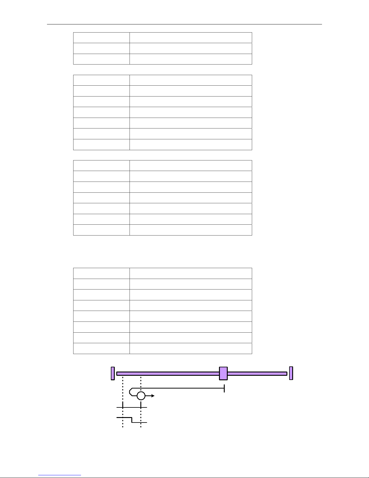
ASDA A2-E Chapter 6 Object Dictionary Entries
Revision April, 2015 6-25
PDO Mapping No
Value Range 2
Default Value 2
Sub-Index 1
Description Numerator
Data Type UNSIGNED32
Access RW
PDO Mapping Yes
Default Value 1
Comment Same as P1-44
Sub-Index 2
Description Feed_constant
Data Type UNSIGNED32
Access RW
PDO Mapping Yes
Default Value 1
Comment Same as P1-45
Object 6098h: Homing method
INDEX 6098h
Name Homing method
Object Code VAR
Data Type INTEGER8
Access RW
PDO Mapping Yes
Value Range 0~35
Default Value 0
1
Index Pulse
Negtive Limit Switch
Method1:Homing on negative limit switch and index pulse
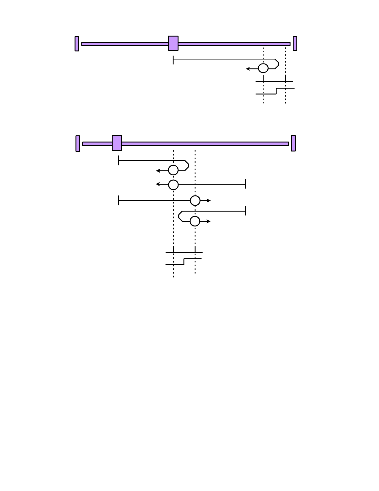
Chapter 6 Object Dictionary Entries ASDA A2-E
6-26 Revision April, 2015
Index Pulse
Positive Limit Switch
2
Method2:Homing on positive limit switch and index pulse
Home Switch
Index Pulse
3
4
3
4
Method 3 and 4:Homing on positive home switch and index pulse
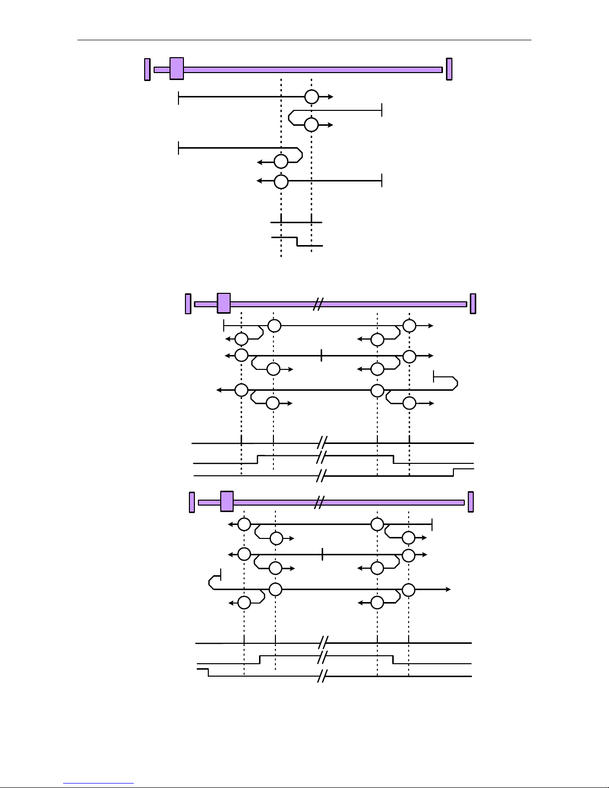
ASDA A2-E Chapter 6 Object Dictionary Entries
Revision April, 2015 6-27
Home Switch
Index Pulse
6
5
6
5
Method 5 and 6:Homing on negative home switch and index pulse
Home Switch
Index Pulse
7
7
8 10
9
10
8 9
8
7
10
9
Positive Limit Switch
Home Switch
Index Pulse
13
14
14 12
11
11
13 12
14
13
12
11
Negative Limit Switch
Method 7 to 14:Homing on home switch and index pulse
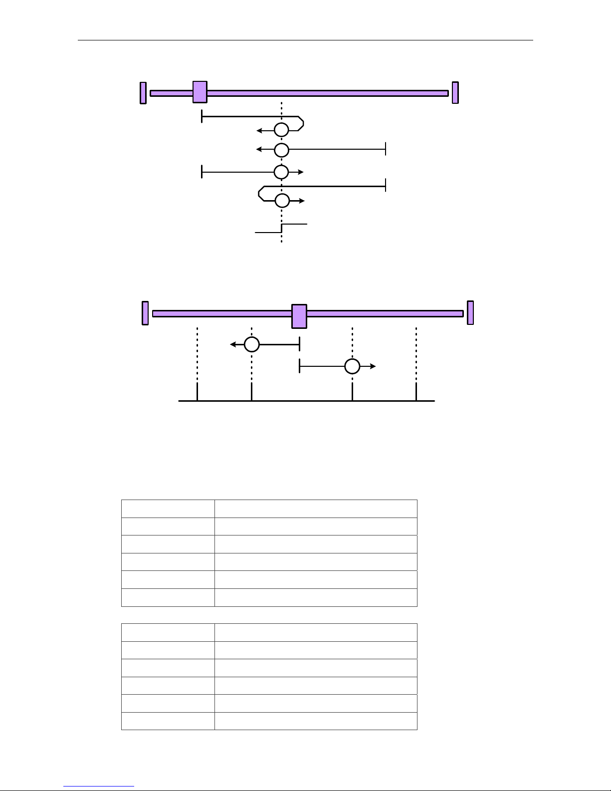
Chapter 6 Object Dictionary Entries ASDA A2-E
6-28 Revision April, 2015
Method 15 and 16:Reserved (no picture)
Home Switch
19
20
19
20
Method 17 to 30:Homing without an index pulse
Method 31 and 32:Reserved (no picture)
33
34
Index Pulse
Method 33 to 34:Homing on index pulse
Method 35:Homing on current position (no picture)
Object 6099h: Homing speed
INDEX 6099h
Name Homing speed
Object Code ARRAY
Data Type UNSIGNED32
Access RW
PDO Mapping Yes
Sub-Index 0
Description Number of entries
Data Type UNSIGNED8
Access RO
PDO Mapping Yes
Value Range 2

ASDA A2-E Chapter 6 Object Dictionary Entries
Revision April, 2015 6-29
Default Value 2
Sub-Index 1
Description Speed during search for switch
Data Type UNSIGNED32
Access RW
PDO Mapping Yes
Value Range 1~2000rpm
Default Value 100
Comment Unit:0.1rpm
Sub-Index 2
Description Speed during search for zero
Data Type UNSIGNED32
Access RW
PDO Mapping Yes
Value Range 1~500rpm
Default Value 20
Comment Unit:0.1rpm
Object 609Ah: Homing acceleration
INDEX 609Ah
Name Homing acceleration
Object Code VAR
Data Type UNSIGNED32
Access RW
PDO Mapping Yes
Value Range UNSIGNED32
Default Value 100
Comment Unit: millisecond (time of acc from 0rpm to
3000rpm)
 Loading...