

Page 1

SHEET 1 TO 2
Page 2

DELTA DOC CENTER
SHEET 2 TO 3
1. IMPORTANT SAFETY INSTRUCTIONS
1-1 UL safety instructions
SAVE THESE INSTRUCTIONS - This manual contains important instructions for
our UPS that should be followed during installation a nd maintenance of the UPS and
batteries.
-
To reduce the risk of electric shock, install this UPS in a temperature and humidity
controlled indoor area free of conductive contaminants. Ambient temperature must
not exceed 40°C (104°F).
-
The AC output of the UPS need a disconnect switch such as a breaker which has to
be provided by others.
-
The over-current protection for the output AC circuit has to be provided by others.
All of our UPS has an e lectronic protection of AC output short circuit.
[1KVA MODEL]Federal Communications Commission Interference State ment
This equipment has been tested and f ound to comply with the limits for a Class B digital
device, pursuant to Part 15 of the FCC Rules. These limits are designed to provide
reasonable protection against harmful interference in a residential installation. This
equip ment gene r ate s, us es a nd ca n ra dia te ra di o fre qu enc y e nergy a nd, if no t i nstal le d an d
used in accordance with the instructions, may cause harmful interference to radio
communications. However, there is no guarantee that interference will not occur in a
particular installation. If this equipment does cause harmful interference to radio or
television reception, which can be determined by turning the equipment off and on, the
user is encouraged to try to correct the interference by one of the following measures:
-
Reorient or relocate the receiving antenna
-
Increase the separation between the equipment and receiver.
-
Connect the equipment into an outlet on a circuit different from that to which the
receiver is connected.
-
Consult the dealer or an experienced radio/TV technician for help.
FCC Caution: To assure continued compliance, (example-use only shielded interface
cables when connecting to computer or peripheral devices ). Any changes or modifications
not expressly approved by the party responsible for compliance could void the user’s
authority to operate this equipment.
This device complies with Part 15 of the FCC Rules. Operation is subject to the following
two conditions: (1)this device may not cause harmful interference, and (2) this device
must accept any interference received, including interference that may cause undesired
operation.
DELTA PRODUCTS CORPORATIION CALIFORNIA (DPC)
4405 CUSHING PARKWAY
FREMONT, CA94538, U.S.A.
TEL: 1-510-668-5100
1
Page 3

DELTA DOC CENTER
SHEET 3 TO 4
Other safety notes:
-
Examin e the pac king c ontaine r for d amage. Notify t he carr ier imm edia tely if da mage
is present.
-
Do not disassemble the UPS.
-
Plug the UPS into a grounded 3-wire AC receptacle only.
-
Do not use extension cords.
-
Do not operate in area near water or excessive humidity.
-
Keep liquid and foreign objects from getting inside the UPS.
-
Install UPS in a well-ventilated area. Do not block air vents in front of UPS or air
exhausts in the back.
-
Do not operate close to gas or electric half bridge rectified load, into the UPS
receptacles.
-
Do not plug appliances, such as half bridge rectified load, into the UPS receptacles.
-
Do not operate if the uni t i s leaking liquid or if a white powdery residue is present.
-
Batteries may contain metals and other chemical hazardous waste. For proper disposal,
consult your local state and federal EPA and other environmental laws and
regulations.
-
Use only the power supply cord provided with this unit. The power cord for UPS is
wired in accordance with National Elec trical Code (NEC) specifications. Be sure that
the wall outlet is wired to these specif ic ations into the wall outlet.
-
The UPS contains its own e nergy source (battery). The output recept acles may be live
even when the UPS is not connecte d to an AC supply.
-
Once you have connected the batte ry connectors, do not attempt to lift the cabinets.
-
Do not connect or disconnect the battery cabinets while the UPS is operating from
battery.
[2,3KVA MODELS] Federal Communications Commiss ion Interf ere nce Statement
This equipment has been tested and found to comply with the limits for a Class A digital
device, pursuant to Part 15 of the FCC Rules. These limits are designed to provide
reasonable protection against harmful interference when the equipment is operated in a
commercial environment. This equipment gene rates, uses and can radiate radio frequency
energy and, if not installed and used in accordance with the instructions manual, may
cause harmful interference to radio communications. Operation of this equipment in a
residential area is likely to cause harmful interference in which case the user will be
required to correct the interference at his own expense.
FCC Caution: To assure continued compliance, (example-use only shielded interface
cables when connecting to computer or peripheral devices ). Any changes or modifications
not expressly approved by the party responsible for compliance could void the user’s
authority to operate this equipment.
2
Page 4

DELTA DOC CENTER
SHEET 4 TO 5
1-2 TUV safety instructions
Please observe the following precautions to ensure personnel safety and reliable
equipment operation:
-
The sound pressure level at the operators position according to IEC 704-1:1982 is
equal or less than 70dB(A).
-
Der arbeitsplatzbezogene Schalldruckpegel dieses Gerätes nach DIN 45635 beträgt
70dB (A) oder weniger.
For installation:
-
The unit should be installed from service personnel.
-
Dieses Gerät ist durch Elektrofachkräfte zu installieren.
-
To prevent an overbalance of this equipment, the stabilizer must be mounted at the
bottom of the enclosure.
-
Upon installation, it should be e nsured that the sum of the leakage current of the UPS
and the connected consumer does not exceed 3.5mA.
-
Bei der Installation dieses Gerätes ist da ra uf zu acht en, daβ die Ableitströme der USV
und der angeschlossenen Verbraucher den Maximalwert von 3.5 mA nicht
ü
berschreiten.
-
The socket-outlet shall be near the equipme nt and easily access ibl e.
-
Die Gerätesteckdose muβ nahe dem Gerät angebracht und leicht zugänglich sein.
Other safety instructions:
-
The UPS contains voltages which are potentially hazardous. All repairs should be
performed by qualified service personnel. The UPS has its own internal energy source
(Battery). The output receptacles may be alive even when the UPS is not connected to
the mains.
-
Die USV enthält Spannungen die möglicherweise gefährlich sind. Alle Reparaturen
sollten nur von ausgebildeten Monteuren durchgeführt werden. Die USV hat eine
interne Stromversorgung (Batterien). Die Ausgangsanschlüsse können daher unter
Strom stehen auch wenn die USV nicht an das Versorgungsnetz angeschlossen ist.
-
When replacing batteries, always use the same type and quantity as the previous one.
Batteries of GP1270-F2(CSB), NP7-12(YUASA) , 1234W(CSB).
-
Falls Sie die Batterien austauschen, verwenden Sie bitte ausschlieβlich die gleiche
Anzahl und die folgenden Batterietypen: GP1270-F2(CSB), NP7-12(YUASA),
1234W(CSB).
-
Do not dispose the battery or batteries in fire as this may explode.
-
Werfen Sie niem als die Batterien in das Feuer, die Batterien könnten explodieren.
-
Do not open or mutilate the battery or batteries as released electrolyte is toxic and
harmful to skin and eyes.
Ö
-
ffnen oder beschädigen Sie nicht die Batte rien, ausflieβendes Elektrolyt ist schädlich
für Haut und Augen.
3
Page 5

DELTA DOC CENTER
SHEET 5 TO 6
-
A battery can present a risk of electric shock and high short circuit current. The
following precaution should be observed when working on batteries.
•
•
-
Eine Batterie kann eine Gefahr eines elektrischen Schlages und sehr groβer Kurzsc hlu
ströme beinhalten. Folgende Vorkehrungen s ollten getroffen werden, wenn Sie mit der
Batterie arbeiten.
-
The equipment is to be operated by fully trained personnels.
-
Diese Gerät ist nur durch unterwiesenes Personal zu bediene n.
-
EC conformity declaration
-
These devices comply with the regulations of the following guide-lines:
-
73/23/EEC guide-line of the Council for approximation of the legal regulations of the
EC countries concerning the electrical apparatus within certain voltage tolerances,
modified by the guide-line RL 93/68/EEC of the Council.
Remove watches, rings or other metal objects .
Use tools with insulated handles.
∗
Entfernen Sie Uhren, Ri nge und andere metallische Obj e kte.
∗
Verwenden Sie Werkzeug mit isollierten Griffen.
β
-
89/336/EEC guide-line of the Council for approximation of the legal regulations of the
EC countries concerning the electromagnetic compatibility, modified by the
guide-lines RL 91/236/EEC,.... ..... and 93/68/E EC of the Council.
-
The compliance with the following standards proves the conformity:
-
EN 50091-1-1
-
EN 55022/EN 55011, class B.
4
Page 6
DELTA DOC CENTER
SHEET 6 TO 7
2 INTRODUCTION
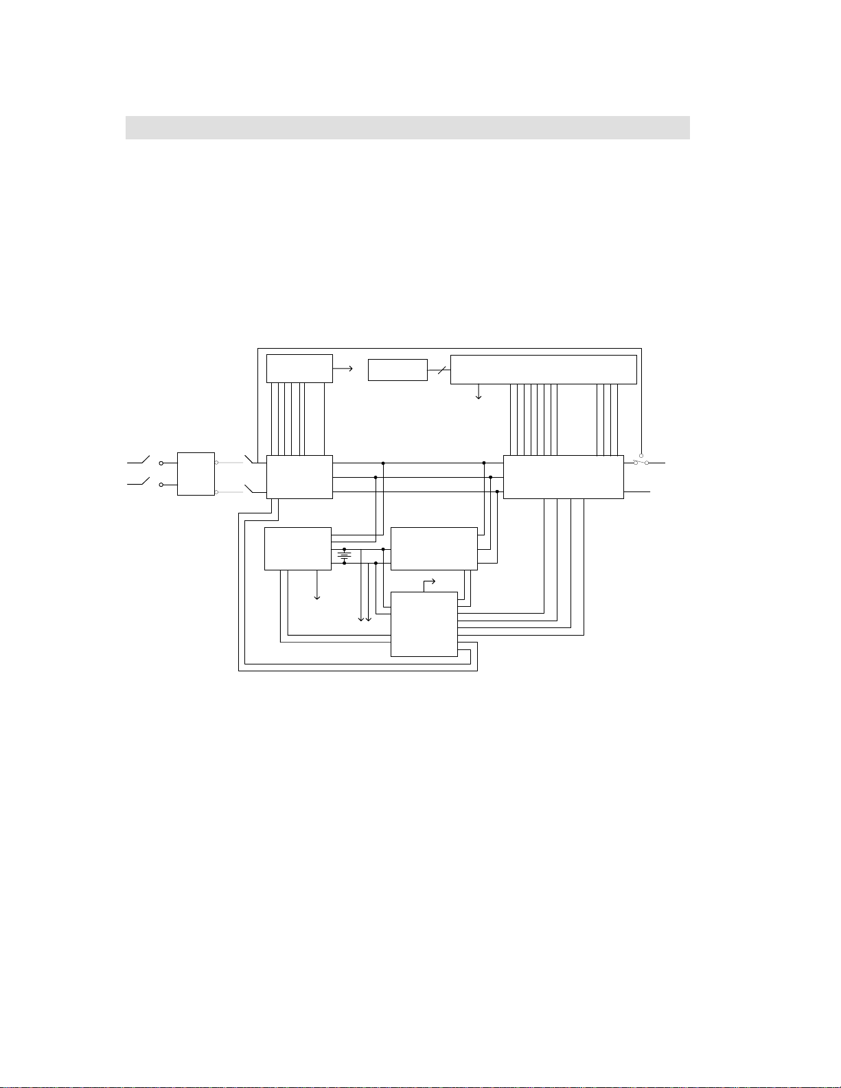
2-1 Theory of operation
The main topology of the UPS consists of bypass path, AC-DC converter, DC-AC
inverter, battery charger, DC-DC converter, control circuit and detection circuit.
Moreover, the intelligent power managem ent software is also optional. The function
and efficiency are superior to the traditional UPS.
Description of block diagram
BYPASS
PFC Control
Circuit
LED Board
To Control Board
To Auxiliary Power
Control Board
Breaker
AC
I/P
EMI
Filter
Relay
AC-DC Double
Booster
Battery Bank
Charger DC-DC Converter
To Control Board
To Control Board
To External Battery Bank
Auxiliary
Power
Half-bridge DC-AC Inverter
BYPASS
RELAY
O/P
AC
Fig. 2.1 is the ha rdware block diagram of the UPS.
The UPS operation is desc ribed as below:
When the utility power is applied into the UPS, it was di vided into two ways a fter going
through the breaker and EMI filter. One way is connected to AC-DC converter which
converts the utility AC power into a DC voltage which is called DC-BUS voltage then
divide into two path. One path goes to charger which converts the DC-BUS voltage into a
proper DC voltage to c harge the UPS battery. The other path goes into DC-AC half bridge
inverter. The other way works as a bypass path. The bypass relay near the output will
choose either the bypass path or inverter output. In general, the UPS will internally do the
self-diagnosis. If there is no problem, the bypass relay will choose the inverter output.
This is so called “
ON-LINE mode”.
5
Page 7

DELTA DOC CENTER
In case the utility power fail, the AC-DC converter and charger will be off duty. The
SHEET 7 TO 8
DC-DC converter works and converts the battery voltage into DC-BUS voltage. The
DC-AC inverter converts the DC-BUS voltage into AC voltage. This is so called
“
ON-BATTERY mode”.
The auxiliary power circuit suppl ies the designated power to al l the control circuits.
Because the DC-AC inverter is always working, the DC-DC convert er can work rapidly
and replace the AC-DC converter while the utility power fails. Furthermore, the bypass
relay continuously keeps in the posi tion of inverter output to supply the regulated power
for the load. There i s no power failure to loading e quipment.
2-2 Feature
The UPS, available in 700VA, 1KVA, 2KVA and 3KVA, is an advanced on-line UPS
providing reliable and consistent sine-wave quality power to vital equipment. It supports
personal computers, networks, servers, telecommunication equipment and a variety of
other facilities. With its out standing protection features, the unit keeps your applications
safe and running smoothl y a t all times.
High power density
Other than traditional UPS adopting 0.7 output power factor, the UPS uses the latest
technology and highest quality components giving output power factor up to 0.8.
Compared to other UPS (1000VA/700W), these UPS series boosts a 12% more output
power. This UPS with its compact size, generates higher power density thus giving
convenience to the users. Moreover, through the use of advanced technology, the UPS
efficiency increases to more than 87%. Compared with other traditional UPS wit h only 80
to 85% efficiency, this UPS produces greater electric power efficiency at less electric
costs.
PFC (Power Factor Correction)
With this function, the investment in the capacity of circuit breakers can be reduced,
specially it will be highly regarded as an important feature in critical load applications.
Complete Protection
On-line double conversion design, pure sinewave output and zero transfer ti me provide
best protection. With a built-in s urge, spike and line noise protection, the UPS prevents
destructive hardware damage and extends system life. The EMI/RFI filtering design
prevents electrical noise from affecting computer operation and data files. Besides, the
UPS provides built-in Fax/Network cable (RJ11/RJ45) jacks protecting your hardware
from surge, spikes and line-noise which travel along communication lines, therefore
providing you a complete “back door” prote c tion.
6
Page 8

DELTA DOC CENTER
SHEET 8 TO 9
Intelligent design
Integrated with a microprocessor, the UPS is able to perform intelligent functions. The
UPS triggers over-voltage protection function and transfers to “
when utility voltage exceeds 300V for 200V-series. In addition, the UPS can accept large
voltage variation of 65V to 138V for 100V-series or 130V to 275V for 200V-series.
Wide input volta ge range means less battery power usage frequency and longer battery
life-span. Besides, programmable outlet design, suitable for power ma nagement, is als o
included in this unit.
Considerate design
Battery start function allows startup of the UPS even when there is no AC line available.
In addition, the UPS which was shut down by remote cont rol during power line blackout
will restart automatically when AC power recovers. Using our automatic frequency
sensing function to match input and out put frequency, users don't need to set either 50Hz
or 60Hz. Other features, such as UPS self-diagnosis and flexible external battery pack,
are also included.
Green function design
The UPS comes with an intelligent fan design, which can have variable fan speed
depending on load status, thereby saving the use of power and reducing audible noise.
Besides, the operation in sleeping mode is designed to just keep charging which saves the
energy a lot.
On- Battery mode
” even
User friendly interface
The UPS provides a variety of functions which meet users’ needs. Users can instantly
understand the status of the UPS via the informative LED display. Audible alarms, bar
meters and status indicators, such as battery replace indication, UPS fault, line condition,
overload etc. are simple and easy for user to understand. Moreover, users can simply reset
the circuit breaker instead of having to replace a fuse in the e vent of output overload.
Safety approvals
The UPS has passed va rious safety regulations. UL/cUL, TUV/EMC, TUV/GS, CE mark
and other safety approvals, proves that the UPS is a safe reliable solution to your power
problems.
Network Management
Build-in communication interface port supporting
enhances the reliability and manageability of the UPS over all major operating systems,
including Windows 95/98, Windows NT, Netware, Unix, and others. Besides, the UPS
also supports the Simple Network Management Protocol and Hyper Text Transfer
rotoc ol via p l uggi ng a
P
SNMP/HTTP
adapter into the build-in
RS232
and
SNMP
Dry contact
slot.
protocols
7
Page 9
DELTA DOC CENTER
SHEET 9 TO 10
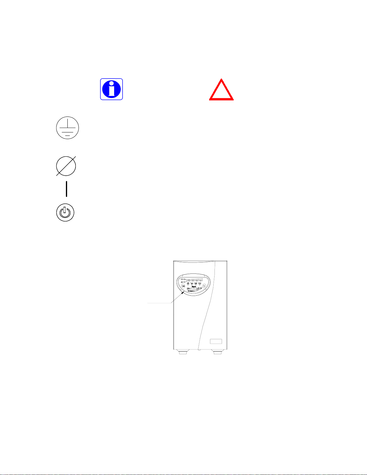
2-3 Annotation and symbol
The two signs shown on the manual indicating important instruction need to be followed.
Read before Operation Maybe Dangerous/Follow Instructions
PROTECTIVE GROUNDING TERMINAL: A terminal which must be
connected to earth ground prior to making any other connection to the
equipment.
This symbol indicates the word “phase” .
This symbol indicates t he principal on/off switch is in the “ON” position.
This symbol indicates the principal on/off switch is in the “STANDBY”
position.
2-4 FRONT PANEL
!
Operation panel
Fig 2-1.1 Front Panel for 700VA or 1KVA
8
Page 10
DELTA DOC CENTER
Operation Panel
SHEET 10 TO 11
Fig 2-1.2 Front Panel for 2KVA or 3KVA
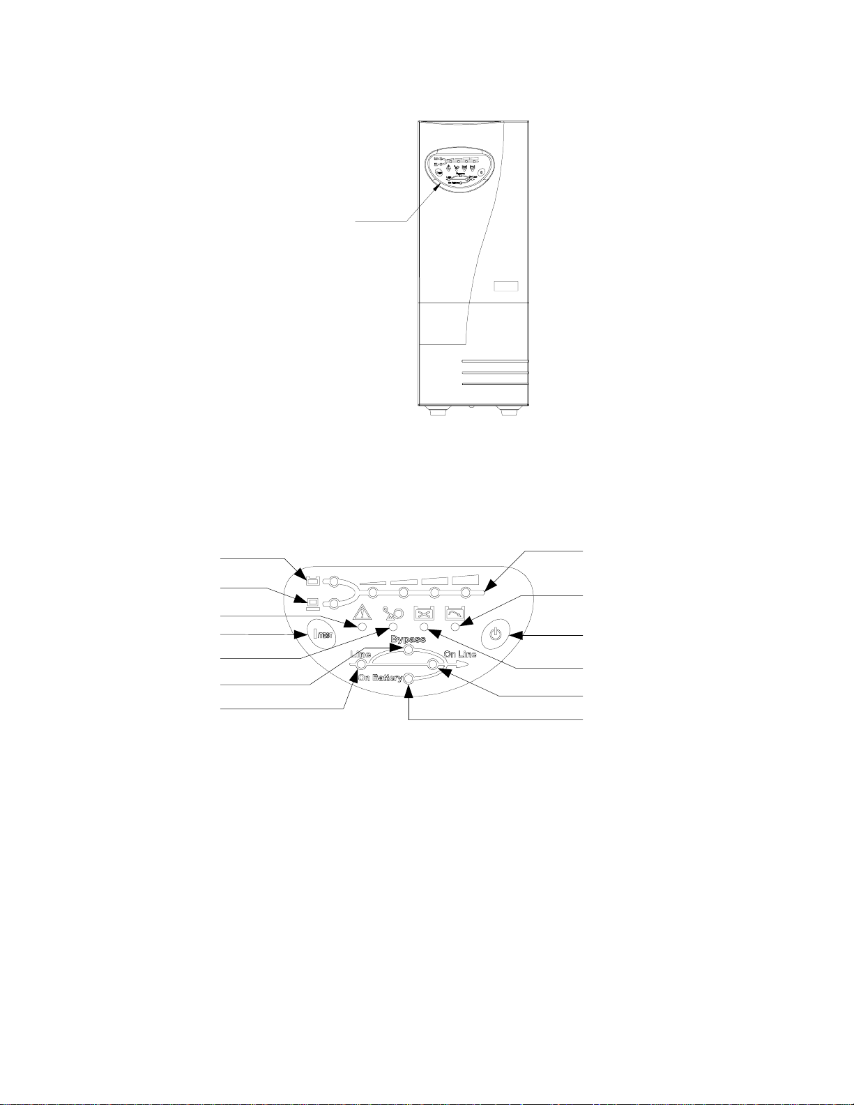
2-5 OPERATI O N PANEL
B. 6
B. 7
B. 11
A. 1 A. 2
B. 10
B. 1
B. 2
Fig 2-2 Operation Panel
OPERATION PANEL
A. Button:
1.
1/TEST:
function in “
for silence.
2. 0: The button is used for turning off UPS.
B. LED display:
The button is used for turning on the UPS, it also can perform the test
ON-LINE mode
”. In backup mode, this button can turn off the buzzer
B. 5
B. 8
B. 9
B. 3
B. 4
1.
Bypass:
The LED indicates UPS in “
BYPASS mode
9
”.
Page 11

DELTA DOC CENTER
2.
SHEET 11 TO 12
3.
4.
The LED indicates the condit ion of UPS input line. If the input voltage is too
Line:
low, too high or out of frequency this LED will flash. When line is blackout or ultra
high voltage (>150Vac for 100-series, >300Vac for 200-series), this LED will light
off.
ON Line:
ON Battery:
internal batteries supply power.
The UPS is running in “
The UPS is running in “
ON-LINE mode
ON-BATTERY mode
”.
” (backup mode), the
5.
Level LEDs:
”or UPS load percentage in “
mode
6.
Battery:
7.
Load:
8.
Battery low:
9.
Battery replace:
replace the batteries.
“Level LEDs” shows the current battery capacity when the LED lights up.
“Level LEDs” shows the UPS load level when the LED lights up.
The four LEDs indicates the battery capacity in “
ON-LINE mode
The LED indicates the battery in ba ttery low condition.
The LED indicates the batteries are weak and suggest the us er to
”.
ON-BATTERY
10.
Overload:
UPS will transfer to “
user.
The LED indicates UPS’ load exceed the rating, after a limited period, the
BYPASS mode
11.
Fault:
fault message when UPS is in “
a site wiring fault from AC power.
The LED indicates that the UPS is fault. This LED also shows a site wiring
” and the LED will still light on to alarm the
STANDBY mode
10
”. It will warn the user that UPS has
Page 12

DELTA DOC CENTER
SHEET 12 TO 13
2.6 REAR PANEL
The rear panel is explained as follows: (Pleas e refe r to fig 2-3, 2-4)
4.
1.
2.
3.
Fig 2-3 700VA, 1KVA
RATING LABEL
BARCODE
6.
5.
9.
7.
4.
9.
9.
4.
6.
6.
5.
5.
7.
8.
1.
2.
1.
3.
1.
Fig 2-4 2KVA, 3KVA
1. OUTPUT RECEPTACLES or TERMINAL
load via these receptacles and terminal. There are several kinds of output connector
for different demands, like:
NEMA 5-20R type
NEMA 5-15R type
IEC320 type
AUSTRALIAN type
: The UPS supplies AC power to the
7.
2.
3.
11
Page 13

DELTA DOC CENTER
SHEET 13 TO 14
2. I/P BREAKER
3. INPUT SOCKET or TERMINAL
the socket or terminal.
4. SNMP SLOT
network.
5. TVSS (Transient Voltage Surge Surppressor) (RJ-45/RJ-11 SURGE
PROTECTOR)
spike traveling form telephone or network line.
6. COMMUNICATION INTERFACE (RS-232/DRY CONTACT)
port is used to communicate PC and UPS. Please refer to section 8 for more
information.
7. Fan
8. Circuit Breaker
9. External Batteries Connector
: DC fans for cooling purpose.
extend back up time.
: This is used to prevent high input current from the UPS.
: AC input utility power supplies to the UPS via
: A SNMP adapter can be plugged in this port for managing UPS on
: These connectors are used to prevent damage from surge, noise and
: The communica tion
: Used to protect UPS from output overload.
: Used for connecting external battery cabinets to
12
Page 14

DELTA DOC CENTER
{
SHEET 14 TO 15
3. INSTALLATION
3-1 Unpacking
z
Please read this user manual bef ore ins talling the UPS.
z
This UPS contains batteries which are potentially hazardous to user, even
when the UPS is not connecte d to the utility power.
z
Before unpacking the UPS, check the packing box. If there are any visible
damage, contact your dealer at onc e.
-This unit is to operate by any individuals with previous training.
-This unit should be installed by service personnel.
3-2 Before Installation
z
Avoid exposing the UPS to direct sunlight or other heat source. The UPS
should be facing awa y from direct sunlight glare.
z
Choose a well-ventilated area to position your UPS to allow adequate
dissipation of heat .
z
Ensure the UPS surrounding area is clean and free from moisture .
z
Do not put heavy objects on the cable or power cord.
3-3 Installation
Notice:
- AC output need a disconnect device such as a breaker which has to be provided by
others.
- The wire length of output power cord connected to the output receptacle or pressure
terminal should be less then 10 meters .
- The UPS provide with pressure terminal connector for field installed wiring, the
terminal connector should be applied a 13.8 lb-in (1.554 N-m)of tightening torque.
- The over current protection and short ci rcuit protection for the AC output is provided
by internal circuits of UPS and breaker.
- Concerning about the battery voltage, ambient temperature and other specifications of
the UPS, please refer to the speci fication section of this manual.
- Servicing of batteries should be performed or s upervised by personnel knowledgeable
of batteries and the required precautions.Keep unauthorized personnel away batteries.
- When replacing batteries, replace with the same type and number .
1. Connecting to utility power (Refer to fig 3-4)
If input type is socket type
(1) Connect the IEC plug of power cord to the IEC 320 connector on the UPS.
13
Page 15

DELTA DOC CENTER
{
SHEET 15 TO 16
{
{
{
{
{
(2) Plug the other end of the power cord into a two-pole, three-wire, grounding
receptacle only. Avoid using exte nsi on cords and adapter plug.
If input type is te r minal type
(1) Be sure to utilize UL1015#12 AWG WIRE for GES302N11XX model and
UL1015#10 AWG WIRE for GES202N11XX model for power connection.
(2) Connect one end of L,N,G strings to t hose of the terminal block and the other end
to those of the switch box (L-L, N-N, G-G).
Avoid using extension cords and adapter plug from UPS.
Turn on the input breaker (if the breaker can be turned on) on the rear pa nel of
UPS.
After that, the fan (in rear panel) will run and all LEDs will light for about 2-3
sec. Meanwhile the CPU inside the UPS setups the initial parameters. User
also can check whether all LEDs are normal or not. The UPS is set in
“
STANDBY mode
the line LED shows AC utility status. Shown as fig 3-1.
” initially, after a ‘bee’ is heard, the load LED lights on and
Fig 3-1 Stand-By Mode
2. Checking the site wiring fault LED (If the function is availa ble)
After the UPS is plugged in , check the site wiring fault LED ( fault LED in
“
STANDBY mode
this LED flashes. Shown as fig 3-2.
”). If the UPS is plugged i nto an improper wired AC power outlet,
Fig 3-2 Sit e Fa u l t
The detection of site wiring fault includes missing ground, hot-neutral polarity reversal
and overloaded neutral circuit. If it lights up, unplug the UPS and have the site wiring
checked by qualified electrician.
14
Page 16

DELTA DOC CENTER
{
SHEET 16 TO 17
{
{
{
{
3. Charging the battery
The battery charger of the UPS automatically charges the battery whenever the power
cord of UPS is connected to a acceptable utility power.
When UPS is running for the first time, charge the UPS for at least 6 hours to ensure
batteries inside are fully charged before operation.
You may im mediately use the UPS wit hout having to wait for the bat teries to be fully
charged. Howe ve r, it is adv isa ble n ot to do t hi s as UPS will have a s ho rte r b ac k -up t ime
than expected if s uch action is ta ken.
Connecting the battery bank
1. Utilize the battery connection cable packed with the battery bank.
2. Connect on one end of the cable to the external battery connector of UPS, and the
other end to that of t he battery bank.
3. Warning: For safety reason, the manufacturer suggests that ONE UPS
CONNECTS AS MANY AS FIFTEEN EXTERNAL BATTERY BANKS.
Fig 3-3 UPS Connected to External Battery Bank
4. The battery banks should be i nst alled by service personnel.
A. According to UL 1778 safety requirement: in order to remove the battery
power cord emergently, please plug in the powe r cord directly.
B. According to EN50091-1-1 safety requirement: bes ide pluggin g in the bat tery
power cord, the battery power cord need to be fixed with the screws.
4. Connecting the load
Calculate power consumption of your loads to ensure that t he overload condi tion will
not happen.
Plug the power co rd of th e e qu i pme n t into the output rece ptacle s on the rear panel of the
UPS.
15
Page 17

DELTA DOC CENTER
{
SHEET 17 TO 18
{
{
{
Turn on the equipment connected to the UPS.
Caution: Do not connect a laser printer to the UPS.
Caution: Do not connect the UPS from genertor.
!
5. Connecting the RS-232/Dry contact
Connect the interface signal cabl e between the
panel of UPS and COM1 or COM2 of computer if necess ary.
RS-232/Dry contact
port on the rear
The D-sub 9 connector can work as a
depending on the type of cable and software used. Refer to section 8 for more
information.
Dry contact
or
RS-232
communication port
(1)
(2)
(3)
Fig 3-4.1 UPS Connection for 700VA or 1KVA:
(1) RS-232/Dry contact cable. (2) Provides power to PC. (3) Connected to utility power.
16
Page 18

DELTA DOC CENTER
SHEET 18 TO 19
(1)
(2)
(3)
Fig 3-4.2 UPS Connection for 2KVA or 3KVA:
(1) RS-232/Dry contact cable. (2) Provides power to PC. (3) Connected to utility power.
17
Page 19

DELTA DOC CENTER
SHEET 19 TO 20
4. OPERATION
4-1 Cold start when utility is not present
Even when there is no utility power, you can still turn on the UPS. Just press the
button and hold for one second, the UPS wi ll start up after you hear a “bee”. The battery
LED and on-battery LED will light on and the UPS runs on “
Shown as fig 4-1.
Fig 4-1On Battery Mode
ON-BATTERY mode
1/TEST
”.
4-2 Turning “ON” the UPS
When the utility power is accept able for the UPS, you can normally turn on the UPS after
pushing the
LED will extinguish after shortly light on. Whe n the on-line LED lights on, the UPS is
running on “
1/TEST
ON-LINE mode
button and hold a few seconds until a “bee” is heard. The bypass
”. Shown as fig 4-2.
Fig 4-2 On-Line Mode
4-3 Turning “OFF” the UPS
Push the 0 button for turning off the UPS, when a “bee” is heard release your press. After
a few seconds the UPS is off.
The UPS will keep charging when UPS is in “
button has been pressed. To fully turn off the UPS, it is advised to unplug the power cord.
Refer to fig 3-1.
STANDBY mode
18
” even though the 0
Page 20

DELTA DOC CENTER
{
SHEET 20 TO 21
{
4-4 UPS self-test
If press the
shift to “
(Shown as fig 4-4.) The self-test function will check the condition of the battery. After
self-test is finished and te st is O.K, the UPS will return to “
1/TEST
ON-BATTERY mode”
button when the UPS is in “
and automatically perform a self-test for about 10 seconds.
Fig 4-4 UPS Self-Test
ON-LINE mode”
ON- LINE mode”
, it will make the UPS
.
4-5 Silence function
The buzzer can be turned “On” or “Off” by toggling the
in “
ON-BATTERY mode”
.
1/TEST
button when the UPS is
4-6 If certa in ab normal c ondit ion o ccurs , the UPS will s end t he fol lowi ng
messages:
ON-BATTERY mode:
LED will light on, buzzer beep half second every 2 seconds and then the UPS will
start supplying power to load through bat teries. Shown as fig 4-5.
When the UPS is in “
ON-BATTERY mode”
, the on- battery
Fig 4-5 On-Battery Mode
OVERLOAD:
LED will light on and buzzer continuous beeping to alarm the use r. The user should
unplug some uncritical loads to release the overload condition. Shown as fig 4-6.
If the load exceeds the UPS rating, after a limited period, the overload
Fig 4-6 Overload and UPS turn into Bypass
19
Page 21

DELTA DOC CENTER
{
SHEET 21 TO 22
{
{
BATTERY REPLACE:
be replaced. When the microprocessor in the UPS detects a battery fault, the UPS
alarm will give out three beeps. Each beep lasts for 0.5 seconds and interrupted by an
interval of 0.5 seconds. After the initial 3 beeps, the alarm will continue to sound
every one hour. Shown as fig 4-7.
BATTERY LOW:
the batteries. When batteries reach a low level condition, the UPS alarm will beep
half second every 1.5 seconds until running out of battery ca paci ty. Shown as fig 4-8.
This LED function is to alert user that the batteries should
Fig 4-7 Battery Replace
This function is to inform user the remaining power c apacity of
Fig 4-8 Battery Low
SHORT CIRCUIT:
“
ON-BATTERY mode
as the short circuit is happened, the fault LED will light on and the UPS a larm will
sound continuously. When remove short circuit, the UPS output will recover. If short
circuit is happened in “
input breaker and shut down. Shown as fig 4-9.
When the output of the UPS shorts in “
”, the UPS will shut down (without output voltage). As soon
BYPASS mode
”, the UPS will protect itself by tripping the
ON-LINE mode
Fig 4-9 Short Circuit
20
” or
Page 22

DELTA DOC CENTER
{
SHEET 22 TO 23
{
{
4-7 UPS internal fault
If the following conditions occur, the UPS fails. At this time the UPS will transfer to
“
BYPASS mo de
If utility is too low or too high the UPS output will be disabled. For fault messages, please
refer to the troubleshooting (section7) of this manual.
When the UPS inner component overheat, the UPS will protect itself by
thermo-switches. This status i s so-called “
When under (or over) voltage is happene d in the UPS out put. This kind of fault will
be detected by the microprocessor in the UPS and is so-calle d “
When under (or over) bus voltage is happened in the UPS and is so-called “
U.V.P
”. The bypass LED and fault LED will light on a nd alarm continuously.
” (“
Bus O.V.P
”).
”
O.T.P
U.V.P
” (“
O.V.P
”).
Bus
4-8 Storing the message into EEPROM
After low battery shutdown or fault, the UPS will store the message into EEPROM. The
UPS will auto-restart when the utility power is recovered. Shown as fig 4-10.
Fig 4-10 Store message in EEPROM
4-9 Derating power
In the range of 130Vac to 160Va c(or 65-80Vac), the UPS load capaci ty will decrease. This
function provides a wider operating power voltage range.
4-10 Programmable output (Optional)
User can use the monitori ng s of tware to control which receptacle can deliver power.
21
Page 23

DELTA DOC CENTER
SHEET 23 TO 24
5. MAINTENANCE
z
Normally, the life of battery is 3 years. But extreme operat ing condition and
environment may shorten its life-span.
z
To re place batteries, contact qualified personnel.
z
When UPS has been unused for a period of time, the ba tteries will discharge
slightly. It is recommended to charge the UPS once every 3 months.
z
Use a vacuum cleaner to get rid of any dust that may rest on the opening of
the fan.
z
Unplug the UPS when it is not use d for a long time.
z
When cleaning the plastic case or front panel, only use a soft, dry cloth. If
the case or front panel is very dirty, use a neutral, non-abrasive detergent. Do
not use alcohol or ammoni a based solutions.
z
When moving your UPS, always handle it with care.
z
Avoid s pilling liquid on the UPS.
z
The equipment should be repaired and installed by individuals with previ ous
training.
When installing this equipment, it should be noted that the leakage current of the UPS and
its loads must not exceed 3.5mA in total for safet y.
22
Page 24

DELTA DOC CENTER
SHEET 24 TO 25
6. PLACEMENT
To stably install the UPS, the 2,3KVA must add stands to support themselves. The
installation method is as shown below:
Fig 6-1 Erect the UPS with supporting stands
23
Page 25

DELTA DOC CENTER
SHEET 25 TO 26
7. TROUBLESHOOTING
Problem Possible Cause Solution
ON/TEST button is not pushed.
Battery low shut down and
UPS is not turned on.
(No alarm, No LED lights)
UPS does not provide
expected back-up time.
All LEDs light on. Internal UPS fault.
“REPLACE BAT TERY”
LED lights on.
PC-UPS communication
does not work properly.
utility is abse nt.
The rear panel input circuit
breaker is tripped. (Button is
tripped out)
UPS fault.
Batteries inside the UPS are
not fully charged.
UPS is overloaded.
Batteries are weak.
Charger fault or other reason. Call for service.
Weak batteries.
Incorrect transmission speed.
Incorrect RS-232 connection.
Press the 1/TEST button to
turn on the UPS.
(Refer section 4 to turn on the
UPS.)
Waiting f o r line recovery.
1. Reduce some loads connected
to the UPS.
2. Reset the circuit breaker.
(Push button in)
Call for qualified service
personnel if above actions do
not solve the problem.
Recharge the batteries for at
least 8 hours.
Remove some unnecessary
loads.
Batteries weak faster when
used often or operating at
higher temperature.
If the battery is near the end of
its life, call for servi ce personne l.
Replace the battery even if the
REPLACE BATTERY LED
does not light.
1. Turn off UPS.
2. Call for service .
1. Recharge the ba tteries for at
least 8 hours.
2. If problem remains Call for
service personnel to, replace
the batteries.
Re-test after using another
different transmission speed.
Refer to communication interface
(Section 8) of this manual
Re-connect the UPS with
COM1 / COM2 on PC again.
UPS operates on battery
even though the line is in
normal operating condition.
Site wiring fault LED
(fault led flas h).
No incoming utility. Check input power connection.
The rear panel input circuit
breaker is tripped. (Button is
out).
Very high, low or distorted
utility voltage.
Wiring error such as reversed
hot/neutral.
24
1. Reduce some loads connected
to the UPS.
2. Reset the circuit breaker.
(Push button in)
Have qualified electrician check
the input voltage.
Get wiring checked by electrician.
Page 26

DELTA DOC CENTER
SHEET 26 TO 27
UPS over temperature.
The exhaust fans and ventilation
grills may be obstructe d.
The environment temperature
exceeds 40
o
C (104oF).
Choose a well-ventilated area
to position your UPS to allow
adequate dissipati on of heat.
Position your UPS in cooler
area.
“FAULT”LED lights on,
alarm beeps
“OVERLOAD” LED
lights on and buzzer
beeps continuously.
FAULT MESSAGE
Following information indicates various symptoms .
Use this information t o det e rmine what factors cause the problem .
1. Alarm will sound to alert user that the UPS requires attention.
2. One or more additional load/battery leve l LED indicators will illuminate to provide a
diagnostic aid to the operator, described as below:
Output temperature protect D & C LEDs light on
Output over voltage protect D LED light on
Output under voltage protect C LED light on
Bus over voltage protect B LED light on
Bus under voltage protect A LED light on
UPS failure. Call fore service engineer.
Overloaded. Remove some critical load.
ABCD
Fig 7-1
In case that failure is happened and utility is too low or too high, the UPS output will
disable and the bypass and line led will flash.
ABCD
Fig 7-2
If problem continues, contact your local dealer.
25
Page 27

DELTA DOC CENTER
8. COMMUNICATION INTERFACE
SHEET 27 TO 28
The UPS provides
proper UPS management software and cable, the UPS can be managed over
LAN/intranet/internet environment. The pin assignment of the D-sub 9 connector is
defined as follows:
PIN
1 Low battery(Open collector)
2 UPS TxD(typical RS-232 level)
3 UPS RxD(typical RS-232 level) Remote shutdown(5~12V)
4 Reserved for PNP
5 GND GND
6 Reserve d for PNP Reserved
RS-232
and
Dry contact
protocols in one D-sub 9 connector. Using
ASSIGNMENT DESCRIPTION
RS-232 Dry Contact
7 Reserve d for PNP Reserved
8 Utility Fail(Open collector)
9
Open Collector
6789
12345
Fig 8-1 Pin Assignment Fig 8-2 Open Collector Circuit
Maximum voltage and current on pin 1,8 is 30VDC, 10mA.
GND
8-1 RS-232
Pin2 : PC receives line
Pin3 : PC transmits line
Pin5 : Signal ground.
Pin4,6,7 : Reversed for plug and play function.
RS-232
RS-232
data from UPS.
data to UPS.
26
Page 28

DELTA DOC CENTER
SHEET 28 TO 29
The
RS-232
1) Monitoring charger status
2) Monitoring battery status and condition
3) Monitoring inverter status
4) Monitoring UPS status
5) Monitoring the utility status
6) Providing the power switch function for c omputer to turn on/off the utility on schedule
for power saving
7) Adjustable Transfer voltage
The UPS data is provided at 2400 bps baud rate and made up of 8-bit, 1 stop -bit and no
parity bit. All informa tion is encoded in ASCII form at.
communication port provides the following functions:
HARDWARE:
BAUD RATE----------------2400 bps
DATA LENGTH------------8 bits
STOP BIT--------------------1 bit
PARITY----------------------NONE
CABLING:
Standard D-sub 9 cable (UPS side: male, PC side: fema le)
8-2 Dry Contact
Pin1 : The pi n is normally open. When battery low, pin1 and pin5 are connected
via photo coupler.
Pin3 : The UPS will shut down when a high level (5~12V) sustained for at leas t
3.8 seconds is applied.
Pin5 : Signal ground.
Pin6,7 : Reserved.
Pin8 : T he pin is normally open. When utility fails, pin8 and pin5 are connected
via photo coupler.
CABLING: The user must use the special cable. The connection is described as follows:
PC (female) UPS (male)
Pin1------------------Pin1 (battery Low)
Pin3------------------Pin5 (GND)
Pin4------------------Pin3 (Shutdown)
Pin7------------------Pin6
Pin7------------------Pin7
Pin8------------------Pin8 (AC Fail)
The communication port at the back of the UPS may be connected to a computer. This
port allows the computer to monitor the UPS and control the operation of the UPS in
some cases.
27
Page 29

DELTA DOC CENTER
SHEET 29 TO 30
Its major functions normally some or all of following:
To broa dcast a warning when power fails.
To c lose the files before the battery is exhausted.
To turn off the UPS computers.
Some computers may have a special connector to link this communication port, or require
a special plug-in card, or need a special UPS monitoring soft ware. Contact your dealer for
details of different interface kits.
Caution:
Every time when you connect your UPS and computer, please make sure the utility exists.
28
Page 30

DELTA DOC CENTER
SHEET 30 TO 31
Technical specifications
Model
Capacity
Input
Output
Outlet
Battery
Transfer Time
LED
Interface
Environment
Safety
Approval
Others
Appearance
700VA/560W 1KVA/800W 2KVA/1600W 3KVA/2400W
Rated Voltage
Voltage Range
Frequency
Power Factor
Voltage
Frequency 50Hz/60Hz
Voltage Regulation +2%
Frequency Accuracy +0.05 Hz
Wave Fo rm Pure Sine Wave
Transient Response +5% (10%∼90% Linear Load)
THD
Overload Capacity 105%-125% for 3mins; 125%-150% for 30secs; >150% for 1sec
Crest Factor 3:1
Efficiency (AC-AC)
Receptacle
Battery Voltage 36 V 36 V 72V 72V
Battery Type (Lead acid) 12V/7Ah 12V/9Ah
Back-up Time (Typical) 8mins (420W) 5mins (700W) 5mins (1400W) 5mins (2000W)
Recharge Time 8 Hours After Complete Discharge to Recover 90%
Transfer Tim e Zero
LED Status
Alarm Buzzer
DB9 RS232/Dry Contact
SNMP Slot Internal
Noise (At 1 Meter) 40dBA 42dBA 42dBA
Operating Temperature
Humidity 0%~--90%(Non-Condensing)
Safety
EMC
Lightning IEEE 62.41 Category A
Battery Start Yes
Extended Battery Bank Yes (Optional with Long Time)
Long Time Model Yes (Optional)
Dimension(W×D×H)
Weight
Typical 15kg/33 lb 15kg/33 lb 29kg/63.9 lb 29 kg/63.9 lb
Long Time 8.1kg/17.8 lb
GES701N GES102N GES202N GES302N
100V,110V,120V
200V,208V,220V,230V,240V
80V∼138V(Full Load);65V~80V(70% Load)
160V∼275V(Full Load);130V~160V(70% Load)
50Hz/60Hz (±4.8 Hz)
≥
0.97
100V,110V,120V
200V,208V,220V,230V,240V
≤
3%(Li near Load); ≤6%(Computer Load)
≥
86%
NEMA5-15R×2×2
IEC320×2×2
On-line、Bypass、On-battery、Overload、Battery Low、Fault、Battery
140x363x242/mm
5.5x14.2x9.5/inch
≥
87%
Replace、Battery L evel、Load Level
0~40℃
UL/cUL
TUV/GS
FCC Class A(2,3KVA)/B(1KVA)
CISPR PUB 22 Cla ss B; TUV/EMC; CE
140x363x242/mm
5.5x14.2x9.5/inch
8.1㎏/17.8 lb
≥
87%
NEMA5-15R×2×2
IEC320×4×2
140x422x373/mm
5.5x16.6x14.7/inch
15.2kg/33.5 lb 15.2kg/33.5 lb
≥
87%
140x422x373/mm
5.5x16.6x14.7/inch
All specifications are subj ect to change without prior notice.
29
Page 31

SHEET 31 TO END
 Loading...