

Page 1
4886
Part Number Amplier Name
Revision 0.a Release Date April 2008
Revision Notes Initial release
LA2-1-1025-33
Technical Specications Summary
Frequency Range:
P1dB:
Class:
Supply Voltage:
This ultra broadband class A amplier operates from below 1 MHz to over 1 GHz. Using all gold
metallized LDMOS transistors and a stable design, this compact, high performance laboratory amplier
will nd use in many applications.
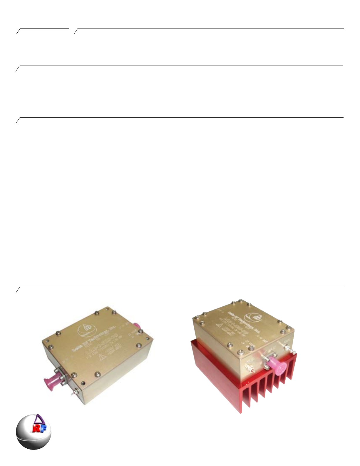
The LA2-1-1025-33 is offered as a standalone unit requiring the customer to mount to a modest
heat sink, or we offer this with a heat sink. A disable line is option.
1 - 1025 MHz
2 Watts CW
A
28 V DC
Gain:
Efciency:
Temperature Range:
Max VSWR:
33dB
12%
0 to 50°C
10:1
Amplier General Description
Delta RF Technology, Inc.
High Power RF Ampliers and Accessories
350 South Rock Boulevard • Reno • NV • 89502 • USA
Amplier Picture
Phone +1.775 DELTA RF [775 335 8273]
Fax +1.775 DELTA FX [775 335 8239]
website: http://www.drft.com
email: sales@drft.com
Page 2

4886
Parameter Min Typ Max Units Notes
Frequency 1 1025 MHz
P1dB 1.5 2 W, CW
Psat 3 W, CW
Power Input 1 mW, CW For 2W output
Gain 32 33 dB
Noise Figure 3.5 4 dB
Vsupply 24 28 V, DC
Drain Current 0.5 0.70 A, DC
Efciency 12 %
Input VSWR 1.5:1
Insertion Phase Variation 5° ° Unit to unit
Gain Variation ±2 dB Unit to unit
F2 Second Harmonic -45 dBc
F3 Third Harmonic -45 dBc
Baseplate Operating Temperature 0 40 °C High temperature at 3:1 VSWR Maximum
LA2-1-1025-33
Electrical Specications
Amplier is rated for this power into 1:1 load only
Physical Dimensions
All specications valid for 50 Ω output load, V
Parameter Value Units Notes
Maximum Operating Voltage 30 V, DC
Stable Operating Voltage 24 - 30 V, DC
Maximum Bias Current, Q100 0.065 A, DC Factory set, no user adjustment
Maximum Drain Current, Q101 0.65 A, DC Factory set, no user adjustment
Load Mismatch Survival 10:1 Up to 40°C
Storage Temperature -40 to 85 °C
Maximum Operating Baseplate Temp 50 °C Max 3:1 VSWR, 2W CW
♦ Amplier Disable - optional
♦ SMA Female connectors RF INPUT and RF OUTPUT
♦ Solder connections for Vsup, Ground, Disable
= +28VDC, Idq = 0.5A
sup
Features, Auxillary Functions
Absolute Maximum Ratings
Page Number 2
Page 3

4886
LA2-1-1025-33
Mechanical Specications
Page Number 3
Page 4

4886
P1dB - Watts
0
0.5
1
1.5
2
2.5
3
3.5
0 200 400 600 800 1000
Frequency - MHz
P1dB - Watts
Gain 2W
0
5
10
15
20
25
30
35
40
0 200 400 600 800 1000
Frequency - MHz
Gain - dB
Gain 2W
0
5
10
15
20
25
30
35
40
0 200 400 600 800 1000
Frequency - MHz
Gain - dB
Harmonics
0
10
20
30
40
50
60
0 200 400 600 800 1000
Frequency - MHz
Harmonics - dBc
F2 Second Harmonic
F3 Third Harmonic
LA2-1-1025-33
Graphs and Charts
Graph 1. Gain, 2W Graph 2. P1dB
Graph 3. Gain, 1W Graph 4. Harmonic Performance
All data taken at +28VDC
Page Number 4
Page 5

4886
Attach amplier to heatsink using thin layer of thermal compound. The amplier will produce approximately 20W of heat, so a
medium size heatsink will be adequate - a heatsink with approximate dimensions 2 x the area of the lab amp and approx 1.0”
deep. A smaller heatsink may be used if any airow is used.
Attach RF Input and RF Output using SMA Female connectors and tighten. Install ground wire and Vsup using solder connections - make sure to attach positive wire to Vsup terminal. If optional disable is ordered, install using disable terminal on input
side of amplier.
To operate, apply Vsup and amplier is ready to operate.
LA2-1-1025-33
Integration and Operating Instructions
Page Number 5
Page 6

4886
Ordering Information:
Order Code Description DRFT Reference
LA2-1-1025-33 2W Broadband Laboratory amplier module 4886
Options
-A12 Heat Sink Option 0202
-A13 Heat Sink Option with DC Fan, pre wired 0203
-A14 Ruggedized for vibration 0204
-T2 Extended Burn In 0271
-T3 Extended Data Collection 0272
Standard Pallet Options:
SMA Female Connectors, Input and Output. Stainless Body, Gold Center pin, 4-hole SMA bolted to pallet amplier edge through bottom two holes located at ampliers RF IN and RF OUT
locations. All stainless steel hardware.
Enclosure- all aluminum machined enclosure available for most pallet ampliers. Alodyned aluminum, alloy 6061-T6. SMA Female input and output RF connectors. Supply voltage and ground
through solder / feedthrough connections. Module must be bolted to appropriate heatsink.
Heat Sink - aluminum extruded heat sink, black anodized. Pallet amplier or module will be bolted to heatsink. Customer will be required to provide adequate airow.
Heat sink with fan - aluminum extruded heat sink as above, with included fan bolted to push air through the heat sink. Depending on heat requirements, a second fan may also be provided on
the output of the unit.
Ruggedized - all screws have threadlocking compound applied, and all ying components are staked and attached to base. Designed to withstand MIL-STD-810E 514.4 Category 8.
LA2-1-1025-33
Ordering Information
Testing Options:
Standard - includes power test and brief burn - in under laboratory conditions. Printed test report gives graph of Gain and Input Return Loss at rated P1dB and Voltage Conditions. Report
shows pass/fail critera. All ampliers include this test.
Extended burn in - 8-hour burn in at P1dB with standard test run at completion. Unit is monitored during test and any discrepancy reported. Standard test data is included.
Extended data collection - Standard data is run and included. Detailed data is taken point by point giving the customer 25 - 70 frequency points, depending on the amplier model. For each
frequency point, data is generated to include gain, input power, input return loss, current, second harmonic, third harmonic, efciency, audio distortion.
Other tests available - Vibration, Temp cycling, Shock. Please inquire.
The specications contained herein are subject to change without notice. Delta RF Technology, Inc. assumes no liability for the use of this information.
This data sheet and contents are the property of Delta RF Technology, Inc. © Delta RF Technology, Inc. 2008.
Page Number 6
 Loading...