

Delta Breez SLM50-110-C, SLM80-110D-C, SLM50-110LED-C, SLM80-110DLED-C, SLM80-110H-C User Guide
Page 1
Installation and Operating Instructions
CEILING/WALL VENTILATION FAN
READ AND SAVE THESE INSTRUCTIONS
GENERAL SAFETY INFORMATION
1. Make sure that the electric service supply voltage is
AC 120V, 60Hz.
2. Follow all local electrical and safety codes, as well
as the National Electrical Code (NEC) and the
Occupational Safety and Health Act (OSH Act).
3. Always disconnect the power source before working
on or near the ventilating fan, motor or junction box.
4. Protect the power cord from sharp edges, oil, grease,
hot surfaces, chemicals or other objects.
5. Do not kink the power cord.
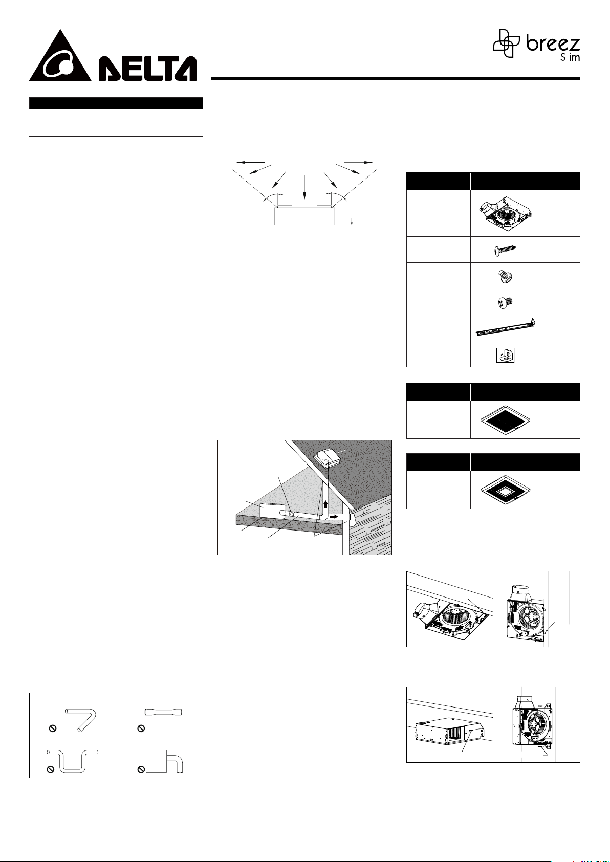
6. Do not install the unit where ducts are configured as
shown in Fig. A.
7. Provide suction parts with proper ventilation.
8. This unit is UL Listed for use over a bathtub or shower
when installed in a GFCI protected branch circuit.
WARN ING
TO REDUCE THE RISK OF FIRE, ELECTRIC SHOCK, OR
INJURY TO PERSONS, OBSERVE THE FOLLOWING:
1. Use this unit only in the manner intended by the
manufacturer. If you have questions, contact the
manufacturer.
2. Before servicing or cleaning unit, switch power off at
the service panel and lock the service disconnecting
means to prevent the power from being switched
on accidentally. When the service disconnecting
means cannot be locked, securely fasten a prominent
warning device, such as a tag, to the service panel.
3. nstallation work and electrical wiring must be
done by a qualified person(s) in accordance with all
applicable codes and standards, including fire-rated
construction.
4. Sufficient air is needed for proper combustion and
exhausting of gases through the flue (chimney) of fuel
burning equipment to prevent backdrafting. Follow
the heating equipment manufacturer’s guideline
and safety standards such as those published by the
National Fire Protection Association (NFPA), and the
American Society of Heating, Refrigerating and Air
Conditioning Engineers (ASHRAE) and local code
authorities.
5. When cutting or drilling into the wall or ceiling, do not
damage electrical wiring and other hidden utilities.
6. Ducted fans must always be vented to the outdoors.
7. If this unit is to be installed over a tub or shower, it
must be marked as appropriate for the application
and be connected to a GFCI (Ground Fault Circuit
Interrupter) –protected branch circuit.
8. Do not use this unit with any other solid-state control
device. Solid-state control device may cause harmonic
distortion, which can cause a motor humming noise.
(Avertissement: ne convient pas à des régulateurs de
vitesse à semi-conducteurs).
9. NEVER place a switch where it can be reached from a
tub or shower.
10. Not to be installed in a ceiling thermally insulated
to a value greater than R50. (This is required for
installation in Canada only).
11. Do not open/disassemble LED light engine.
Turning angle too large Duct shrink
Too many elbows Elbow near the body
Body
Fig. A
CAUTION
1. For General Ventilating Use Only. Do Not Use To
Exhaust Hazardous Or Explosive Materials And Vapors.
2. Not for use in cooking area. (Fig. B)
MODELS: SLM50-110-C, SLM80-110D-C, SLM50-110LED-C, SLM80-110DLED-C, SLM80-110H-C
Page 1.
3. This product must properly connect to the grounding
conductor of the supply circuit.
4. To reduce the risk of injury to persons, install the fan
at least 8.2 feet (2.5m) above the floor.
Cooking area
Do not install above or
inside this area
45°
Cooking
Equipment
Fig. B
45°
oor
ASSEMBLY INSTRUCTION
WARNING: Turn o electricity at breaker box before
beginning installation.
1. Carefully remove unit from carton.
2. Check area above installation location to be sure that
wiring can run to the planned location and that duct
work can be run. Make sure the area is sufficient for
proper ventilation.
3. Inspect duct work and wiring before proceeding with
installation.
4. Before installation, provide inspection and future
maintenance access at a location that will not
interfere with installation work.
5. You may need the help of a second person to install
this fan: one person on the attic side and one on the
room side.
Note: Installations may vary depending on how the
previous bath fan was installed. Supplies necessary for the
installation of your bath fan are not all included. However,
most are available at your local home improvement or
hardware store.
Roof cap
or
(with built-in
damper)
Short piece of exible
duct helps alignment
and absorbs sound
Fan housing
•
Unit must be installed in ceiling to properly sense
moisture.
•
Locate unit only on flat ceilings up to 12 feet high for
proper sensing.
PACKAGE CONTENTS
For all Models:
Part name Appearance Quantity
Fan Body 1
Tapping Screw
(Ø4×25mm)
(Machine Screw
(#8-32x5/16”)
Machine Screw
(M4x6 mm)
Hanger Bar 1
Wiring Cover 1
For the Model of SLM50-110-C, SLM80-110D-C,SLM80-110H-C
Part name Appearance Quantity
Grille 1
For the Model of SLM50-110LED-C, SLM80-110DLED-C
Part name Appearance Quantity
Grille 1
ASSEMBLY INSTRUCTION
Seal gap
around
housing
2~3 ft
straight run
before elbow
Caulk termination
to duct
Proper insulation around the fan to minimize building heat
loss and gain. The ducting from this fan to the outside of
the building has a strong effect on the air flow, noise and
energy use of the fan. Use the shortest, straightest duct
routing possible for best performance, and avoid installing
the fan with smaller ducts than recommended. Insulation
around the ducts can reduce energy loss and inhibit mold
growth. Fans installed with existing ducts may not achieve
their rated air flow.
1. The fan will operate most efficiently when located
where the shortest possible duct run and minimum
number of elbows will be needed.
2. Use a roof cap or wall cap that has a built-in damper
to reduce backdrafts.
3. External timer can be used in conjunction with
single-speed mode only, please contact Delta
Breez customer service and consult with a licensed
electrician for compatibility.
4. External dimmer can be used in conjunction with
LED light model, please contact Delta Breez customer
service and consult with a licensed electrician for
compatibility.
For humidity sensing models only (SLM80-110H-C)
•
Locate unit above (GFCI-protected circuit required) or
within 5 feet of the shower head.
•
Locate unit away from heating or cooling sources
which can affect humidity levels.
•
Do not locate near window. Unit may respond to the
outdoor humidity level.
Installation I
(Ceiling/Wall mount housing with ange)
1. To bend the housing tabs out to 90 degree and make
housing tabs contact the bottom or front of the joist.
Joist
Tabs
Joist
Tabs
2. The housing mounts with 4 screws (Ø4×25 mm).
Screw housing to joist through the round holes in
each mounting flange, then through the other holes.
Joist
Joist
Screw Ø4x25 mm
Screw Ø4x25 mm
Installation II
(Using suspension bracket):
1. The housing mounts with 4 screws (Ø4×25 mm)
Screw housing to joist through the round holes in
each mounting flange, then through the other holes.
2. Insert suspension bracket into the channel on
housing.
6
1
1
Page 2
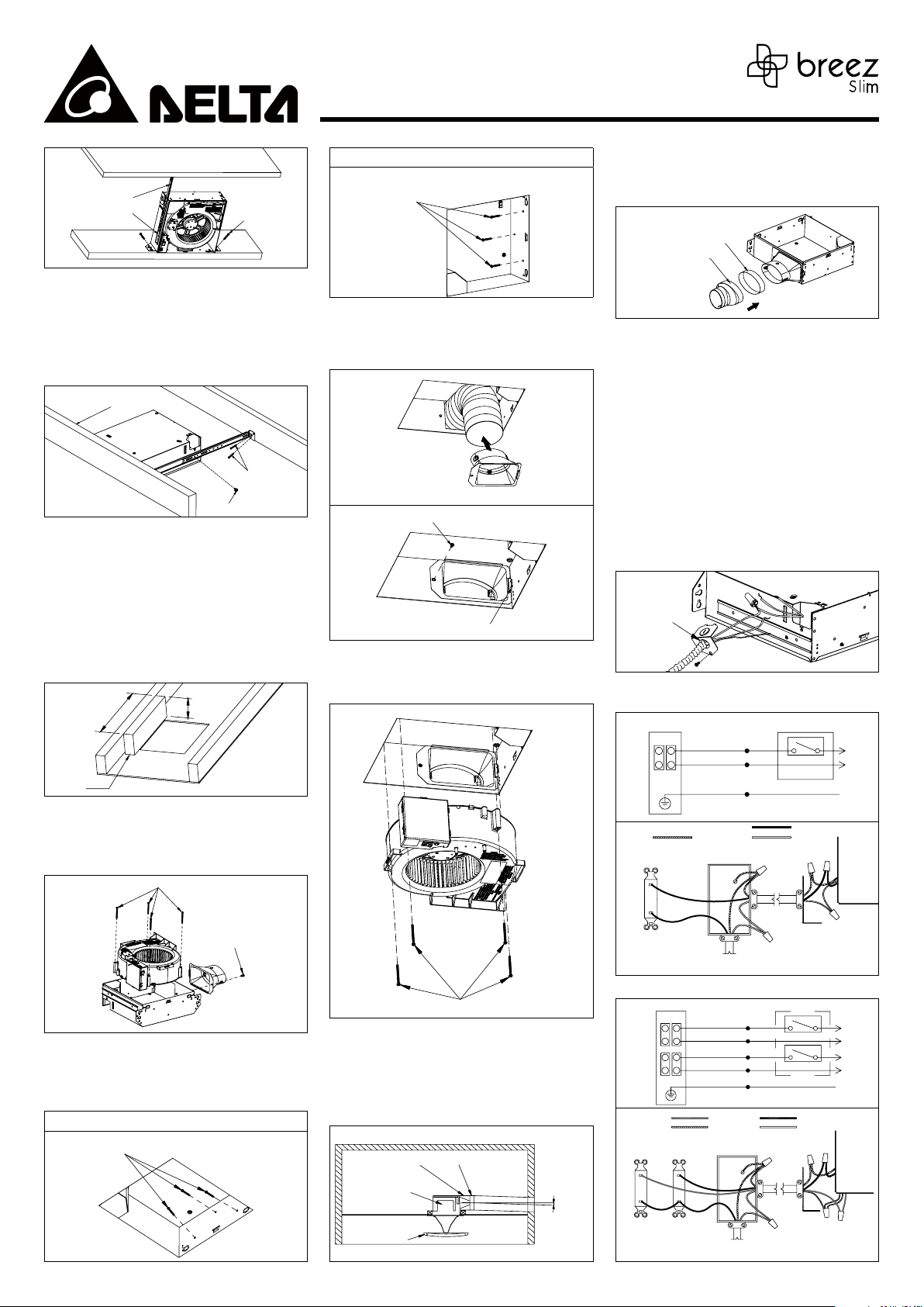
Suspension Bracket
Channel
Screws Ø4x25 mm
MODELS: SLM50-110-C, SLM80-110D-C, SLM50-110LED-C, SLM80-110DLED-C, SLM80-110H-C
Page 2.
WALL MOUNTING
Screws Ø4x25 mm
Connection method for 3” round duct connector
3. 4” Oval to 3” round duct adapter, VFRU-29-10DA (sold
separately).
4. Please follow step “1” and “2” to install.
3. Extend suspension bracket to the width of the joists.
Make sure the fan body is level and perpendicular
with the joist, and flush with ceiling surface.
4. Fasten suspension bracket to joist with tapping
screws (ø 4×25 mm).
5. Secure suspension bracket to housing with screw
(#8-32x5/16”).
Bottom Of Joist
Joist
Joist
Screw Ø4×25mm
Screw #8-32x5/16”
Installation III (Retrot installation):
1. Removing existing fan.
2. Measure the ceiling or wall opening and cut a new
opening to ensure it is large enough to accommodate
the new fan (10 3/4 in. x 11 1/2 in. suggested).A piece
of wood (not provided) may be necessary that is
screwed in from indoor through the ceiling board or
wall. Suggested size is H 4 in. x L 17 in. Position the
screws far enough from the edge of the ceiling board
or wall that it does not crumble and give way.
10 3/4"
4"
11 1/2"
17"
Wood
3. Remove the fan body by release four machine screws
(M4 x 45 mm), unplug all connectors from wiring
panel and then remove duct connector by release
machine screw (M4 x 6 mm).
Screw M4 x 45mm
5.
Do the duct work as below picture and follow “DUCT
CONNECTION” and then fix the duct connector to the
housing inside by using machine screw (M4 x 6 mm).
Pull existing duct into housing
Screw M4 x 6mm
Insert tab into hole in housing
6.
Insert fan body into housing by using four machine
screws (M4 x 45 mm) originally on the fan body and
plug in all connectors.
VFRU-29-10DA
(sold separately)
Tape
CONNECT WIRING
TURN OFF POWER SOURCE.
REVIEW ALL SAFETY PRECAUTION.
1. Follow all local electrical and safety codes, ANSI/
NFPA70.
2. NEVER place a switch where it can be reached from a
tub or shower.
3. Use wire nuts (not provided) and connect house
power cable to ventilating fan as below diagram A.
4. 14 AWG (2.1 mm2) is the smallest conductor that shall
be used for branch-circuit wiring.
5. Use slotted screwdriver to remove a hole onwiring
cover (from parts bag).
6. Push all wires into wiring compartment of units,
use screw(from parts bag) to secure wiring cover to
housing.
A.
Open Hole
WIRING DIAGRAM
1. SLM50-110-C
JUNCTION BOX SWITCH BOX
OFF
ON
POWER SWITCH
BLACK
WHITEGROUND
ON/OFF SWITCH
(purchase separately)
BLACK
WHITE
GREEN
(bare)
SWITCH BOX
L
N
GRD
Screw M4 x 6mm
4. U
sing wire nuts (not provided) connect house
fan wires as shown in “CONNECT WIRING” diagram A.
Insert housing into ceiling or wall opening and secure
housing by using tapping screws (ø 4x25 mm).
CEILING MOUNTING
Screw Ø4×25mm
wires to
Screw M4 x 45mm
DUCT CONNECTION
Connection method for 4” oval duct connector
1. Insert the duct into the duct connector and tape all
ductworks connection to make them secure and air
tight.
2. Install the duct with a gradient 1°~2° to the outside.
Duct Connector
Body
Ceiling
Grille
Tape
Duct
OutsideInside
Gradient
1°~2°
POWER
SWITCH
120 VAC
LINE IN
2. SLM80-110D-C,SLM80-110H-C
JUNCTION BOX SWITCH BOX
BLACK
WHITE
BLUE
WHITE
GREEN
ON/OFF SWITCH
(purchase separately)
POWER
MODE
SWITCH
SWITCH
(bare)
SWITCH BOX
120 VAC
LINE IN
WIRING
PLATE
OFF
ON
POWER SWITCH
HI
MODE SWITCH
BLACKBLUE
WHITEGROUND
WIRING
PLATE
L
N
L
N
GRD
Page 3
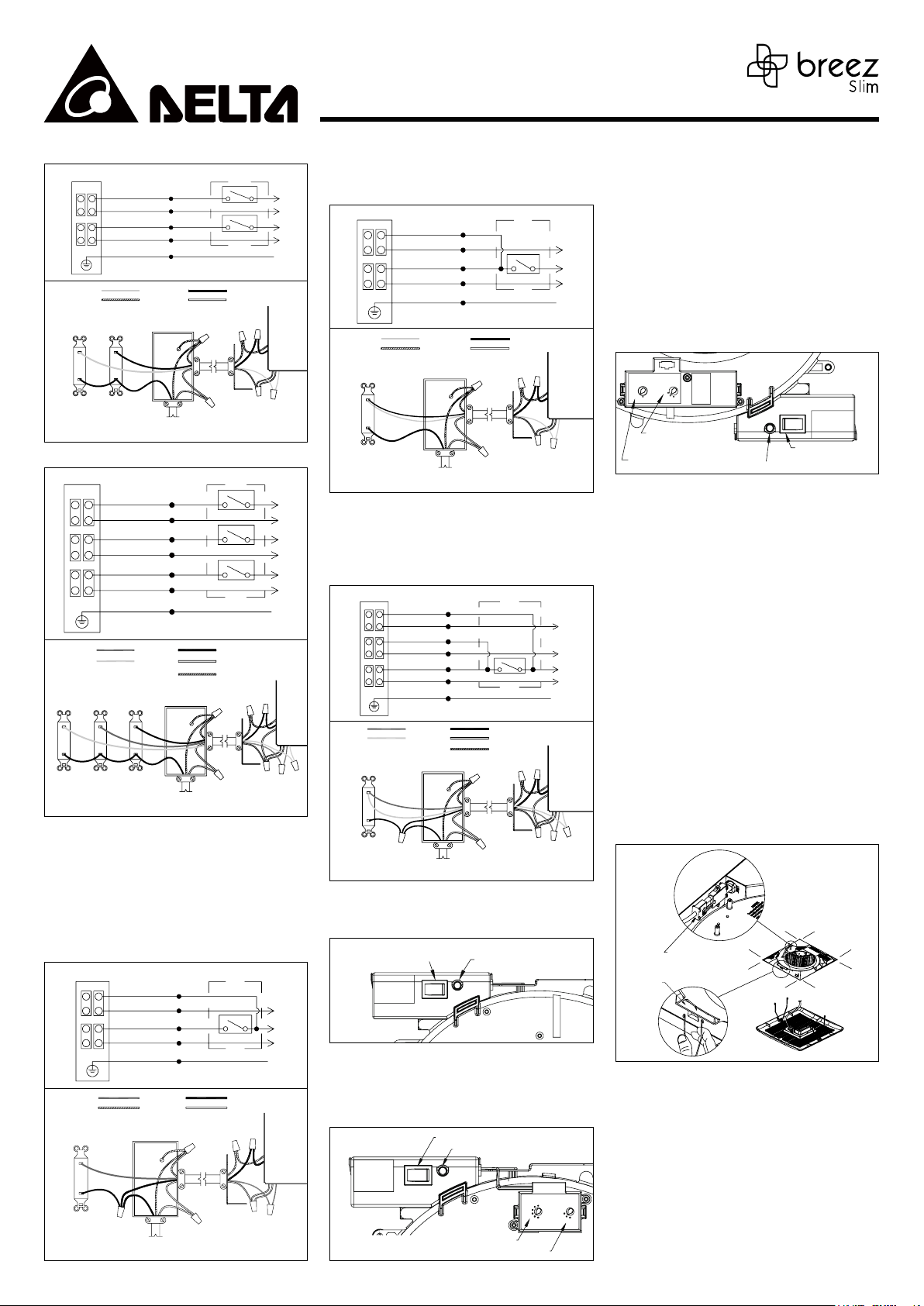
3. SLM50-110LED-C
JUNCTION BOX SWITCH BOX
OFF
ON
POWER SWITCH
OFF
ON
LIGHT SWITCH
BLACKRED
WHITE
WIRING
PLATE
L
N
L
N
GRD
ON/OFF SWITCH
(purchase separately)
POWER
LIGHT
SWITCH
SWITCH
BLACK
WHITE
RED
WHITE
GREEN
GROUND
(bare)
SWITCH BOX
120 VAC
LINE IN
4. SLM80-110DLED-C
JUNCTION BOX SWITCH BOX
OFF
ON
POWER SWITCH
HI
MODE SWITCH
OFF
ON
LIGHT SWITCH
BLACKBLUE
WHITERED
GROUND
(bare)
WIRING
PLATE
L
N
L
N
L
N
GRD
ON/OFF SWITCH
(purchase separately)
LIGHT
SWITCH
SWITCH
MODE
POWER
SWITCH
BLACK
WHITE
BLUE
WHITE
RED
WHITE
GREEN
SWITCH BOX
120 VAC
LINE IN
OTHER WIRING OPTION
See OPERATION section for detail description of mode”.
5. SLM80-110D-C,SLM80-110H-C
Hardwire power.
• Switch OFF: Fan runs 24 hours at “Low speed control
mode”. (SLM80-110D-C only)
• Switch OFF : Fan runs 24 hours at “Humidity control
mode”. (SLM80-110H-C only)
• Switch ON : Fan runs at user adjustable full speed
airflow.
BLACK
WHITE
BLUE
WHITE
GREEN
SWITCH BOX
OFF
ON
SWITCH
BLACKRED
WHITEGROUND
WIRING
PLATE
N
L
N
GRD
JUNCTION BOX
ON/OFF SWITCH
(purchase separately)
(bare)
SWITCH BOX
120 VAC
LINE IN
MODELS: SLM50-110-C, SLM80-110D-C, SLM50-110LED-C, SLM80-110DLED-C, SLM80-110H-C
Page 3.
6. SLM50-110LED-C
Combine power & light to one switch.
• Switch ON : Fan runs at user adjustable full speed
airflow and the light on at the same time.
JUNCTION BOX
ON/OFF SWITCH
(purchase separately)
POWER
SWITCH
(bare)
SWITCH BOX
120 VAC
LINE IN
BLACK
WHITE
RED
WHITE
GREEN
SWITCH BOX
OFF
ON
SWITCH
BLACKRED
WHITEGROUND
WIRING
PLATE
N
L
N
GRD
7. SLM80-110DLED-C
Hardwire power and combine mode & light to one switch.
• Switch OFF: Fan runs 24 hours at “Low speed control
mode”.
• Switch ON: Fan runs “Full speed control mode” and
light on at the same time.
JUNCTION BOX SWITCH BOX
ON/OFF SWITCH
(purchase separately)
BLACK
WHITE
BLUE
WHITE
RED
WHITE
GREEN
RED
SWITCH BOX
120 VAC
LINE IN
ON
SWITCH
BLACKBLUE
WHITE
GROUND
(bare)
WIRING
PLATE
N
OFF
N
L
N
GRD
2. Low speed control mode: Turn the POWER switch on
(MODE switch is off) to operate at the user-adjustable
low speed airflow - the LED will be green
3. Full speed control mode: Turn the POWER switch
& MODE switch on to operate at user-adjustable
full speed mode - the LED indicator will be amber.
When the user turns the MODE switch off, the fan
will continue to run at the full speed until the useradjustable time delay has elapsed, and then will
automatically change to the user-adjustable low
speed airflow. The LED indicator will be green.
Factory setting: High speed airflow 110CFM, low speed
airflow 50CFM, time delay 5 minutes.
Humidity Model:
SLM80-110H-C
LOW SPEED
%RH
CFM
0
8
0
0
8
7
0
0
50
0
6
5
110
50
80
Low speed air volume
preset control
Humidity preset control
• Humidity control mode: Turn the POWER switch on to
LED indicator
HVI LABEL
Full speed air
volume preset control
operate at humidity control mode - the LED indicator
will be blue. When the ambient humidity is higher
than the user-adjustable set-point, the fan will run at
full speed, and the LED indicator is blue. When the
ambient humidity is lower than the set-point, the fan
will continue to run at the full speed until a 10-minute
time delay has elapsed, and then will automatically
change to the user-adjustable low speed airflow.
• Full speed mode: Turn the MODE switch on to
operate at user-adjustable full speed airflow - the LED
indicator will be amber.
• Humidity tolerance is about ±10%. The humidity
switch may need to be adjusted regionally. Longtime
operation will influence the detecting precision as
dust accumulates.
Factory setting: High speed airflow 110CFM, low speed
airflow 50CFM, humidity 60%RH.
GRILLE INSTALLATION
1. LED Models :
SLM50-110LED-C ,SLM80-110DLED-C
Insert the LED lighting connector into the power
socket of main body.
2. All Models :
Insert the mounting springs into the slots and mount
the grille to the fan body.
OPERATION
Single Speed Models:
SLM50-110-C, SLM50-110LED-C
Full speed air volume
preset control, 50,80 or 110 CFM
HVI LABEL
LED indicator
50
80
110
1. Turn the POWER switch on to operate at user
adjustable full speed airflow - the LED indicator will
be green.
Dual Speed Models:
SLM80-110D-C, SLM80-110DLED-C
Full speed air volume preset control
LED indicator
80
HVI LABEL
110
TIME (min)
60
45
0
3
5
1
5
Delay time control
Low speed air volume preset control
0.5
LOW SPEED
CFM
0
8
CARE AND MAINTENANCE
TURN OFF POWER SOURCE. REVIEW ALL SAFETY
PRECAUTION.
See safety information before proceeding. Routine
maintenance should be done at least once a year.
• Never use solvents, thinner or harsh chemicals when
• Do not allow water to enter the motor.
• Do not immerse metal parts in water.
50
• Do not immerse resin parts in water over 140º F.
1. To remove grille, squeeze springs and pull down.
Lighting Connector
Slots
cleaning the fan.
Wash and clean grille with non-abrasive kitchen
detergent. Then wipe dry with a new cloth.
Page 4
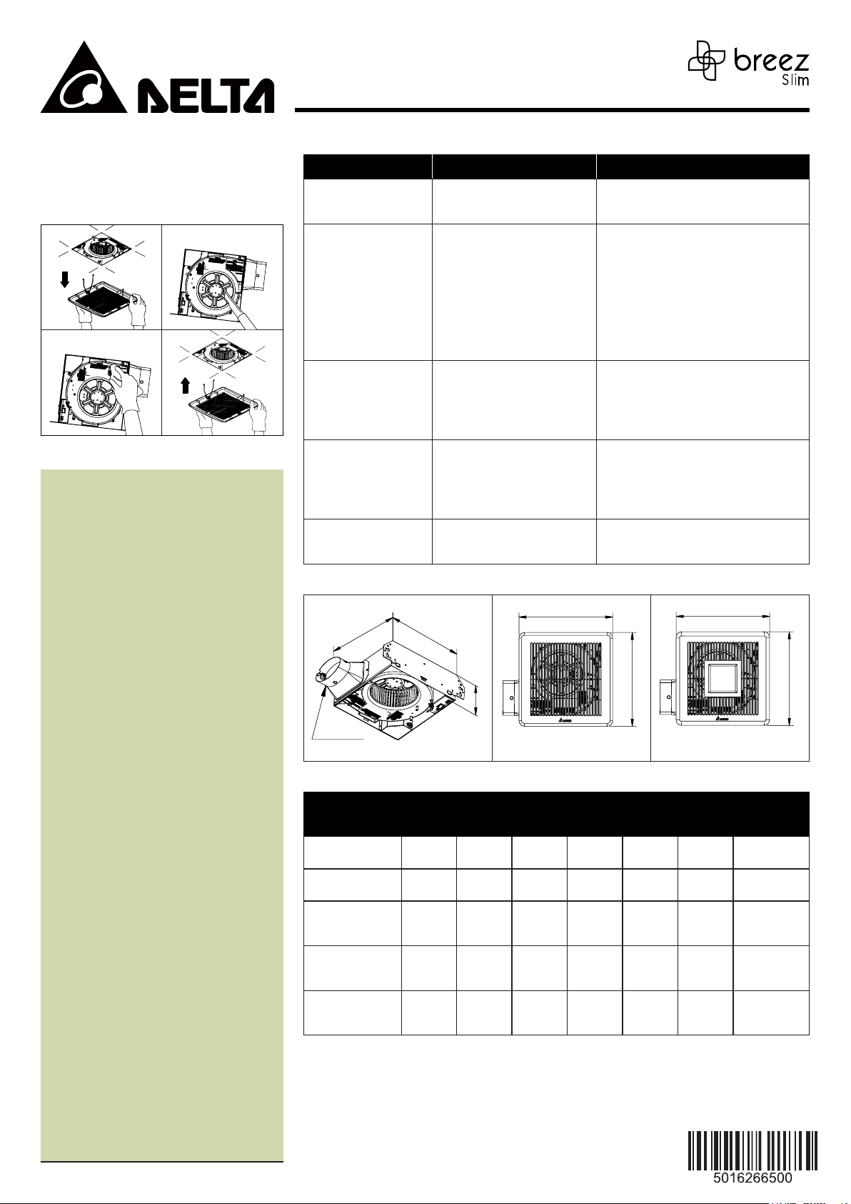
2. Remove dust and dirt from the fan body with a
vacuum cleaner.
3. Using a cloth dampened with non-abrasive kitchen
detergent, remove dust and dirt from the fan body.
Then wipe dry with new cloth.
4. Replace the grille back onto the fan body. Turn on fan
switch to operate fan again.
1
.
3
.
2
.
Vaccum
Cleaner
4
.
WARRANTY
ELTA ELECTRONICS THREE YEAR LIMITED WARRANTY
Delta Electronics Inc. (“Delta Electronics”) warrants
to the original consumer purchaser in the USA and
Canada that the Breez ventilation fan products will
be free from defects in material or workmanship.
This warranty is limited to three (3) years from the
original date of purchase.
Limitations and Exclusions
1. During the warranty period, a replacement
for any defective product will be supplied free
of charge for installation by the consumer.
The warranty provided herein does not cover
charges for labor or other costs incurred in the
troubleshooting, repair, removal, and installation
service.
2. All returns of defective parts or products must
include the product model number, and must be
made through an authorized Delta Electronics
distributor. Authorized returns must be shipped
prepaid. Repaired or replacement products will
be shipped by Delta Electronics F.O.B. shipping
point.
3. Delta Electronics shall not be liable for any
indirect, incidental, consequential, punitive, or
special damages arising out of or in connection
with products use or performance, regardless
of the form of action whether in contract, tort
(including negligence), strict product liability or
otherwise.
4. The warranty does not cover if user does not
comply with manufacturer’s installation manual.
5. To qualify for warranty service, you must notify
Delta Electronics at the address or telephone
number below.
6. Delta Electronics shall have no liability to the
original owner-user with respect to any defect
caused by abuse, misuse, neglect, improper
transportation or storage, improper testing,
improper installation, improper operation,
improper use, improper maintenance,
improper repair, improper alteration, improper
modification, tampering or accident of products
or parts thereof, or unusual deterioration or
degradation of products or parts thereof due to a
physical environment beyond the requirements
of products’ specifications.
MODELS: SLM50-110-C, SLM80-110D-C, SLM50-110LED-C, SLM80-110DLED-C, SLM80-110H-C
Page 4.
TROUBLE SHOOTING
PROBLEM POSSIBLE CAUSE CORRECTIVE ACTION
The fan is not turning on 1. Power off
The fan seems louder than
it
should
The fan is not clearing the
room
The fan keeps running even
though the house humidity
level is lower than useradjustable set-point.
The light is not turning ON 1. Power off
2. Faulty switch
3. Faulty wire connection
1. CFM too great
2. Damper not working properly
or damaged
3. Bend in duct too close to fan
discharge
4. Fan discharge reduced to fit
smaller duct
5. Fan body not securely attached
1. Insufficient intake airflow within
room
2. Insufficient CFM
1. Our sensor tolerance is +/- 10%
RH
2. Outdoor humidity is back drafting
to the fan
2. Faulty switch
3. Faulty wire connection
DIMENSIONS
111/4" 101/2"
4"
4"Oval Duct
SLM50-110-C, SLM80-110D-C,
SLM80-110H-C
SPECIFICATIONS
Model No.
SLM50-110-C 120 60 110 16.5 8.2
SLM80-110D-C 120 60 110 16.5 8.2
SLM50-110LED-C 120 60 110 16.5 8.6
SLM80-110DLED-C 120 60 110 16.5 8.6
SLM80-110H-C 120 60 110 16.5 8.2
Note: Specifications subject to change without notice.
Voltage
(V)
Frequency
(Hz)
Air Flow
@ 0.1SP
(CFM)
1. Make sure power supply is on.
2. Test or replace switch.
3. Check wire in switch box
1. Be sure the CFM rating on the fan matches
the size of your room.
2. Check damper to ensure it is opening and
closing properly. If the damper has become
damaged, please call Customer Service.
3. Be sure you do not have any sharp bends in
duct closer than 18 in. to the fan discharge.
4. Use recommended size ducting to reduce
fan noise.
5. Be sure the fan is securely attached to your
ceiling joists.
1. Be sure a door or window is slightly ajar or
opened to allow airflow. The fan is not able
to draw air out of the room without enough
airflow to draw in from.
2. Be sure the CFM rating on the fan matches
the requirements for your room size.
1. Continue to let the fan run since it is good to
keep venting the house and the electric bill
is minimal (approximately less than $10 per
year).
2. Turn the fan off when not in use.
1. Make sure power supply is on.
2. Test or replace switch.
3. Check wire in switch box.
13"
13"
SLM50-110LED-C, SLM80-110DLED-C
Power
@ 0.1SP
(W)
Weight Note Light Spec
Single
Speed
Dual
Speed
Single
speed
Dual
Speed
Humidity
sensing
13"
13"
-
-
13Watts,
850Lumens,
3000K, CRI90
13Watts,
850Lumens,
3000K, CRI90
-
Address:
46101 Fremont Boulevard, Fremont, CA 94538
US Toll Free Number:
1-888-979-9889 - Technical Support
1-877-685-4384 - Customer Sales Support
www.deltabreez.com
 Loading...