

Delta VX 600VA, VX 1000VA, VX 1500VA Installation & Operation Manual
Delta UPS – Agilon Family
1
2
3
VX Series, Line-interactive
600-1500 VA
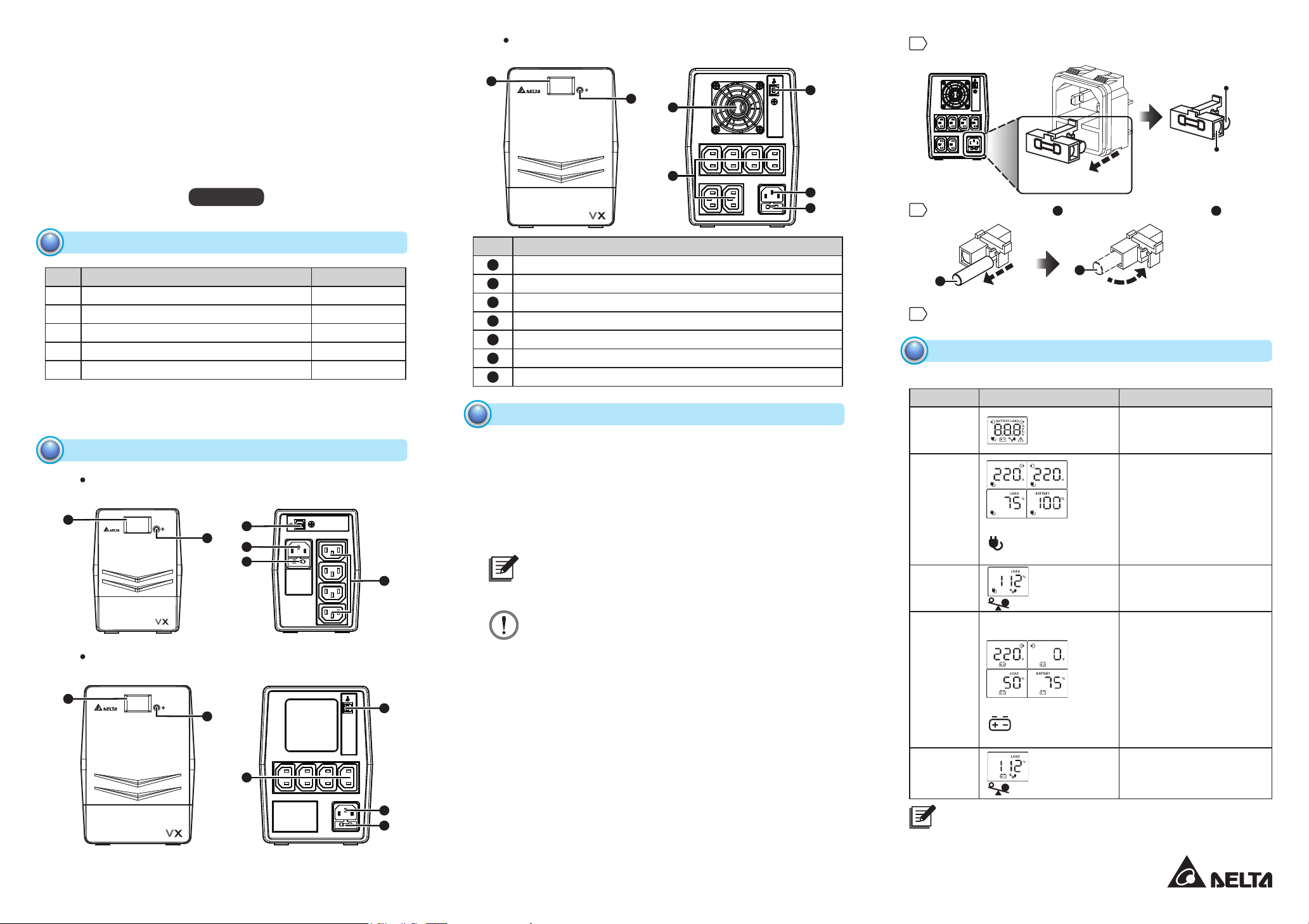
1
1500VA
(Front Panel) (Rear Panel)
2
7
Remove the fuse cover from the rear panel.
(Rear Panel)
6
Original Fuse
(Provided)
Installation & Operation Quick Guide
ENGLISH
Package Inspection
1
No. Item Q'ty
1 UPS 1 PC
2 Quick Guide 1 PC
3 Output Power Cord (10A) 1 PC
4 USB Cable 1 PC
5 AC Power Cord 1 PC
Remove the UPS from its package and inspect it for damage that may
have occurred during shipping. If any damage is discovered, re-pack
the unit and return it to the place of purchase.
Front Panel & Rear Panel
2
600VA
www.deltapowersolutions.com
(Front Panel) (Rear Panel)
1
2
1000VA
(Front Panel) (Rear Panel)
1
2
6
4
5
3
3
6
4
5
No. Item
1
LCD Touch Panel
2
ON/ OFF Button
3
Output Socket
4
AC Input
5
Fuse
6
USB Port
7
Cooling Fan (Only For 1500VA Model)
Operation
3
Connect to Utility Power
yy
Connect the AC power cord to the utility power. Then, the UPS will
start to charge its inside battery (batteries). For best result, charge the
battery (batteries) for 6 hours prior to initial use. It is not recommended
to connect the UPS’s AC power cord to any generator.
Plug in Equipment
yy
Plug your equipment to the Output Socket on the rear panel of the
UPS.
3
NOTE:
Make sure that the UPS is powered on to protect all important
devices from data loss during power failure.
WARNING:
NEVER connect a laser printer or scanner to the Output
Socket of the UPS. The equipment may draw significant
power to overload the UPS.
Connect to USB Port and Install Software
yy
Connect one end of the supplied USB cable to your PC and the other
to the USB port located at the rear of the UPS. Download the latest
version of ViewPower software (http://www.deltapowersolutions.com/
en/mcis/600va-1500va-single-phase-ups-vx-series-software-download.
php) to your hard drive. Follow on-screen instructions to complete the
software installation.
Turn On/ Off the UPS
yy
When the UPS is OFF, press the ON/ OFF Button to turn on the UPS
and the LCD will be on. When the UPS is ON, press the ON/ OFF
Button to turn off the UPS and the LCD will shut off.
Fuse Replacement
yy
When the UPS always runs in battery mode, it might be because the
fuse is damaged. If yes, please follow the following procedures to
replace the fuse.
(Pull)
4
5
Replace the original fuse with the provided backup fuse .
1
(Take Out) (Install)
Replace the fuse cover back to the rear panel.
LCD Display
4
Operation Display:
yy
UPS Mode LCD Touch Panel Description
UPS
Power On
AC Mode
When AVR is functioning,
second.
Overload
In AC
Mode
Battery
Mode
When battery level is low,
Overload
In Battery
Mode
NOTE:
If backlight shuts off, you can activate it by touching the screen.
Continue to the Next Page
(Fuse Cover)
1
2
icon will ash every
icon will ash.
icon will ash.
icon will ash.
When the UPS is powered
on, it will enter this mode
for 4 seconds.
LCD information will be
displayed in the following
order when the LCD
is touched.
1. Output voltage
2. Input voltage
3. Load level
4. Battery capacity
When overload occurs,
alarm will beep every 0.5
second.
Alarm will beep every
10 seconds and LCD
information will be
displayed in the following
order when the LCD
is touched.
1. Output voltage
2. Input voltage
3. Load level
4. Battery capacity
When overload occurs,
alarm will beep every 0.5
second.
Backup Fuse
(Provided)
2
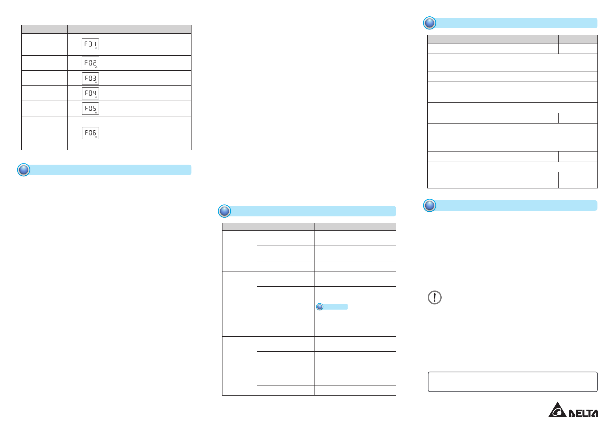
Fault Code Table:
yy
Fault Condition LCD Touch Panel Solutions
Output Short
Circuited
Overload Fault
Over Charge
Fault
Battery Too Low
Fault
Battery Mode
Output High Fault
Over
Temperature
If any fault alarm occurs, please call for service immediately.
Safety Caution
5
SAVE THESE INSTRUCTIONS-This quick guide contains important
instructions that should be followed during installation and
maintenance of the UPS and battery (batteries).
The UPS utilizes voltage that may be hazardous. Do not attempt
yy
to disassemble the unit. The unit contains no user replaceable
parts. Only factory service personnel may perform repairs.
This pluggable type A equipment with battery (batteries) already
yy
installed by the supplier is operator installable and may be operated by laymen.
The mains socket outlet that supplies the UPS shall be installed near
yy
the UPS and shall be easily accessible.
During the installation of this equipment it should be assured that
yy
the sum of the leakage current of the UPS and the connected loads
does not exceed 3.5mA.
Connection to any other type of receptacle other than a two-pole,
yy
three-wire grounded receptacle may result in shock hazard as well
as violate local electrical codes.
In the event of an emergency, press the ON/ OFF Button and dis-
yy
connect the power cord from the AC power supply to properly disable the UPS.
Do not allow any liquid or any foreign object to enter the UPS. Do
yy
not place beverages or any other liquid-containing vessels on or
near the unit.
The unit is intended for installation in a controlled environment (tem-
yy
perature controlled, indoor area free of conductive contaminants).
Avoid installing the UPS in any location where there is standing or
running water, or excessive humidity.
Do not plug the UPS input into its own output.
yy
Do not attach a power strip or surge suppressor to the UPS.
yy
Do not attach non-computer-related items, such as medical equip-
yy
ment, life-support equipment, microwave ovens, or vacuum cleaners
to the UPS.
Do not dispose of battery (batteries) in a re as they may explode.
yy
www.deltapowersolutions.com
Disconnect short-circuited
loads and restart the UPS
again.
Disconnect all output loads
and restart the UPS again.
Call for service immediately.
Please replace the battery
(batteries).
Call for service immediately.
1. Turn off the UPS and wait
for cooling.
2. Or remove excessive
loads and wait for cooling.
A battery can present a risk of electrical shock and high short circuit
yy
current. The following precautions should be observed when working
on batteries:
1. Remove watches, rings, or other metal objects from the hands.
2. Use tools with insulated handles.
3. Wear rubber gloves and boots.
4. Do not lay tools or metal parts on top of battery (batteries).
5. Disconnect charging source prior to connecting or disconnecting
the terminals of battery (batteries).
Internal battery voltage is 12Vdc. Battery type is sealed, lead-acid,
yy
6-cell battery.
Servicing of batteries should be performed or supervised by personnel
yy
knowledgeable of batteries and the required precautions. Keep unauthorized personnel away from batteries.
When replacing battery (batteries), replace with the same number and
yy
type of sealed lead-acid battery (batteries).
Do not open or mutilate the battery or batteries. Release electrolyte is
yy
harmful to the skin and eyes. It may be toxic.
Attention! Hazardous through electric shock. Even disconnection of
yy
this unit from the mains, hazardous voltage still may be accessible
through supply from the battery (batteries). The battery supply should
be therefore disconnected in the plus and minus pole at the connectors of the battery (batteries) when maintenance or service work inside
the UPS is necessary.
To reduce the risk of overheating the UPS, do not cover the UPS’s
yy
cooling vents and avoid exposing the unit to direct sunlight or installing the unit near heat emitting appliances such as heaters or furnaces.
Unplug the UPS prior to cleaning and do not use liquid or spray deter-
yy
gent.
Troubleshooting
6
Problem
Nothing is
displayed
on the LCD
panel
The UPS
always runs
in battery
mode.
The UPS
continuously
beeps.
Backup time
is too short.
If any abnormal situations occur that are not listed above, please call for
service immediately.
Possible Cause Solutions
The UPS is not on.
Battery voltage is too
low.
Battery fault. Replace the battery (batteries).
The power cord
becomes loose.
The fuse is damaged.
Please check the
Fault Code Table for
the details.
Battery voltage is too
low.
Overload.
Battery defect. Replace the battery (batteries).
Press the ON/ OFF Button again
to turn on the UPS.
Charge the battery (batteries) at
least 6 hours.
Re-plug the power cord.
Replace the fuse. For how to
replace the fuse, please refer to
Operation
3
Please check the Fault Code
Table for the details.
Charge the battery (batteries) at
least 6 hours.
Remove some unnecessary
loads. Before reconnecting
equipment, please verify that the
load matches the UPS capability
specied in the specs.
.
Technical Specifications
7
Model 600VA 1000VA 1500VA
Capacity 600VA/360W 1kVA/600W 1.5kVA/900W
Nominal
Input Voltage
Input Voltage Range 170 ~ 280 Vac
Output Voltage 230 Vac ± 10% (Bat. mode)
Transfer Time Typical 2 ~ 6 ms
Waveform Simulated Sine Wave
Battery Type & No. 12V/7Ah x 1 12V/7Ah x 2 12V/9Ah x 2
Charging Time Typical 6 ~ 8 hours
Dimensions
(D x W x H)
Net Weight (kgs) 4.4 8.2 10.4
Humidity 0 - 90% RH @ 0 - 40°C (non-condensing)
Noise Level Less than 40dB
* Specications are subject to change without notice.
Warranty
8
Seller warrants this product, if used in accordance with all applicable
instructions, to be free from original defects in material and workmanship within the warranty period. If the product has any failure problem
within the warranty period, Seller will repair or replace the product at its
sole discretion according to the failure situation.
This warranty does not apply to normal wear or to damage resulting
from improper installation, operation, usage, maintenance or irresistible force (i.e. war, fire, natural disaster, etc.), and this warranty
also expressly excludes all incidental and consequential damages.
Maintenance service for a fee is provided for any damage out of the
warranty period. If any maintenance is required, please directly contact
the supplier or Seller.
WARNING:
The individual user should take care to determine prior to
use whether the environment and the load characteristic are
suitable, adequate or safe for the installation and the usage of
this product. The Quick Guide must be carefully followed. Seller
makes no representation or warranty as to the suitability or
tness of this product for any specic application.
Copyright © 2017 by Delta Electronics Inc. All Rights Reserved. This
Quick Guide is subject to change without prior notice.
Version Date : 2017_03_28
300 x 101 x
142 mm
230 Vac
320 x 130 x 182 mm
Less than
45dB
 Loading...